

Page 1
INSTRUCTIONS
309317
This manual contains important
warnings and information.
READ AND KEEP FOR REFERENCE.
INSTRUCTIONS
US Patent Pending
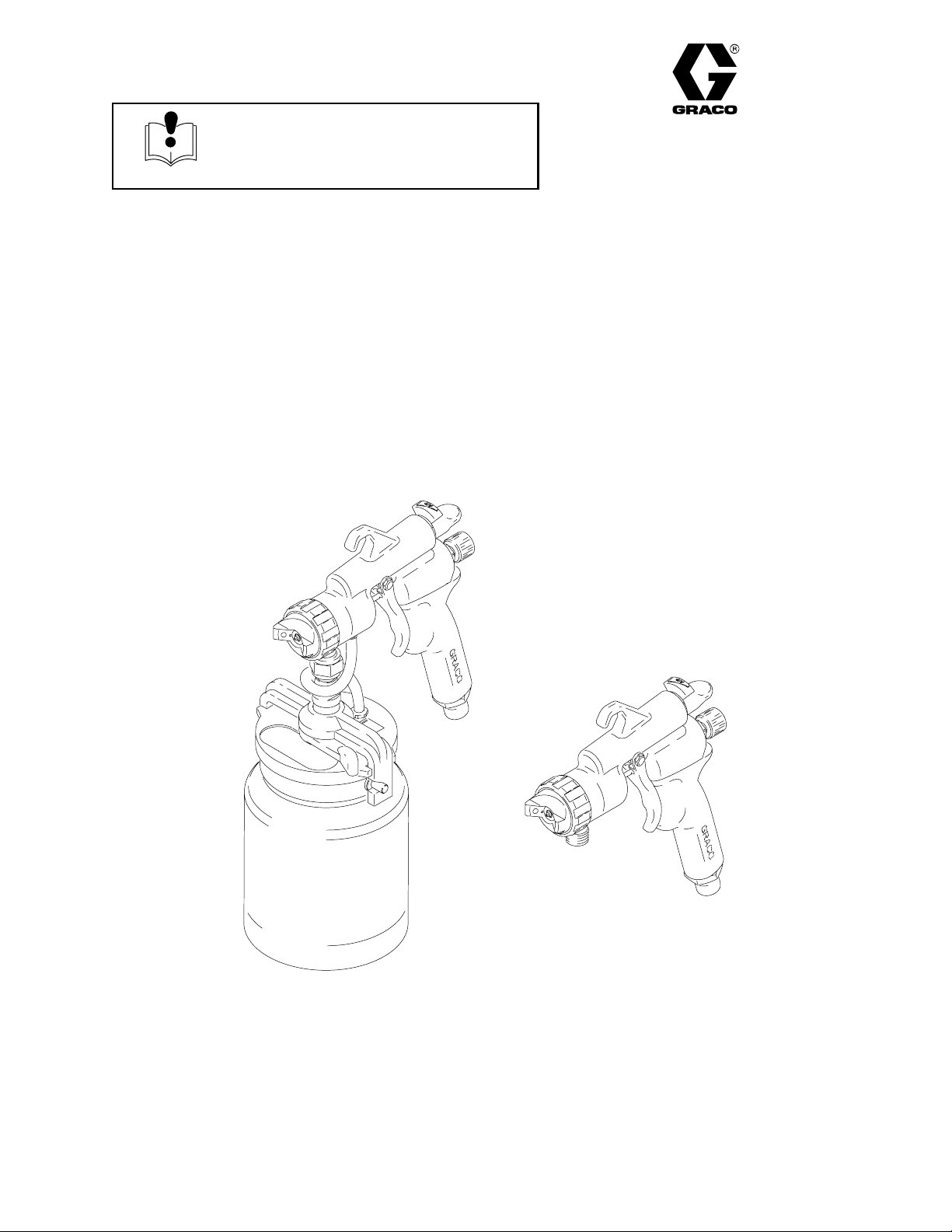
HVLP–Turbine Guns
10 psi (0.07 MPa, .7 bar) Maximum Inlet Air Pressure
50 psi (0.35 MPa, 3.5 bar) Maximum Inlet Fluid Pressure
Related Manuals
309205 – HVLP–Turbine Gun for maintenance and service instructions
309243 – HVLP Turbine
309244 – HVLP Compressor/Cart
Rev. B
Cup Feed
Includes 1-quart (1 liter) cup
Model 244113, without fluid set
Model 244117, with # 3 fluid set
GRACO INC. P.O. BOX 1441 MINNEAPOLIS, MN 55440–1441
ECOPYRIGHT 2001, GRACO INC.
Graco Inc. is registered to I.S. EN ISO 9001
Remote Pressure Feed
Model 244115, without fluid set
Model 244118, with # 3 fluid set
T10746
Page 2

Table of Contents
Symbols 2. . . . . . . . . . . . . . . . . . . . . . . . . . . . . . . . . . . . . .
Warnings 3. . . . . . . . . . . . . . . . . . . . . . . . . . . . . . . . . . . . . .
Component Identification 4. . . . . . . . . . . . . . . . . . . . . . . .
Setup 7. . . . . . . . . . . . . . . . . . . . . . . . . . . . . . . . . . . . . . . . .
Spray 7. . . . . . . . . . . . . . . . . . . . . . . . . . . . . . . . . . . . . . . . .
Shutdown 8. . . . . . . . . . . . . . . . . . . . . . . . . . . . . . . . . . . . .
Parts List 15. . . . . . . . . . . . . . . . . . . . . . . . . . . . . . . . . . . . .
Parts Drawing 14. . . . . . . . . . . . . . . . . . . . . . . . . . . . . . . . .
Technical Data 16. . . . . . . . . . . . . . . . . . . . . . . . . . . . . . . .
Graco Phone Number NO TAG. . . . . . . . . . . . . . . . . . . .
Warning Symbol
WARNING
This symbol alerts you to the possibility of serious
injury or death if you do not follow instructions.
Caution Symbol
CAUTION
This symbol alerts you to the possibility of damage to
or destruction of equipment if you do not follow instructions.
You will need:
Cleaning fluids: a compatible solvent; water–based paint also requires soap and water.
Suggested proper clothing:
• Safety glasses • Sturdy boots or shoes
• Respirator • Gloves
2 309317
Page 3
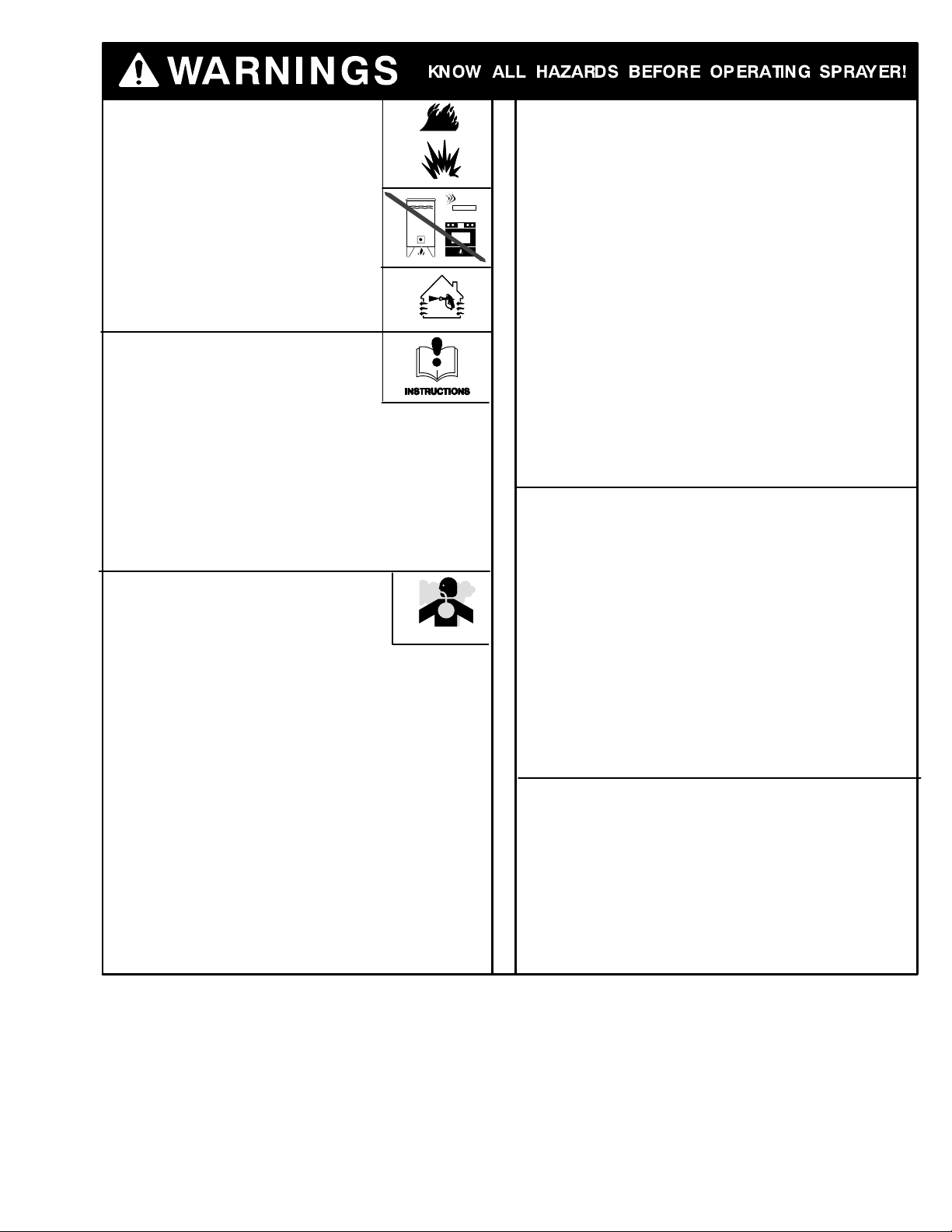
Fire and explosion hazard: Solvent and paint
fumes can ignite or explode.
D Sprayers generate sparks. Keep sprayer at least
20 feet (6 m) from explosive vapors.
DUse in an extremely well ventilated area.
DEliminate all ignition sources; such as pilot lights,
cigarettes and static arcs from plastic drop cloths.
Do not plug or unplug power cords or turn lights
on or off in spray area.
DGround Sprayer, object being sprayed, paint and
solvent pails.
DDo not use 1,1,1-trichloroethane, methylene chlo-
ride, other halogenated hydrocarbon solvents or
fluids containing such solvents in pressurized aluminum equipment. Such use could result in a
chemical reaction, with the possibility of explosion.
Equipment Misuse Hazard: Equipment misuse
can cause the equipment to rupture or malfunction
and result in serious injury.
DBefore operating equipment, read all instruction
manuals, tags, and labels.
DCheck equipment daily. Repair or replace worn
or damaged parts immediately.
DDo not exceed maximum working pressure (MWPR) of the lowest–rated
system component
DUse fluids and solvents that are compatible with the equipment
wetted parts. See Specifications on page for this information.
DWear hearing protection when operating this equipment.
DDo not “blow back” fluid; this is not an air spray system
DFollow Pressure Relief before cleaning, checking or servicing the
equipment.
TOXIC FLUID HAZARD: Hazardous fluid or toxic
fumes can cause serious injury or death if
splashed in eyes or on skin, inhaled, or swallowed.
DKnow specific hazards of fluid you are
using and take protective measures as
recommended by the fluid and solvent manufacturer.
3309317
Page 4
D
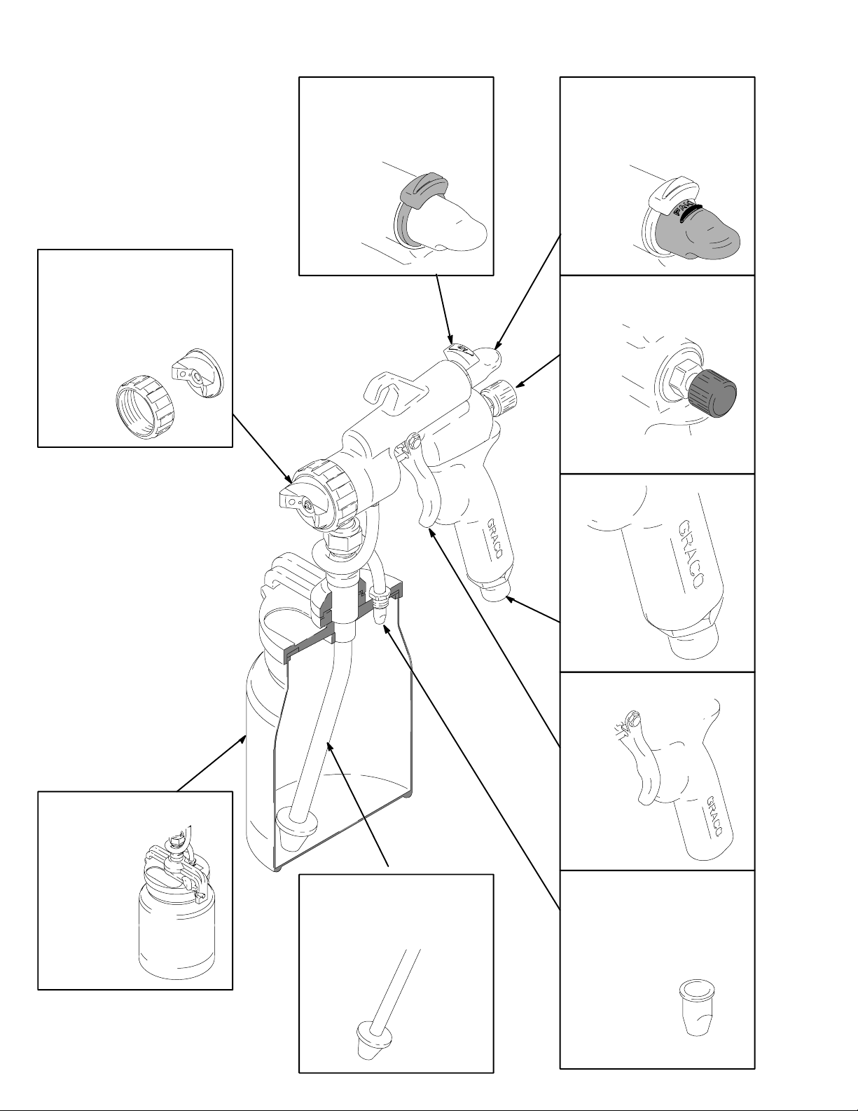
Component Identification
Air cap/retaining ring – Adjusts
fan direction
Air flow control – Adjusts TOTAL
air flow to spray gun
Pattern Adjustment Knob –
Adjusts pattern from fan to
round
Fluid flow/Pattern size control –
Adjusts fluid volume
Air inlet
Cup
4 309317
Swivel tube and strainer
EasyGlidet Trigger
Duckbill check valve
Page 5
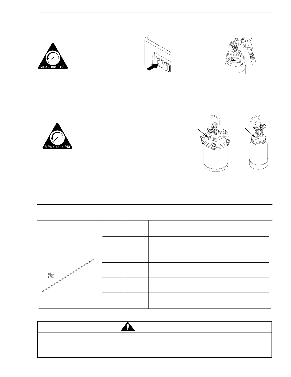
PRESSURE RELIEF – Follow this procedure when cleaning, repairing or shuting down
2
sprayer
For Cup Guns
Follow these
instructions whenever
you stop spraying.
1. Turn off turbine. 2. Unlatch cup
For Pressure Feed Guns
Follow these
instructions whenever
you stop spraying.
TIP SELECTION
A Tip consists of a fluid
nozzle, and fluid needle.
Use the following chart
for recommendations.
1. Turn off air supply to the pot.
2. Open pressure relief (A) on
pot until pressure is completely
relieved. Close relief.
Fluid Set
#2
244123
#3
244124
#4
244125
Tip Size
0.8 mm
(0.032 in)
1.3 mm
(0.051 in)
1.8 mm
(0.071 in)
Ink, dye and non–wiping stain.
Water base lacquer, urethane, varnish, stain, and automotive finish.
Lacquer, urethane, varnish, stain, primer, enamel and epoxy.
Fluid Usage
A
8069A
A
2 quart
0288
#5
244126
#6
244127
2.2 mm
(0.087 in)
2.5 mm
(0.098 in)
Lacquer, urethane, varnish, stain, primer, enamel, epoxy and
higher output industrial finishes.
Latex, multi–spec, oil wall paint, industrial finishes, butyrate, and nitrate dope.
Installing the Fluid Set
CAUTION
Trigger the gun whenever you tighten or remove the nozzle. This keeps the needle seat away from
the nozzle seating surface and prevents the seat from being scratched.
5309317
Page 6
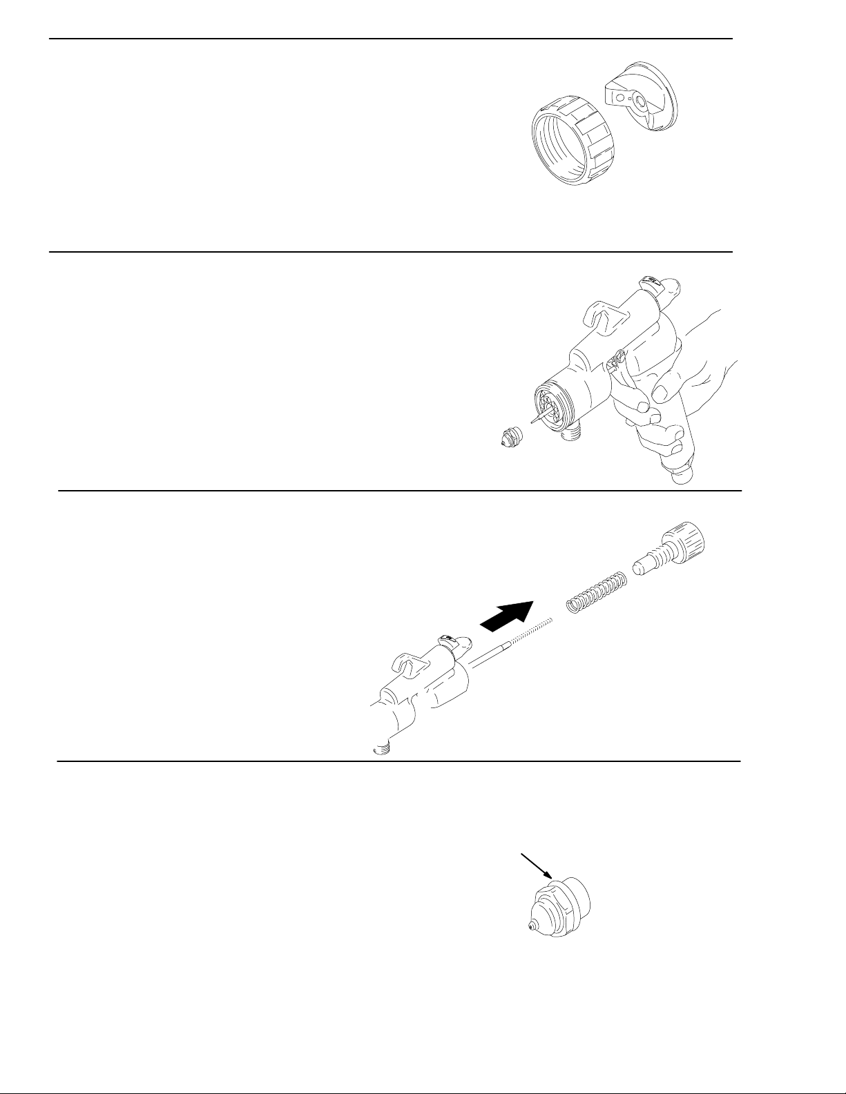
1. Use your hand to loosen and remove the air cap retaining ring
and air cap housing.
2. Test spray pattern and atomization while holding gun about 6
to inches (150 to 200 mm) from test piece.
3. While triggering the gun, use your hand to loosen and remove the nozzle.
.
4. Use your hand to loosen and remove the fluid knob assembly and
compression ring from the back of the gun and remove the old needle.
5. Insert the needle assembly in the back of the gun. Reassemble nozzle, air cap housing and air cap re-
taining ring. Hand tighten.
A
Note: Nozzle should always have an o–ring (A).
6 309317
Page 7

Setup
6. Connect air hose to gun and turbine.
7. For cup gun, turn fluid control out until trigger movement is not restricted.
Caution: Turning knob too far will remove it.
For remote pressure pot, hold gun parallel to floor and adjust fluid pressure
to an 8 to 10 inch (203 to 254 mm) fluid stream.
NOTE: Heavier fluids or longer fluid hoses require greater pressures.
8. Reduce and test catalyze all paint to manufacturer’s specifications.
S If no reduction instructions are given, mix the fluid thoroughly, then gradually mix in reducer. To check
the consistency of the fluid. Remove the stir stick from the thinned paint. When the paint streaming off
the stick breaks into droplets, the first few drops should be one second apart.
S To compensate for faster drying time of turbine systems, use a reducer one step slower than used for
conventional air spray systems.
9. Remove cup. Fill 3/4 full. DO NOT OVERFILL. Reattach and latch cup.
7309317
Page 8

SPRAY
10. Plug turbine power cord into a grounded outlet.
11. Open air control valve.
12. Turn turbine on. Wait several minutes prior
to spraying to allow warm–up time.
13. Turn air cap to obtain desired direction.
8 309317
Page 9

14. Lock air cap with retaining ring.
15. Select spray pattern by adjusting the fluid knob
and pattern selection knob. The air control adjusts the TOTAL air to the pattern and gun.
Round Pattern
Set knob to RND
Vertical Pattern
Set knob to FAN
Nozzle
Air cap
Retaining ring
air control
pattern selection
knob
Horizontal Pattern
Set knob to FAN
fluid knob
Note: If fluid is not atomizing properly, fluid may need to be thinned further, or a different tip size may be used.
16. Hold gun perpendicular, 6–8 inches from surface. Move
gun first, then pull gun trigger to spray.
9309317
Page 10

17. To control over–spray, reduce air flow or reduce fluid volume.
Note: If fluid is not atomizing properly, fluid may need to be thinned further, or a different
tip size may be used.
Swivel Tube Adjustment
The adjustable swivel tube allows the HVLP–Turbine Gun to be held in any position why spraying. To adjust the
position of the tube in the cup:
1. Loosen the nut (A) with a wrench (42).
2. Rotate the cup to the desired spray position.
3. Retighten the nut (A) with a wrench (42).
A
A
cup
10 309317
swivel tube
Swivel tube positioned
for spraying DOWN
swivel tube
Swivel tube positioned
for spraying UP
Page 11

Shutdown
Cleaning the Spray Gun (solvent/oil–based)
1. Close air valve.
2. Perform Pressure Relief Procedure. Remove and empty cup.
3. Add 1.5 inches of compatible cleaning solvent. Reinstall cup.
4. Turn fan control to round spray pattern.
11309317
Page 12

5. Turn air control valve to approximately half way.
6. Trigger gun until solvent runs clean.
7. Turn turbine off.
8. Disconnect hose from gun. Perform Pressure Re-
lief. Properly dispose of excess solvent.
12 309317
Page 13

Shutdown (water base)
1. Turn turbine off.
2. Perform Pressure Relief Procedure. Remove cup, empty and clean
with soap and water.
3. Remove air cap and nozzle and clean with water and brush.
4. Clean fluid tube and nozzle housing with water and brush.
13309317
Page 14

Parts for HVLP–Turbine Gun
Model Nos. 244113, 244115, 244117, 244118
19a
14b
19
23
21
13
15
14a
12
25
9
18
27
19b
22
26
17
1
14b
8
7
2
4
2a
28
6
5
2b
11
31
10
14 309317
24
30d
30c
32
30a
TI0745
Page 15

Parts for HVLP–Turbine Gun
Model Nos. 244113, 244115, 244117, 244118
Ref.
No.
1 244426 BODY, gun 1
2 244429 HOUSING, nozzle 1
2a 196414 HOUSING
2b 112085 PACKING, o–ring 1
4 113137 PACKING, o–ring 1
5 188494 SPREADER, u-cup, 1
6 188495 PACKING, u–cup 1
7 196438 SPACER, packing 1
8 192352 SCREW, packing 1
9 192348 NUT, hex; 1/2–20 UNF 1
10 196439 TRIGGER 1
11 203953 SCREW, cap, hex head 1
12 192272 PIN, pivot 1
13 196415 RING, retaining, air cap 1
14 244124 FLUID SET 1
14a NOZZLE, fluid 1
14b NEEDLE ASSY 1
15 244226 HOUSING, air cap 1
17 188493 PACKING, u–cup, gun 1
18 196462 HANDLE, gun 1
19 244428 HOUSING, valve, fluid 1
19a 110066 PACKING, o–ring 1
19b 110453 PACKING, u–cup 1
21 196649 KNOB, fluid control 1
22 114069 SPRING, compression 1
23 114072 SPRING, compression 1
24 196464 COUPLER, male 1
Part No. Description Qty.
Ref.
No.
25 243840 VALVE, air fan 1
26 243842 VALVE, air 1
27 196463 TUBE, handle 1
28 196468 FITTING, adapter 1
30† 244130 CUP UNDER, kit 1
30a† M71667 CUP, 1 quart 1
30b† 244133 KIT, air tube, 5-pack (not
30c† 244135 VALVE, duckbill 1
30d† 240265 GASKET, cup 1
31† M70394 STEM, air 1
32 193218 STRAINER 1
33 M70613 BRUSH, cleaning (not
34 070303 LUBRICANT, grease (not
35 197448 TOOL, wrench (not shown) 1
*Not included on model 244113 or 244115.
†Not included on model 244115 or 244118.
Part No. Description Qty.
shown)
shown)
shown)
1
1
1
15309317
Page 16

Technical Data
Maximum inlet fluid pressure 50 psi (0.35 MPa, 3.5 bar). . . . . . . . . . . . . . . . . . . . . . . . . . . . . . . . . . . . . . . . . . . . . . . . . . . .
Maximum inlet air pressure 10 psi (0.07 MPa, .7 bar). . . . . . . . . . . . . . . . . . . . . . . . . . . . . . . . . . . . . . . . . . . . . . . . . . . . . .
Air inlet Quick-disconnect. . . . . . . . . . . . . . . . . . . . . . . . . . . . . . . . . . . . . . . . . . . . . . . . . . . . . . . . . . . . . . . . . . . . . . . . . . . . . .
Fluid inlet 3/8 nps. . . . . . . . . . . . . . . . . . . . . . . . . . . . . . . . . . . . . . . . . . . . . . . . . . . . . . . . . . . . . . . . . . . . . . . . . . . . . . . . . . . . . .
Sound levels per ISO 3744
Sound power level less than 65.0 dB(A). . . . . . . . . . . . . . . . . . . . . . . . . . . . . . . . . . . . . . . . . . . . . . . . . . . . . . . . . . . . . . . .
Sound pressure level less than 65.0 dB(A). . . . . . . . . . . . . . . . . . . . . . . . . . . . . . . . . . . . . . . . . . . . . . . . . . . . . . . . . . . . .
Wetted parts
Bare spray gun stainless steel, aluminum. . . . . . . . . . . . . . . . . . . . . . . . . . . . . . . . . . . . . . . . . . . . . . . . . . . . . . . . . . . . .
Spray gun cups aluminum, polyethylene. . . . . . . . . . . . . . . . . . . . . . . . . . . . . . . . . . . . . . . . . . . . . . . . . . . . . . . . . . . . . . .
2-quart accessory remote pressure pot aluminum, polyethylene. . . . . . . . . . . . . . . . . . . . . . . . . . . . . . . . . . . . . . . . . . .
21/2-gallon accessory remote pressure pot steel with solvent-resistant finish, EPDM gasket (standard). . . . . . . . . .
16 309317
Page 17

Notes
17309317
Page 18

Graco Standard Warranty
Graco warrants all equipment manufactured by Graco and bearing its name to be free from defects in material and workmanship on the
date of sale to the original purchaser for use. With the exception of any special, extended, or limited warranty published by Graco,
Graco will, for a period of twelve months from the date of sale, repair or replace any part of the equipment determined by Graco to be
defective. This warranty applies only when the equipment is installed, operated and maintained in accordance with Graco’s written
recommendations.
This warranty does not cover, and Graco shall not be liable for general wear and tear, or any malfunction, damage or wear caused by
faulty installation, misapplication, abrasion, corrosion, inadequate or improper maintenance, negligence, accident, tampering, or substitution of non–Graco component parts. Nor shall Graco be liable for malfunction, damage or wear caused by the incompatibility of
Graco equipment with structures, accessories, equipment or materials not supplied by Graco, or the improper design, manufacture,
installation, operation or maintenance of structures, accessories, equipment or materials not supplied by Graco.
This warranty is conditioned upon the prepaid return of the equipment claimed to be defective to an authorized Graco distributor for
verification of the claimed defect. If the claimed defect is verified, Graco will repair or replace free of charge any defective parts. The
equipment will be returned to the original purchaser transportation prepaid. If inspection of the equipment does not disclose any defect
in material or workmanship, repairs will be made at a reasonable charge, which charges may include the costs of parts, labor, and
transportation.
THIS WARRANTY IS EXCLUSIVE, AND IS IN LIEU OF ANY OTHER WARRANTIES, EXPRESS OR IMPLIED, INCLUDING BUT
NOT LIMITED TO WARRANTY OF MERCHANTABILITY OR WARRANTY OF FITNESS FOR A PARTICULAR PURPOSE.
Graco’s sole obligation and buyer’s sole remedy for any breach of warranty shall be as set forth above. The buyer agrees that no other
remedy (including, but not limited to, incidental or consequential damages for lost profits, lost sales, injury to person or property, or any
other incidental or consequential loss) shall be available. Any action for breach of warranty must be brought within two (2) years of the
date of sale.
Graco makes no warranty, and disclaims all implied warranties of merchantability and fitness for a particular purpose in connection
with accessories, equipment, materials or components sold but not manufactured by Graco. These items sold, but not manufactured
by Graco (such as electric motors, switches, hose, etc.), are subject to the warranty, if any, of their manufacturer. Graco will provide
purchaser with reasonable assistance in making any claim for breach of these warranties.
In no event will Graco be liable for indirect, incidental, special or consequential damages resulting from Graco supplying equipment
hereunder, or the furnishing, performance, or use of any products or other goods sold hereto, whether due to a breach of contract,
breach of warranty, the negligence of Graco, or otherwise.
FOR GRACO CANADA CUSTOMERS
The parties acknowledge that they have required that the present document, as well as all documents, notices and legal proceedings
entered into, given or instituted pursuant hereto or relating directly or indirectly hereto, be drawn up in English. Les parties reconnaissent avoir convenu que la rédaction du présente document sera en Anglais, ainsi que tous documents, avis et procédures judiciaires
exécutés, donnés ou intentés à la suite de ou en rapport, directement ou indirectement, avec les procedures concernées.
ADDITIONAL WARRANTY COVERAGE
Graco does provide extended warranty and wear warranty for products described in the “Graco Contractor Equipment Warranty
Program”.
Graco Phone Number
TO PLACE AN ORDER, contact your Graco distributor, or call this number to identify the distributor closest to you:
1–800–690–2894 Toll Free
All written and visual data contained in this document reflects the latest product information available at the time of publication.
Graco reserves the right to make changes at any time without notice.
MM 309317
GRACO INC. P.O. BOX 1441 MINNEAPOLIS, MN 55440–1441
International Offices: Belgium, China, Japan, Korea
Graco Headquarters: Minneapolis
www.graco.com
2/2002 Rev. 5/2006
18 309317
 Loading...