

Graco GM3000, GM3000 231551, GM3000 231550, GM3000 231552, 231363 Instructions-parts List Manual
...Page 1
INSTRUCTIONS-PARTS LIST
308620
This manual contains important
warnings and information.
READ AND KEEP FOR REFERENCE.
INSTRUCTIONS
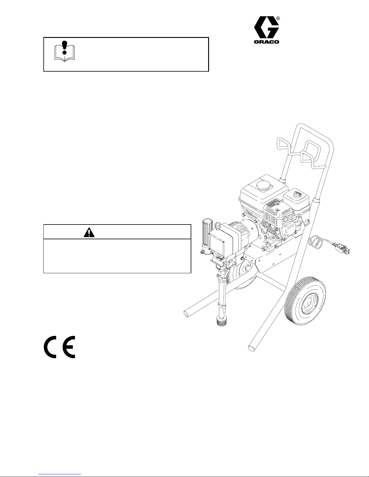
GM3000 Airless Paint Sprayer
3000 psi (210 bar, 21 MPa) Maximum Working Pressure
Model 231363, Series B
Basic Sprayer with Upright Cart
Model 231551
Same as 231363, with hose and gun, RACr X
HandTitet Tip Guard, and 517 size SwitchTipt
Model 231550, Series B
Basic Sprayer with Lo–Boy Cart
Model 231552
Same as 231550, with hose and gun, RACr X
HandTitet Tip Guard, and 517 size SwitchTipt
Rev. K
CAUTION
Always use a minimum hose length of 50 foot
(15 m) 1/4 inch ID or 50 foot (15 m) 3/8 inch ID. An
undersized hose may result in poor equipment
performance and damage to the clutch.
06001B
Model 231363 Shown
GRACO INC. P.O. BOX 1441 MINNEAPOLIS, MN 55440–1441
ECOPYRIGHT 1996, GRACO INC.
Graco Inc. is registered to I.S. EN ISO 9001
Page 2
Table of Contents
Warnings 2. . . . . . . . . . . . . . . . . . . . . . . . . . . . . . . . . . . . . .
Component Identification and Function 5. . . . . . . . . . . .
Setup 6. . . . . . . . . . . . . . . . . . . . . . . . . . . . . . . . . . . . . . . . .
Fueling 8. . . . . . . . . . . . . . . . . . . . . . . . . . . . . . . . . . . . . . . .
Startup 9. . . . . . . . . . . . . . . . . . . . . . . . . . . . . . . . . . . . . . . .
Maintenance 11. . . . . . . . . . . . . . . . . . . . . . . . . . . . . . . . . .
Flushing 12. . . . . . . . . . . . . . . . . . . . . . . . . . . . . . . . . . . . . .
Troubleshooting 14. . . . . . . . . . . . . . . . . . . . . . . . . . . . . . .
Drive Housing, Connecting Rod, Crankshaft 16. . . . . .
Pressure Control 18. . . . . . . . . . . . . . . . . . . . . . . . . . . . . .
Pinion, Clutch, Clamp, Field, & Engine 23. . . . . . . . . . .
Pinion Housing 24. . . . . . . . . . . . . . . . . . . . . . . . . . . . . . . .
Clutch 25. . . . . . . . . . . . . . . . . . . . . . . . . . . . . . . . . . . . . . .
Engine 26. . . . . . . . . . . . . . . . . . . . . . . . . . . . . . . . . . . . . . .
Field & Wiring Harness 27. . . . . . . . . . . . . . . . . . . . . . . . .
Clamp 27. . . . . . . . . . . . . . . . . . . . . . . . . . . . . . . . . . . . . . .
Symbols
Warning Symbol
WARNING
This symbol alerts you to the possibility of serious
injury or death if you do not follow the instructions.
Clutch Housing 27. . . . . . . . . . . . . . . . . . . . . . . . . . . . . . . .
Reassembly 28. . . . . . . . . . . . . . . . . . . . . . . . . . . . . . . . . .
Displacement Pump Repair 31. . . . . . . . . . . . . . . . . . . . .
Pressure Control Parts list 33. . . . . . . . . . . . . . . . . . . . . .
Upright Sprayer Parts Drawing 34. . . . . . . . . . . . . . . . . .
Upright Sprayer Parts List 35. . . . . . . . . . . . . . . . . . . . . .
Lo-Boy Sprayer Parts Drawing 36. . . . . . . . . . . . . . . . . .
Lo-Boy Sprayer Parts List 37. . . . . . . . . . . . . . . . . . . . . .
Parts List & Drawing – Complete Sprayers 38. . . . . . .
Pinion Assembly Parts list and Drawing 38. . . . . . . . . .
Accessories 39. . . . . . . . . . . . . . . . . . . . . . . . . . . . . . . . . .
Technical Data 39. . . . . . . . . . . . . . . . . . . . . . . . . . . . . . . .
Dimensions 39. . . . . . . . . . . . . . . . . . . . . . . . . . . . . . . . . . .
Graco Phone Number 39. . . . . . . . . . . . . . . . . . . . . . . . . .
Graco Warranty 40. . . . . . . . . . . . . . . . . . . . . . . . . . . . . . .
Caution Symbol
CAUTION
This symbol alerts you to the possibility of damage to
equipment if you do not follow the instructions.
INSTRUCTIONS
WARNING
EQUIPMENT MISUSE HAZARD
Equipment misuse can cause the equipment to rupture or malfunction and result in serious injury.
D This equipment is for professional use only.
D Read all instruction manuals, tags, and labels before operating the equipment.
D Use the equipment only for its intended purpose. If you are not sure, call your distributor.
D Do not alter or modify this equipment. Use only genuine Graco parts.
D Check equipment daily. Repair or replace worn or damaged parts immediately.
D Do not exceed the maximum working pressure of the lowest rated system component. Refer to the
Technical Data on page 39 for the maximum working pressure of this equipment.
D Use fluids and solvents which are compatible with the equipment wetted parts. Refer to the Tech-
nical Data section of all equipment manuals. Read the fluid and solvent manufacturer’s warnings.
D Do not use hoses to pull equipment.
D Route hoses away from traffic areas, sharp edges, moving parts, and hot surfaces. Do not expose
Graco hoses to temperatures above 82_C (180_F) or below –40_C (–40_F).
D Do not lift pressurized equipment.
D Comply with all applicable local, state, and national fire, electrical, and safety regulations.
D Wear hearing protection when operating this equipment.
D Do not use 1,1,1–trichloroethane, methylene chloride, other halogenated hydrocarbon solvents or
fluids containing such solvents in pressurized aluminum equipment. Such use could result in a
chemical reaction, with the possibility of explosion.
3086202
Page 3
WARNING
INJECTION HAZARD
Spray from the gun, leaks or ruptured components can inject fluid into your body and cause extremely
serious injury, including the need for amputation. Fluid splashed in the eyes or on the skin can also
cause serious injury.
D Fluid injected into the skin may look like just a cut, but it is a serious injury. Get immediate medi-
cal attention.
D Do not point the gun at anyone or at any part of the body.
D Do not put your hand or fingers over the spray tip.
D Do not stop or deflect leaks with your hand, body, glove or rag.
D Do not “blow back” fluid; this is not an air spray system.
D Always have the tip guard and the trigger guard on the gun when spraying.
D Check the gun diffuser operation weekly. Refer to the gun manual.
D Be sure the gun trigger safety operates before spraying.
D Lock the gun trigger safety when you stop spraying.
D Follow the Pressure Relief Procedure on page 12 if the spray tip clogs and before cleaning,
checking or servicing the equipment.
D Tighten all fluid connections before operating the equipment.
D Check the hoses, tubes, and couplings daily. Replace worn or damaged parts immediately. Do not
repair high pressure couplings; you must replace the entire hose.
D Fluid hoses must have spring guards on both ends, to help protect them from rupture caused by
kinks or bends near the couplings.
TOXIC FLUID HAZARD
Hazardous fluid or toxic fumes can cause serious injury or death if splashed in the eyes or on the skin,
inhaled, or swallowed.
D Know the specific hazards of the fluid you are using.
D Store hazardous fluid in an approved container. Dispose of hazardous fluid according to all local,
state and national guidelines.
D Always wear protective eyewear, gloves, clothing and respirator as recommended by the fluid and
solvent manufacturer.
FUEL HAZARD
The fuel used in this unit is combustible and when spilled on a hot surface can ignite and cause a fire.
D Do not fill the fuel tank while the engine is running or hot.
EXHAUST HAZARD
The exhaust contains poisonous carbon dioxide which is colorless and odorless.
D Do not operate this equipment in a closed building.
308620 3
Page 4
WARNING
FIRE AND EXPLOSION HAZARD
Improper grounding, poor ventilation, open flames or sparks can cause a hazardous condition and
result in a fire or explosion and serious injury.
D If there is any static sparking or you feel an electric shock while using this equipment, stop spray-
ing immediately. Do not use the equipment until you identify and correct the problem.
D Provide fresh air ventilation to avoid the buildup of flammable fumes from solvents or the fluid
being sprayed.
D Keep the spray area free of debris, including solvent, rags, and gasoline.
D Disconnect all electrical equipment in the spray area.
D Extinguish all open flames or pilot lights in the spray area.
D Do not smoke in the spray area.
D Do not turn on or off any light switch in the spray area while operating or if fumes are present.
D Do not operate a gasoline engine in the spray area.
D Ground the sprayer to a true earth ground with the ground wire and clamp (supplied).
D Use only electrically conductive hoses.
MOVING PARTS HAZARD
Moving parts can pinch or amputate your fingers.
D Keep clear of all moving parts when starting or operating the sprayer.
D Before servicing the equipment, follow the Pressure Relief Procedure on page 12 to prevent the
equipment from starting unexpectedly.
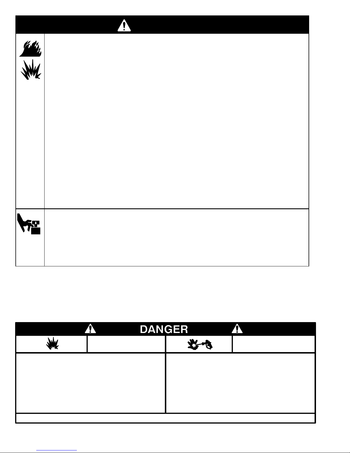
NOTE: This is an example of the DANGER label on your sprayer. This label is available in other languages, free of
charge. See page 39 to order.
FIRE AND
EXPLOSION HAZARD
Spray painting, flushing or cleaning equipment with flammable
liquids in confined areas can result in fire or explosion.
Use outdoors or in extremely well ventilated areas. Ground
equipment, hoses, containers and objects being sprayed.
Avoid all ignition sources such as static electricity from plastic
drop cloths, open flames such as pilot lights, hot objects such as
cigarettes, arcs from connecting or disconnecting power cords
or turning light switches on and off.
Failure to follow this warning can result in death or serious injury.
READ AND UNDERSTAND ALL LABELS AND INSTRUCTION MANUALS BEFORE USE
Liquids can be injected into the body by high pressure airless
spray or leaks – especially hose leaks.
Keep body clear of the nozzle. Never stop leaks with any part of the
body. Drain all pressure before removing parts.Avoid accidental
triggering of gun by always setting safety latch when not spraying.
Never spray without a tip guard.
In case of accidental skin injection, seek immediate
“Surgical Treatment”.
Failure to follow this warning can result in amputation or serious
injury.
SKIN INJECTION
HAZARD
3086204
Page 5
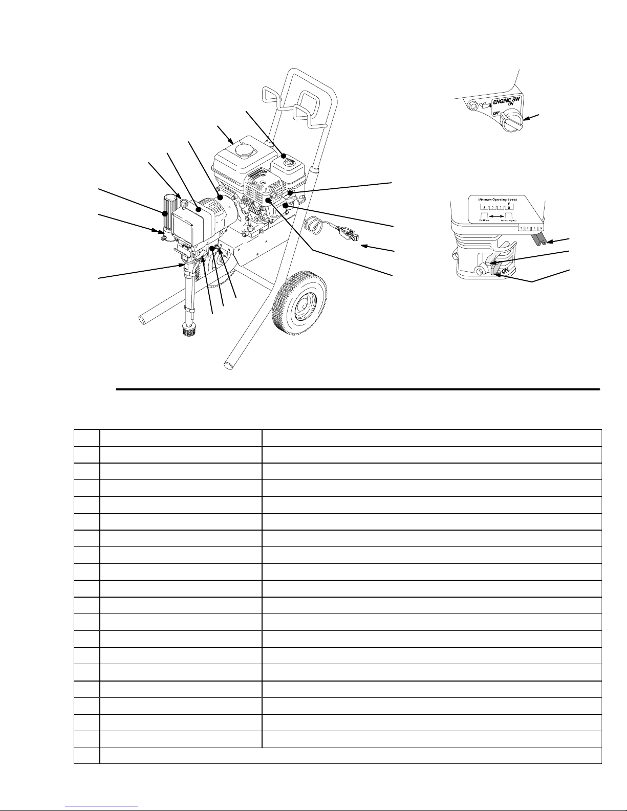
Component Identification and Function
T
L
S
Fig. 1
C
D
P
R
B
F
N
U
E
A
M
V
06001B
K
0015
J
H
G
0016
A Pressure Control Switch ON/OFF, enables/disables clutch function
B Pressure Adjusting Knob Controls fluid outlet pressure
C Air Cleaner* Filters air entering the carburetor
D Fuel Tank* Holds 0.66 gallons (2.5 liters) of [(R+M)/2]; 86 octane gasoline
E Muffler* Reduces noise of internal combustion
F Spark Plug Cable* Routes electrical current to spark plug
G Fuel Valve* On/off valve to regulate fuel flow from gasoline tank to carburetor
H Choke* Enriches air/gasoline mixture for cold starting
J Throttle* Adjusts engine speed for large or small orifice spray tips
K Engine Switch* Enables/disables engine operation
L Fluid Outlet Hose and spray gun are connected here
M Pressure Control Controls clutch cycling to maintain fluid pressure.
N Engine* 4.0 HP gasoline engine
P Clutch Transfers power from engine to drive assembly
R Drive Assembly Transfers power from clutch to displacement pump
S Displacement Pump Provides fluid to be sprayed through spray gun
T Fluid Filter Filters fluid between source and spray gun
U Grounding Clamp and Wire Grounds sprayer system
V Pressure Drain Valve Relieves fluid pressure when open
* For more detailed explanations of these controls, refer to the Honda engine manual; supplied
308620 5
Page 6
Setup
CAUTION
To avoid damaging the pressure control, which may
result in poor equipment performance and component
damage, follow these precautions.
1. Always use nylon spray hose. Never use a wire
braid hose; it is too rigid to act as a pulsation
dampener.
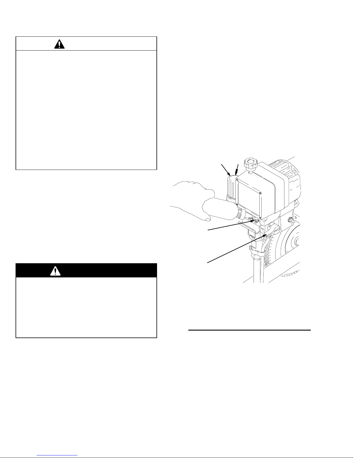
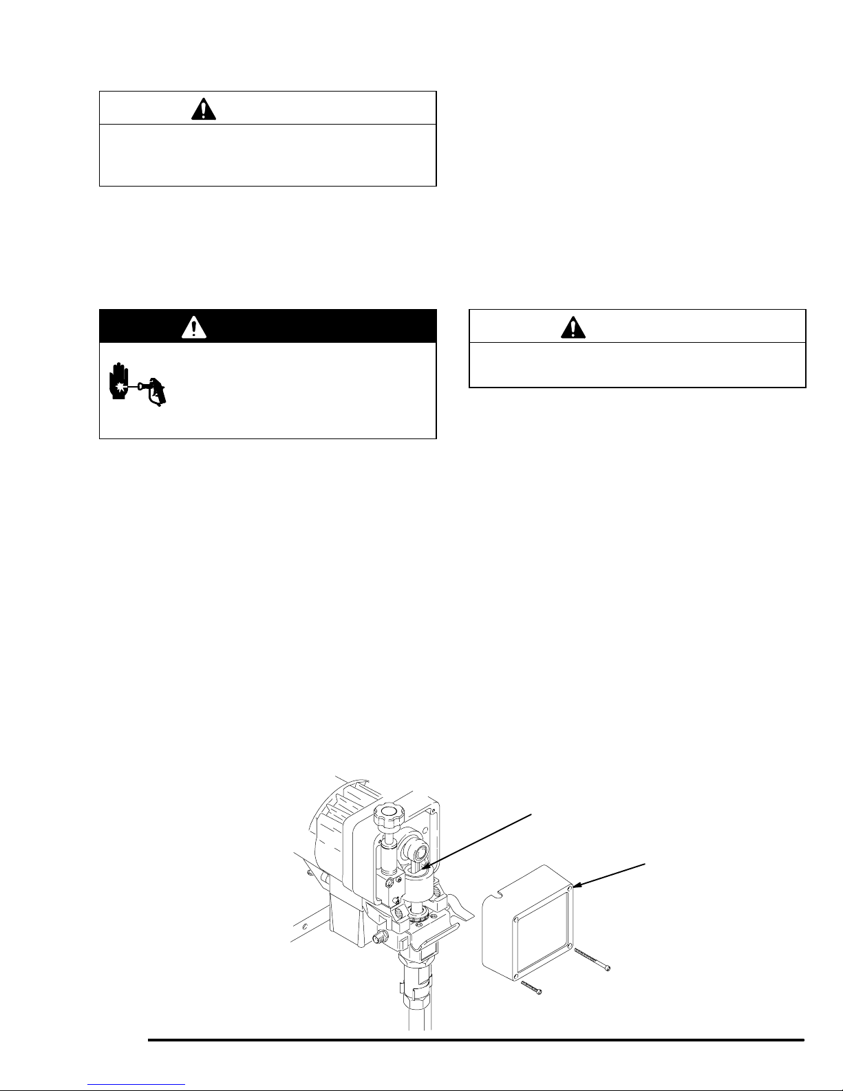
2. Fill packing nut/wetcup. Fill the packing nut/wetcup (A) 1/3 full with Graco Throat Seal Liquid
(TSL), supplied. See Fig. 2.
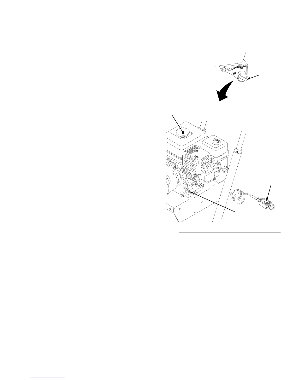
3. Check the engine oil level. Refer to the Honda
engine manual, supplied. This is a summary of the
information: Remove one of the oil fill plugs (M);
the oil should be almost overflowing. See Fig. 3.
Add oil as necessary.
2. Always use a minimum hose length of 50 foot
(15 m) x 1/4 inch ID or 50 foot (15 m) x 3/8 inch
ID hose.
3. Never install any shutoff device between the filter
(21) and the main hose. See Fig. 2.
4. Always use the main filter outlet (20) for a one
gun operation. Never plug this outlet.
1. Connect hose and gun. (Refer to Fig. 2.)
a. Remove the plastic cap from the 1/4 npsm (m)
filter outlet nipple (20). Screw the main fluid
hose onto the nipple. Read the CAUTION,
above.
b. Connect the whip end hose between the main
fluid hose and the inlet adapter of the gun.
c. Do not use thread sealant, and do not install
the spray tip yet!
WARNING
Recommended lubrication oil: Use a high-quality,
detergent oil, SAE 10W–30, classified “FOR
SERVICE SG or SF”, for regular use and for
breaking–in a new engine.
21
A
46
20
If you supply your own hoses and spray gun, be
sure the hoses are electrically conductive, that the
gun has a tip guard, and that each part is rated for
at least 3000 psi (210 bar, 21 MPa) Maximum
Working Pressure. This is to reduce the risk of
serious injury caused by static sparking, fluid
injection or over-pressurization and rupture of the
hose or gun.
3086206
21 Fluid Filter
46 Pressure drain valve
20 1/4 npsm(m) fluid outlet
A Wetcup
Fig. 2
05832
Page 7
Setup
4. Be sure your system is properly grounded
before operating it. Connect the sprayer to a true
earth ground with the grounding wire and clamp
(80) ; for example, a cold water pipe or a ground
rod driven into the earth.
5. Fill the gas tank. See Fueling, page 8.
6. Flush the pump to remove the lightweight oil
which was left in the pump to protect it from corrosion.
a. Before using water–base paint, flush with
mineral spirits, followed by soapy water, and
then flush with clean water.
b. Before using oil–base paint, flush with mineral
spirits, only.
c. See Flushing on page 13 for the flushing
procedure.
7. Prepare the paint according to the manufacturer’s
recommendations.
8. Keep the sprayer upright and level during
operation and whenever it is being moved. See the
CAUTION on page 10.
K
0015
L
a. Remove any skin that may have formed.
b. Stir the paint to mix the pigments.
c. Strain the paint through a fine nylon mesh bag
(available at most paint dealers) to remove the
particles that could clog the filter or spray tip.
This is probably the most important step
toward trouble–free spraying.
80
M
06906A
Fig. 3
308620 7
Page 8

Fueling
WARNING
FIRE AND EXPLOSION HAZARD
Gasoline is extremely flammable and
explosive under certain conditions.
Always turn the engine switch (K) to off
before refueling. (Fig. 3)
Refuel in a well-ventilated area.
Do not smoke or allow flames or sparks in the area
where the engine is refueled or where the gasoline
is stored.
Do not overfill the tank. Make sure the gas fill cap
(L) is securely closed after refueling. (Fig. 3)
2. Gasolines containing alcohol (gasohol). Do not
use gasohol which contains methanol, if the gasohol does not contain cosolvents and corrosion
inhibitors for methanol. Even if it does contain such
additives, do not use the gasohol if it contains
more than 5% methanol or 10 % ethanol.
NOTE: The Honda engine warranty does not cover
the damage resulting from the use of gasolines containing a higher percentage of alcohol than mentioned
in step 2. See the Honda engine manual for more
information.
3. General. Do not use any oil and gasoline mixtures
or contaminated gasoline. Avoid getting any dirt,
dust or water in the fuel tank.
Be careful not to spill fuel when fueling. Fuel vapor
or spilled fuel can ignite. If any fuel is spilled, make
sure the area is dry before starting the engine.
1. Fuel specifications. Use automotive gasoline
with a pump octane number of 86 or higher, or a
research octane number of 91 or higher. Unleaded
fuel minimizes the combustion chamber deposits.
4. Tank Capacity. 0.66 gallons (2.5 liters). Always
leave at least 1/2 in. (13 mm) at the top of the tank
for expansion.
5. Shut off the engine before refueling.
6. After refueling, tighten the fuel tank cap firmly.
3086208
Page 9
Startup
Before You Start the Sprayer
1. See Flushing on page 12 to determine if you
should flush the sprayer.
2. Be sure the gas tank is full.
3. Check the engine oil level.
NOTE: The engine stops automatically, or will not
start, if it is low on oil. Refer to the oil fill procedure in
the Honda engine manual or to step 3, page 6.
4. Be sure the spark plug cable is firmly pushed
onto the plug.
Starting the Sprayer
NOTE: Refer to Fig. 1 as you start the sprayer.
1. When starting a sprayer that IS NOT PRIMED,
remove the spray tip.
2. Place the suction tube into the paint, water or
solvent container, depending on whether you are
flushing or are ready to spray.
3. Open the black fuel shutoff lever by pushing it in
the direction of the arrow.
4. Move the pressure control switch to OFF.
5. To start the engine:
a. Turn the pressure adjusting knob all the way
counterclockwise to the lowest pressure setting.
b. Slide the metal throttle lever away from the
fuel tank to maximum position (fully left).
c. If the engine is cold, close the choke by mov-
ing the gray lever.
d. If the engine is warm, close the choke by
moving the gray lever only half way or not at
all.
e. Turn the engine switch to ON.
WARNING
MOVING PARTS HAZARD
A rope which recoils too quickly may hit
someone and cause serious injury. The
rope could also jam in recoil assembly.
f. Hold the frame of the sprayer with one hand
and pull the starter rope rapidly and firmly.
Continue holding the rope as you let it return.
Pull and return the rope until the engine starts.
CAUTION
Never try to start the engine unless fluid pressure is
relieved and the pressure control switch is OFF.
Trying to start the engine when it is pressurized
could damage the recoil system.
g. Open the choke as soon as the engine starts,
except in cold weather. In cold weather, leave
the choke closed for 10 to 30 seconds before
opening it to keep the engine running.
6. Unlock the gun trigger safety.
308620 9
Page 10
Startup
7. Prime the pump:
a. Place the suction tube in the bucket of paint,
water, or solvent.
b. Open the pressure drain valve.
c. Set engine speed to idle.
d. Move the pressure control switch to ON. Turn
the pressure adjusting knob slowly until the
sprayer starts.
e. Run the pump until fluid is flowing smoothly
from the pressure drain valve, indicating the
pump is primed.
f. Move the pressure control switch to OFF.
g. If the pump was primed with water or solvent,
remove the suction tube from the water or
solvent and place it in the paint. Repeat steps
b through f.
h. Close the pressure drain valve.
8. When the pump is primed:
h. Relieve pressure by opening the pressure
drain valve.
i. Close the pressure drain valve.
WARNING
INJECTION HAZARD
To reduce the risk of serious injury from
fluid injection, never operate the spray
gun with the tip guard removed.
9. Install the spray tip in the gun. See the separate
tip instruction manual, 308–644, supplied.
10. Move the pressure control switch to ON.
11. Adjust the engine speed and pump pressure.
Unlock the gun trigger safety. Trigger the gun onto
a test paper to check the spray pattern and atomization. Turn the pressure adjusting knob until you
get a good pattern. Then slowly lower the throttle
setting as far as you can without changing the
spray pattern.
a. Remove the spray tip.
b. Set the engine speed to full flow.
c. Move the pressure control switch to ON. Turn
the pressure adjusting knob slowly until the
sprayer starts.
d. Unlock the gun trigger safety.
e. Trigger the gun into the pail until fluid flows
from the gun. If pumping solvent or solvent–
based paint, hold a metal part of the gun firmly
against a grounded metal pail.
f. Release the gun trigger and lock the gun
trigger safety.
g. Move the pressure control switch to OFF.
CAUTION
Always use the lowest needed fluid pressure and the
lowest needed throttle setting, to increase the life of
the sprayer. Higher settings cause excessive clutch
cycling, premature tip wear and premature pump
wear.
CAUTION
Close the black fuel shutoff lever whenever you are
transporting the sprayer to prevent fuel from flooding
the engine.
Keep the sprayer upright and level when operating it
and when transporting it. This prevents crankcase oil
from leaking into the combustion chamber, which
makes startup very difficult.
30862010
Page 11
Startup
CAUTION
Operating the sprayer with the pump not primed can
lead to premature packing wear and/or damage to
the pump.
Maintenance
Loss of Prime to Pump
Introduction of air into the pump, either by changing
fluids or due to a suction leak, may result in the loss of
prime to the pump. If the pump loses prime, no fluid is
pumped.
To prime the pump, relieve the pressure on the system
by opening the drain valve and following the instruction
on Prime the pump, page 10.
WARNING
INJECTION HAZARD
To reduce the risk of serious injury,
whenever you are instructed to relieve
pressure, follow the Pressure Relief
Procedure on page 12.
DAILY: Check the engine oil level and fill as neces-
sary.
DAILY: Check and fill the gas tank.
AFTER THE FIRST 20 HOURS OF OPERATION
Drain the oil and refill with clean oil.
WEEKLY: Remove the cover of the air filter and
clean the element. Replace the element, if necessary.
If operating in an unusually dusty environment, check
the filter daily and replace it, if necessary.
Replacement elements may be purchased from your
local Honda dealer.
CAUTION
For detailed engine maintenance and specifications,
refer to the separate engine manual, supplied.
WEEKLY: Check the level of the TSL in the displacement pump packing nut. Fill the nut, if necessary. Keep
TSL in the nut to help prevent fluid buildup on the
piston rod and premature wear of the packings.
Monthly: Remove the front cover (9) and fill the
cavity in the connecting rod with non-detergent motor
oil 1/4 in. below the surface. See Fig. 4.
AFTER EACH 100 HOURS OF OPERATION:
Change the oil. Refer to the engine manual for additional maintenance instructions.
SPARK PLUG: Use only an (NGK) BPR6ES or a
(NIPPON DENSO) W20EPR-U plug. Gap the plug to
0.028 to 0.031 inch (0.7 to 0.8 mm). Use a spark plug
wrench when installing and removing the plug.
Fig. 4
Fill to .25 in. below surface with non-detergent
motor oil.
9
06011
308620 11
Page 12
Pressure Relief Procedure
WARNING
INJECTION HAZARD
The system pressure must be manually
relieved to prevent the system from
starting or spraying accidentally. Fluid
under high pressure can be injected through the
skin and cause serious injury. To reduce the risk of
an injury from injection, splashing fluid, or moving
parts, follow the Pressure Relief Procedure
whenever you:
D are instructed to relieve the pressure,
D stop spraying,
D check or service any of the system equipment,
D install or clean the spray tip.
Flushing
When to Flush
1. Engage the gun safety latch.
2. Turn the engine switch to OFF.
3. Move the pressure control ON/OFF switch to OFF.
4. Disengage the gun safety latch. Hold a metal part
of the gun firmly to a grounded metal pail. Trigger
the gun to relieve pressure.
5. Engage the gun safety latch.
6. Open the pressure drain valve. Leave the pressure
drain valve open until you are ready to spray
again.
7. Disconnect the spark plug cable.
If you suspect that the spray tip or hose is completely
clogged, or that pressure has not been fully relieved
after following the steps above, VERY SLOWLY
loosen the tip guard retaining nut or hose end coupling
to Relieve the pressure gradually, then loosen completely. Now clear the tip or hose.
1. New Sprayer. This sprayer was factory tested in
lightweight oil,which was left in to protect the pump
parts.
Before using water–base paint, flush with mineral
spirits, followed by a soapy water flush, and then a
clean water flush.
Before using oil–base paint, flush with mineral
spirits.
2. Changing Colors.
such as mineral spirits or water.
3. Changing from water–base to oil–base paint. Flush
with warm, soapy water, then mineral spirits.
4. Changing from oil–base to water–base paint.
with mineral spirits, followed by warm, soapy
water, and then a clean water flush.
Flush with a compatible solvent
Flush
CAUTION
To prevent pump corrosion or damage to pump
components, never leave water or any type of paint
in the sprayer when it is not in use. Pump the water
or the paint out with mineral spirits.
5. Storage.
Water base paint: flush with water, then mineral
spirits and leave the pump, hose and gun filled
with mineral spirits. Shut off the sprayer, remove
the spark plug cable, and open the pressure drain
valve to Relieve the pressure. Leave the drain
valve open.
Oil base paint: flush with mineral spirits and leave
the pump, hose and gun filled with mineral spirits.
Shut off the sprayer, remove the spark plug cable,
and open the pressure drain valve to Relieve the
pressure. Leave the drain valve open.
6. Startup after storage.
Before using water–base paint, flush out the
mineral spirits with soapy water, and then with
clean water.
When using oil–based paint, flush out the mineral
spirits with the paint to be sprayed.
30862012
Page 13

How to Flush
Flushing
WARNING
CAUTION
When changing fluids, do not drain all of the first fluid
from the suction tube before inserting the suction tube
into the another fluid. Not doing so may introduce
excessive air into the pump and cause the pump to
lose prime.
After moving the suction tube to a new fluid, pump the
first fluid and any trapped air, out through the drain
valve before beginning to pump the new fluid to the
guns.
NOTE: The word solvent refers to water or oil-based
solvent.
1. Follow the Pressure Relief Procedure, page 12.
2. Remove the filter bowl and screen; see instruction
manual 308249, supplied. Install the bowl and
support, without the screen, to flush. Clean the
screen separately.
3. Close the pressure drain valve.
4. Put the suction tube in a grounded pail of solvent.
FIRE AND EXPLOSION HAZARD
To reduce static sparking and splashing,
always remove the spray tip from the
gun, and hold a metal part of the gun
firmly to the side of a grounded metal pail when
flushing.
6. Follow Startup on page 9. Keep the gun triggered until clean solvent comes from the nozzle.
Release the trigger and lock the gun trigger safety.
CAUTION
Operation with the pump not primed can lead to
premature packing wear and damage to the pump.
7. Check all fluid connections for leaks. Relieve the
pressure before tightening any connections. Start
the sprayer. Recheck the connections for leaks.
8. Remove the suction tube from the solvent pail.
Unlock the gun trigger safety. Trigger the gun to
force solvent from the hose. Do not let the pump
run dry for more than 30 seconds, to avoid damaging the pump packings. Relieve the pressure.
9. Unscrew the filter bowl and reinstall the clean
screen. Reinstall the bowl, hand tight only.
5. Remove the spray tip from the gun.
10. Follow Storage or Changing Colors, on page 12
Relieve the pressure.
308620 13
Page 14

Troubleshooting
displ
t
WARNING
INJECTION HAZARD
To reduce the risk of serious injury,
whenever you are instructed to relieve
pressure, follow the Pressure Relief
Procedure on page 12.
Check everything in the chart before disassembling the sprayer. See pages 34 through 33 for description of
referenced parts
PROBLEM
The engine or sprayer won’t
start.
The engine won’t “pull over”. Oil is seeping into the combustion chamber. Remove the spark plug. Pull the starter rope 3
The engine operates, but the
acement pump does no
operate. The pressure setting is too low. Turn the pressure adjusting knob clockwise to
CAUSE SOLUTION
The engine switch is not on. Turn on the switch.
The engine is out of gas. Refill the gas tank. See page 8.
The engine oil level is low. Try to start the engine. Replenish the oil, if nec-
The spark plug cable is disconnected or it is
damaged
There is frozen water in the sprayer. Allow the sprayer to thaw completely before
The pressure control switch is turned off. Turn on the switch.
The fluid filter (21) is dirty. Clean the filter. See page 13.
The tip or the tip filter is clogged. Clean the tip or the tip filter. See the gun
The displacement pump rod is stuck due to
dried paint.
essary. See Step 3, page 6.
Reconnect the spark plug cable or replace the
spark plug.
starting it.
or 4 times. Clean or replace the plug. Try to
start the engine. Keep the sprayer upright to
avoid oil seepage.
increase pressure.
instruction manual.
Repair the pump. See page 31.
The connecting rod is worn or damaged. Replace the connecting rod. See page 16.
The drive housing is worn or damaged. Replace the drive housing. See page 16.
The electrical power is not energizing the field. Check the wiring connections. See page 26.
The clutch is worn, damaged, or incorrectly
positioned.
The pinion assembly is worn or damaged. Repair or replace the pinion assembly. See
30862014
With the pressure control switch turned on and
the pressure turned to maximum, use a test
light to check the power at the black and white
wires from the pressure control.
Have the pressure control checked by an authorized Graco dealer.
Replace the clutch. See page 25.
page 23.
Page 15

PROBLEM CAUSE SOLUTION
th
l
The pump output is low on
e upstroke.
The output of the pump is
ow on the downstroke or on
both of the strokes.
The paint leaks into the wetcup.
The fluid delivery is low.
The inlet screen (102) is clogged. Clean the screen.
A piston ball (121) is not seating. Service the piston ball–check. See page 31.
The piston packings are worn or damaged. Replace the packings. See page 31.
A o-ring (119) in the displacement pump is
worn or damaged.
The inlet screen (39) is clogged. Clean the screen.
The piston packings are worn or damaged. Replace the packings. See page 31.
An intake valve ball is not seating
properly.
The engine speed is too low. Increase the throttle setting. See Step 11, page
The clutch is worn or damaged. Replace the clutch. See page 25.
The wetcup is loose. Tighten the wetcup just enough to stop leak-
The throat packings is worn or damaged. Replace the packings. See page 31.
A displacement rod is worn or damaged. Replace the rod. See page 31.
The inlet screen (39) is clogged. Clean the screen.
The pressure setting is too low. Increase the pressure. See Step 11, page 10.
Replace the o-ring. See page 31.
Clean the intake valve. See page 31.
10.
age.
Fluid is spitting from the gun.
The pump is difficult to prime.
The engine speed is too low. Increase the throttle setting. See Step 11, page
The fluid filter (21), the tip filter or the tip is
clogged or dirty.
There is a large pressure drop in the hose. Use a larger diameter hose.
There is air in the pump or the hose. Check and tighten all the fluid connections.
The tip is partially clogged. Clear the tip. See the gun instruction manual.
The fluid supply is low or empty. Refill the fluid supply. Prime the pump. See
There is air in the pump or the hose. Check and tighten all the fluid connections.
The intake valve is leaking. Clean the intake valve. Be sure ball seat is not
The pump packings are worn. Replace the pump packings. See page 31.
The paint is too thick. Thin the paint according to the supplier’s
The engine speed is too high. Decrease the throttle setting before priming the
10.
Clean the filter. See page 13. Or, see the gun
instruction manual.
Reprime the pump. See page 10.
page 9. Check the fluid supply often to prevent running the pump dry.
Reduce the engine speed and cycle the pump
as slowly as possible during priming.
nicked or worn and that the ball seats well.
Reassemble the valve.
recommendations.
pump. See Step 7, page 10.
308620 15
Page 16

Drive Housing, Connecting Rod, Crankshaft
6. Remove and inspect the crankshaft (8) and the
WARNING
INJECTION HAZARD
To reduce the risk of serious injury,
whenever you are instructed to relieve
pressure, follow the Pressure Relief
Procedure on page 12.
Removal
NOTE: Inspect parts as they are removed. Replace
parts that are worn or damaged.
connecting rod (10).
Installation
7. Lubricate the inside of the drive housing bronze
bearing with SAE non-detergent oil.
8. Install the connecting rod.
1. Remove the displacement pump. See page 31.
2. Remove the pressure control (25). See page 18.
3. Remove the three drive housing screws and lock
washers (15, 16). See Fig. 5 on page 17.
4. Remove the two pinion housing screws (69) and
lock washers (16). See Fig. 5 on page 17.
5. Tap the lower rear of the drive housing (6) with a
plastic mallet to loosen the drive housing. Pull the
drive housing straight off the pinion housing.
CAUTION
Do not allow the gear (19) to fall; it may stay attached to the drive housing or to the pinion housing.
Do not lose the thrust balls (6a and 2d) or let them
fall between the gears, which will damage the drive
housing if not removed. The balls, which are heavily
covered with grease, usually stay in the housing
recesses, but could be dislodged. If the balls are not
in place, the bearings will wear prematurely.
9. Place the large washer (5) and then the small
washer (3) on the crankshaft (8).
10. Insert the crankshaft into the bearing in the drive
housing (6) and connecting rod (10).
11. If replacing the complete drive housing assembly
(6), brush G-n lubricant (supplied) on all gear
teeth. Then recoat the gear teeth with bearing
grease (supplied). Pack the remaining bearing
grease into the bottom part of the drive housing.
Use 0.22 pint of the grease. See Fig. 6.
12. Install gear (19).
13. Install new gasket (64).
14. Work backwards from step 4 to reassemble.
30862016
Page 17

Drive Housing, Connecting Rod, Crankshaft
1
69
16
2
2d
3
19
1
Torque to 100 in–lb (11 N.m)
2 Quantity of three
3
Quantity of one
25
REF A
6a
8
5
Lubricate with SAE
4
non-detergent oil
Fig. 5
4
A
68
65
23
3
9
10
26
2
15
6
16
1
64
05833B
Brush G-n lubricant
and recoat with bearing
grease
Fig. 6
Pack with bearing grease (0.22 pint)
06003
308620 17
Page 18

Pressure Control
WARNING
7. Loosely install the screws (24) and then torque
them to 21 in–lb (2.4 N.m).
INJECTION HAZARD
To reduce the risk of serious injury,
whenever you are instructed to relieve
pressure, follow the Pressure Relief
Procedure on page 12.
NOTE: See Fig. 7 for this procedure.
NOTE: The pressure control (25) cannot be repaired
or adjusted. If it has malfunctioned, replace it.
1. Remove the front cover (9). Remove the screws
(65) and lock washers (37). Lower the junction box
(63).
2. Disconnect the harness connector (A) from the
control module inside the box (63).
3. Remove the screws (24). Pull forward on the
pressure adjusting knob and tip the pressure
control (25) forward and up to detach it from the
drive housing (6).
4. Guide the harness (A) through the pinion housing
and drive housing and remove the pressure control.
8. Install the front cover (9). Connect the harness (A)
to the control module leads (B).
9. Install the junction box. Be sure no leads are
pinched against the mounting face of the pinion
housing.
25
1
24
6
9
A
B
5. Guide the harness of the new pressure control
through the drive housing and pinion housing
passages.
6. Install the new pressure control. Tip the pressure
control down and back into the drive housing (6).
Do not pinch or damage the harness (A).
Fig. 7
63
37
65
Torque to
1
21 in–lb (2.4 N.m)
06012
05834
30862018
Page 19

Control Module
WARNING
INJECTION HAZARD
To reduce the risk of serious injury,
whenever you are instructed to relieve
pressure, follow the Pressure Relief
Procedure on page 12.
NOTE: See Fig. 8 for this procedure.
1. Relieve pressure.
2. Remove the junction box screws (65) and lock
washers ( 37) and lower the junction box (63).
3. Remove screw (71) and disconnect harness
connector (A) from the control module in the
junction box.
4. Remove screws (303) and lock washers (304),
disconnect all wires.
5. Install new control module. Reconnect all wires.
6. Work backwards from step 3 to reassemble.
303 304 63
1
A
1 To pressure control switch
Fig. 8
315 314
37
65
71
68
06002
ON/OFF Switch
WARNING
INJECTION HAZARD
To reduce the risk of serious injury,
whenever you are instructed to relieve
pressure, follow the Pressure Relief
Procedure on page 12.
1. Relieve pressure.
2. Remove the junction box screws (65) and lock
washers and remove the junction box (63).
3. Remove the ring (314) and rubber boot (315).
4. Disconnect the red wires from the ON/OFF switch
and remove the switch.
5. Install the switch so the internal tab of the antirotational ring engages with the vertical groove in
the threads of the switch and the external tab
engages with the blind hole of the junction box.
6. Powder the inside of the rubber boot (315) with
talcum, then shake the excess out of the boot.
Install the nut and rubber boot and tighten.
7. Reconnect the ON/OFF switch red wires.
8. Install the junction box. Be sure no leads are
pinched against the mounting face. Also be sure
the gasket (68) is installed.
308620 19
Page 20

Pressure Transducer
WARNING
INJECTION HAZARD
To reduce the risk of serious injury,
whenever you are instructed to relieve
pressure, follow the Pressure Relief
Procedure on page 12.
NOTE: See Fig. 9 for this procedure.
1. Remove the displacement pump. See page 31.
2. Use a pull–twist motion to remove the transducer
(22) from the pump manifold.
3. Clean paint residue from the hole in the manifold;
do not scratch the surface of the hole.
4. Lightly apply oil to the o-ring of the new transducer.
5. Install the transducer in the pump manifold, while
guiding the o-ring and backup ring into place.
6. Align the holes in the transducer as shown by the
arrows in Fig. 9.
Fig. 9
22
05835A
7. Install the displacement pump. See page 32.
30862020
Page 21

Models 231550 and 231552
WARNING
Suction Hose
Lubricate
1
INJECTION HAZARD
To reduce the risk of serious injury,
whenever you are instructed to relieve
pressure, follow the Pressure Relief
Procedure on page 12.
1. Separate the drain hose (31) from the suction hose
(32).
2. Pull upward on the hose (32) while unscrewing it
from the inlet tube (40). The hose coupling (A)
threads will engage and the hose will separate
from the tube.
3. Replace the o–ring (110) if it is worn or damaged.
4. Lubricate the o–ring (110) and the inlet tube (40)
threads with light grease.
5. Align the suction hose coupling with the threads of
the inlet tube (40). Tighten the hose onto the tube at
least 4 turns to ensure that the threads have disengaged and can function as a swivel joint.
CAUTION
9
1
Fig. 10
32
110
40
A
30
31
Model 231550 Shown
06004A
Misalignment or cross-threading will damage the
parts and/or create shavings which can cause the
o–ring (110) to leak.
308620 21
Page 22

WARNING
INJECTION HAZARD
To reduce the risk of serious injury,
whenever you are instructed to relieve
pressure, follow the Pressure Relief
Procedure on page 12.
Apply thread sealant
1
Apply grease
2
to face of base
Torque into pump
3
43a
3
43b
1
43c
43d
43e
43
manifold to 140 in–lb
(16 N.m)
Handle shown
4
in closed position
4f
43g
Drain Valve
Repair
1. Unscrew the spring retainer (43h) from the valve
body. Remove the spring, washers and stem/ball.
Clean any debris from the ball or seat area.
2. If replacing the gasket (43a) or seat (43b), pry out
the gasket.
NOTE: Whenever the gasket (43a) is removed, replace it with a new one.
3. Coat the o-ring (43d) with grease. Press the stem
into the valve body. Install the spring, washers and
spring retainer into the valve body.
4. Place the seat (43b) in the valve body so the
lapped side is toward the ball. Apply a small
amount of grease to the new gasket (43a) and
install it in the valve body.
43h
2
NOTE: The gasket will protrude from the end of the
valve until the valve is tightened into pump, which
correctly seats the gasket.
44
45
Fig. 11
4
02819
46
1. Turn the handle (46) to the closed position. Drive
out the pin (45). Remove the handle.
2. Remove the base (44).
3. Unscrew the drain valve (43). The gasket (43a)
and seat (43b) will stay in the valve.
Replacement
1. Apply a small amount of thread sealant onto the
valve (43) threads. Tighten the valve into the pump
manifold to 185 in–lb (21 N.m).
2. Lightly grease the face of the base (44) and install
the base. Turn the stem so the pin hole is vertical.
3. Securely install the handle (46) and drive pin (45).
WARNING
INJECTION HAZARD
To reduce the risk of serious injury, keep
the drain valve clean. Check drain valve
operation before spraying.
30862022
Page 23

Pinion, Clutch, Clamp, Field, & Engine
If servicing clutch components only, see page 25.
If no service is needed for internal parts of pinion
housing, remove drive assembly (drive and pinion
housing) from clutch housing. See page 25.
Pinion Housing Removal
WARNING
INJECTION HAZARD
To reduce the risk of serious injury,
whenever you are instructed to relieve
pressure, follow the Pressure Relief
Procedure on page 12.
NOTE: Refer to Fig. 12 for Steps 1 to 5.
1. Follow the Pressure Relief Procedure, page 12.
2. If the drive housing has not yet been removed,
follow steps 1 through 5 of DRIVE HOUSING, on
page 16.
8. Reassemble to drive housing.
CAUTION
Do not lose the thrust ball (2d). Refer to the CAUTION on page 16 for more information
NOTE: To disassemble the pinion, go to page 24. To
disassemble more of the sprayer, go to page 25. To
reassemble the sprayer from this point, skip ahead to
Reassembly, page 30, Step 8.
See page 24.1
2
Brush with G-n lubricant.
3
Pack with bearing grease (0.08 pint)
59
16
3. Remove the two bottom screws (59) and lockwashers (16) first, then remove the top three
screws (59) and lockwashers (16).
4. Pull the pinion housing (2) away from the clutch
housing (1). The armature (51b) will come with it.
5. Pull the armature (51b) off the hub (2h**) of the
pinion housing. Also see Fig. 13.
6. If replacing the complete pinion housing assembly
(2), brush G-n lubricant (supplied) on the pinion
shaft teeth. Then recoat the pinion shaft teeth with
bearing grease (supplied). Pack the remaining
bearing grease in the bottom part of the pinion
housing. Use 0.08 pint of the bearing grease.
7. Install new gasket (64) (supplied).
2
2d
Fig. 12
51b
2
1
1
3
05836C
308620 23
Page 24

Pinion Housing
Lubricate inner and
1
outer diameters
2
Lubricate teeth
Directional
3
arrow on roller
clutch must
face the small
bearing (2n)
Lubricate exterior
4
Back of pinion
5
housing
Press fit small
6
bearing (2n)
and clutch roller
(s) here
Fig. 13
Detail A
2m
2n
1.53
6
2a
5
2c
4
2d
Repairing the Pinion (Fig. 13)
NOTE: Use a hydraulic press if you purchase the pin-
ion parts individually. Otherwise, use Repair Kit No.
223189, which includes the shaft and bearings assembled and lubricated.
If using Repair Kit 223189, follow Steps 1 to 7, below.
1. Remove the small ring (2j) from the hub (2h) and
the large ring (2k) from the bearing recess of the
housing (2a).
2. Push on front of the shaft (2f) to force the bearing
and hub assembly out of the housing (2a).
3. Press the small bearing (2n) and roller clutch (2m)
out of the pinion housing (2a). Remove the new
bearing and roller clutch from the shaft of the kit
and press it into the housing to the dimension
shown. Directional arrow of roller clutch (2m) must
face bearing (2n). See Detail A.
4. Inspect o-ring (2p) and replace if necessary.
5. Install the shaft assembly, pushing it to the shoulder of the housing (2a).
6. Install rings (2k and 2j). Ring (2k) must be installed
with bevel facing back of pinion housing.
7. Go to Reassembly, page 29, Step 7, or continue
on page 24.
2k
2b
2p
2g
1
2f
2
2m
3
4
2n
4
2e
2. Remove the small ring (2j) from the hub (2h). Remove the snap ring (2k) from the bearing recess of
the housing (2a).
KEY
A Round steel bar to
push on shaft (2f)
B Hydraulic press
C Steel bar stock
D Two steel blocks
E Press platform
A
2g
B
Fig. 14
3. Push on the front of the shaft (2f) to force the
bearing and hub assembly out of the housing (2a).
4. Using a hydraulic press, place pieces of steel
bar stock on the inner race of the large bearing
(2g) and press the shaft through the hub and bearing. See Fig. 14.
5. Apply lubricant to the parts as shown in Fig. 13.
6. Press fit the following parts:
D Small bearing (2n) and then the roller clutch
(2m), with the directional arrow facing the
small bearing, into the rear of the housing (2a).
See Detail A in Fig. 13.
2j
2h
06005
2h
C
D
E
01427
If you purchased parts separately, follow steps 1 to
9, below. Disassemble only as far as needed for the
parts being replaced.
NOTE: The old bearing (2g) will be damaged as it is
removed. Have one on hand if you need to remove it
for any reason. Always replace bearing 2g if installing
a new hub 2h.
1. To replace small bearing (2n) or roller clutch (2m),
press the old one out of the pinion housing (2a).
30862024
D Large bearing (2g) to shoulder of shaft (2f).
D Hub (2h) onto the shaft (2f) all the way to the
large bearing (2g).
7. Install the shaft assembly, pushing it to the shoulder of the housing (2a).
8. Install the rings (2k and 2j).
9. Skip ahead to Reassembly, page 30, Step 8, or
continue on page 25.
Page 25

WARNING
Clutch
3. Pull the drive assembly (D) away from the clutch
housing (1).
INJECTION HAZARD
To reduce the risk of serious injury,
whenever you are instructed to relieve
pressure, follow the Pressure Relief
Procedure on page 12.
NOTE: The clutch assembly (51) includes the arma-
ture (51b) and rotor (51a). The armature and rotor
must be replaced together so they wear evenly. A new
hub (2h) should be installed as well to ensure long
clutch life.
NOTE: If the drive assembly (D) is not yet separated
from the clutch housing (1), follow Steps 1 to 4. Otherwise, start at Step 5.
NOTE: Refer to Fig. 15 for this procedure.
1. Follow the Pressure Relief Procedure, page 12.
2. Remove the two bottom screws (59) and lockwashers (16) first, then remove the top three
screws (59) and lockwashers (16).
CAUTION
The sprayer may become out of balance with the
drive housing and pinion housing removed. Support
the rear of the cart to prevent the partially disassembled sprayer from falling over.
4. The armature (51b) will move with the drive assembly. Remove the armature from the pinion hub
(2h).
CAUTION
Examine the splined hub (2h**, Fig. 13, page 24) for
wear. Replace as needed. Follow the Pinion Housing
instructions, page 24.
5. There are two ways to remove the rotor (51a).
a. Remove the four socket head capscrews (57)
and lockwashers (16). Install two of the screws
in the threaded holes (E) in the rotor. Alternately tighten the screws until the rotor comes
off. See Fig. 15.
b. You can use a standard steering wheel puller
(A). However, two 1/4–28 x 3 or 4 in. long
screws (B) are also needed. Replace the short
screws of the steering wheel puller with the
longer screws (B). Turn the screws (B) into the
threaded holes (E) of the rotor (51a). Tighten
the capscrew (C) of the tool until the rotor
comes off. See the Detail in Fig. 15.
6. Skip ahead to Reassembly, page 30, Step 6, or
continue on page 26.
Fig. 15
59
16
2h
1
E
A
B
C
05837C
51a
16
57
51b
D
2
18
308620 25
Page 26

Engine
A
NOTE: The engine must be removed before the
Clamp and Clutch Housing can be removed.
CAUTION
The sprayer will be out of balance when the engine,
clutch housing, drive housing and pinion housing are
removed. Support the rear of the cart to prevent the
partially disassembled sprayer from falling over.
CAUTION
The sprayer will experience poor clutch life if a
replacement engine is purchased from another
vendor. The engine for this sprayer is manufactured
by Honda to a special Graco specification.
1. Working under the mounting plate (A), remove the
two lock nuts (78) and then pull the screws (77)
out of the base of the engine. Remove the screw
(61). Disconnect the red wire (B) from the engine
lead (D). Disconnect the black and white wires
from the field. Pull the cable (E) carefully through
the grommet (50) before removing the engine. See
Fig. 16 and 17.
1
D
50
77
2. Lift the engine carefully and place it on a work
bench.
3. Remove the Field and Wiring Harness, Clamp
and Clutch Housing, as instructed on page 27.
NOTE: All service to the engine must be performed by
an authorized Honda dealer.
1
To engine alternator.
50
WHITE
BLACK
1
B
RED
E
78, 87
86
50
D
61
Fig. 17
A
78
06903
Fig. 16
Bottom View of Engine and Cart
30862026
06006
Page 27

Field & Wiring Harness
NOTE: Refer to Fig. 18.
1. Back out the four setscrews (58) holding the field
(53) to the clutch housing (1) approximately 3
turns.
1
2. Pull out the field. The field fits closely to the clutch
housing and must be removed carefully to prevent
jamming.
3. Pull the plastic caps (B) off the wire screws (79) in
both places on the field. Remove the screws and
remove the wire (A).
4. Skip ahead to Reassembly, page 28, Step 4 or
continue on page 27.
Clamp
NOTE: A standard steering wheel puller and two
1/4–28 x 3 or 4 in. long screws are required to remove
the clamp.
NOTE: Refer to Fig. 19.
1. Loosen the two screws (57) on the clamp (55),
working through the slot at the bottom of the clutch
housing (1).
Fig. 18
1
A
B
C
53
79
58
A
B
05839
2. Install two screws (B) of the tool (A) in two of the
threaded holes in the clamp (55). Tighten the
screw (C) until the clamp comes off.
3. Skip ahead to Reassembly, page 28, Step 2, or
continue below.
Clutch Housing
NOTE: Refer to Fig. 20.
CAUTION
If the clutch housing is removed from the engine a
special alignment tool is required to reinstall it.
1. Remove the four capscrews (83) and lockwashers
(84) which hold the clutch housing (1) to the engine.
2. Remove the engine key (56).
3. Pull off the clutch housing (1).
4. Skip ahead to Reassembly, page 28, Step 1.
Fig. 19
Fig. 20
55
57
05840
56
1
84
83
05841A
308620 27
Page 28

Reassembly
0
CAUTION
The sprayer will be out of balance when only the
engine and clutch housing are installed. Support the
rear of the cart to prevent the sprayer from falling
over.
1. Install the clutch housing (1), capscrews (83) and
lockwashers (84) on the engine. Use special
alignment tool to position clutch housing on engine. Torque screws (83) to 200 in-lb (22 Nm).
2. Install the engine shaft key (56). See Fig. 21.
3. Press the clamp (55) onto the engine shaft (A).
Maintain the 1.41 inch 0.01 (35.8 0.25 mm)
dimension shown in Fig. 22.
Torque the screws oppositely and
1
evenly to 25 in–lb (2.8 N@m).
2
Slot.
Torque the screws to 200 in–lb (22
3
N@m).
Apply low strength thread locker to set
4
screws (58).
Torque the screws to 120 in–lb (14 N@m).
5
To check the dimension, place a rigid, straight
steel bar (B) across the face of the clutch housing
(1). Use an accurate measuring device to measure
the distance between the bar and the face of the
clamp. Adjust the clamp as necessary. Torque the
two screws (57) to 120 in–lb (14 N.m).
4. Connect the wires of the harness (D) with the
screws (79) in both places on the field (wires can
be attached to either connection). Pull the plastic
caps (C) up and snap them over the screws. Install
the field in the clutch housing. Push the wire
harness through the slot in the clutch housing.
Align the setscrew holes in the field and the clutch
housing (1). Hand tighten the setscrews (58)
oppositely and evenly. See Fig. 21.
56
Fig. 21
53
55
84
3
83
A
57
58
1
2
5
1
4
D
C
79
05842A
30862028
Page 29

The face of the housing.
1
2
1.41 ".010 inch (35.8 ".25 mm).
3
Torque the screws to
120 in–lb (14 N.m).
1
1
B
Reassembly
The sprayer will be out of balance when only the
engine and clutch housing are installed. Support the
rear of the cart to prevent the sprayer from falling
over.
5. Place the engine (48) assembly on the cart. Align
the mounting holes. Carefully guide the engine
wire and wiring harness (E) from the field, through
the appropriate grommets (50) in the mounting
plate (A). Install the flange screws (77) and locknuts (78). Install the screw (61). Tighten all three
screws. Connect the engine wire to the red wire
(B), and connect the black and white wires as
shown in the Detail drawing in Fig. 16.
58
2
3
CAUTION
Fig. 22
05078
308620 29
Page 30

Reassembly
6. Be sure the face of the rotor (51a) and the clamp
(55) are free of all burrs. Install the rotor, lockwashers (16) and capscrews (57). Torque the
capscrews to 7 ft–lb (9.5 N.m). See Fig. 23.
7. After installing the rotor (51a) the air gap must be
adjusted between the rotor and the field (53).
Tighten the setscrews (58) oppositely and evenly.
Pull the engine recoil rope to assure that the
engine turns freely, and there is no contact between the rotor and the field. If there is contact,
loosen the setscrews and reposition the field.
NOTE: With the autogap style armature, the gap between the rotor and the armature is critical for proper
operation. The clutch kits with an autogap style armature include a cardboard spacer (p/n 186857) to set
the proper gap. This spacer is for use only
during
installation.
1
Torque the screw to 7 ft–lb (9.5 N.m).
The face must be clean.
2
To engine alternator.
3
4
Spline
5
Chamfered end of hub (2h)
Apply low strength thread locker.
6
Torque to 100 in.-lb (Nm).
7
2h
5
8. Clean the face of the armature (51b). With the flat
side of the armature facing the rotor (51a), slide
the armature onto the hub (2h) in the drive/pinion
assembly (D) just until the chamfered end of the
hub (2h) protrudes through the armature. See
Detail B, Fig. 23. There will be significant resistance. Attach the cardboard spacer, supplied with
the clutch kit, to the face of the armature. Bend
tabs over outside diameter of armature.
Brace the cart against a wall to keep it from rolling.
Push the drive/pinion assembly onto the clutch
housing (1). There will be significant resistance.
When the mating surfaces of the drive/pinion assembly and the clutch housing (1) are flush, remove the drive/pinion assembly. Remove the
cardboard spacer.
9. Assemble the drive assembly (D) to the clutch
housing (1), using the capscrews (59) and lockwashers (16). See Fig. 23.
48
6
58
7
59
16
06007
Detail B
Fig. 23
52
1
2
51a
16
1
57
2
51b
D
53
50
77
4
61
05843C
A
78
05843B
30862030
Page 31

Displacement Pump Repair
WARNING
INJECTION HAZARD
To reduce the risk of serious injury,
whenever you are instructed to relieve
pressure, follow the Pressure Relief
Procedure on page 12.
NOTE: Packing Repair Kit 235703 is available. Refer-
ence numbers of parts included in the kit are marked
with an asterisk, i.e., (121*). For the best results, use
all the new parts in the kit, even if the old ones still look
good.
Removing the pump (See Fig. 24.)
1. Flush the pump, if possible. Relieve pressure. Stop
the pump with the piston rod (107) in its lowest
position, if possible.
2. Remove the filter (21).
3. Remove suction hose or tube (40).(For suction
hose, refer to page 21.
NOTE: If repairing only the intake valve assembly, go
to Intake valve repair, in manual 308190.
NOTE: To minimize down time, and for the best sprayer
performance, clean the transducer (see page 20) whenever you repack the pump. Replace these parts as needed.
21
9
107
1
17
12
4. Use a screwdriver to push the retaining spring (12)
up and push out the pin (11).
5. Loosen the screws (17). Remove the pump (18).
11
18
30
120
*122
*121
*119
Fig. 24
118
Torque to
40
2
39
1
50 ft–lb (68 N.m)
2
Apply sealant
Model 231363 Shown
05844
308620 31
Page 32

Displacement Pump Repair
8
Repairing the pump
See manual 308190 for pump repair instructions.
Installing the pump (See Fig. 24 and 25.)
1. Mount the pump on the drive housing. Tap it into
the alignment pins with a soft hammer. Tighten the
screws (17) to 50 ft-lb (68 N.m).
WARNING
MOVING PARTS HAZARD
Be sure the retaining spring (12) is firmly
in the groove all the way around, to
prevent the pin (11) from working loose
due to vibration. See Fig. 25.
If the pin works loose, it or other parts could break
off due to the force of the pump action. These parts
could be projected into the air and result in serious
injury or property damage, including the pump
connecting rod or drive housing.
2. Align the hole in the rod (107) with the connecting
rod assembly (10). Use a screwdriver to push the
retaining spring (12) up and push in the pin (11).
Push the retaining spring (12) into place around
the connecting rod.
3. Reconnect the suction and drain hoses. Install the
front cover (9). On The lo-boy sprayer inspect the
o-ring (110). Replace the o-ring if it is worn or
damaged.
4. Tighten the packing nut (102) just enough to stop
leakage, but no tighter. Fill the packing nut/wet-cup
1/3 full with Graco TSL. Push the plug (123) into
the wet-cup.
11
10
17
12
102
1
123
Torque to
1
50 ft–lb (68 N.m)
Fig. 25
0600
30862032
Page 33

Pressure Control Parts List
238672 Pressure Control for the GM3000 Sprayers
Ref
No. Part No. Description Qty
301 280340 HOUSING, box, junction 1
302 238660** TRIAC 1
303 100035 SCREW, panhead, 10–24 x 2 inch 2
304 157021** LOCKWASHER, No. 10 3
305 108783** SCREW. filhd, 1
306 100284** NUT, hex 1
307 107070** SCREW, flat hd 2
308 103181** LOCKWASHER 2
309 100072** NUT, hex 2
310 111936** RECTIFIER, bridge 1
Parts Drawing –
Pressure Control
310**
316
71
303
304
301
305**
312**
2
Ref
No. Part No. Description Qty
311 238676 CONDUCTOR, electrical 1
312** 191242 PLATE, module 1
313 105679 SWITCH, toggle 1
314 105658 RING, locking 1
315 105659 BOOT, toggle 1
316 238791 CONDUCTOR, electrical 1
**Included in Repair Kit No. 238661.
Y Replacement Danger and Warning labels, tags, and
cards are available free.
Wiring Schematic –
Pressure Control
To Microswitch
304** 306**
307**
302**
308** 309**
314
315
1
1 To pressure control switch
2 Apply thermopaste between 301 and 312;
310 and 312; 302 and 312
37
65
313
311
68
06002
311
RED
313
302
RED
GROUND
GREEN
-
+
To Microswitch
310
WHITE BLACK
06010
308620 33
Page 34

Model 231363
21
Upright Sprayer Parts Drawing
69
16
1
24
25
7
1
67
8a
3
2d
DETAIL
8b
19
8
29
47
20
27
23
26
75
76
74
73
11
10
15
16
6a
2
68
63
3
37
9
12
64
65
37
6
1
22
90
1
20
92
91
17
59
58
44
45
46
56
66
48
28
2
77
81
50
13
14
18
30
40
39
16
51a
53
54
55
43
31
32
33
83
84
16
1
57
51b
3
85
16
57
79
78
80
89
1
1
Label
2
See the detail, above.
3
See page 38 for the parts.
30862034
61
38
49
34
35 36
05846D
Page 35

Upright Sprayer Parts List
Model 231363, Series A
Ref.
No. Part No. Description Qty.
1 191207 HOUSING, clutch 1
2 238684 HOUSING, pinion 1
See page 38 for parts
6 238691 DRIVE HOUSING 1
6a 100069 BALL 1
7 176904 LABEL, designation 1
8 235558 CRANKSHAFT 1
8a 180131 BEARING, thrust 1
8b 107434 BEARING, thrust 1
9 187789 COVER, front, blue 1
10 218359 CONNECTING ROD 1
11 176818 PIN, headless, 3/8” dia. x 1” 1
12 176817 SPRING, retaining 1
13 112777 SCREW, mach, ovl hd, 10–24 x .375 2
14 190321 HANGER, pail 1
15 103345 SCREW, socket head, 3
1/4–20 x 1–1/4”
16 105510 LOCKWASHER, 1/4” 16
17 111706 CAPSCREW, 7/16–14 x 1–3/4” 2
18 235699 PUMP, displacement 1
See manual 308190 for parts
19 238802 GEAR REDUCER 1
20 162453 NIPPLE, hex, 1/4 npsm x 2
1/4 npt, 1–3/16”
21 239425 FILTER, fluid 1
See Manual 308249 for parts
22 235009 PRESSURE TRANSDUCER 1
23 114415 SCREW, filh, 8–32 x 1–1/4” 1
24 114416 SCREW, filh, 10–24 x 1–5/8” 2
25 238799 SWITCH, pressure control 1
26 111705 SCREW, filh, 8–32 x 2–1/2” 3
27 290364 LABEL, identification, front 1
28 238187 HANDLE & HOSE RACK 1
29 192027 SLEEVE 2
30 108982 CONNECTOR, tube 1
31 181102 CLIP, spring 1
32 186549 DRAIN TUBE 1
33 186245 CLIP, spring 1
34 106062 WHEEL, semi–pneumatic 2
35 101242 RING, retaining, wheel 2
36 104811 HUBCAP 2
37 100020 WASHER 4
38 108691 PLUG, tubing 2
39 183770 STRAINER, inlet, 1/2–14 npsm 1
40 192169 TUBE, suction 1
43 235014 DRAIN VALVE 1
See Fig.11
43a 111699 GASKET 1
43b 187615 SEAT 1
43c 187621 HOUSING, valve, drain 1
43d 168110 O-RING 1
43e 224968 STEM, valve, drain 1
43f 111599 WASHER, flat 1
43g 187623 SPRING, compression 1
Ref.
No. Part No. Description Qty.
43h 187622 RETAINER, spring, valve 1
44 224807 BASE, valve 1
45 111600 PIN, grooved, 3/32 x 1” 1
46 187625 HANDLE, drain valve 1
47 100721 PLUG, pipe, headless, 1/4–18 nptf 1
48 108879 ENGINE, gasoline 1
49 239422 CART 1
50 109099 BUSHING, snap 2
51 238798 CLUTCH ASSEMBLY 1
51a ROTOR, clutch 1
51b ARMATURE, clutch 1
53 238803 FIELD, clutch 1
54 108800 PIN, dowel, 5/16 x 1” 1
55 188426 CLAMP, mounting, rotor 1
56 183401 KEY, parallel, 3/16” sq x 7/8” 1
57 108803 CAPSCREW, hex sch, 1/4–28 x 1.0” 6
58 108801 SETCREW, 1/4” 4
59 100644 CAPSCREW, sch, 1/4–20 x 3/4” 5
61 113802 CAPSCREW, hex hd, 3/8–16 x 5/8” 1
63 238672 PRESSURE CONTROL 1
64 191258 GASKET, housing 1
65 111703 SCREW, filh, 10–24 x 3” 4
66 189919 PLATE, designation 1
67 290228 LABEL, caution 1
68 187963 GASKET 1
69 100643 SCREW, socket head, 1/4–20 x 1” 2
71 110637 SCREW, 10–24 X 3/8” 1
72 290061 LABEL, warning 1
73 109032 SCREW, recess pnh,
self–tap “F”, No. 10–24 x 1/4” 4
74 112827 BUTTON, snap 2
75 183350 WASHER, plain, 0.90” 2
76 108068 PIN, spring, straight, 3/16” 2
77 110837 SCREW, serrated flange, hex hd,
5/16–18 unc–2a x 1.5” 2
78 110838 LOCKNUT, heavy hex, 5/16–18 3
79 109033 SCREW, bdgh, 6–32 x 3/16” 2
80 237686 GROUNDING CLAMP & WIRE 1
81 112798 SCREW, mach thd, 1/4–20 x 0.375 1
See Pressure Control Parts, page 33
83 109031 CAPSCREW,1/2 sch, 5/16–24 x 1” 4
84 104008 LOCKWASHER 4
85 221183 CONDUCTOR, electrical 1
86 108868 CLAMP, wire 1
See Fig. 16
87 101344 SCREW, cap, 5/16–18 x 7/8” 1
See Fig. 16
89 LABEL, warning, See page 39 1
90 181867 LABEL, warning 1
91 192014 PLATE, indicator 1
92 113684 RIVET, blind 2
Y Extra warning labels available free of charge.
308620 35
Page 36

Lo-Boy Sprayer Parts Drawing
Model 231550, Series A
REF 31
REF 32
21
47
20
9
23
27
1
26
110
11
32
40
12
20
3
33
109
24
10
51b
25
15
57
16
17
16
39
18
67
7
1
1
22
51a
8a
31
30
53
54
69
16
3
2d
8b
19
8
DETAIL
29
74
3
6a
64
2
68
63
37
65
75
76
73
37
6
1
43
55
44
45
83
84
90
46
56
58
59
16
2
1
92
91
28
48
77
81
66
1
50
80
57
16
85
89
1
79
78
Label
1
2
See the detail, above.
3
See page 38 for parts
30862036
61
38
49
34
35 36
05980D
Page 37

Lo-Boy Sprayer Parts List
Model 231550, Series A
Ref.
No. Part No. Description Qty.
1 191207 HOUSING, clutch 1
2 238684 HOUSING, pinion 1
See page 38 for parts
6 238656 DRIVE HOUSING 1
6a 100069 BALL 1
7 176904 LABEL, designation 1
8 235558 CRANKSHAFT 1
8a 180131 BEARING, thrust 1
8b 107434 BEARING, thrust 1
9 187789 COVER, front, blue 1
10 218359 CONNECTING ROD 1
11 176818 PIN, headless, 3/8” dia. x 1” 1
12 176817 SPRING, retaining 1
15 103345 SCREW, socket head, 3
1/4–20 x 1–1/4”
16 105510 LOCKWASHER, 1/4” 16
17 111706 CAPSCREW, 7/16–14 x 1–3/4” 2
18 235699 PUMP, displacement 1
See manual 308190 for parts
19 238802 GEAR REDUCER 1
20 162453 NIPPLE, hex, 1/4 npsm x 2
1/4 npt, 1–3/16”
21 239425 FILTER, fluid 1
See Manual 308249 for parts
22 235009 PRESSURE TRANSDUCER 1
23 114415 SCREW, filh, 8–32 x 1–1/4” 1
24 114416 SCREW, filh, 10–24 x 1–5/8” 2
25 238799 SWITCH, pressure control 1
26 111705 SCREW, filh, 8–32 x 2–1/2” 3
27 290364 LABEL, identification, front 1
28 238187 HANDLE & HOSE RACK 1
29 192027 SLEEVE 2
30 108982 CONNECTOR, tube 1
31 191640 TUBE, drain 1
32 191619 TUBE, suction 1
33 178342 CLIP, spring 2
34 106062 WHEEL, semi–pneumatic 2
35 101242 RING, retaining, wheel 2
36 104811 HUBCAP 2
37 100020 WASHER 6
38 108691 PLUG, tubing 2
39 235004 STRAINER, inlet, 3/4–16 unf 1
40 187627 TUBE, suction 1
43 235014 DRAIN VALVE 1
See Fig.11
43a 111699 GASKET 1
43b 187615 SEAT 1
43c 187621 HOUSING, valve, drain 1
43d 168110 O-RING 1
43e 224968 STEM, valve, drain 1
43f 111599 WASHER, flat 1
43g 187623 SPRING, compression 1
43h 187622 RETAINER, spring, valve 1
44 224807 BASE, valve 1
Ref.
No. Part No. Description Qty.
45 111600 PIN, grooved, 3/32 x 1” 1
46 187625 HANDLE, drain valve 1
47 100721 PLUG, pipe, headless, 1/4–18 nptf 1
48 108879 ENGINE, gasoline 1
49 238685 CART 1
50 109099 BUSHING, snap 2
51 238798 CLUTCH ASSEMBLY 1
51a ROTOR, clutch 1
51b ARMATURE, clutch 1
53 238803 FIELD, clutch 1
54 108800 PIN, dowel, 5/16 x 1” 1
55 188426 CLAMP, mounting, rotor 1
56 183401 KEY, parallel, 3/16” sq x 7/8” 1
57 108803 CAPSCREW, hex sch, 1/4–28 x 1.0” 6
58 108801 SETCREW, 1/4” 4
59 100644 CAPSCREW, sch, 1/4–20 x 3/4” 5
61 113802 CAPSCREW, hex hd, 3/8–16 x 5/8” 1
63 238672 PRESSURE CONTROL 1
64 191258 GASKET, housing 1
65 111703 SCREW, filh, 10–24 x 3” 4
66 189919 PLATE, designation 1
67 290228 LABEL, caution 1
68 187963 GASKET 1
69 100643 SCREW, socket head, 1/4–20 x 1” 2
71 110637 SCREW, 10–24 X 3/8” 1
72 290061 LABEL, warning 1
73 109032 SCREW, recess pnh,
self–tap “F”, No. 10–24 x 1/4” 4
74 112827 BUTTON, snap 2
75 183350 WASHER, plain, 0.90” 2
76 108068 PIN, spring, straight, 3/16” 2
77 110837 SCREW, serrated flange, hex hd,
5/16–18 unc–2a x 1.5” 2
78 110838 LOCKNUT, heavy hex, 5/16–18 3
79 109033 SCREW, bdgh, 6–32 x 3/16” 2
80 237686 GROUNDING CLAMP & WIRE 1
81 112798 SCREW, mach thd, 1/4–20 x .375 1
See Pressure Control Parts, page 33
83 109031 CAPSCREW,1/2 sch, 5/16–24 x 1” 4
84 104008 LOCKWASHER 4
85 221183 CONDUCTOR, electrical 1
86 108868 CLAMP, wire 1
See Fig. 16
87 101344 SCREW, cap, 5/16–18 x 7/8” 1
See Fig. 16
89 LABEL, warning, See page 39 1
90 181867 LABEL, warning 1
91 192014 PLATE, indicator 1
92 113684 RIVET, blind 2
109 103473 CLAMP, cable 2
110 104938 O-RING 1
Y Extra warning labels available free of charge.
308620 37
Page 38

Parts List & Drawing – Complete Sprayers
Models 231551 and 231552
GM3000 Airless Paint Sprayer
Includes items 201 to 204
Ref
No. Part No. Description Qty
201 231363 GM3000 Upright Sprayer
See parts list on page 35 1
231550 GM3000 Lo-Boy Sprayer
See parts list on page 37 1
202 240794 HOSE, grounded, nylon; 1/4 in. ID;
cpld 1/4 npsm(fbe); 50 foot (15 m);
spring guards both ends 1
203 238358 HOSE, grounded, nylon; 3/16 in. ID;
cpld 1/4 npsm(m) x 1/4 npsm(f) swivel;
3 foot (0.9 m); spring guards both ends 1
204 246220 CONTRACTOR II SPRAY GUN
Includes RACr X HandTite
and 517–size SwitchTip
See 309639 for parts 1
t Tip Guard
t
202
204
Pinion Assembly Parts List and Drawing
Assembly 238684
Ref
No. Part No. Description Qty
Ref
No. Part No. Description Qty
203
0160
2a 191208 .PINION HOUSING 1
2b 105489 .PIN 2
2c 102873 .BEARING 1
2d 100069 .BALL 1
2e 107394 .BEARING 1
2f** 185916 .PINION SHAFT 1
2g** 109002 .BALL BEARING, large 1
2h** 183515 .HUB, armature 1
2p
2a
2l**
2c
2j** 108880 .RETAINING RING, small 1
2k 113094 .RETAINING RING, large 1
2l** 191258 .GASKET, housing 1
2m** 110607 .CLUTCH, roller 1
2n** 109001 .BEARING, needle 1
2p** 165295 .O-RING 1
**Included in Repair Kit No. 223189.
2b
2k
2f**
2m**
2n**
2j**
2h**
2g**
2e
2d
30862038
06009
Page 39

Accessories
Displacement Pump Repair Kit 235703
Parts included in the kit are shown in manual 308190.
Hose 1/4 in. x 50 ft 240794
1/4–18 npsm female swivel, both ends.
Contractor II Spray Gun 246220
RACr X HandTitet Tip Guard 246215
Safety feature that reduces the risk of injection injury.
Technical Data
Honda GX120 Engine
Power Rating @ 3600 rpm
ANSI 4.0 Horsepower. . . . . . . . . . . . . . . . . . . . . . . . . . . . . .
DIN 6270B/DIN 6271
NA 2.1 Kw – 2.8 Ps. . . . . . . . . . . . . . . . . . . . . . . . . . . . . . .
NB 2.6 Kw – 3.6 Ps. . . . . . . . . . . . . . . . . . . . . . . . . . . . . . .
Maximum working pressure 3000 psi (210 bar, 21 MPa). . . .
Noise level
Sound power 102 dB(A). . . . . . . . . . . . . . . . . . . . . . . . . . . . . .
(per ISO–3744)
Sound pressure 87 dB(A. . . . . . . . . . . . . . . . . . . . . . . . . . . . . .
Measured at 3.1 feet (1 m) under maximum operating
conditions
Cycles/gallon (liter) 540 (142). . . . . . . . . . . . . . . . . . . . . . . . . . .
Maximum delivery 0.62 gpm (2.35 liter/min). . . . . . . . . . . . . . .
Fuel tank capacity 0.66 gallons (2.5 liter). . . . . . . . . . . . . . . . .
DANGER LABELS
The English language DANGER label shown on
page 4 is on your sprayer. If you have painters who
do not read English, order one of the following labels
to apply to your sprayer. The drawing below shows
the best placement of these labels for good visibility.
Order the labels directly from Graco, free of
charge. Toll Free: 1–800–328–0211
French 187784
Spanish 185962
German 186042
Greek 186046
Korean 186047
English 187791
Maximum tip size 0.025 @ 2000 psi . . . . . . . . . . . . . . . . . . . . .
Inlet paint strainer 12 mesh. . . . . . . . . . . . . . . . . . . . . . . . . . . . . .
Outlet paint filter 60 mesh (250 micron). . . . . . . . . . . . . . . . . . .
Pump inlet size 1/2 in. npt (f). . . . . . . . . . . . . . . . . . . . . . . . . . . .
Fluid outlet size 1/4 in. npsm from fluid filter. . . . . . . . . . . . . . .
Wetted parts
Displacement Pump stainless steel, carbon steel,. . . . . . .
Filter aluminum, carbon steel, stainless steel. . . . . . . . . . .
Pressure Control stainless steel, brass. . . . . . . . . . . . . . . . .
Suction Hose Nitrile (synthetic rubber)with nylon lining. . . .
NOTE:
Company.
rDelrinr is a registered trademark of the DuPont
(137 bar, 13.7 MPa) with latex
stainless steel screen, reusable
stainless steel screen, reusable
polyurethane, uhmw polyethylene,
aluminum, PTFE,
Apply other
language here
rDelrinr, leather
05849
Dimensions
Models 231363 & 231550
Weight
(dry w/o packaging)
Height 30 in. (762 mm)
Length 28 in. (711 mm)
Width 22 in. (589 mm)
94 lb (43 kg)
Graco Phone
Number
TO PLACE AN ORDER, contact your Graco distributor, or call this number to identify the distributor closest
to you: 1–800–690–2894 Toll Free
308620 39
Page 40

Graco Warranty
Graco warrants all equipment listed in this manual which is manufactured by Graco and bearing its name to be free from defects in
material and workmanship on the date of sale by an authorized Graco distributor to the original purchaser for use. With the exception of
any special extended or limited warranty published by Graco, Graco will, for a period of twelve months from the date of sale, repair or
replace any part of the equipment determined by Graco to be defective. This warranty applies only when the equipment is installed,
operated and maintained in accordance with Graco’s written recommendations.
This warranty does not cover, and Graco shall not be liable for general wear and tear, or any malfunction, damage or wear caused by
faulty installation, misapplication, abrasion, corrosion, inadequate or improper maintenance, negligence, accident, tampering, or
substitution of non-Graco component parts. Nor shall Graco be liable for malfunction, damage or wear caused by the incompatibility of
Graco equipment with structures, accessories, equipment or materials not supplied by Graco, or the improper design, manufacture,
installation, operation or maintenance or structures, accessories, equipment or materials not supplied by Graco.
This warranty is conditioned upon the prepaid return of the equipment claimed to be defective to an authorized Graco distributor for
verification of the claimed defect. If the claimed defect is verified, Graco will repair or replace free of charge any defective parts. The
equipment will be returned to the original purchaser transportation prepaid. If inspection of the equipment does not disclose any defect
in material or workmanship, repairs will be made at a reasonable charge, which charges may include the costs of parts, labor, and
transportation.
Graco’s sole obligation and buyer’s sole remedy for any breach of warranty shall be as set forth above. The buyer agrees that no other
remedy (including, but not limited to, incidental or consequential damages for lost profits, lost sales, injury to person or property, or any
other incidental or consequential loss) shall be available. Any action for breach of warranty must be brought within two (2) years of the
date of sale.
GRACO MAKES NO WARRANTY, AND DISCLAIMS ALL IMPLIED WARRANTIES OF MERCHANTABILITY AND FITNESS FOR
A PARTICULAR PURPOSE IN CONNECTION WITH ACCESSORIES, EQUIPMENT, MATERIALS OR COMPONENTS SOLD BUT
NOT MANUFACTURED BY GRACO. These items sold, but not manufactured by Graco (such as electric motors, gas engines,
switches, hose, etc.), are subject to the warranty, if any, of their manufacturer. Graco will provide purchaser with reasonable assistance
in making any claim for breach of these warranties.
In no event will Graco be liable for indirect, incidental, special or consequential damages resulting from Graco supplying equipment
hereunder, or the furnishing, performance, or use of any products or other goods sold hereto, whether due to a breach of contract,
breach of warranty, the negligence of Graco, or otherwise.
FOR GRACO CANADA CUSTOMERS
The parties acknowledge that they have required that the present document, as well as all documents, notices and legal proceedings
entered into, given or instituted pursuant hereto or relating directly or indirectly hereto, be drawn up in English. Les parties
reconnaissent avoir convenu que la rédaction du présente document sera en Anglais, ainsi que tous documents, avis et procédures
judiciaires exécutés, donnés ou intentés à la suite de ou en rapport, directement ou indirectement, avec les procédures concernées.
ADDITIONAL WARRANTY COVERAGE
Graco does provide extended warranty and wear warranty for products described in the “Graco Contractor Equipment Warranty
Program”.
All written and visual data contained in this document reflect the latest product information available at the time of publication.
Graco reserves the right to make changes at any time without notice.
International Offices: Belgium, Korea, Hong Kong, Japan
GRACO INC. P.O. BOX 1441 MINNEAPOLIS, MN 55440–1441
PRINTED IN U.S.A. 308620 March 1996, Revised 3/2003
30862040
Sales Offices: Minneapolis, Detroit
http://www.graco.com
 Loading...