

Page 1
INSTRUCTIONS–P
This
manual contains IMPORT
WARNINGS AND INSTRUCTIONS
READ AND RETAIN FOR REFERENCE
ANT
ARTS LIST
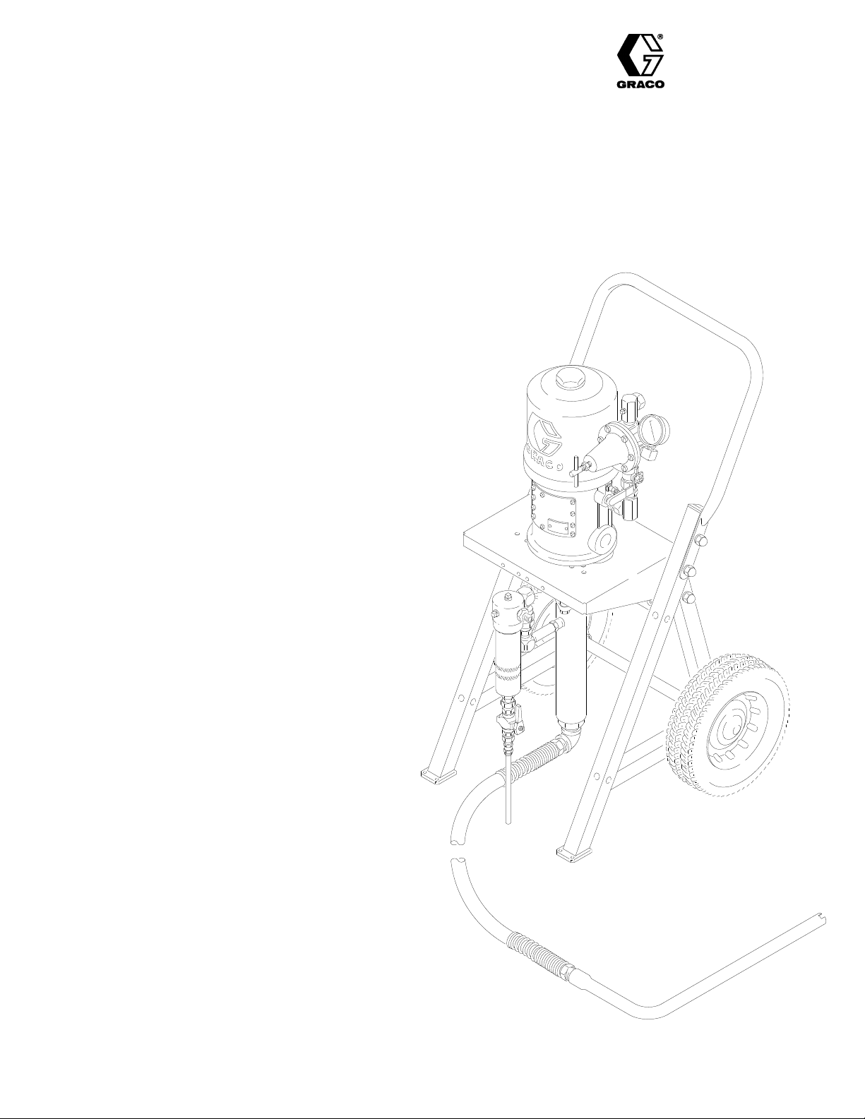
PORTABLE
30:1 Ratio President
Hydra-Spray Pumps
100
psi (7 bar) MAXIMUM AIR INLET PRESSURE
3000 psi (210 bar) MAXIMUM FLUID WORKING PRESSURE
Model 224-625, Series A
For cold spray applications
Includes pump and portable cart
Model 231-163
For cold spray applications
Includes pump, portable cart, hose, gun and tip
Model 224-630, Series A
For heated spray applications
Includes pump, portable cart, V
heater mounting kit 222-262, and circulating kit 222-261
iscon
heater
,
307-928
Rev F
Supersedes E
Model 231-160
For heated spray applications
Includes pump, portable cart, V
heater mounting kit 222-262, circulating kit 222-261,
hose, gun and tip
T
ABLE OF CONTENTS
Warnings
Terms 3
Installation 4-11
Operation/Maintenance 12
Parts
How
Accessories 19
Technical
Warranty Back
Graco T
.
. . . . . . . . . . . . . . . . . . . . . . . . . . . . . . . .
. . . . . . . . . . . . . . . . . . . . . . . . . . . . . . . . . . . . . . .
. . . . . . . . . . . . . . . . . . . . . . . . . . . . . . .
Drawings and Lists
to Order Replacement Parts
. . . . . . . . . . . . . . . . . . . . . . . . . . . . . . .
Data
.
. . . . . . . . . . . . . . . . . . . .
.
. . . . . . . . . . . . . . . . . . . . . . . . .
oll-Free Phone Numbers
iscon
heater
. . . . . . . . . . . . . . . . . . . . .
. . . . . . . . . . . . . . . . .
.
. . . . . . . . .
.
. . . .
,
2, 3
14-18.
15, 17
Back Cover
Cover
Back Cover
MODEL
224-625 SHOWN
GRACO INC. P.O. BOX 1441 MINNEAPOLIS, MN 55440-1441
COPYRIGHT 1988, GRACO INC.
Page 2

SAFETY
HIGH
PRESSURE FLUID CAN CAUSE SERIOUS INJURY. FOR PROFESSIONAL USE ONL
OBSERVE
FLUID INJECTION HAZARD
General
This
equipment
gun,
leaks or ruptured components can inject fluid through your skin and
into
your body and
need
for amputation. Also, fluid injected or splashed into the eyes or on
the
skin can cause serious damage.
NEVER
point the spray gun at
put
hand or fingers over the spray tip. NEVER try to “blow back” paint; this
is
NOT an air spray system.
ALWA
YS have the tip guard in place on
ALL W
ARNINGS. Read And Understand All Instruction Manuals Before Operating Equipment.
Safety
generates very high fluid pressure. Spray from the spray
cause extremely serious bodily injury
anyone or at any part of the body
the spray gun when spraying.
, including the
. NEVER
W
ARNINGS
Diffuser
The
spray gun dif
when the tip is not installed. Check the dif
tion
the
Follow
tip.
firmly
gun.
diffuser
Tip
ALWAYS
tip
does
of
Pressure Relief Procedure
Aim the spray gun into a grounded metal pail, holding the spray gun
to the pail. Using the lowest possible pressure,
If the fluid emitted is not dif
immediately
Guard
have the tip guard in place on the spray gun while spraying. The
guard alerts you to the fluid injection hazard and
not prevent,
your body close to the spray tip.
Y.
fuser breaks up spray and reduces the risk of fluid injec
fused into an irregular
.
the risk of accidentally placing your fingers or any part
fuser operation regularly
, below
, then remove the spray
trigger the spray
stream, replace the
helps reduce,
.
but
ALWAYS
or
NEVER try to stop or deflect leaks with your hand or body
Be sure equipment safety devices are
use.
Medical
If
CARE AT
exactly
Spray
Be
use.
malfunction
Safety
Whenever
gun
operative.
of
Trigger
Never
helps prevent the gun from triggering accidentally if it is dropped or
bumped.
follow the
removing the spray tip or servicing any system equipment.
Alert––Airless Spray W
any fluid appears
ONCE. DO NOT TREA
what fluid was injected.
Note
to Physician:
to treat the injury surgically as soon as possible
portant
delay
treatment to research toxicity
coatings injected directly into the blood stream. Consultation with a
otic
plastic
surgeon or reconstructive hand surgeon may be advisable.
Pressure Relief Procedure
operating
ounds
to penetrate your skin, get
Injection in the skin
T AS A SIMPLE CUT
is a traumatic injury
. T
oxicity is a concern with some ex
, right, before
properly before each
EMERGENCY MEDICAL
cleaning
.
. T
ell the doctor
.
It is im
. Do
not
Gun Safety Devices
sure all spray gun safety devices are operating properly before each
Do not
remove or modify any part of the spray gun; this can cause a
and result in serious bodily injury
.
Latch
you stop spraying, even
safety latch in the
Failure to set the safety latch can result in accidental triggering
the spray gun.
closed or “safe” position, making the spray gun in
for a moment, always set the spray
Guard
operate the spray gun with the trigger guard removed. This guard
Spray T
Use
tip
ALWAYS
spray tip to clean it.
NEVER
lieved
-
-
-
ip Safety
extreme caution when cleaning or changing spray tips. If the
clogs
while spraying, engage the spray gun safety latch immediately
follow the
wipe of
and the spray gun safety latch is engaged.
Pressure
To
reduce the risk of serious bodily injury
splashing
always follow this procedure whenever you shut off the pump,
checking or servicing any part of the spray system, when in
when
cleaning or changing spray tips, and whenever you stop
stalling,
spraying.
1. Engage
2. Shut
for
at least 10 minutes to allow it and the heater to cool.
3.
Shut of
4. Close
tem).
5. Disengage
6. Hold a metal part of the spray gun firmly to the side of a
grounded
sure.
7. Engage
8. Open
tainer
9. Leave
If
you suspect that the spray tip or hose is
that
pressure has not been fully relieved after following the steps
above,
VER
end coupling and relieve pressure gradually, then loosen completely.
Now clear the tip or hose.
Pressure Relief
f build-up around the spray tip until pressure is fully re
Procedure
and then remove the
Relief Procedure
in the eyes or on the skin, or injury from moving parts,
the spray gun safety latch.
of
f the main power to the heater
f the air to the pump.
the bleed-type
the spray gun safety latch.
metal pail, and
the spray gun safety latch.
the
drain valve (supplied in your system), having a con
ready to catch the drainage.
the drain valve open until you are ready to spray
Y SLOWL
master air valve (supplied in your sys
trigger the spray gun to relieve pres
Y loosen the tip guard retaining nut or hose
, including fluid injection,
, if used. Circulate the
completely clogged, or
spray
fluid
again.
.
-
-
-
-
-
EQUIPMENT MISUSE HAZARD
General
Any misuse of the spray equipment or accessories, such as
overpressurizing,
ids, or using worn or damaged parts, can cause them to rupture and result
in
fluid injection, splashing in the eyes or on the skin, or other serious bod
ily
injury
NEVER
to
malfunction.
CHECK
aged
Always
ommended
307-928
Safety
modifying parts, using incompatible chemicals and flu
, or fire, explosion or property damage.
alter or modify any part of this equipment; doing so
all spray equipment regularly and repair or replace worn or dam
parts immediately
wear protective eyewear
by the fluid and solvent manufacturer
.
, gloves, clothing and
could cause it
respirator as rec
.
-
-
-
-
System
The
WORKING
PRESSURE.
Be
the maximum working pressure of the pump. DO NOT exceed the
mum
tem.
Fluid
BE
the
the
ture
Pressure
30:1 ratio President pump
PRESSURE at 100 psi (7 bar) MAXIMUM INCOMING AIR
NEVER exceed 100 psi (7 bar) air pressure to the pump.
sure that all spray equipment and
working pressure of any component or accessory used in the sys
can develop 3000 psi (210 bar) MAXIMUM
accessories are rated to withstand
maxi
Compatibility
SURE that all fluids and solvents used are chemically compatible with
wetted parts shown in the
separate component manuals. Always read the manufacturer’s litera
before using fluid or solvent in this pump.
TECHNICAL DATA on the back page or in
-
-
-
Page 3

HOSE SAFETY
High
pressure fluid
ops
a leak,
high
pressure spray emitted from it can cause a fluid injection injury or
other
serious bodily injury or property damage.
ALL FLUID HOSES MUST HAVE SPRING GUARDS ON BOTH
The spring guards help protect the hose from kinks or bends at or
ENDS!
close
to the coupling which can result in hose rupture.
TIGHTEN
fluid can dislodge a loose coupling or allow high pressure spray to be
from the coupling.
emitted
NEVER
use a damaged hose. Before each use, check the entire hose
cuts, leaks,
couplings.
NOT try to recouple high pressure hose or mend it with tape or any
DO
other
device.
fluid.
HANDLE
move
with the inner tube and cover of the hose. DO
to
AND ROUTE HOSES CAREFULLY. Do not pull on hoses to
equipment. Do not use fluids or solvents which are not compatible
temperatures above 180 F (82 C) or below –40 F (–40 C).
in the hoses can be very dangerous. If the hose devel
split or rupture due to any kind of wear
all fluid connections securely before each use. High pressure
abrasion,
If any of
bulging cover
these conditions exist, replace the hose immediately
A repaired hose cannot safely contain the high pressure
, or damage or movement of the hose
, damage or misuse, the
NOT
expose Graco hoses
for
FIRE OR EXPLOSION HAZARD
Static
electricity is created by the flow of fluid through the pump and hose.
If
every part of the
may
occur
occur
when plugging in or unplugging a
ignite
fumes from solvents and the fluid being sprayed,
other
flammable substances, whether you are spraying indoors or out
and can cause a fire or explosion and serious bodily injury and
doors,
property
damage. Do
spray
area when there is any chance of igniting fumes still in the air
If
you experience any static sparking or even a slight shock while using
this
equipment, STOP SPRA
for proper grounding. Do not use the system again until the problem
tem
has
been identified and corrected.
spray equipment is not properly grounded, sparking
, and the system may
not plug in or unplug any power supply cords in the
become hazardous. Sparking may also
power supply cord. Sparks can
YING IMMEDIA
TELY.
Check the entire sys
dust particles and
.
-
Hose Grounding Continuity
Proper
hose grounding continuity is essential to maintaining a grounded
spray
system. Check the electrical resistance of your air and fluid hoses
at
least once a week. If your hose does not have a tag on it which speci
fies the maximum electrical resistance, contact the hose supplier or
manufacturer
in
the appropriate range for your hose to check the resistance. If the
tance
grounded
Also,
MOVING PARTS HAZARD
.
The
piston in the air motor
when
your
fingers or other body parts. Therefore, NEVER operate the pump
with
the air motor plates removed. KEEP CLEAR of moving parts when
starting
any
system component, follow the
2,
to prevent the pump from starting accidentally
10.
-
-
To ground the pump:
To ground the pump, loosen the grounding lug locknut (W) and
washer
wire
Fig
1. Refer to
other
for the maximum resistance limits. Use a resistance meter
exceeds the
or poorly
read
air is supplied to the motor
or operating the pump.
T
o maintain grounding continuity when flushing
,
sure
grounded
(X). Insert one end of a 1.5 mm (12 ga) minimum ground
(Y) into the slot in lug (Z) and tighten the locknut securely
end of the ground wire to a true earth ground.
recommended limits, replace it immediately
grounded hose can make your system hazardous.
FIRE OR EXPLOSION HAZARD
, located behind the air motor plates, moves
. Moving parts can pinch or amputate
Before checking or servicing the pump or
Pressure Relief
always hold a metal part of the spray gun firmly to the side of a
metal
pail, then trigger the spray gun.
page 19 to order a ground wire and clamp. Connect the
, below
Procedure
.
.
or relieving pres
X
resis
. An un
on page
. See
-
-
-
-
Grounding
To reduce the risk of static sparking, ground the pump, object being
sprayed,
CHECK
your
equipment:
1.
2.
3.
4.
5.
6.
7.
8.
9.
and all other spray equipment used or located in the spray area.
your local electrical code for detailed grounding instructions for
area and type of equipment. BE SURE to ground all of this spray
Pump:
use a ground wire and clamp as shown in Fig 1.
Air hoses:
Fluid hoses:
Heater (if used):
Air compressor:
Spray
grounded
Fluid supply container:
Object being sprayed:
All
only
face.
per
use only grounded air hoses.
use only grounded fluid hoses.
refer to the V
follow manufacturer’s recommendations.
gun:
grounding is obtained through connection to a properly
fluid hose and pump.
solvent pails used when flushing,
metal pails, which are conductive, placed on a grounded sur
Do not place the pail on a nonconductive surface, such as pa
or cardboard, which interrupts the grounding continuity
iscon
Heater manual, 307–805.
according to your local code.
according to your local code.
according to local code. Use
.
Fig
W
1
Z
Flushing Safety
Before
flushing, be sure the
grounded.
Procedure on page 2, and remove the spray tip from the spray gun.
-
Always use the lowest possible fluid pressure, and maintain firm
-
metal-to-metal
to
Refer to
contact between the spray gun and the pail during
reduce the risk of fluid injection injury
entire system and flushing pails are properly
Grounding
, at the left. Follow the
, static
sparking and splashing.
Y
Pressure Relief
IMPORTANT
United
States Government safety standards have been adopted under the Occupational Safety and Health Act. These standards – particularly the Gen
Standards, Part 1910, and the Construction Standards, Part 1926 – should be consulted.
eral
0864
flushing
-
TERMS
WARNING Alerts user to avoid or correct conditions that could
CAUTION Alerts user to avoid or correct conditions that could
cause
bodily harm.
damage to or destruction of equipment.
cause
NOTE
Identifies essential procedures or helpful information.
3307-928
Page 4

KEY
TYPICAL INSTALLATION
A Air
B
C
D
E
F Bleed-T
Y
10
21
22
28
29
32
33 Pump
45 Bleed-T
Model
Line Filter
Main Air Line
Air Line Lubricator
Fluid Hose
Spray Gun
Ground Wire (required)
Drain V
Suction T
Filter Outlet Nipple
Air Regulator
Suction Hose
Fluid Filter
(required)
224-625 Shown
ype Master Air V
alve (required)
ube
ype Master Air V
21
alve
alve
33
29 32
A
F
B
Y
28
45
C
22
E
10
D
0865
4 307-928
Page 5

INSTALLATION
Be
sure that all operators read and understand this entire
manual
nents
Reference numbers and letters in parentheses refer to
the Typical Installation drawing, Figs. 1-5, and the parts
drawings and lists on pages 13-18.
Accessories mentioned are available from your Graco
distributor
sories, be sure they are adequately sized to meet your
system’s
The Typical Installation above is only an example. For as
sistance in designing a system to meet your particular
needs, contact your Graco representative or Graco
Technical
SYSTEM ACCESSORIES
Install an air line filter (A) in the main air line (B), to remove
supply. To provide automatic lubrication of the air motor
install an air line lubricator (C) downstream from the
bleed-type master air valve (45). Install a second bleed
valve
servicing.
and the separate manuals supplied with compo
and accessories before using this equipment.
(see page 19). If you supply your own acces
requirements.
Assistance (see back page).
harmful dirt and moisture from the compressed air
(F) in the main
air line, to isolate the accessories for
WARNING
-
-
-
,
AND GUN CONNECTIONS
HOSE
Refer to the Typical Installation drawing on page 4. Assemble
pump
Connect one end of the fluid hose (D) to the filter outlet
nipple
DO
ond
Close the bleed-type master air valve (45) and the air
regulator (28). Connect the main air line (B) to the 1/2
npt(f)
the suction hose (29) and suction tube
fluid intake.
(22) and the
NOT install the spray tip in the gun yet. T
gun with the sprayer
air regulator inlet.
other to the fluid inlet of the gun (E).
, refer to pages 10 and 1
(21) to the
o use a sec
1.
GROUNDING
WARNING
Before operating the pump, ground the system as
explained under FIRE OR EXPLOSION HAZARD
Grounding
and
on page 3.
-
The
bleed-type master air valve (45) and the fluid
drain valve (10) are supplied with your pump, to
reduce the risk of serious bodily injury includ
help
ing fluid injection, splashing in the eyes or on the
skin,
or injury from moving parts if
ing
or repairing the pump.
The
bleed-type master air valve
trapped
air
cycle unexpectedly. The valve is located down-
stream
The
sure in the displacement pump, hose, and gun;
triggering the gun to relieve pressure may not be
sufficient.
between this valve
is shut of
fluid drain valve
f. T
rapped air can cause the pump to
from the air regulator
and the pump after the
assists in
you are adjust
relieves air
.
relieving fluid pres
-
-
-
5307-928
Page 6

Model
224-625 Shown
33
17
32
ARROW ON
30
BODY MUST
POINT UP
17 39
4
29
21
Fig. 2
6 307-928
0866
Page 7

CONVERTING
ING
SYSTEM
To
convert pump Models 224-625 or 231-163 to a heated
circulating
Viscon
Heater Mounting Kit 222-262
Circulating Kit 222-261
Hose Kit 222-263
THE PUMP T
O A HEA
unit, order the following:
Fluid Heater
, Model 220-522
TED CIRCULA
WARNING
The Viscon Heater must be installed by a quali-
fied
electrician in compliance with all state and lo
cal codes and regulations, to reduce the risk of
electric
installation
shock or other serious bodily injury during
or operation.
The heater requires a 120 VAC, single-phase,
16.7 Amp power supply. Refer to the Viscon
Heater
DO
containing
fire
Manual, 307-805, for further information.
NOT
plug or unplug the power cord in any area
flammable materials or fumes, to
avoid
or explosion resulting in serious bodily injury
T-
NOTE: Reference
example,
Apply 110-1
numbers
marked with an asterisk (for
61*) are included in kit 222-262.
10 pipe sealant (included in the kit) to
all male threads, except at swiveling connections.
1. Remove
back
the cover from the electrical box (G) at the
of the heater
. Screw the bushing (66*) into the
inlet of the electrical box. Install the cord grip elbow
(67*)
in the bushing. See Fig. 3.
2. Thread the cord (68*) through the elbow (67*) and
into the electrical box. Attach the black lead to the
leftmost
nal,
and the
terminal, the white lead to the center
green ground wire to the rightmost termi
termi
-
-
nal. Tighten all terminal nuts to 30 in-lb (3.4 N.m).
-
Tighten
the
the nut on the cord grip elbow (67*) to secure
cord. See Fig. 3.
WARNING
The electrical cord (68*) is rated for 105C
(221F). Do not substitute a lower temperature
rated,
generally available cord.
NOTE: Mount
.
the heater (58) on the
follows. T
wo people are required to perform this
operation.
back of the cart as
Installing Heater Mounting Kit 222-262
WARNING
Before installing the heater, heater mounting kit
and
circulating kit, follow the
cedure
on page 2. Disconnect all hoses from the
Pressure Relief Pro
pump.
G
66*
67*
3. Align the heater (58) mounting posts with the four
at the back of the cart’
holes
(H).
See Fig. 4. Secure the heater to the bracket with
the M8 x 1.25 screws and lockwashers
the
heater
Remove the fluid filter (32) from the pump (33). Re
4.
-
move and discard the two elbows (17), check valve
(30),
outlet.
.
and long 3/8 npt nipple (39) from the pump fluid
See Fig. 2.
s pump support bracket
supplied
with
-
Refer to page 8 to continue the procedure.
WHITEBLACK
Fig. 3
68*
TIGHTEN TERMINAL NUTS
T
O 30 in-lb (3.4 N.m)
GREEN (GROUND)
0867
7307-928
Page 8

5. Screw
6. Install the 3/8 npt nipple (61*) in the heater outlet.
7.
Installing Circulating Kit 222-261
Before installing the heater, heater mounting kit
and
cedure
pump.
the check valve (62*) into the pump’
let,
making certain
points away from the pump. Screw the rigid end of
the
adapter (63*) onto the check valve. See Fig. 4.
Screw the male end of the 90 swivel (23*) into the
inlet of the fluid filter (32). Screw the female end of
the swivel (23*) onto the nipple (61*) at the heater
outlet, and tighten securely. When properly assembled,
the
Screw the elbow (64*) into the heater’s inlet.
the 1/2” x 3’ (0.9 m) hose (65*) to the elbow.
the
(63*)
the filter’s outlet
back of the cart.
other end of the hose to the swivel of the adapter
at the pump outlet.
circulating kit, follow the
on page 2. Disconnect all hoses from the
that the arrow on the check valve
nipple (22) will face toward
WARNING
Pressure Relief Pro
s fluid out
Attach
Attach
-
-
mounting
bracket (H), working from the inside. Place another
insulator
of the bracket. Use the screws to attach the back
pressure
et.
4. Screw one of the nipples (22) into the outlet in the
base of the back pressure regulator (76), then
screw
male
elbow
tor,
5. Screw
fluid
elbow faces left. Install the CIRC end of the threeway
is
at the front.
6. Screw a second elbow (44) onto the IN branch of
the three-way valve (70), so the elbow points upward. Connect one end of the hose (72) to the elbow,
let
of the back pressure regulator
holes on the left side of the pump support
(74) on each of
regulator (76) to the pump support
one of the elbows (44) onto the nipple so the
end of the elbow faces forward. Install another
(44) in the inlet of the back pressure
then install another nipple (22) in the elbow
an elbow (44) into the open port of the pump
intake manifold (69), so the female end of the
ball valve (70) in the elbow
and the other end to the nipple (22) at the out
the screws on the outside
, so the valve handle
.
brack
regula
.
-
-
-
NOTE: Reference numbers marked with a symbol (for
example,
Apply 110-1
all male threads, except at swiveling connections.
1. Unscrew
elbow
(4) and set the hose aside. Remove the elbow
(4)
from the pump intake and discard. See Fig. 2.
2. Screw the rigid end of the manifold (69) onto the
intake, and attach the suction hose (29) to the
pump
swivel
end of the manifold. See Fig. 4.
3. Place
a washer
the screws (75). Insert the screws through the
69), are included in kit 222-261.
10 pipe sealant (included in the kit) to
the suction hose (29) from the pump intake
(73) and insulator (74) on each of
7. Connect the drain hose (71) to the DRAIN end of
the
three-way valve (70
8. Connect
inlet
of the back pressure regulator
9. Connect
on
page 5.
the fluid return line to the nipple (22) at the
the air and fluid hoses and
).
.
gun as explained
GROUNDING
WARNING
Before operating the pump, ground the system as
explained under FIRE OR EXPLOSION HAZARD
Grounding
and
on page 3.
8 307-928
Page 9

76
44
22
72
(REF)
74
73
75
33
*62
ARROW ON BODY
MUST POINT A
FROM PUMP
44
B
WAY
*63
7
A
H
*65
(REF)
B
72
71
*68
*67
PART
ITEM 58
OF
69
44
70
66*
29
*23
21
–
22
*61
32
58
64*
H
65*
Fig. 4
A
0868A
9307-928
Page 10

CONVERTING T
To
convert your sprayer to a
following
parts
Models 224-625 and 231-163 (Refer to Fig 5 and the
Parts
NOTE: For Model 224–625, order all of the following
P
ART NO.
162-453
208-663
204-940
210-540
1. Remove
2. Screw the first fluid hose (D) onto a swivel (L), then
3. Screw
applicable paragraph for your model. Order the
listed, and perform the assembly procedure.
Drawing on page 14)
performing this procedure, follow the
Before
sure
Relief Procedure
hoses
from the pump.
parts.
swivel and fluid hose, order only one of each
the following parts.
the
fluid filter (32). Install a 162-453 Nipple (K) in its
place. See Detail A of Fig 5.
screw the swivel onto the fluid inlet of the gun (E).
See
Detail B of Fig
and gun.
el
fluid
filter (32). Screw the second hose onto the
outlet
nipple (K) of the fluid filter
O A TWO-GUN SYSTEM
two-gun system, refer to the
WARNING
Pres-
on page 2. Disconnect
For Model 231-163, which includes a gun,
DESCRIPTION QTY
NIPPLE; 1/4 npt x 1/4 npsm
GUN, airless spray
SWIVEL, straight; 1/4 npt(m) x
1/4 npsm(f) 2
HOSE, fluid; nylon;
1/4” (6 mm) I.D.; 1/4 npsm(fbe);
25 ft (7.6 m) long
the plug (16) from the optional outlet port of
5. Repeat for the other hose, swiv
the first hose onto one outlet nipple (22) of the
. See Detail A.
all
of
other
Model 224-630 and 231-160 (Refer to Fig 5 and the
Parts
Drawing on page 16)
WARNING
performing this procedure, follow the
Before
sure
Relief Procedure
hoses
from the pump.
NOTE: For Model 224-630, order all of the following
parts.
For Model 231-160, which includes a gun
and
hose kit, order two 162-453 nipples and only
one
of each of the other parts.
P
ART NO.
162-453
100-840 ELBOW
208-327
222-263
1
2
1. Remove
the
fluid filter (32). Install a 162-453 Nipple (K) in its
place. See Detail A of Fig 5.
2.
2
-
Install the 100-840 Elbow (M) in the optional inlet of
the back pressure regulator (76). Screw a 162-453
Nipple
3. Screw the first insulated fluid hose kit (N) onto the
fluid
inlet of the gun
and
gun. See Detail D.
4. Connect
the outlet nipple (22) of the fluid filter (32). Connect
the
fluid supply line of the second hose kit to the other
outlet
return
and
K) of the back pressure regulator (76). See
C.
tail
DESCRIPTION QTY
NIPPLE; 1/4 npt x 1/4 npsm
1/4 npt (m x f)
GUN, airless spray
HOSE KIT
1/4” ID; cpld 1/4 npsm (fbe);
25 ft (7.6 m) long
the plug (16) from the optional outlet port of
(K) into the elbow (M). See Detail C of Fig 5.
the fluid supply line of the first hose kit (N) to
nipple (K). See Detail A. Similarly
lines of the hose kits (N) to the inlet nipples (22
on page 2. Disconnect
, street, 90
, fluid, insulated; nylon;
(E). Repeat for the other hose kit
;
Pres-
all
, connect the
De
2
1
2
2
-
10 307-928
Page 11

DETAIL
A: HOSE CONNECTIONS A
FLUID FIL
TER (ALL MODELS)
32
T
DET
AIL B: ASSEMBL
(MODELS 224–625 AND 231–163)
Y OF HOSE AND GUN
E
L
D
22
(TO
FIRST
GUN)
DET
AIL C: FLUID RETURN CONNECTIONS A
BACK PRESSURE VALVE (MODELS 224-630 AND 231-160 ONL
4422
(FROM
FIRST
GUN)
K
(TO
SECOND
GUN)
0869
T
76
K
(FROM
SECOND GUN)
M
22
44
72
(TO
3–WAY
VALVE)
0870
Y)
0871A
Fig 5
DET
AIL D: ASSEMBL
FLUID RETURN LINE
Y OF HOSE KIT AND GUN (MODELS 224-630 AND 231-160)
EN
FLUID SUPPL
Y LINE
0872
11307-928
Page 12

OPERATION-MAINTENANCE
WARNING
Pressure
To
reduce the risk of serious bodily injury
fluid
injury from moving parts, always follow this procedure
ing
installing, cleaning or changing spray tips, and
whenever
1.
2. Shut off the main power to the heater, if used.
3.
4. Close the bleed-type master air valve (supplied
5.
6. Hold a metal part of the spray gun firmly to the
7.
8. Open
9. Leave
If you suspect that the spray tip or hose is com-
pletely
relieved after following the steps above, VERY
SLOWLY
end coupling and relieve pressure gradually, then
loosen
For your safety, before operating the equipment
be sure all operators have read and fully understand
this manual and all manuals supplied with each
component
Relief Procedure
, including
injection, splashing in the eyes or on
whenever you shut of
or servicing any part of the spray system, when
you stop spraying.
Engage the spray gun safety latch.
Circulate
it
and the heater to cool.
Shut of
in your system).
Disengage the spray gun safety latch.
side of a grounded metal pail, and trigger the
spray
Engage the spray gun safety latch.
having
spray
the fluid for at least 10 minutes to allow
f the air to the pump.
gun to relieve pressure.
the drain valve (supplied in your system),
a container ready to catch the drainage.
the drain valve open until you are ready to
again.
clogged, or that pressure has not been fully
loosen the tip guard retaining
completely
all the
. Now clear the tip or hose.
warnings, cautions and instructions in
or accessory.
f the pump, when check
WARNING
the skin, or
nut or hose
valve.
Hold a metal part of the spray gun firmly to the side
of a grounded metal pail and trigger the gun. Slowly
the
air regulator until the pump
cycle
slowly until all the air is pushed out of the fluid lines.
Release
-
pump
With the pump and lines primed, and with adequate air
pressure and volume supplied, the pump will start and
stop
Follow
then
Use
pressure. Always use the lowest pressure necessary to
achieve
and cause premature wear of the pump packings and
spray
Keep the wet-cup filled with Graco Throat Seal Liquid
(TSL) to help prolong the packing life. Check the tightness of the packing nut weekly. The packing nut should
be tight enough to prevent leakage – no tighter. Always
follow the Pressure Relief Procedure Warning at left
before
Never allow the pump to run dry of the fluid being
pumped. A dry pump will quickly accelerate to a high
speed, possibly damaging itself. If your pump accelerates
check the fluid supply. If the supply container is empty
and air has been pumped into the lines, refill the supply
container
sure
pump
Heated Systems
Operating instructions for a heated circulating system
are provided in the Viscon Heater manual, 307-805.
Read
heater
the gun trigger and engage the safety latch;
will stall against the pressure.
as the spray gun is triggered and released.
the
Pressure Relief Procedure W
install the spray tip in the gun.
the air regulator to control
the desired
tip.
adjusting the packing nut.
quickly
to eliminate all air
, or is running too fast, stop it immediately and
and prime the pump and lines with fluid, being
as described in “Shutdown and Care,” below
and understand all warnings and instructions in
manual before operating a heated system.
results. Higher pressures waste fluid
from the fluid system, or flush the
starts. Allow the pump to
arning
the pump speed and fluid
open
the
at left,
.
the
Flush the Pump Before Using
Pumps are tested with lightweight oil which is left in to
protect
fluid,
ing
Starting and Adjusting the Pump
Be
are
Place
valve (10) for priming. Open the bleed-type master air
12 307-928
the pump parts. T
flush the
it.
pump with a compatible solvent before us
Before flushing,
flushing pails are properly grounded. Refer to
Grounding on page 3. Follow the Pressure Relief Procedure Warning above, and
spray
tip from the gun.
sible fluid pressure, and maintain firm metal-tometal
contact between the gun and the pail during
flushing to reduce the risk of fluid injection, static
sparking,
sure the air regulator and bleed-type
closed.
the suction tube (21) in the fluid pail. Open the drain
and
splashing in the eyes or on the skin.
DO NOT INST
o prevent contamination of the
WARNING
be sure the entire system and
remove the
Always use the lowest pos
master air valve
ALL THE SPRA
Y TIP YET!
-
In
circulating systems, adjust the back pressure regulator
(76)
and pump air pressure regulator (28) to obtain prop
er
spray pressure at the gun and maintain suf
flow to prevent fluid settling.
lation
The
three-way ball valve (70) selects either fluid
or draining. To circulate fluid back to the pump, turn
tion
the handle toward the CIRC end of the valve. To drain
fluid,
turn the handle toward the DRAIN end.
Shutdown and Care
Always
at
the bottom of its stroke to keep fluid from drying on the
exposed displacement rod and damaging throat packings.
Always
the
of
first with water and then with mineral spirits. If you are
pumping
Relieve pressure and leave the mineral spirits in the
pump
follow the
left, whenever you shut
flush
fluid can dry on the displacement rod, and at the end
each day
oil-based fluids, flush with mineral spirits only
to prevent corrosion.
Pressure
the pump with a compatible solvent before
. If you are pumping water-based fluid,
Relief Procedure W
of
f the pump. Stop the pump at
ficient circu
circula
arning
flush
-
-
-
.
Page 13

PARTS
ARTS LISTS
P
DRA
AND
WINGS
13307-928
Page 14
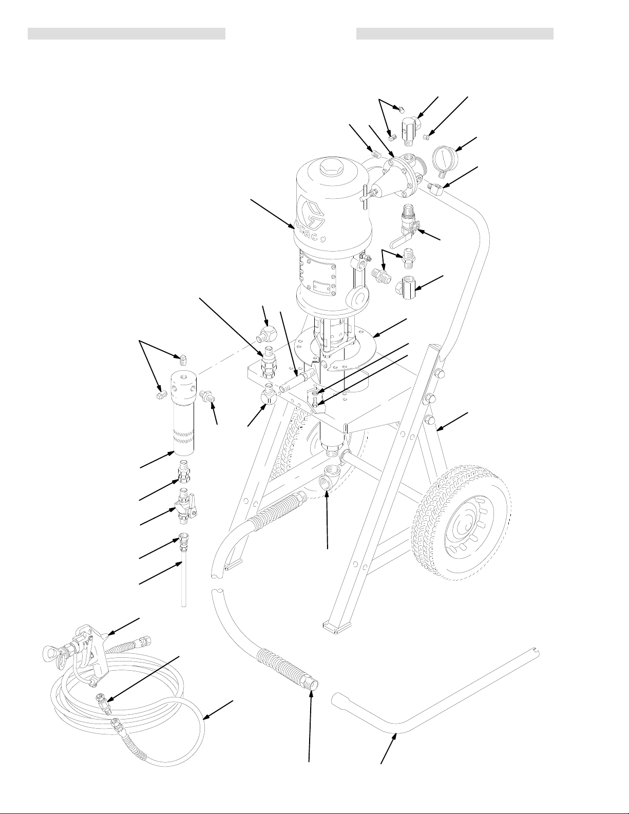
Model
224–625,
Includes items 1–56
Model 231–163
Includes items 1–79
Series A
PARTS
33
DRA
WING
16
28
5
20
5
6
15
16
32
54
10
ARROW ON
30
BODY MUST
POINT UP
22
17
17
39
37
45
18
47
1
3
7
14 307-928
55
56
77
79
78
29
4
21
0873A
Page 15

Model
224–625, Series A
Includes items 1–56
Model 231–163
Includes items 1–79
PARTS LIST
REF
NO. P
ART NO.
1 100–016 LOCKW
DESCRIPTION
ASHER, spring; 1/4”
3 100–270 CAPSCREW
1/4–20 x 5/8” long
4 100–349 ELBOW
5 100–403
6 101–180
PLUG, pipe, sq hd; 1/8 npt
GAUGE, air pressure;
, 90; 3/4 npt(fbe)
0–200 psi (0–14 bar)
7 224–044 CART
, portable
See 308–136 for parts
10 210–658
BALL VALVE; 3/8 npt(mbe)
See 306–861 for parts
15 187–357 ELBOW
, street, 90;
1/4 npt (m x f)
16 100–509
17 155–699 ELBOW
18 157–416
PLUG, pipe, sq hd; 1/4 npt
, 90; 3/8 npt (m x f)
UNION, 90; 1/2 npt(f) x
1/2 npsm(f) swivel
20 162–376
MANIFOLD; 1/2 npt (m x f)
90
swivel; 3 holes (1/8 npt)
in body
21 165–767
SUCTION TUBE; 3/8 npt;
18” (457 mm) long 1
22 162–453
28 206–197
NIPPLE; 1/4 npt x 1/4 npsm
AIR REGULA
1/2 npt(f) inlet and outlet;
0–125 psi (0–9 bar) range
29 214–960
HOSE, suction; 3/4” ID; nylon;
coupled 3/4 npt (mbe);
3.5’ (1 m) long, w/spring guard
, hex hd;
TOR
QTY
REF
2
NO. P
ART NO.
30 206–831
DESCRIPTION
CHECK V
See 306–861 for parts
2
31 206–994 THROA
1
3
32 218–029
1 pint (0.5 liter); not shown
FLUID FIL
See 307–273 for parts
1
33 223–586
30:1 PRESIDENT PUMP
See 306–981 for parts
1
37 158–491
39 160–790
1
45 107–142 VAL
NIPPLE; 1/2 npt
NIPPLE; 3/8 npt
1/2 npt (m x f)
1
3
2
1
47 188–595
54 155–665
55 205–448
56 185–973
MOUNTING BRACKET
UNION, adapter; 3/8 npt(m) x
3/8 npsm(f) swivel
COUPLING, hose; 3/8 npsm(f)
HOSE, nylon; 1/4” (6 mm) ID;
28” (71
77 208–663 HYDRA–SPRA
1
78 223–540
See 307–046 for parts
HOSE, fluid; nylon;
1/4” (6 mm) ID;
1
coupled 1/4 npsm (fbe);
25’ (7.6 m) long
79 204–940 SWIVEL
1
See 306–861 for parts
1
ALVE
T SEAL LIQUID;
TER
VE, air
, bleed–type;
1 mm) long
Y GUN
, pump
QTY
1
1
1
1
2
1
1
1
1
1
1
1
1
1
HOW T
1 To be sure you receive the correct replacement parts, kits or
accessories, always give all of the information requested in the
chart
below
2.
Check
the
3.
Order all parts from your nearest Graco distributor
6 digit
Part Number
.
the parts list
ref. no. when ordering.
O ORDER P
to identify the correct part number; do not use
Qty
Part Description
ARTS
.
15307-928
Page 16

Model
224–630, Series A
Includes items 1–76
Model 231–160
Includes items 1–85
*67
*68
66*
PARTS
*61
58
32
DRA
23*
WING
16
22
28
16
5
20
5
6
7
(REF)
PART
OF
ITEM 58
*64
*65
REF
. NO. 78 HOSE KIT
INCLUDES ITEMS 79–85
A
22
*65
*62
ARROW ON BODY
MUST POINT A
FROM PUMP
WAY
72
71
57
10
76
44
A
*63
74
33
73
44
75
37
47
15
45
37
18
1
3
7
69
79
16 307-928
77
85
81
84
70
44
83
82
80
21
29
0875B
Page 17

Model
224–630, Series A
Includes items 1–76
Model 231–160
Includes items 1–85
PARTS LIST
REF
NO. P
ART NO.
1 100–016 LOCKW
DESCRIPTION
ASHER, spring; 1/4”
3 100–270 CAPSCREW
1/4–20 x 5/8” long
5 100–403
6 101–180
PLUG, pipe, sq hd; 1/8 npt
GAUGE, pressure, air;
0–200 psi (0–14 bar)
7 224–044 CART
, portable
See 308–136 for parts
10 210–658
DRAIN VALVE; 3/8 npt(mbe)
See 306–861 for parts
15 187–357 ELBOW
, street, 90_;
1/4 npt (m x f)
16 100–509
18 157–416
PLUG, pipe, sq hd; 1/4 npt
UNION, 90_; 1/2 npt(f) x
1/2 npsm(f) swivel
20 162–376
MANIFOLD; 1/2 npt (m x f)
90_
swivel; 3 holes (1/8 npt)
in body
21 165–767
SUCTION TUBE; 3/8 npt;
18” (457 mm) long 1
22 162–453[
23 155–494*
NIPPLE; 1/4 npt x 1/4 npsm
ADAPTER, union, 90
3/8 npt(m) x 3/8 npt(f) swivel
28 206–197
AIR REGULA
1/2 npt(f) inlet and outlet;
0–125 psi (0–9 bar) range
29 214–960
HOSE, suction; 3/4” ID; nylon;
coupled 3/4 npt (mbe);
3.5’ (1 m) long, w/spring guard
31 206–994 THROA
T SEAL LIQUID;
1 pint (0.5 liter); not shown
32 218–029
FLUID FIL
TER
See 307–273 for parts
33 223–586
30:1 PRESIDENT PUMP
See 306–981 for parts
37 158–491
44 100–840[ ELBOW
NIPPLE; 1/2 npt
, street, 90_;
1/4 npt (m x f)
VE, air
45 107–142 VAL
, bleed–type;
1/2 npt (m x f)
47 188–595
57 150–286
58 220–522 VISCON@
MOUNTING BRACKET
ADAPTER; 3/8 npt (m x f)
HEA
See 307–805 for parts
61 156–849*
62 206–962*
63 159–801*
NIPPLE; 3/8 npt
CHECK VALVE; 3/8 npt (mbe)
UNION, adapter
3/8 npt(f) x 1/2 npsm(f) swivel
64 158–683* ELBOW
65 235–022*
HOSE, fluid; nylon; 1/2” ID;
, 90_; 1/2 npt (m x f)
cpld 1/2 npt (mbe);
3’ (0.9 m) long
66 107–219*
BUSHING; 3/4 npt(m) x
1/2 npt(f) 1
67 102–363* ELBOW
, cord grip, 90
1/2 npt (m); includes nut,
68 110–160*
washer
CORD ASSY
600V
, and grommet
; 20 AMP; 105_C (221
6.5 ft (2 m) long
69 166–998[
MANIFOLD, inlet; 1/4 npt(f) x
3/4 npt(f) x 3/4 npsm(f) swivel
, hex hd;
_;
TOR
, pump
TER (120V)
, 90
_;
_;
, heater; 12 A
WG;
_F);
QTY
REF
NO. P
70 214–711[
2
ART NO.
2
71 206–965[
3
72 206–966[
1
1
73 100–527[ W
74 167–002[ INSULAT
1
75 102–254[ SCREW
1
76 206–819[ REGULAT
3
77 208–327
1
78 222–263
1
79 223–759 .
3
80 169–797 .
81 169–795 .
1
82 100–139 .
83 159–840 .
1
84 214–701 .
1
85 210–500 . FIL
1
1
*
1
2
4
Included in Heater Mounting Kit 222–262. See page
18.
[
Included in Circulating Kit 222–261. See page 18.
1
1
1
1
1
1
1
1
1 To be sure you receive the correct replacement parts, kits or
accessories, always give all of the information requested in the
chart
below
2.
Check
the
3.
Order all parts from your nearest Graco distributor
6 digit
Part Number
.
the parts list
ref. no. when ordering.
1
1
1
1
DESCRIPTION
BALL VALVE, three–way;
1/4 npt(m)
See 306–861 for parts
HOSE, drain; nylon; 1/4” ID;
cpld 1/4 npsm(f)
HOSE; PTFE;r1/4” ID;
cpld 1/4 npsm (fbe) swivel;
18” (457 mm) long 1
ASHER, wrought; 1/4”
OR, heat
, hex hd; 1/4–20 x
7/8” (19 mm) long 2
OR, back pressure
See 306–860 for parts
GUN, airless spray
See 307–046 for parts
HOSE KIT
Includes items 79–85
HOSE, fluid, insulated; nylon;
1/4” ID; cpld 1/4 npsm (fbe)
swivel; 25 ft (7.6 m) long
NIPPLE; 1/4 npsm x 1/8 npt
MANIFOLD; 1/8 npt(f)
PLUG, hex socket; 1/8 npt
ADAPTER; 1/8 npt(m) x
1/4 npt(f) 1
HOSE, fluid; nylon; 3/16” ID;
cpld 1/4 npt(m) x 1/4 npsm(f)
swivel; 3 ft (0.9 m) long
TER, fluid, in–line;
100 mesh; 1/4 npsm(m) x
1/4 npsm(f) swivel
HOW T
O ORDER P
to identify the correct part number; do not use
Qty
Part Description
ARTS
.
QTY
1
1
2
4
1
1
1
1
2
1
1
1
1
17307-928
Page 18

HEATER MOUNTING KIT 222–262
CIRCULATING KIT 222–261
Required to convert Models 224–625 and 231–163 to
heated
Includes 6 ml supply of sst pipe sealant 1
units. Consists of:
Ref. No.
23 1 65 1
61 1 66 1
62 1 67 1
63 1 68 1
64 1
Qty
Ref. No.
MANUAL
Listed below by the assembly
parts.
Assembly Ref
Changed Status No.
All Models
Qty
10–110.
CHANGE SUMMAR
ADDED 47 188–595 Bracket
Required
culating
Includes 6 ml supply of sst pipe sealant 1
to convert Models 224–625 and 231–163 to cir
units. Consists of:
Ref. No.
22 2 72 1
44 4 73 2
69 1 74 4
70 1 75 2
71 1 76 1
Qty
Ref. No.
10–110.
Y
changed are ADDED
Part No.
Name
-
Qty
18 307-928
Page 19

ACCESSORIES
USE GENUINE GRACO PARTS AND ACCESSORIES
Must
be purchased separately
GROUNDING CLAMP 103–538
GROUND WIRE 208–950
25 ft (7.6 m) long, 12 gauge (1.5 mm
AIR LINE LUBRICA
TOR
250 psi (17.5 bar) MAXIMUM WORKING PRESSURE
214–848
214–849
1/2 npt inlet and outlet
3/4 npt inlet and outlet
.
)
GROUNDED NYLON FLUID HOSE
3000 psi (210 bar) MAXIMUM WORKING PRESSURE
Part
No.
214–700
214–701
210–540
210–541
214–703
214–705
214–920
ID Length
3/16” (4.8 mm)
3/16” (4.8 mm)
1/4” (6.4 mm)
1/4” (6.4 mm)
3/8” (9.5 mm)
3/8” (9.5 mm)
3/8” (9.5 mm)
2 ft (610 mm)
(fbe) swivel
3 ft (914 mm)
25 ft (7.6 m)
50 ft (15.2 m)
(fbe) swivel
25 ft (7.6 m)
50 ft (15.2 m)
100 ft (30.4 m)
Thd. Size
1/4 npsm
1/4 npt(m)
x 1/4
npsm(f)
swivel
1/4 npsm
(fbe) swivel
1/4 npsm
3/8 npt
(mbe)
3/8 npt
(mbe)
3/8 npt
(mbe)
AIR LINE FIL
TER
250 psi (17.5 bar) MAXIMUM WORKING PRESSURE
106–149
106–150
GROUNDED BUNA–N AIR SUPPL
1/2 npt inlet and outlet
3/4 npt inlet and outlet
Y HOSE
175 psi (12 bar) MAXIMUM WORKING PRESSURE
Part
No.
205–418
205–216
205–273
208–594
BACK
PRESSURE REGULATOR 206–819
ID Length
1/2” (13 mm)
1/2” (13 mm)
1/2” (13 mm)
1/2” (13 mm)
6 ft (1.8 m)
15 ft (4.5 m)
25 ft (7.6 m)
50 ft (15 m)
Thd. Size
1/2 npt(m)
1/2 npt(m)
1/2 npt(m)
1/2 npt(m)
3000 psi (210 bar) MAXIMUM WORKING PRESSURE
Use
in circulating system fluid return line to regulate back
pressure to gun and maintain proper circulating pressure.
FLUID
PRESSURE REGULATOR 206–661
3000 psi (210 bar) MAXIMUM WORKING PRESSURE
Use
at each gun drop in multiple gun systems, to regulate
fluid
pressure to each gun.
STAINLESS
STEEL AIRLESS SPRA
Y GUN
5000 psi (350 bar) MAXIMUM WORKING PRESSURE
208–327
208–663
208–664
220–954 .090”
VISCON
.037” orifice, 2–finger trigger
.090” orifice, 2–finger trigger
.090” orifice, 4–finger trigger
orifice, 2–finger trigger
Less
FLUID HEA
tip guard
TER 220–522
, RAC IV Drip
4000 psi (276 bar) MAXIMUM WORKING PRESSURE
Reduces fluid viscosity for easier spraying. 120 V, single–phase,
Manual
16.7 Amp. Stainless steel. Refer to
307–805.
Instruction
WARNING: Not for use in hazardous areas containing
flammable
INSULA
materials or fumes.
TED HOSE KIT 222–263
3000 psi (210 bar) MAXIMUM WORKING PRESSURE
25 ft. (7.6 m) nylon fluid hose for use with heated systems.
Includes in–line fluid filter
3
ft. (0.9 m) whip hose.
HEA
TER CONVERSION KITS
Use
to convert pump Models 224–625 and
, circulating manifold,
231–163 to a
and
heated circulating spray system. See pages 16–18 for
The V
iscon
parts.
Kit
222–263 are also required, and must be ordered sep
arately
(see above).
222–262
222–261
SST PIPE SEALANT 1
Heater 220–522 and Insulated Hose
Heater Mounting Kit
Circulating Kit
10–110
Apply to all non–swiveling pipe connections.
6 ml supply
.
19307-928
-
-
Page 20

TECHNICAL
PTFE
DA
TA
Maximum
Maximum
Ratio 30:1
Maximum
pump speed
working pressure
.
. . . . . . . . . . . . . . . . . . . . . . . . . . . . . . .
incoming air pressure
.
. . . . . . . . . . . . . . . . . . . . . . . . . . . . . .
3000 psi (210 bar)
100 psi (7 bar)
. . . . . . . . . . . . . . . . . . . . . . . . . . . . . . . . . . . . . . . . . . . . . . . . . . . . . . . . . . . . . . . .
recommended
.
. . . . . . . . . . . . . . . . . . . . . . . . . . . . . . .
60 cpm (1.0 gpm [3.8 liters/min])
at continuous operation
Air
consumption
.
. . . . . . . . . . . . . . . . . . . . . . . . . . . . . . . . . . . . . . . . . . .
(0.79 m
approx. 23 scfm
/min) at 1.0 gpm
(3.8 liter/min) flow rate at
70 psi (4.8 bar) air pressure
W
etted parts
is
a registered trademark
THE
.
. . . . . . . . . . . . . . . . . . . .
GRACO W
ARRANTY AND DISCLAIMERS
See separate component instruction manuals
WARRANTY
Graco
warrants all equipment manufactured by it and bearing its name to be free from defects in material and workman
ship on the date of sale by an authorized Graco distributor to the original purchaser
for
breach of this warranty
, Graco
will, for a period of twelve months from the date of sale, repair or replace any part of the
equipment proven defective. This warranty applies only when the equipment is
accordance with Graco’
This
warranty does not cover
misapplication, abrasion, corrosion, inadequate or improper maintenance, negligence, accident, tampering, or
lation,
substitution
of non–Graco component parts. Nor shall Graco be liable for malfunction, damage or wear caused by the
incompatibility with Graco equipment of
improper
als
design, manufacture, installation, operation or
not supplied by Graco.
s written recommendations.
, and Graco shall not be liable for
structures, accessories, equipment or materials not supplied by Graco, or the
, any malfunction, damage or wear caused by faulty
maintenance of structures, accessories, equipment or materi
for
use. As purchaser’s sole remedy
installed, operated and maintained in
instal
-
-
-
This
warranty is conditioned upon the prepaid return of the equipment claimed to be defective to an authorized Graco
distributor for verification of the claim. If the claimed defect is verified, Graco will repair or replace free of charge any
defective parts. The equipment will be returned to the original purchaser transportation prepaid. If inspection of the
equipment
charges
DISCLAIMERS AND LIMIT
THE
TERMS OF THIS WARRANTY CONSTITUTE PURCHASER’S SOLE AND EXCLUSIVE REMEDY AND ARE IN LIEU OF ANY OTHER W
RANTIES
POSE,
EVERY
NO
CASE SHALL GRACO’S LIABILITY EXCEED THE AMOUNT OF THE PURCHASE PRICE. ANY ACTION FOR BREACH OF W
BE
BROUGHT WITHIN TWO (2) YEARS OF THE DA
EQUIPMENT
GRACO
PURPOSE,
These
does not disclose any defect in material or workmanship, repairs will be made at a reasonable charge, which
may include the costs of parts, labor and transportation.
ATIONS
(EXPRESS OR IMPLIED), INCLUDING W
AND OF ANY NON–CONTRACTUAL LIABILITIES, INCLUDING PRODUCT
FORM OF LIABILITY FOR DIRECT
, SPECIAL OR CONSEQUENTIAL DAMAGES OR LOSS IS EXPRESSL
NOT COVERED BY GRACO W
MAKES NO W
WITH RESPECT T
ARRANTY
, AND DISCLAIMS ALL IMPLIED W
O ACCESSORIES, EQUIPMENT
items sold, but not manufactured by Graco (such as electric motor
ARRANTY OF MERCHANT
TE OF SALE.
ARRANTY
ARRANTIES OF MERCHANT
, MA
TERIALS, OR COMPONENTS SOLD BUT NOT MANUF
ABILITY OR W
LIABILITIES, BASED ON NEGLIGENCE OR STRICT LIABILITY
ARRANTY OF FITNESS FOR A P
Y EXCLUDED AND DENIED. IN
ABILITY AND FITNESS FOR A P
ACTURED BY GRACO.
ARTICULAR
ARRANTY MUST
ARTICULAR
, switches, hose, etc.) are subject to the war
AR-
PUR
ranty, if any, of their manufacturer. Graco will provide purchaser with reasonable assistance in making any claim for
breach
of these warranties.
IMPORTANT PHONE NUMBERS
TO
PLACE AN ORDER
or call this number to identify the distributor closest to
you:
1–800–328–0211 T
, contact your Graco distributor
oll Free
,
FOR TECHNICAL ASSISTANCE, service repair infor-
or assistance
mation
equipment: 1–800–543–0339 T
regarding the application of Graco
oll Free
.
-
20 307-928
Sales Offices:
Foreign Offices:
GRACO INC.P.O. BOX 1441
Atlanta, Dallas, Detroit, Los Angeles, Mt. Arlington (N.J.)
Canada; England; Switzerland; France; Germany; Hong Kong; Japan; Korea
PRINTED
MINNEAPOLIS, MN
IN U.S.A. 307–928 12–88 Revised 5/93
55440–1441
Page 21

3X7–928
Rev. H
Supersedes
and PCN G
Rev
. F
Parts
Change Notice
Some parts in Rev. F of manual 307–928 have changed but have not yet been changed in the
instruction manual. Please note the changes below and mark them in your manual or keep this
sheet with your manual.
Series
Assembly
Model 231–163
only
Model 231–160
Other
Page 15:
No.
Changes
Add the following note after the parts list:
Letter
Change
B 100–403 5 Plug
Part That
Changed
101–180 6 Gauge
206–197 28
208–663 77
208–327 77
Ref
No.
Part Description
Air Regulator
Airless
Spray Gun
Airless
Spray Gun
Description of Change
Replaced by Part No. 100–139 Plug.
Replaced by Part No. 100–960 Gauge.
Replaced by Part No. 104–266 Air
Regulator
Replaced by Part No. 235–460 Airless
Spray Gun. See 308–236 for parts.
Replaced by Part No. 235–462 Airless
Spray Gun. See 308–236 for parts.
. See 308–167 for parts.
* These parts are included in Regulator Kit 238–898, used on Model 231–163.
*
100–139 Plug (ref. no. 5), quantity 3
*
100–960 Gauge (ref. no. 6), quantity 1
*
187–357 Elbow (ref. no. 15), quantity 1
*
100–509 Plug (ref. no. 16), quantity 1
*
162–376 Manifold (ref. no. 20), quantity 1
*
104–266 Air Regulator (ref. no. 28), quantity 1.
May 9, 1996
 Loading...