

Page 1
INSTRUCTIONS-PARTS
This manual contains IMPORTANT
WARNINGS AND INSTRUCTIONS
READ AND RETAIN
FOR
REFERENCE
~
LIST
a
QWO
307-863
Rev.
A
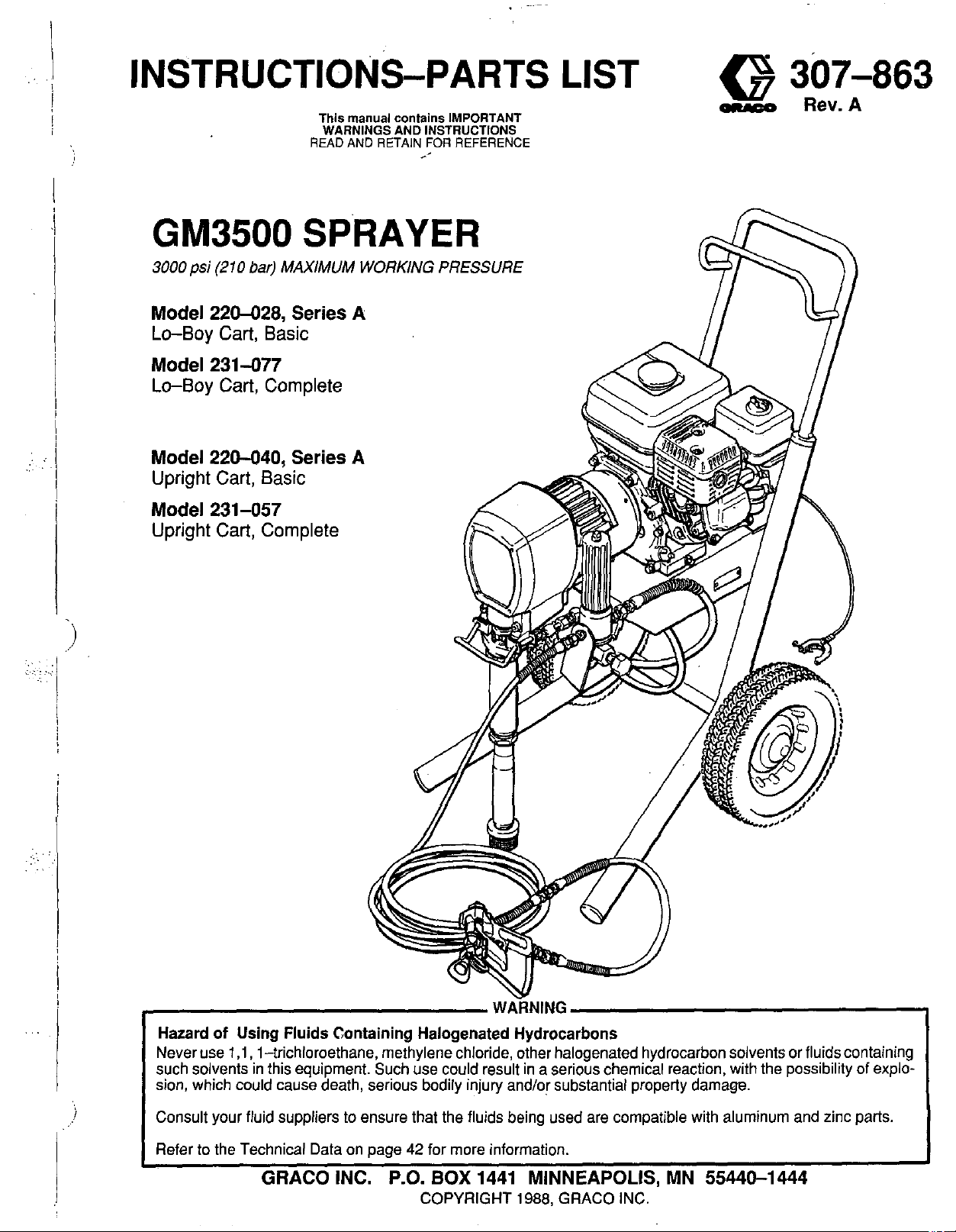
GM3500
3000
psi
(210
bar)
Model 220-028, Series
Lo-Boy Cart, Basic
Model 231-077
Lo-Boy Cart, Complete
Model 220-040, Series
Upright Cart, Basic
Model 231-0517
Upright Cart, Complete
SPRAYER
MAXIMUM WORKING
A
A
PRESSURE
WARNING
Hazard
Never use
such solvents in this equipment. Such use could result in a serious chemical reaction, with the possibility of explosion, which could cause death, serious bodily injury and/or substantial property damage.
Consult your fluid suppliers
Refer
of
Using Fluids Containing Halogenated Hydrocarbons
1,1,
I-trichloroethane, methylene chloride, other halogenated hydrocarbon solvents or fluids containing
to
ensure that the fluids being used are compatible with aluminum and zinc parts.
to
the Technical Data
GRACO INC. P.O.
on
page
42
for more information.
BOX
1441 MINNEAPOLIS, MN 55440-1444
COPYRIGHT
1988,
GRACO INC.
Page 2
TABLE
OF
CONTENTS
Introduction
Warnings
English
French (Avertissernent)
Spanish (Advertencia) 8
Setup
Fueling
Startup
Maintenance
Flushing Guidelines
Troubleshooting Guide
Repair
Pressure Control
Pressure Control Calibration
Bearing Housing and Connecting Rod
Drive Housing
Pinion. Clutch. Field. Clam. Enaine
...............................
................................
...................
....................
...................................
..................................
..................................
.............................
.......................
....................
.......................
-
-
..........................
Pinion Housing kemo&
Repairing the Pinion
.................
..............
-
"
.......
..............
INTRODUCTION
2
4
6
10
11
12
14
15
17
19
21
22
24
25
26
Clutch
Engine
Field and Wiring Harness
Clamp
Clutch Housing
Reassembly
Parts Lists and Drawings
Basic Sprayer,
Lo-Bov Cart. Model 220-028
Uprighi Cart,' Model 220-040
Completre Sprayer,
Lo-Bov Cart. Model 231-077
Uprighi CartIModel 231-057
Pinion Assembly
Pressure Control Assembly
Accessories
Dimensions
Technical Data
Warranty
.............................
.............................
.............................
......................
........................
........................
..............................
...............................
............................
.........................
28
29
..............
......
...........
.......
...
I
.......
................
Back Cover
30
31
31
32
34
36
38
38
39
40
41
42
42
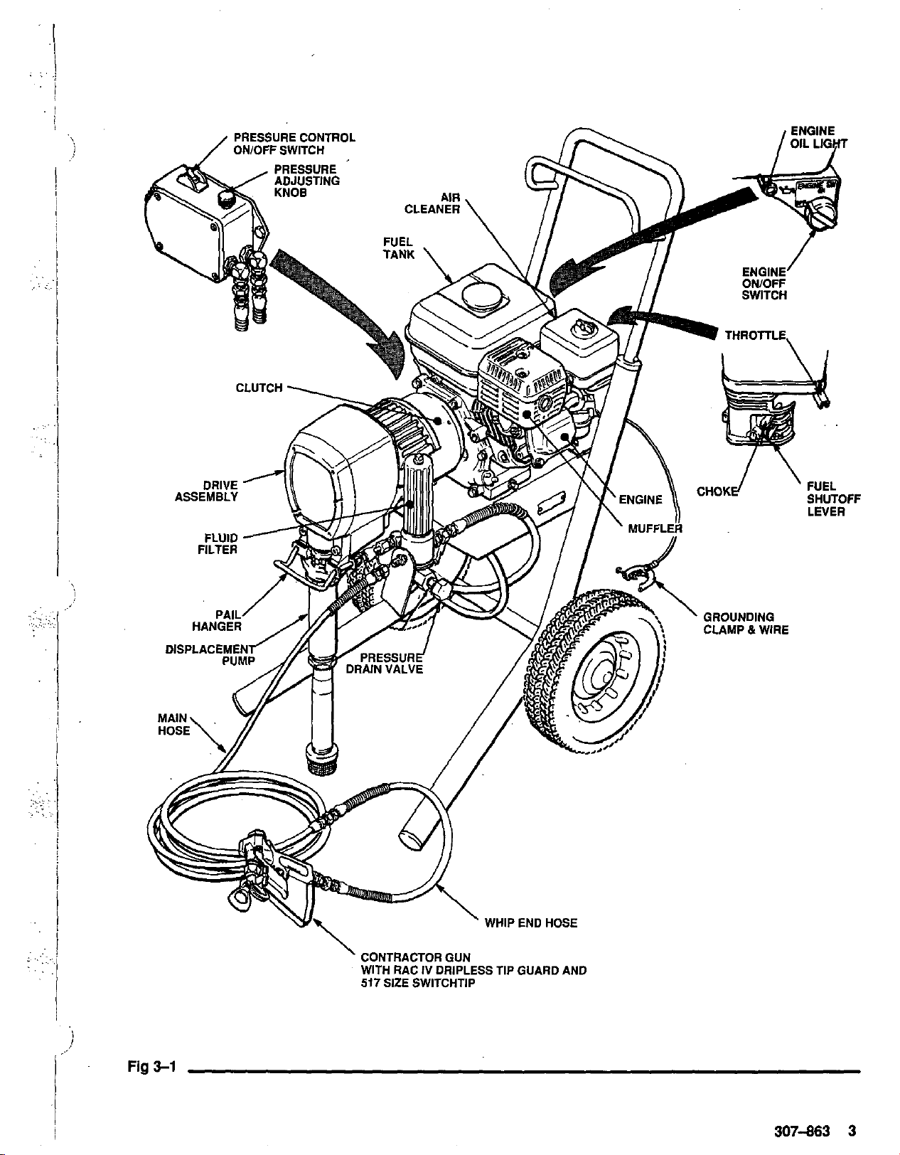
GM3500
The GM3500 Sprayer functions and operates differently
than other airless paint sprayers. Read this section to
help you become familiar with the sprayer before operating it.
Pressure Control
The pressure control includes
sprayer, the pressure adjusting knob, and a pressure
sensing device. The pressure control engages and dis-
engages the clutch to control pressure.
Engine
The engine is a 3.5 horsepower, four stroke gasoline engine. Its function is to drive the displacement pump to
supply paint. An adjustable throttle allows you to adjust
engine speed for large or small
the oil level is too low, the engine shuts
If
you try to start the engine without refilling the oil, a light
illuminates to
gine from damage.
Clutch
The clutch is engaged by the electric power generated by
the gasoline engine.The power is controlled
sure switch.
Drive Assembly
The permanentlygreased drive assembly transfers
power from the gas engine
BASIC
alert
you to the problem and protect the en-
COMPONENTS
an
ON/OFF switch for the
oritice
spray tips. When
off
to
the displacement pump.
(Refer to Fig 3-1)
automatically.
by
the pres-
Fluid Filter
The fluid filter strains the paint to help avoid clogs in the
hose and spray tip. The filter includes a reusable element
and a pressure drain valve for relieving fluid pressure.
Hoses
The grounded, nylon spray hoses have spring guards on
both ends. The 50 foot (1 5.2 m) hose has a 1/11 in. ID. The
3 foot (0.9 m), 3/16 in. ID whip hose allows flexible gun
movement. The nylon hose material acts as a pulsation
dampener to absorb pressure fluctuations.
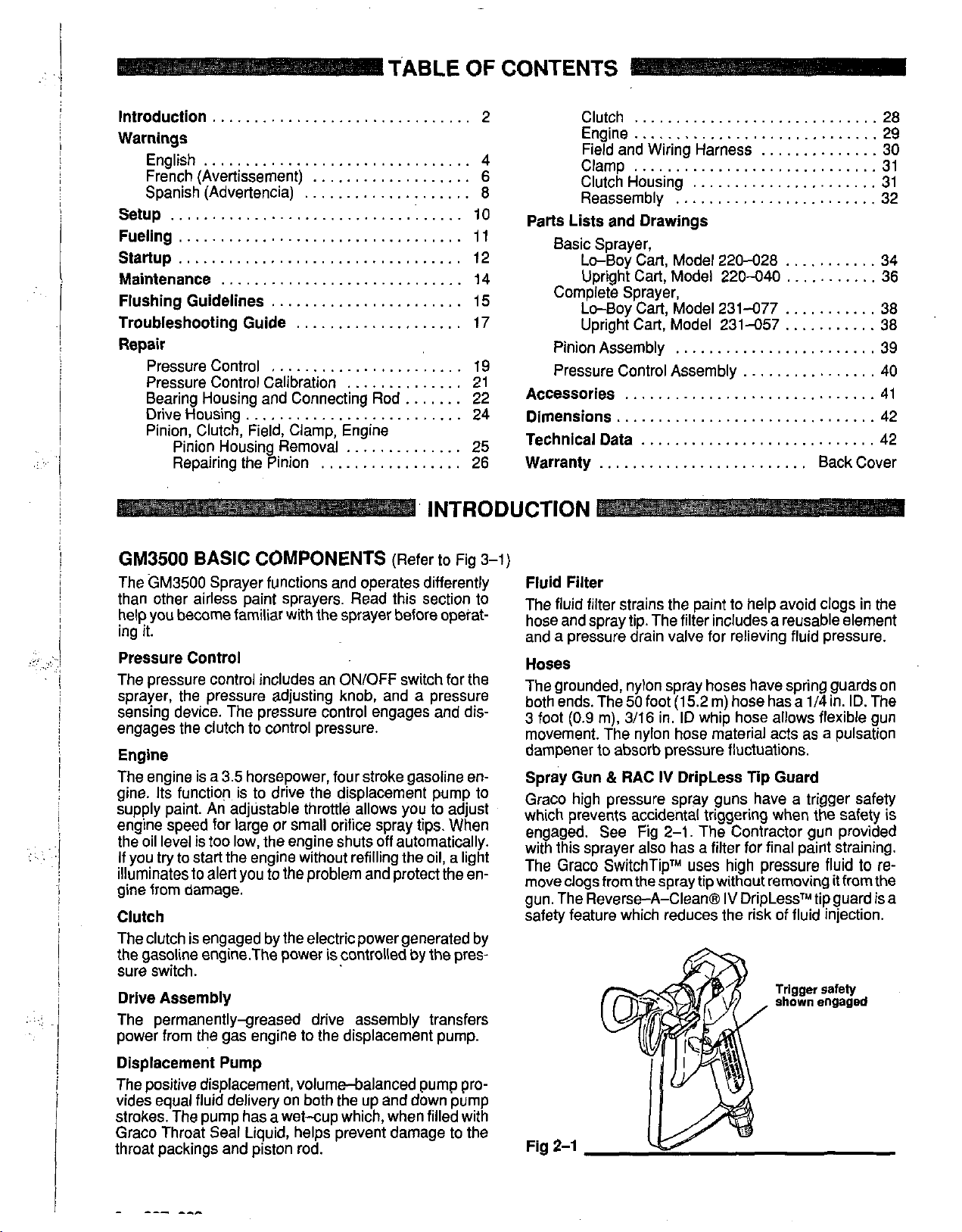
Spray Gun & RAC
Graco high pressure spray guns have a trigger safety
which prevents accidental triggering when the safety is
engaged. See Fig 2-1. The Contractor gun provided
with this sprayer also has a filter for final paint straining.
The Graco SwitchTipTM
move clogs from the spray tip without removing
gun. The Reverse-A-Clean@
safety feature which reduces the risk of fluid injection.
IV
DripLess Tip Guard
uses
high pressure fluid to
IV
DripLessTM tip guard is a
it
from the
re-
Displacement Pump
The positive displacement, volumebalanced pump provides equal fluid delivery on both the up and down pump
strokes. The pump has a wet-cup which, when filled with
Graco Throat Seal Liquid, helps prevent damage to the
throat packings and piston rod.
Page 3
..
. .
I
I
,
,.
i
'
CONTRACTOR
WITH
RAC
517
SIZE SWITCHTIP
i
Fig
3-1
i
GUN
IV
DRIPLESS TIP GUARD AND
307-863
3
Page 4

HIGH PRESSURE SPRAY CAN CAUSE SERIOUS INJURY.
FOR
PROFESSIONAL USE ONLY. OBSERVE ALL WARNINGS
Read and understand all instruction manuals before operating equipment.
FLUID INJECTION HAZARD
General
This equipment generates very high fluid pressure. Spray from
the gun, leaks or ruptured components can inject fluid through
yourskin and into your body andcauseextremely serious bodily
injury, including the need for amputation. Also, fluid injected or
splashed into the eyes or
age.
NEVERpointthespraygunatanyoneoratanypartofthebody.
NEVER put hand or fingers over the spray tip. NEVER try
"blow back" paint; this is NOT an air spray system.
ALWAYS have the tip guard in place
spraying.
ALWAYSfoliowthe Pressure Relief Procedure, below, before
cleaning or removing the spray tip or servicing any system
equipment.
NEVER try
Besureequipmentsafetydevicesareoperating
each use.
Medical Alert-Airless
If
any fluid appears
MEDICAL CARE AT ONCE.
CUT. Tell the doctor exactly what fluid was injected.
NotetoPhvsician:lniectionintheskinisatraumaticiniurv.It
is importah
Do
cern with some exotic coatings injected directly into the
blood stream. Consultation with
constructive hand surgeon may be advisable.
Spray
Be
each use. DO not remove or modify any part
cause a malfunction and result in serious bodily injury.
Safety
on
the skin can cause serious dam-
to
on
the spray gun when
to
stop or deflect leaks with your hand or body.
properly before
to
Spray
penetrate your skin, get EMERGENCY
to
treat
the
not
delay treatment
Gun
sure all gun safely devices are operating properly before
Safety
injury surgically as
to
research toxicity. Toxicity
Devices
Wounds
DO
NOT TREAT AS A SIMPLE
as
possible.
is
,~
a con-
soon
a
plastic surgeon or re-
oi
the gun-this can
,~~-
Safety
Latch
Wheneveryoustopspraying,evenforamoment,alwayssetthe
gun safety latch in the closed or "safe" position, making the gun
inoperative. Failure
tal triggering of the gun.
Diffuser
The gun diffuser breaks up spray and reduces the risk of fluid
injection when the tip is
regularly. Follow the
remove the spray tip.
gun firmly
the gun.
stream, replace the diffuser immediately.
Tip
ALWAYS have the tip guard in place
spraying. The tip guard alerts you
and helps reduce, but does not prevent, the risk of accidentally
placing your fingers or any part of your body close
tip.
Trigger
Always have the trigger guard in place
ing
dropped or bumped.
Spray
Use extreme caution when cleaning or changing spray tips.
the spray tip clogs while spraying, engage the gun safety latch
immediately, ALWAYS follow the Pressure Relief Procedure
and then remove the spray tip to clean
NEVER wipe off build-up around the spray tip until pressure is
fully relieved and the gun safety latch is engaged.
to
If
the fluid emitted is
Guard
Guard
to
reduce the risk of accidentally triggering the gun
Tip Safety
to
set the safety latch can result in acciden-
not
installed. Check diffuser operation
Pressure Relief
Aim the gun into
the pail. Using the lowest possible pressure, trigger
Procedure,
a metal pail,
not
diffused into an irregular
on
the spray gun while
to
the fluid injection hazard
on
the gun when spray-
below, then
holding the
to
the spray
if
it
is
If
it.
Pressure
To
reduce the risk of serious bodily injury, including fluid injec-
tion. splashing fluid or solvent in the eyes or
iuryfrommovingpartsorelectricshock,alwaysfollowthispro-
cedure whenever you shut
servicing any part of the spray system, when installing, cleaning or changing spray tips, and whenever you stop spraying.
1.
2.
Turn the ON/OFF switch
3.
Relief
Engage the gun safety latch.
Flip the pressure control switch
Procedure
off
the sprayer, when checking or
to
OFF.
1
on
the skin, or
to
OFF. or that pressure has
in-
2
4.
Disengage the gun safety latch. Hold a metal part of the
gun firmly
the gun
5.
Engage
6.
Open the pressure drain vaive, having a container ready
to
catch the drainage. Leave the valve open until you are
ready
7.
Disconnect the spark plug cable
lfyoususpectthatfhespraytiporhoseiscorn
stepsabove, VERY SLOWLY loosen the tip guard retaining
nut or hose end coupling and relieve pressure gradually, then
to
the side of agrounded metal pail, andtrigger
to
relieve pressure.
the
gun
safety
latch.
to
spray again.
not
been fully relieved ager fokwing the
.
Now clear the tip or hose.
letel clogged,
Page 5
I
....
,.
. .
i
!
I
!
.,
.
..
MOVING PARTS HAZARD
Moving parts can pinch or amputate your fingers or other body
parts. KEEP CLEAR of moving parts when starting or operating
the sprayer. Follow the Pressure Relief Procedure on page
before checking or servicing any part ofthe sprayer, to prevent it
from starting accidentally.
4
EQUIPMENT MISUSE HAZARD
General Safety
Any misuse of the spray equipment or accessories, such as
overoressurizino. modifvino Darts. usino incomoatible chemicals'and fluids,-or using worn or damaged parts, can cause
to
them
or
property damage.
NEVER alter or modify any part of this equipment; doing
could cause it
CHECK all spray equipment regularly and repair or replace
worn or damaged parts immediately.
Always wear protective eyewear, gloves, clothing and respirator as recommended by the fluid and solvent manufacturer.
rupture and result in fluid injection, splashing in the eyes
on
theskin, orother serious bod~ily injury..orfire. exolosion or
to
System Pressure
This sprayer can develop
WORKING PRESSURE. Be sure that all spray equipment and
accessories used are rated to withstand this pressure.
exceed the maximum working pressure of any component or
accessory used in the system.
Fluid
and
BE SURE that all fluids and solvents used are chemically compatible with the wetted parts shown in the TECHNICAL DATA
on page 42. Always read the fluid and solvent manufacturer's
literature before using them in this sprayer.
Solvent Compatibility
1
I.~~~.
malfunction.
~ ~~~
3000
psi (210 bar) MAXIMUM
-
DO
~ ~
so
NOT
If
High pressure fluid in the hoses can be very dangerous.
hose develops a leak, split or rupture due
damage or misuse, the high pressure spray emitted from it can
cause a fluid injection injury or other serious bodily injury or
property damage.
ALL FLUID HOSES MUST HAVE SPRING GUARDS ON
BOTH ENDS! The spring guards help protect the hose from
kinks or bends at or close
hose rupture.
TIGHTEN all fluid connections securely before each use. High
pressure fluid can dislodge a loose coupling or allow high pressure spray
NEVER use
tire hose for cuts, leaks, abrasion, bulging cover, or damage or
movement
ist. replace the hose immediately.
pressure hose or mend it with tape or any other device.
paired hose cannot contain the high pressure fluid.
HANDLE AND ROUTE HOSES CAREFULLY.
hoses
and hot surfaces of the pump and
or solvents which are not compatible with the inner tube and
to
be emitted from the coupling.
a
damaged hose. Before'each use, check the en-
of
the hose couplings.
to
move equipment. Keep
to
the coupling which can result in
If
DO
hoses clear of moving
gas engine.
to
any kind of wear,
any of these conditions ex-
NOT try
to
recouple high
Do
not pull on
Do
not use fluids
the
A
re-
parts
coverofthehose.DONOTexposeGracohosetotemperatures
above
180'
F
(82'
C)
or below
Hose
Groundlng Continuity
Proper hose grounding continuity is essential to maintaining a
grounded spray system. Check the electrical resistance of your
fluid hoses at least once a week.
on
it which specifies the maximum electrical resistance,
tag
contact the'hose supplier or manufacturer for the maximum resistance limits. Use a resistance meter in the appropriate range
for your hose to check the resistance. lfthe resistance exceeds
the recommended limits, replace it immediately. An ungrounded or poorly grounded hose can make your system hazardous. Also read FIRE
OR
40' F (-40'
If
your hose does not have a
EXPLOSION HAZARD.
C).
..
,
,
...
..~
. ..
,.
..
..
.
.
..
FIRE
Static electricity is created by the flow of fluid through the pump
and hose.
grounded, sparking may occur, and the system may become
hazardous.
plugging a
Sparks can ignite fumes from solvents and the fluid being
sprayed, dust particles and other flammable substances,
whether you are spraying indoors or outdoors, and can cause a
fireor explosion and serious bodilyinjury and property damage.
If
while using this equipment, STOP SPRAYING IMMEDIATELY. Check the entire system for proper grounding.
use the system again until the problem has been identified and
corrected.
Grounding
To reduce the risk
other spray equipment used
CHECKyourlocalelectricalcodefordetailedgroundinginstruc-
lions for your area and type of equipment. BE SURE
all of this spray equipment:
.
1. Sprayer: connect a ground wire and clamp (supplied)
GASOLINE ENGINE HAZARD
NEVER
spilled
ALWAYS pour fuel in slowly
OR
NEVER operate the engine in a closed building unless the engine exhaust is piped outside. The exhaust contains carbon
monoxide, a poisonous, odorless and invisible gas which can
cause serious illness and even death
OR
EXPLOSION HAZARD
If
every part of the spray equipment is not properly
Sparking may also occur when
power supply
you experience any static sparking
of
true earth ground.
fill
the fuel tank while the engine is running or hot. fuel
on
a hot surface can ignite and cause a fire.
EXPLOSION HAZARD, above, and FUELING
cord or using a
static sparking, ground the sprayer and all
or
located in the spray area.
to
avoid spilling. Also read FIRE
plugging
gasoline engine.
or
even
if
inhaled.
in or un-
a slight shock
Do
not
to
ground
to
a
on
page 11.
2.
Fluid
hoses: use only grounded hoses with a maximum
of
500feet(l50m)combinedhoselengthtoensuregrounding
continuity. See Hose Grounding Continuity,
3.
Spraygun:obtain grounding through connection
erly grounded fluid hose and sprayer.
4.
Object being sprayed: according
5.
Fluid
supply container: according to local code.
6.
All solvent
code. Use only metal pails, which are conductive.
dace the oail on a non+onductive surface, such as oaoer
or cardboard, which interrupts the grounding continuity.
7.
To
maintain grounding continuity when flushing or relieving
pressure, always hold a metal part of the gun firmly
side of a grounded metal pail, then trigger the gun.
pails
used
when flushing, according to local
to
local code
to
a prop-
Do
to
not
the
Flushing Safety
Reduce the risk of fluid injection injury. static sparking, or
splashing by following the flushing procedure given
of
this manual. Follow the Pressure Relief Procedureon page
4, and remove the spray tip before flushing. Hold ametal part of
the gun firmly to the side of a grounded metal pail and use the
lowest possible fluid pressure during flushing.
on
page 14
IMPORTANT
United States Government safety standards have been
adopted under the Occupational Safety and Health Act. These
standards-particularly theGeneral Standards, Part 1910, and
the Construction Standards. Part 1926 -should be consulted.
.)n7
om
e
Page 6
AVERTISSEMENT
La
pulv6risation
RBserv6
exclusivement I'usage professionnel. Observer toutes
Bien lire et bien comprendre tous
B
haute
pression
peut
causer des blessures tr6s graves.
les
consignes de s6curit6.
les
manuels d'instructions avant d'utiliser
le
mat6riel.
RISQUES
D'INJECTION
Consignes g6nerales de s6curitB
Cet appareil produit un fluide B tr& haute pression. Le fluide
pulvbrisb par le pistolet ou le fluide sous pression provenant de
fuites ou de ruptures peut ptin&rer sous la peau ou
du
corps et entrainer des blessures trh graves, voir m&me une
amputation. MBme sans &re sous pression, le fluide bclabous-
Sant
ou entrant dans les yeux peut aussi entrainer des
blessures graves.
NE JAMAIS pointer le pistolet vers quelqu'un ou vers une partie quelconque du corps. NE JAMAIS mettre la main ou les
doigts sur I'ajutage du pulvbrisateur. NE JAMAIS essayer de
"refouler" la peinture. Cet appareil N'est PAS un compresseur
pneumatique.
TOUJOURS garder la protection de I'ajutage en place sur le
pistolat pendant la pulv6risation.
A
TOUJOURS observer la March
Pression donnbe plus loin, avant de nettoyer ou d'enlever
I'ajutage du pulvbrisateur, ou d'effectuer un travail quelcon-
que sur une partie de I'appareil.
NE JAMAIS essayer darrhter ou de
main ou le corps.
Avant chaque utilisation, bien s'assurer que 18s dispositifs de
dcuritb fonctionnent correctement.
Suivre pour DBtendre la
d&i&
B
I'intbrieur
les fuites avec la
Soins mBdicaux
En
cas
IMMEDIATEMENT
D'URGENCE. NE PAS SOIGNER CETTE BLESSUAE
COMME UNE SIMPLE COUPURE.
Dispositifs
Avant chaque utilisation, bien s'assure que tous 18s dispositifs
de sbcuritb du pistolet fonctionnent correctement. Ne pas
de penetration de
Avls
au medecin: La pdndirarion
esi
un
chlrurglcalement cene blessure immBdiatement.
pas reiarder le traiiemeni pour effeciuer des recherches sur
la
ioxicii.4. ceriains rev6iements exotiques soni dangereuse-
ment toxiques quand
sang.
ou
iraumaiisme.
I/
est souhaitable de consulrer
un
chirurgien sp6cialis6 dans
de
skurite du
fluide
MUS
DES
II
ils
soni injecibs directement dans le
la peau: DEMANDER
SOlNS MEDICAUX
des
fluides
sous
est
important
un
chirurgien estheiique
la
reconstruction des mains.
pistolet
de
la
peau
traiter
Ne
enlever
querait d'entrainer un mauvais fonctionnement et des
blessures graves.
A chaque fois que l'on s'arr8te de pulvtiriser, m&me s'il s'agit
d'un court instant, toujours mettre
pistolet sur la position "fermbe" ou "sbcurit6" I"safe") pour
emp&cher le pistolet de fonctionner. Si le verrou de &curite
n'est pas mis, le pistolet peut se dbclencher accidentellement.
Verrou
ni
modifier une partie quelconque du pistolet; ceci ris-
de
s6curii6
le
verrou de sbcuritb du
Diffuser
Le diffuseur du pistolet sert B diviser le jet et B rbduire les ris-
ques d'injection accidentelle quand I'ajutage n'est pas en
place. Vbrifier le fonctionnement du diffuseur rbgulibrement.
Pour cette vbrification, dtitendre la pression en observant la
Marche
loin puis enlever I'ajutage du pulvbrisateur. Pointer le pistolet
dans un seau en mbtal, en le maintenant fermement contre le
seau. Puis, en utilisant la pression
puyer sur
diffuse
le diffuseur.
Protection de l'ajutage
TOUJOURS maintenir la protection de I'ajutage en place sur le
pistolet du pulvbrisateur pendant
tion de I'ajutage attire I'attention sur les risques d'injection et
contribue
ou une partie quelconque du corps ne passent accidentelle-
ment
Consi nes de s6curitB concernant
pulvBr
Faire extrhement attention B l'occasion du nettoyage ou du
remplacement des ajutages du pulvbrisateur. Si I'ajutage se
bouche pendant la pulvbrisation, mettre immbdiatement le
verrou de sbcuritb du pistolet. TOUJOURS bien observer la
Marche
I'aiutaae du pulvbrisateur Dour le nettover.
NE
du pulvbrisateur avant que
tomb& et we le verrou de sbcuritb du pistolet ne soit engag
9
Suivre pour DBtendre
la
gachette du pistolet. Si le fluide projet6 n'esipas
sous
forme de jet irrtigulier, remplacer immediatement
B
rbduire, mais n'bvite pas le risque, que les doigts
B
proximitb immediate de I'ajutage du pulvtirisateur.
B
sateur
A
Suivre pour DBtendre
..
JAMAIS essuyer ce qui s'est accumulb autour de I'ajutar
la
la
Pression donnbe plus
la
plus faible possible, ap-
la
pulvbrisation. La protec-
I'ajutage
la
Pression puis eniever
pression ne soit complbtemel
du
38
nt
8.
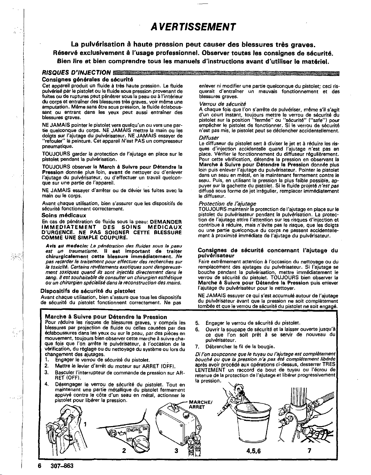
Marche B Suivre
Pour reduire Ies risques de blessures graves, y compris les
blessures Par projection de fluide
Bclaboussures dans Ies yeux ou sur la peau, par des pieces en
mouvement, toujours bien observer cette marche
que fois que I'on arrbte le pulvbrisateur,
vbrification, du rbglage ou du nettoyage du systbme ou lors du
changement des ajutages.
1.
Engager le verrou de sbcuritb du pistolet. bouch8
2.
Menre le levier d'arr€t du moteur sur ARRET IOFFI.
3.
Bascub I'interrupfeur de commande de pression sur AR-
RET IOFFI.
4.
Dbsengager le verrou de sbcuritb du pistolet. Tout en
maintenant une partie m6tallique du pistolet fermement
appuy6 contre le c6te d'un seau en mbtal, actionner le
6
307-863
pour
DBtendre
OU
libbrer la pression.
la
Pression
celles causks par des
B
Suivre cha-
B
I'occasion de la
5.
Engager le verrou de sbcuritb du pistolet.
6.
Ouvrir la soupape de sbcuritb et la laisser ouverte jusqu'i
ce que l'on soit pret
pulvbrisateur.
,,
Dbbrancher
iron
soupconne que le tuyau
aprbs avoir procbdti aux opbrations ci-dessus. desserrer TREI
LENTEMENT un raccord de bout de tuyaU ou I'bCrOU dt
retenue
ou
de
que
la
,e
fii
de
la
pression n'a
A
SB
servir de nouveau dl
la
bougie,
ou
hjutage esi complbtemen
pas
6id
comp~&ernent
de I'alutage et libbrer progressivemen
lib&&
7
Page 7
RISQUES
Consignes
Toute utilisation anormale de I'appareil de pulverisation
accessoires comme. par exemple,
excessive, 18s modifications de pieces, I'utilisation de produits chimiques et de matieres incompatibles et l'utilisation
de pieces usees ou abimees peut causer des dbgats
pareil
ou
liquide
plosion
Toujours porter une protection pour les
vdtements protecteur et un dispositif pour la respiration cor-
respondant aux recommandations des fabricants de fluides
EN
CAS DE MAUVAISE UTlLlSATlON W MATERIEL
g4n6rales
de
s4curit6
la
mise sous une pression
ou
B
des ruptures de pieces et entrainer une injection de
ou
d'autres blessures serieuses, un incendie, une ex-
ou
d'autres dbg8ts.
yeux,
des gants, des
des
I'ap-
et
Pression
Ce pulverisateur peut produire une
TRAVAIL
210
bar
13wO
Ib/po.2/.
Blements du pulverisateur et ses accessoires sont concus pour
resister
NE PAS depasser
B
la
pression maximum de travailide ce pulverisateur.
la
pression maximum de travail d'aucun des
dements ou accessoires utilises avec cet appareil.
compatibilit4
chimique
BIEN S'ASSURER que tous
sont chimiquement compatibles avec les parties mouill6es
diquees dans les "DonnBes techniques", au dos de
ture. Toujours lire soigneusement
PRESSlON
MAXlMUM
S'assurer que tous les
des
corps
Ies
corps des solvants utilis&
les
documents
et
DE
in-
la
couver-
brochures
solvants. du fabricant des fluides et solvants utilises avant de s'en servir
dans ce pulvbrisateur.
MESURES DE SECURITE CONCERNANT LES TUYAUX FLEXIBLES
B
Le fluide
haute pression circulant dans
trhs dangereux. En cas de fuite sur
B
la
dbchirure ou rupture
mauvaise utilisation,
suite de I'usure. de dbgets
les
projections de fluide haute pression
qui en proviennent peuvent entrainer des blessures graves par
la
penetration sous
peau ou par contact, ainsi que des degits
materiels. -4O'C
TOUS LES TUYAUX FLEXIBLES DOIVENT AVOlR DES
RESSORTS SPIRALE DE PROTECTION AUX 2 BOUTS1 Une bonne continuite de la mise
Les spirales de protection contribuent
pliures. de boucles ou de nceuds sur
entrainer
la
rupture du tuyau B,I'endroit du raccord ou B son fluides et d air, au moins une fois par semaine. Si votre tuyau
voisinage.
SERRER
tion,
desserrC
FERMEMENT
Le
fluide
ou
produire
sous
pression
un
jet
les
raccords
peut
a
haute pression s'echappant
raccord.
NE JAMAIS utiliser un tuyau endommage. NE PAS essayer de
refaire le raccord d'un tuyau haute pression ni de reparer le
tuyau avec du ruban adhesif ou par tout autre moyen. Un
tuyau reparb ne peut pas resister au fluide sous pression.
les
tuyaux peut atre MANIPULER LES TUYAUX AVEC PRECAUTION ET
18
tuyau, de fissure, CHOlSlR SOIGNEUSEMENT LEUR CHEMIN. Nepasdeplacer
ou
d'une
le fluide en tirant sur
le
tuyau. Ne pas utiliser de fluides
solvants qui ne sont pas compatibles avec I'enveloppe interieure ou exterieure du tuyau. NE PAS exposer le tuyau
des temperatures supdrieures
B
82°C
f180°FI
I-4O"FI.
B
Bviter
la
les
tuyaux qui pourraient
formation de
Continuit6
essentielle pour maintenir
vaporisation. Vbrifiez
de
la
mise
la
terre
des
la
B
mise B la terre de I'ensemble de
la
resistance Blectrique de vos tuyaux
tuyaux
la
terre des tuyaux est
ne comporte pas d'btiquette qui precise la resistance Blectri-
avant
faire
&que UtiliSa. que maximum. prenez contact avec le fournisseur de waux
sauter
un
raccord
par
le
ou
la fabricant pour avoir les limites de rkktance maximum.
Utilisez un metre de resistance de la gamme appropriee pour
votre tuyau et verifiez la resistance. Si celle-ci depasse les
limites recornrnand6es. remplacez le tuyau immbdiatement.
A
la
Un tuyau sans m[se
terre ou avec une mise
recte peut entrainer des risques pour votre systeme. Lisez
OU
aussi LES RlSQUES D'INCENDIE
D'EXPLOSION ci-
dessus.
ou
ou inferieures
B
la
terre incor-
de
B
B
B
De I'electricite statique est produite par le passage du fluide
la
grande vitesse dans
pompe et dans les tuyaux. Si toutes les tuyau flexible et
a
pieces de I'appareil de pulverisation ne sont pas convenable-
ment reliees
produire
peuvent
ou
du dbbranchement du cordon d'alimentation ou de I'utilisa-
a
la masse ou
et
I'appareil risque d'btre dangereux. Des etincelles
egalement
se
A
la
produire
terre. des Btincelles peuvent se
a
I'occasion
du
branchement
tion d'un rnoteur B essence. Les Btincelles sont suffisantes
pour allumer les vapeurs de solvants
et
le
fluide pulverish.
les
fines particules de poussiere ainsi que d'autres substances in-
flammables, quand on pulverise
I'intbrieur ou B I'extbrieur,
et
B
elles peuvent causer un incendie ou une explosion, ainsi que
des blessures graves et des degits materiels. observer le code ou
S'il se produit des Btincelles d'blectricitk statique. ou
reSSentez la moindre decharge,
ARRETEZ
lMMEDIATEMENT
si
vous
LA PULVERISATION. VBrifiez que le systeme entier est bien
mis
la
terre. Ne yous serve2 pas du svsteme avant que le pro-
blerne soit identifie et corrigb. carton car cela interromprait la continuite le
Mise
B
la
terre
ou B la
masse
Pour rbduire les risques de production d'6tincelles d'blectricitb
statique. le pulverisateur et tousles bquipements utilises ou se maintenir
trouvant dans
terre
ou
mise
B
ment, CONSULTER le code
locales.
la
B
zone de pulv6risation doivent atre relies
la
masse. Pour connaitre le detail des instructions de du
la
terre dans la region et le type particulier d'dquipe-
S'ASSURER
que
ou
les rbglementations Blectriques
tOUs
les
equipements
de pu~v&isa- Pour rbduire les risques de blessures par pdnbtration de la
3
la
tion suivants sont bien relies B la terre:
1.
Pu/vdrisateur:
Relier le fil de masses
et
le collier lfournil
B
2.
Pisfolef:
a
la terre.
3,
Tu,,aux
terre, n'utiliser que des tuyaux comportant une mise
et
ayant une longueur maximum combinhe de
4.
R4c;pient d'aliinenrafion:
Realiser la mise B la terre en le raccordant B un
a
un pulverisateur deja convenablement relies
flexibles:
piedsl,
du
Afin d,assurar
Se
de
la
continuite
egalement
mise
terre
observer le code ou
au
paragraphe
des
tuyaux.l,
de
18s
la
mise
B
la
terre
150
,.Con.
rbglemen-
m
tations locales.
5.
Objets, mat.4riel
6,
T~~~
Ies
le code ou les rbglementations locales.
m~ralligues'conducteurs de
sur
une
surface
7.
Pour conserver la confinuif.4 de la mise B la ferre quand
r;nce
le
le
cbte d'un
pistolet,
une
de
cOntre
Mesures
peau et les risques dds aux Btincelles d'blectricitd Statique
aux Bclaboussures, observer la marche B suivre pour
donnee
a
la
page
les
de solvants
non
ou
partie
,,,etallique
SBcurit4
14
ou
surfaces recevant la pulv.4risation:
rbglementations locales.
utilises
pour
le rincage:
~*el~~~~i~i~~,
conductrice
on
en
concernant
de
ce
manuel.
N'utiliserque desseaux
N~
pas
sur
du papier
la
la
du
puis
press;on,
fermement
appuyer
le
Rincage
mettre
mise B la terre.
sur
la
le
observer
le
ou
du
on
toujours
appuyee
detente
ou
rincage
une bonne terre.
RlSQUES
DUS
AUX
MOTEURS
A
ESSENCE
NE JAMAIS remplir le rsservoir de carburant quand le moteur NE JAMAIS faire tourner un moteaur dans un betiment
B
tourne
ou
quand
il
est chaud. Le carburant renversb sur une
surface chaude peut s'enflammer et causer
JOURS verser
renverser. Lire RISQUES D'INCENDIE
le
carburant lentement pour Bviter d'en
OU
un
incedie. TOU-
D'EXPLOSION.
feme
au dehors. Les gaz d'echappement contiennent de I'oxyde de
carbone, un gaz toxique, inodore et invisible qui peut entrainer
des malaises graves ou m&me
moins que les gaz d'echappement ne soient diriges
la
mort se I'0n le respire.
la
307-863 7
Page 8
AD
VERTENCIA
EL ROCIADO A ALTA PRESION PUEDE CAUSAR GRAVES LESIONES.
SOLO
PARA
US0
PROFESIONAL.
Lea y entienda todo
RESPETE
el
manual de instrucciones antes de rnanejar
LOS
AVISOS
DE
ADVERTENCIA.
el
equipo.
PELIGRO
DE
INVECCION
DE
FLUID0
Seguridad general
Este equipo genera un fluido a una presi6n muy aka.
rociado de la pistola,
componentes pueden inyectar fluido en la piel y el cuerpo
causar lesiones extremadamente graves, incluyendo a veces la
necesidad de amputaci6n. Tambidn, el fluido inyectado
salpicado en
NUNCA apuntar la pistola hacia alguien
cuerpo. NUNCA colocar
quilla. NUNCA tratar de "hacer retornar la pintura"; este NO
es un sistema de rociado de aire.
SIEMPRE tener colocado el protector de
pistola mientras se est6 pulverizando.
SIEMPRE seguir el procedimiento de descarga de presi6n.
dado
servicio a cualiquier equipo del sistema.
NUNCA tratar de parar
cuerpo.
Asegurar que todos
esthn funcionando bien antes de cada uso.
Tratarnianto
.
. - .
-
Si pareciera que un poco de fluido penetr6
TRATAMIENTO MEDICO DE URGENCIA
MEDIATO.
COATE.
A
vis0
se causa una lesidn iraumiltica.
quirhrgicamente la lesi6n a la brevedad posible.
demorar el tratamiento para investigar la toxicidad. La
icidad es algo de soma importancia en algunas pinturas
exdiicas cuando se inyectan directamenre al iorrenie
sanguineo. Sir4 convenienie consultar a
cirugia pldstica
10s
m6s
abjo, anies de limpiar o sacar
. . .
.
-. .
-
-
NO
DBcir al medico exactamente cua fluido fue.
a/ medico:
10s
escapes de fluido o roturas de
ojos
puede causar graves daiios.
o
la
mano
o
10s
o
desviar
10s
escapes con
10s
aparatos de seguridad del equipo
rnbdien
. . .
-
-.
-
-
TRATAR LA HERIDA COMO UN SIMPLE
Si
se llega a inyectar este fluido en la pie/
o
reconstruciiva de las menos.
alguna parte del
dedos encima de
la
boquilla en
la
boquilla o de dar
la
mano o el
la
piel, conseguir
Es
importante tretar
un
especialista en
DE
la
tox-
El
10s
y
o
bo-
la
IN-
No
Aparatos de seguridad de la pistola pulverizadora
Asegurar que todos
et6n
funcionando bien antes de cada uso. No sacar ni
modificar ninguna pieza de la pistola pues podria causar el
malfuncionamiento de la misma con las consiguientes leiones
personales.
Pestilo
Cada vez que se deje de pulverizar, aunque sea por un breve
momento, siempre colocar el pestillo de seguridad en la
posici6n "cerrada", lo que deja
hacerlo puede llevar al disparo imprevisto de la pistola.
de
seguridad
Difusor
El
difusor de
el riesgo de inyecci6n cuando no est6 instalada
Revisar con regularidad el funcionamiento del difusor. Seguir
el
procedimiento de descarga de presi6n. dado
y
despuds sacar
met6lico. sostenihdola bien firme contra
presi6n
emitido
inmediato
Protector de
SIEMPRE tener el protector de
pistola mientras se est6 pulverizando. Este protector llama
atencidn contra el peligro de inyecci6n y ayuda a reducir, per0
no evita. la colocaci6n accidental de
parte del cuerpo
Seguridad
Tener mucho cuidado al limpiar
llegara a obstruirse mientras est6 pulverizando, enganchar el
pestillo de
cedimiento
quilla para limpiarla.
NUNCA limpiar
quilla antes de que se haya descargado por completo la
presion
la
m6s
bajo posible, disparar
no
sale disperso en un chorro irregular, reemplazar de
el
difusor.
la
de
la
pistola de inmediato. SIEMPRE seouir el
de
y
el pestillo est6 enganchado.
10s
aparatos protectores de la pistola
la
pistola inoperante.
pistola dispersa el chorro pulverizado y reduce
la
boquilla. Apuntar la pistola a un balde
61.
la
pistola. Si el fluido
Utilizando la
la
boquilla.
mas
El
no
abajo,
boquilla
la
boquilla colocado en la
10s
cerca de la boquilla.
la
boquilla pulverizadora
descarga de presi6n y despubssacar la'bo-
la
acumulaci6n de pintura alrededor de la bo-
dedos o cualquier otra
o
cambiar las boquillas. Si
la
oro-
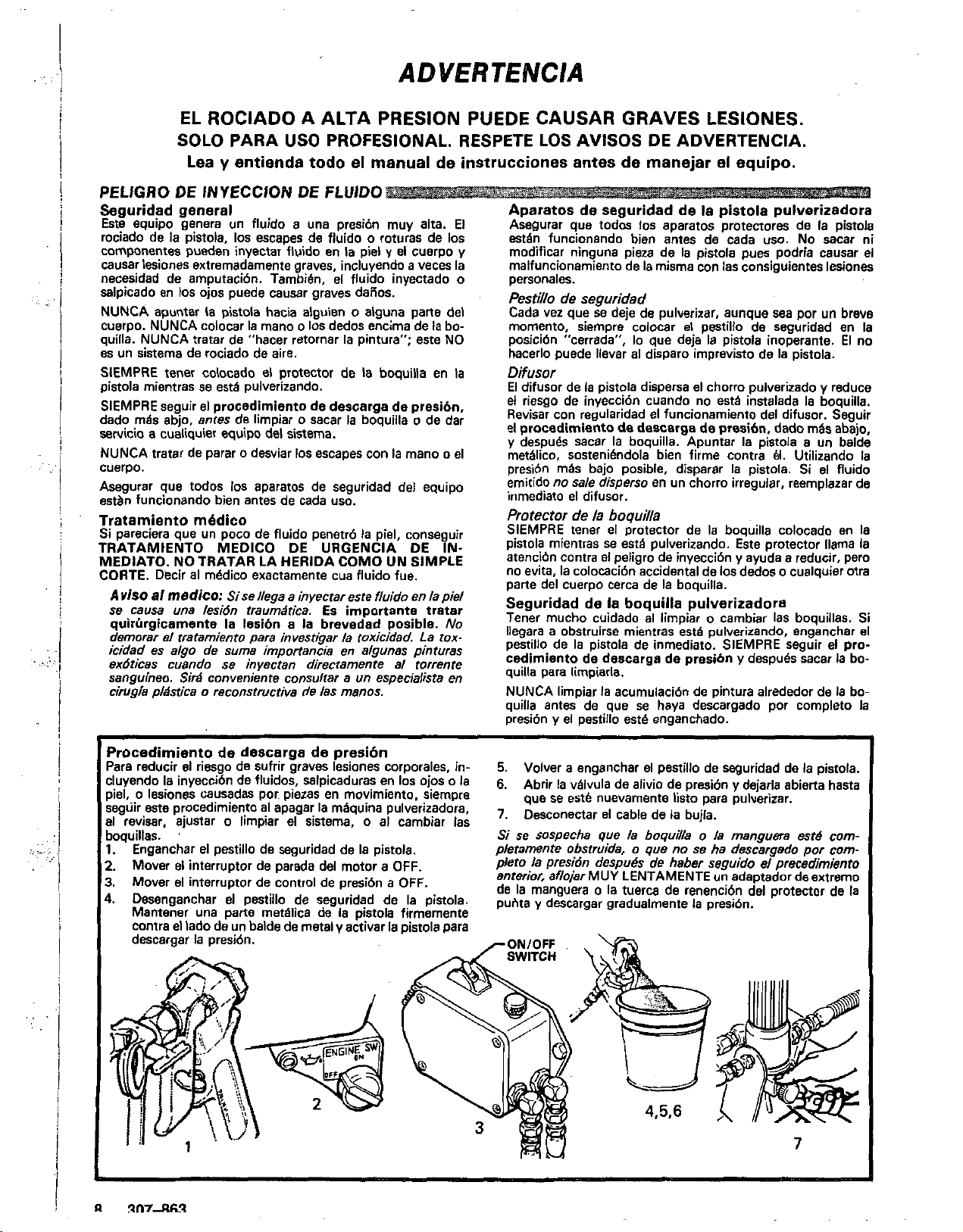
'rocedimiento
'ara reducir el riesgo de sufrir graves lesiones corporales, in:luyendo la inyecci6n de fluidos, salpicaduras en
o
lesiones causadas por. piezas en movimiento. siempre
iel,
ieguir este procedimiento
11
revisar. ajustar o limpiar el sistema, o al cambiar las
,oquillas.
I.
Enganchar el pestillo de sesuridad de la pistola.
!.
Mover
I.
Mover el interruptor de control de presi6n a
I.
Desenganchar e1 pestillo
Mantener una parte met6lica de
contra el lado de un balde de metal
descargar
de
descarga de presi6n
al
apagar la m6quina pulverizadora,
'
el
interruptor de parada del motor a
de
seguridad de la pistola.
la
y
la
presi6n.
anivar la pistola para
10s
ojos o la
OFF.
OFF.
pistola firmemente
L
5.
Volver a enganchar el pestillo de seguridad de la pistola.
6.
Abrir la vhlvula de alivio de presi6n y dejarla abiena hasta
que se est6 nuevamente list0 para pulverizar.
7.
Desconectar el cable de la bujla.
Si
se sospecha que la boquilla o la manguera est6
pleiamente obsiruida,
pleto la presidn despu6s
anterior, aflojar MUY LENTAMENTE un adaptador de extremo
de
la
manguera o la tuerca de renencibn del protector de la
puhta
descargar gradualmenfe
o
we
no
se ha descaraado
de
habw seguido eiprecedimiento
la
presi6n.
Dor
comcom-
7
Page 9

:j
,.
.::.
T
,.
..
.,
....
.. .
.,
.:
..
!
i
PELIGRO
Seguridad general
Cualquier mal us0 del equipo pulverizador
coma sobrepresurizaci6n. modificaci6n de piezhs, us0 de
materiales
de piezas daiiadas
y
causen la inyecci6n de fluido u otras lesiones corporales
graves, incendio, explosi6n
Siempre usar gafas, guantes, vestimetas protectoras
respiradero,
del solvente.
Presi6n
Esta pulverizadora puede desarrollar
PRESION
equipo pulverizador
aguantar
NO exceder la presi6n rnhxima de trabajo de ninghn componente o accesorio de este sistema.
Compatibilidad de
Siempre leer Ias instrucciones del fabricante del fluido
solvente antes de usarlos en esta pulverizadora.
SEGURIDAD EN EL
El fluido que escapa a
ser muy peligroso. Si en la manguera se desarrolla un escape,
una rotura
o
dah
causar una lesibn por inyeccion
graves
ITODAS LAS MANGUERAS PARA FLUIDOS TIENEN
QUE TENER GUARDAS DE RESORTE EN AMBOS EX.
TREMOSl Estas protegen las rnangueras contra dobleces
retorceduras en
podrian traducirse en roturas de
Antes de usarlas, APRETAR bien firmes todas las conexiones.
El fluido a aka presi6n puede desalojar un acoplamiento suelto
o
dejar que por
NUNCA usar una manguera que esth daiiada. Siempre.
revisarla en busca de cortaduras, escapes, abrasidn, cubierta
abultada,
contrarse cualquiera de estas condiciones, reemplazar de in-
mediato
aka presi6n
similar. Una manguera que ha sido remendada no aguante
fluido
MANEJAR
MANGUERAS. No tirar de las mangueras para mover el
equipo.
con el tub0 interno
las mangueras a temperaturas sobre
-40OC
Continuidad
manguera
La continuidad del circuito de puesta a tierra apropiado es
esencial para mantener conectado
pulverizador.
maxima de las mangueras de aire
vez a la semana. Si la manguera no tiene una etiqueta en
cual se especifica la resistencia elbctrica maxima, ponerse en
contact0 con el proveedor
informaci6n sobre
resistencia en
cia; si excede
mediato. Es muy arriesgado tener una manguera sin puesta a
tierra
o
bih la informacidn sobre RIESGO DE INCENDIO
SION,
POR
MAL
US0
DEL EQUIP0
o
10s
accesorios,
y
productos quimicos incompatibles, o utilizaci6n
o
desgastadas. puede hacen que se rompan
0
daiion a la propiedad.
tal
como recomiendan
del
sistema
DE
TRARAJO MAXIMA. Asegurar que todo el
y
la
presi6n mexima de trabajo de esta pulverizadora.
sus accesorios tienen la capacidad para
10s
fabricantes del fluido
210
barias
(3oW
y
psi) de
fluido
US0
DE LAS MANGUERASl
alta
presi6n por las mangueras puede
o
rajadura debido a cualquier tip0 de desgaste.
maltrato. el chorro a aka presi6n emitido por alli puede
o
daiios a la propiedad.
10s
acoplarnientos o cerca de ellos,
BI
escape un chorro a alta presi6n.
o
acoplamientos sueltos o daiiados. Si llegara a en-
la
manguera. NO intentar reacoplar una manguera de
o
enmendarla con cinta adhesiva u otro material
a
aha presi6n.
Y
PASAR CUIDADOSAMENTE LAS
No
usar fluidos o sokentes que Sean incompatibles
y
la cubierta dela manguera. NO exponer
(-40°F).
del
circuito
Es
indispensable revisar la resistencia elbctrica
10s
la
con la puesta a tierra en malas condiciones. Leer tam-
mas
arriba.
limites de resistencia. Usar un metro de
gama apropiada para comprobar
10s
limites recomendados, reemplazarla de in-
u
otras lesiones corporales
la
manguera.
de
puesta
y
de fluido por
o
fabricante de
~~~~ ~~~
@PC
(180OFi o bajo
a
tierra
a
tierra el sistema
lo
menos una
la
manguera para la
la
resisten-
0
EXPLO-
10s
de
tal
un
o
que
el
la
la
PRECAUCIONES PARA
LOS
MOTORES
DE
GASOLINA
NUNCA llenar
fundionando
SUperfiCie caliente puede encenderse
SIEMPRE verter el combustible lentamente para evitar der-
rames. Leer PELIGRO
SION.
y
NUNCA hacer funcionar el motor en un edificio cerrado sin en-
caminar
escape contienen monbxido de carbono, un gas venenoso, sin
olor e invisible que podrla causar enfermedades graves, in-
cluso la muerte, al inhalarse.
o
caliente. El combustible derramado en una
DE
10s
gases de escape hacia el aire libre.
y
INCENDIO 0 EXPLO-
provocar un incendio.
Los
gases de
PELIGRO DE INCENDIO 0 EXPLOSION
El
flujo a alta velocidad del fluido al pasar por la bomba
manguera crea electricidad esthtica. Si todas las partes del
equipo pulverizador no tienen buena tierra, pueden ocurrir
chispas. convirtiendo
y
pueden producirse chispas al enchufar
d6n elbctrico
pueden inflamar
fluido pulverizado, particulas de polvo
flamables, sea a1 aire libre o bajo techo.
una explosi6n
a
la propiedad.
Si ocurre
choque elbctrico mientras se usa el equipo, DEJAR DE
PULVERIZAR DE INMEDIATO. Revisar todo el sistema en
busca de una tierra apropiada.
hasta haber identificado
Puesta a tierra
Para reducir el riesgo de chispas esthticas, conectar a tierra la
puiverizadora
se encuentre en el lugar que
c6digo elbctrico de la localidad para las instrucciones sobre las
conexiones a tierra exigidas para
ASEGURAR de conectar
pulverizador:
1.
pulverizadora: Conectar el alambre de tierra y la abrazadera
lsuministradal
2.
Mangueras para fluidos: usar solamente mangueras con
puesta a tierra de una longitud combinada de
para asegurar buena continuidad a tierra. Referine tambibn al
perrafo sobre continuidad a tierra de
3.
Pistola: hacer
manguera.de fluido
4.
Suministrar on recipiente: de acuerdo al c6digo de la
localidad.
5.
Objeto que se est.4 rociando: de conformidad con el c6digo
local.
6.
Todos
conformidad con el cbdigo local. Usar solamente baldes de
metal, que Sean conductivos. No colocar el balde en una
superficie no conductiva, como papel
la
rumpe
7.
Para mantener la continuidad a tierra durante
descarga de presidn, siempre apoyar una parte methlica de la
pistola bien firme contra el costado de baldedemetal, despu6s
apretar el gatillo.
Seguridad
Para reducir el riesgo de que se inyecte
piel, or que ocurra una descarga de electricidad estatica, siempre seguir las INSTRUCCIONES PARA EL LAVADO, dadas en
la phina
presibn en la phgna
lavar. Apoyar una parte metdlica de
el costado de un balde de metal
posible de fluido durante el lavado.
o
0
una
chispa de electricidad esthtica o incluso
y
a
10s
baldes de solvenre usados durante el lavado, de
continuidad a tierra.
durante
14.
Seguir el procedimiento de descarga
a1
sistema en algo peligroso. Tambih,
al
usar un motor de gasolina. Estas chispas
10s
vapores de
incendio y graves lesiones corporales y daflos
y
solucionado el problema.
todo el otro equipo de pulverizar que se use
se
a
una buena conexi6n a tierra.
la
puesta a tierra conecthndola a una
y
pulverizadora bien conectadas a tierra.
el
lavado
8,
y
quitar
la
o
desenchufar el cor-
10s
solventes y el chorro de
y
otras sustancias
lo
que podria causar
un
No
usar de nuevo el sisterna
va a rociar. CONSULTAR el
la
zona y tip0 de equipo.
tierra todo este equipo
150
m
(500
la
rnanguera.
o
cart6n. que inter-
el
lavado
o
salpique fluido en la
boquilla rociadora antes de
la
pistola bien firme contra
y
usar le presi6n
mhs
y
in-
ligero
o
pies),
o
de
baia
Page 10
..
..
SETUP
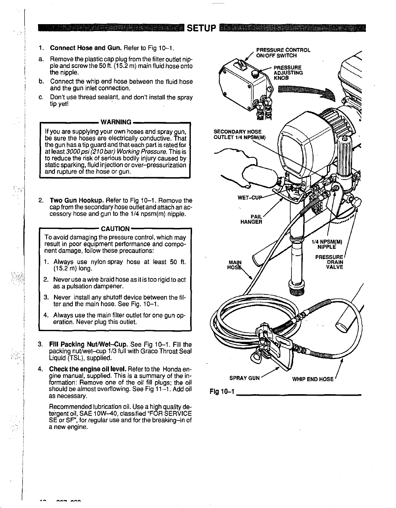
1.
Connect Hose and Gun.
a. Remove the plastic cap plug from the filter outlet nip-
ple and screw the
50
the nipple.
b. Connect the whip end hose beiween the fluid hose
and the gun inlet connection.
c. Don't use thread sealant, and don't install the spray
tip yet!
If you are supplying your own hoses and spray gun,
be sure the hoses are electrically conductive. That
the gun has a tip guard and that each part is rated
at least
3000psi(270bar)
to reduce the risk of serious bodily injury caused by
static sparking, fluid injection or over-pressurization
and rupture of the hose or gun.
2.
Two Gun Hookup.
cap from the secondary hose outlet and attach an accessory hose and gun to the 1/4 npsm(m) nipple.
Refer to Fig 10-1.
ft.
(1
5.2
m) main fluid hose onto
Working
Refer
to
Fig 10-1. Remove the
Pressure.
for
This is
..
.
.,.
..
.
.
. ....
..
.. .
..
.
.
:,:.
..
..
.. ..
..
..
CAUTION
To avoid damaging the pressure control, which may
result in poor equipment performance and compo-
nent damage, follow these precautions:
1.
Always use nylon spray hose at least
(1
5.2
m) long.
2.
Never use a wire braid hose as it is too rigid to act
50
ft.
as a pulsation dampener.
3.
Never install any shutoff device between the
ter and the main hose. See Fig.
10-1.
4. Always use the main filter outlet for one gun
fil-
op-
eration. Never plug this outlet.
3.
Fill
Packing NuWet-Cup.
packing nut/wet-cup
Liquid
(TSL),
4.
Check the engine
supplied.
oil
1/3
level.
gine manual, supplied. This
formation: Remove one of the oil
See Fig 10-1.
Fill
full with Graco Throat Seal
Refer to the Honda en-
is
a summary of the in-
fill
plugs; the oil
should be almost overflowing. See Fig 11-1. Add oil
as necessary.
Recommended
teraent oil.
SE-or
SF;
lubrication oil. Use a high
SAE
1
OW-40.
for regular
classified
use
and forthe breaking-in
"FOR
quality de-
SERVICE
a new engine.
the
of
Fig
10-1
SPRAY
GUN
'
WHIP
END
HOSE
I
Page 11
5.
Be sure your system is properly grounded be-
fore operating it.
tion,
page
6.
Fill
7.
Flush the pump
was left
a. Before using water-base paint, flush with
b. Before using oil-base paint, flush with mineral
FIRE
5.
the gas tank.
in
to
mineral spirits followed by soapy water, and
then a clean water flush.
spirits only.
Read and follow the warning sec-
OR
EXPLOSION
See the
to
protect pump parts after factory testing.
FUELING
remove the lightweight oil which
HAZARD,
section, below.
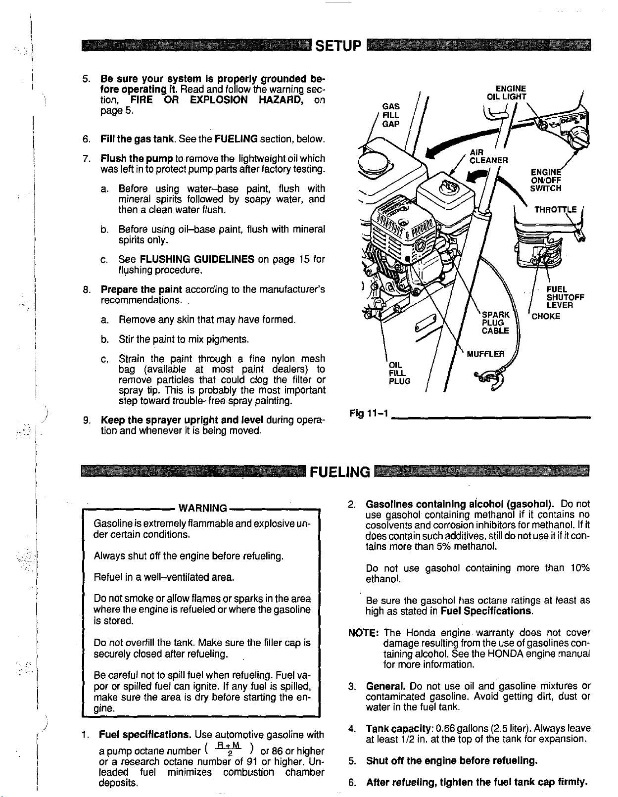
SETUP
on
I.
ENGINE
OIL LIGHT
.. .
c. See
8.
Prepare the paint
recommendations.
a. Remove any skin that may have formed.
b. Stir the paint to mix pigments.
c. Strain the paint through a fine nylon mesh
9.
Keep the sprayer upright and level
tion and whenever it is being moved.
Gasoline is extremely flammable and explosive under certain conditions.
Always shut
Refuel in a well-ventilated area.
FLUSHING GUIDELINES
flushing procedure.
according
bag (available at most paint dealers)
remove particles that could clog the filter or
spray tip. This is probably the most important
step toward trouble-free spray painting.
WARNING
off
the engine before refueling.
on
page 15 for
to
the manufacturer’s
during opera-
to
Fig
FUELING
2.
Gasolines containing aicohol (gasohol).
use gasohol containing methanol
cosolvents and corrosion inhibitors for methanol. If it
does contain such additives, still do
tains more than 5% methanol.
ethanol.
\
11-1
Do
not use gasohol containing more than
/
fi
MUFFLER
//
if
it contains no
not
use it
Do not
if
it con-
10%
Do
not smoke
where the engine is refueled or where the gasoline
is stored.
Do
not overfill the tank. Make sure the filler cap is
securely closed after refueling.
Be careful not to spill fuel when refueling. Fuel vapor or spilled fuel
make sure the area is dry before starting the en-
oine.
1.
Fuel specifications.
a pump octane number
or a research octane number of 91 or higher. Un-
leaded fuel minimizes combustion chamber
deposits.
or
allow flames or sparks in the area
can
ignite. If any fuel is spilled,
Use automotive gasoline with
(
or
86
or higher
Be sure the gasohol has octane ratings at least as
high as stated in
NOTE:
3.
4.
5.
6. After refueling, tighten the fuel tank cap firmly.
The Honda engine. warranty does
damage resulting from the use of gasolines containing alcohol. See the HONDA engine manual
for more information.
General.
contaminated gasoline. Avoid getting dirt, dust or
water in the fuel tank.
Tank capacity: 0.66
at least 112 in. at the top of the tank for expansion.
Shut
Do
off
the engine before refueling.
Fuel Specifications.
not
not
use oil and gasoline mixtures or
gallons (2.5 liter). Always leave
cover
Page 12
STARTUP
NOTE:
Use this procedure each time you start the sprayer to
help ensure the sprayer is ready to operate and that you
start it safely.
NOTE:
1.
2.
NOTE:
3.
4.
5.
6.
7.
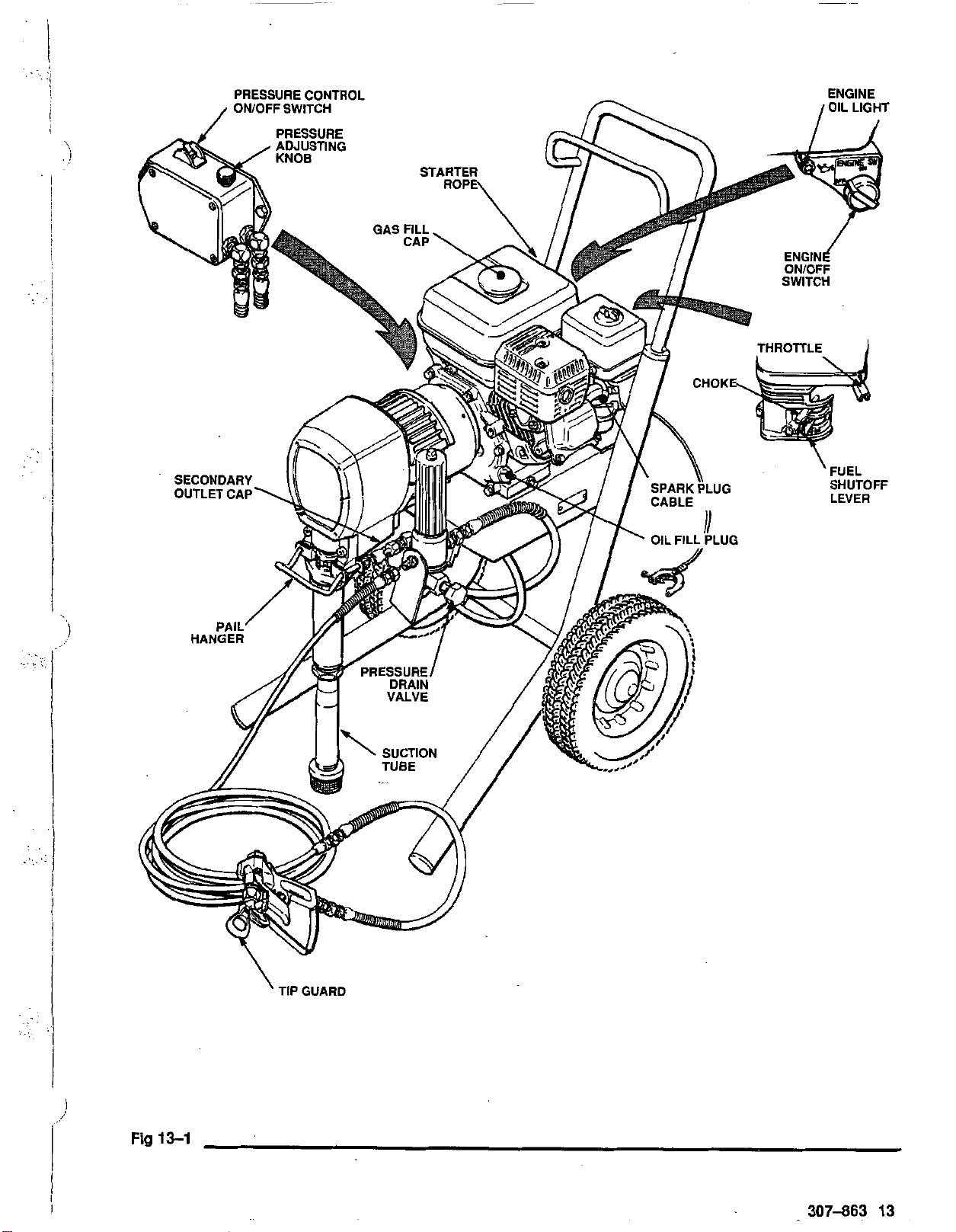
Refer to Fig 13-1 as you start the sprayer. 13.
When starting a sprayer that
move the spray tip.
Check the gas tank.
Check the engine
The engine stops automatically if it is low on oil.
you try to start it again without adding more oil, a
red light on the rear of the engine lights as you
pull the starter rope.
If
a
secondary hose and gun
sure the cap is securely plugging the nipple.
Place the suction tube into the paint container.
Flip the pressure control switch.to OFF.
Open the fuel shutoff lever
rection of the arrow.
Be sure the spark plug cable is firmly pushed
onto the plug.
Open the fuel shutoff valve.
oil
level.
IS
NOTprimed, re-
If
is
not installed,
by pushing it in the di-
be
Open the choke.
leave the choke closed for 10 to 30 seconds before
opening it to keep the engine running. Othelwise,
open the choke as soon as the engine starts.
14.
Disengage the gun safety latch.
15.
To start the pump,
valve. Turn the pressure control switch to ON and
slowly increase the pressure setting until the pump
starts to cycle slowly. Cycle the
fluid is flowing smoothly from the pressure drain
valve, indicating that the pump is fully primed. Close
the pressure drain valve. Holding a metal part of the
gun firmly against and aimed into a grounded metal
container, squeeze the trigger until fluid is flowing
smoothly from the gun. Release the trigger and engage the gun safety latch.
16.
1nstallthespraytipinthegun.Seetheseparatetip
manual, 307-848.
To reduce the risk of serious bodily injury from from
fluid
injection,
the tip guard removed.
TWARNlNGl
In cold weather you may have to
open the filter's pressure drain
pump
NEVER
operate the spray gun with
slowly until
:.
.
..
1:
',:
. .
. ..
CAUTION
Never attempt to start the engine unless fluid pres-
sure
is
relieved and the pressure control ON/OFF
switch is OFF. Trying to start the engine under load
will damage the recoil system.
I
8.
Set the pressure adjusting knob
terclockwise to the lowest pressure setting.
9.
Pull the throttle lever away from the fuel tank
maximum position (fully left).
10.
If
the engine is cold,
gine choke lever, located beneath the air cleaner.
If
the engine Is warm,
1
I
choke only half way or not at all.
11.
Turn the engine switch to ON.
12.
Grasp the starter rope.
hand, pull the rope rapidly and firmly. Continue holding the rope as you let
rope until the engine starts.
Letting the rope return too fast may cause serious
bodily injury if the rope hits someone.
iam the rope in the recoil assemblv.
IWARNINT1
completely close the gray en-
you may need to close the
Holding the frame with one
it
return. Pull and return the
all the way coun-
to
It
could also
17.
Adjust the engine speed and pump pressure.
First set the throttle lever to the maximum RPM set-
ting (fully left). Trigger the gun onto a test paper to
check the spray pattern and atomization. Adjust the
pressure adjusting knob until you get a good pattern.
Then slowly lower the throttle setting as far as you
can without changing the spray pattern.
Always use the lowest possible pressure and throttle
setting to increase the life of the sprayer. Higher settings cause excessive clutch cycling as well as tip
and pump wear.
l-cAuT1oNl
Close the fuel valve whenever
the sprayer
Keep the sprayer upright and level when operating
it and when transporting it.. This prevents crank-
case oil from leaking into the combustion chamber
which makes startup verv difficult.
to
prevent fuel
you are transporting
from flooding the
Page 13
..
..
.i
..
I
Fig
13-1
'
TIP
GUARD
307-863
13
Page 14
MAINTENANCE
1-
WARNING
-1
To reduce the risk of serious bodily injury, including
fluid injection or splashing in the eyes or on the skin,
or injury from moving parts, always follow the
I
sure Relief Procedure Warning
on page
15
before
Pres-
checking, adjusting, cleaning and shutting down the
1
sprayer. Disconnect the spark plug.
DAILY:
DAILY:
AFTER THE FIRST
TION:
WEEKLY:
the element. Replace the element
Check the engine oil level and
fill
as necessary.
Check and fill the gas tank.
20
HOURS OF OPERA-
Drain the oil and refill with clean oil.
Remove the cover of the air filter and clean
if
necessary.
If
operating in an unusually dusty environment, check the filter
daily and replace
Replacement elements can be purchased from your
if
necessary.
lo-
cal Honda dealer.
CAUTION
For
detailed engine maintenance and specifica-
tions, refer to the separate engine manual, supplied.
r
WEEKLY:
ment pump packing nut. Fill it
Check the level of the TSL in the displace-
if
necessary. Keeping TSL
in the nut helps lubricate the packings.
AFTER EACH
100
HOURS
OF
OPERATION:
Change
the oil.
SPARK PLUG:
plug. Gap the plug to
Use only a
0.0250.030
(NGK)
BPGES or
in.
BPRGES
(0.7-0.8
mm).
Be
sure to use a spark plug wrench when installing and removing the plug.
~..
~
..
:
....
:.:.
i
..
.,:.
,.
.... ..
'.,.
. . ..
,
. ~.
:.
.,
..
..
Page 15

FLUSHING GUIDELINES
WARNING
Pressure Relief Procedure
To
reduce the riskof serious bodily injury, includingfluid
injection, splashing fluid or solvent in the eyes or on the
skin, or injury from moving parts or electric shock, always follow this procedure whenever you shut
off
sprayer, when checkina or servicina any Dart of the
spray system, when i&alling, c1eGing-o; changing ready
spray tips, and whenever you stop spraying.
1.
Engage the gun safety latch.
2.
Turn the ON/OFF switch to OFF.
3.
Flip the pressure control switch to OFF.
4.
Disengage the gun safety latch. Hold a metal part of
the
and
the Engage
6.
Open the Pressure drain valve. havina a container
until you are ready
7.
Disconnect the spark plug cable
If
you
clogged, or that pressure has not been
ter following the steps above, VERY SLOWLY loosen
the tip guard retaining nut or hose end coupling and re-
lieve pressure gradually, then loosen completely. Now
clear the tip or hose.
gun
firmly
trigger
the
to
catch the drainage. Leave thij valve open
suspect that the spray tip or hose
the
the
gun
to
gun latch.
to
side
of
a
grounded
relieve
pressure,
spray again.
is
fully
metal
pail,
complete/y
relieved
af-
..
. . ..
...
.
:..,
...
'!::
..
.
..
.
.,:
..
..
1
,
,,
When
1.
to
Flush
New Sprayer.
tory tested
in
lightweight oil which was left in to pro-
Your new
GM3500
tect pump parts.
Before using water-base paint, flush with mineral
spirits followed by soapy water, and then a clean
water flush.
Before using oil-basepaint, flush with mineral spirits
2
Sprayer was fac-
CAUTION
NEVER leave water in the sprayer
if
there is the
slightest chance it could freeze. Push the water out
with mineral spirits. Water left
to
freeze in the pressure control tube prevents the sprayer from being
started and causes serious damage to the pressure
control.
only.
2.
Changing Colors.
Flush with a compatible solvent
6.
Startup after storage.
such as mineral spirits or water.
,
3.
Changing from water-base to oil-base paint.
Flush with warm, soapy water, then mineral spirits.
4.
Changing from oil-base to water-base paint.
Flush with mineral spirits, followed by warm, soapy
Before using water-base paint, flush
spirits with soapy water and then aclean water flush.
When using oil-base paint, flush
out
its with the paint to be sprayed and the sprayer
ready
to
use.
out
mineral
the mineral spir-
is
water, then a clean water flush.
5.
Storage.
Continued on page
16.
Water-base paint: flush with water, then mineral
spirits and leave the pump, hose and gun filled with
mineral spirits. Shut off the sprayer, remove the
I
spark plug cable, and open the pressure drain valve
to
relieve pressure and leave it open.
Oil4asepaint:flush with mineral spirits. Shut
off
the
sprayer, remove the spark plug cable, and open the
pressure drain valve to relieve pressure and leave it
open.
Page 16
I
I
!
,
'.
!
!
i
!
i
~
i
!
.I
:.
.I
!
i
1
!
I
.i
i
I
~
FLUSHING GUIDELINES
How
to
Flush
1.
Follow the
page
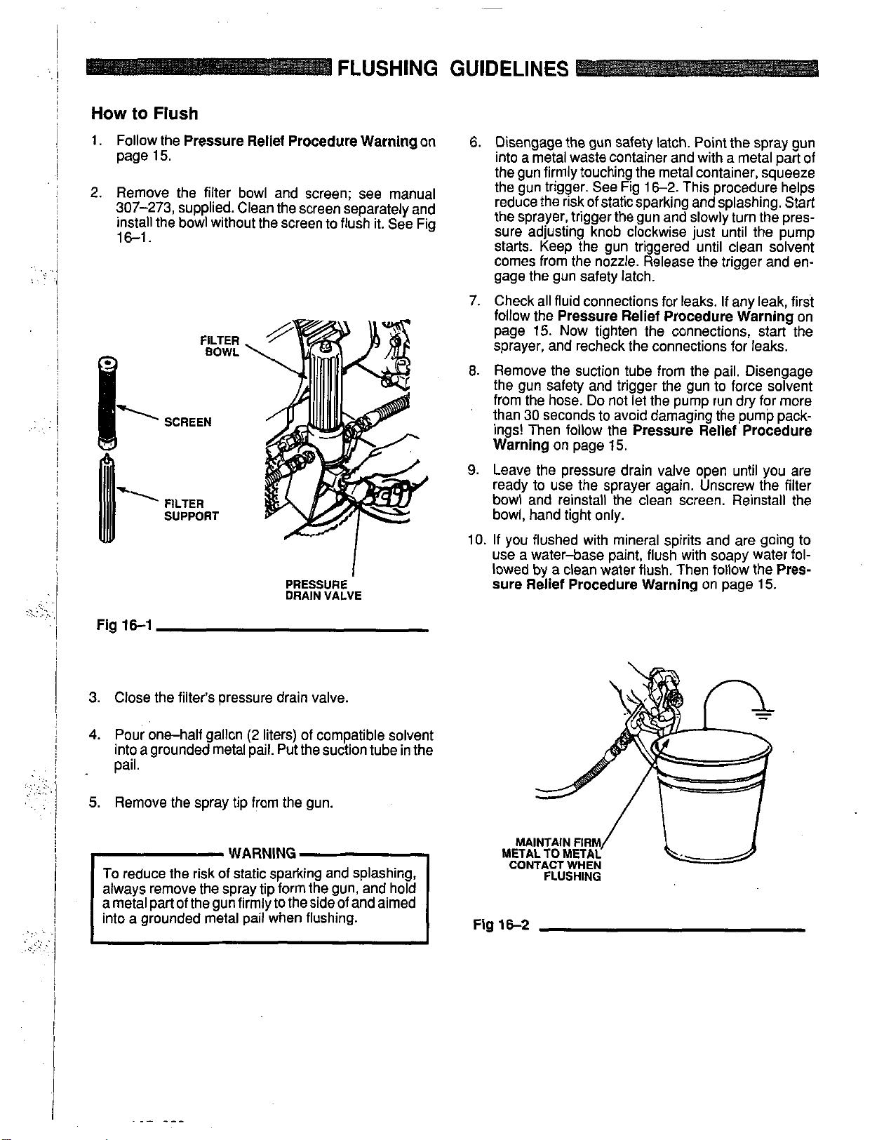
2. Remove the filter bowl and screen; see manual
307-273, supplied. Clean the screen separately and
install the bowl without the screen to flush it. See Fig
16-1.
Pressure Relief Procedure Warning
15.
FILTER
BOWL
SUPPORT
PRESSURE
DRAIN
VALVE
on
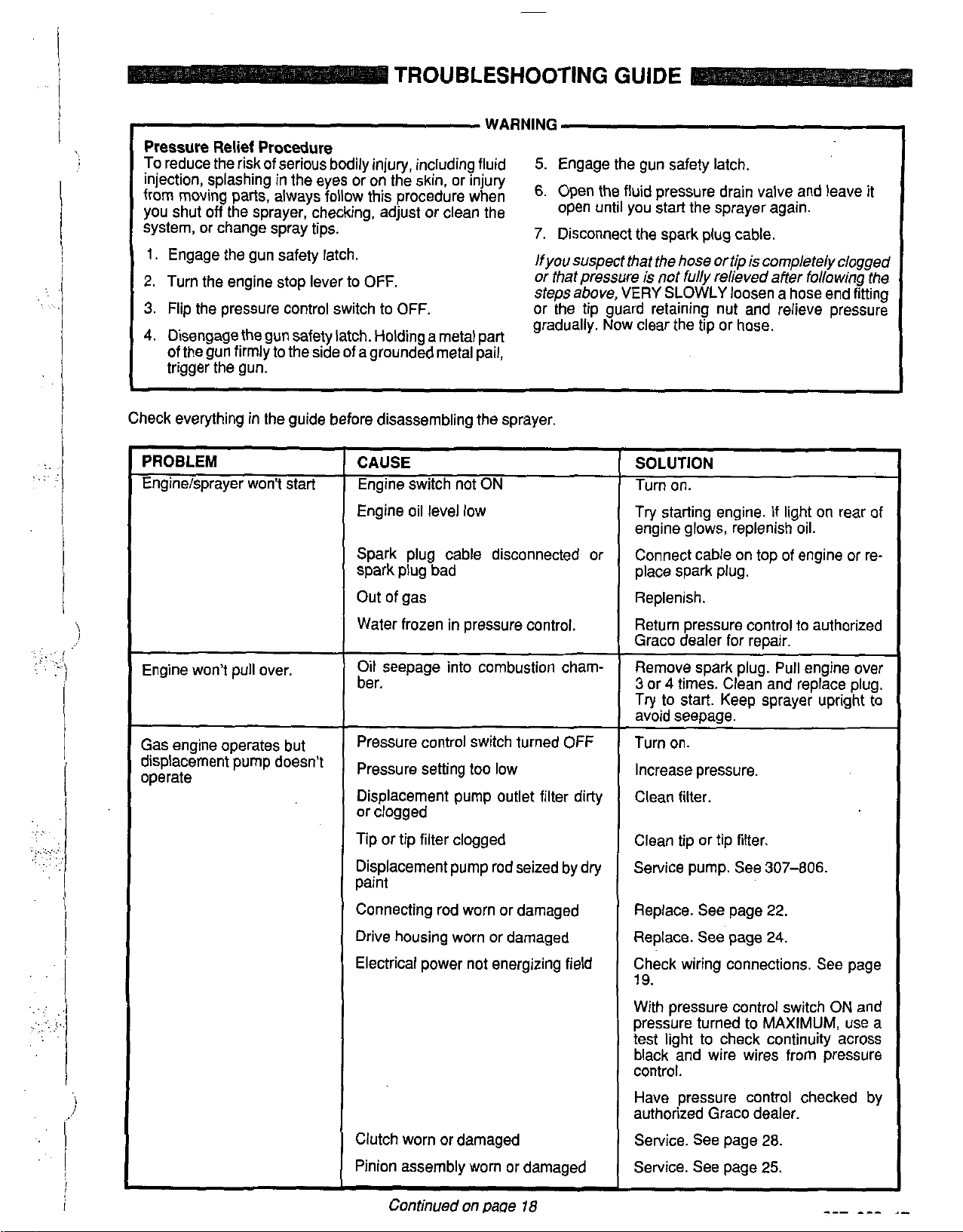
6.
Disengage the gun safety latch. Point the spray gun
into a metal waste container and with a metal part of
the gun firmly touching the metal container, squeeze
the gun trigger. See Fig
of
reduce the risk
static sparking and splashing. Start
16-2.
This procedure helps
the sprayer, trigger the gun and slowly turn the pressure adjusting knob clockwise just until the pump
starts. Keep the gun triggered until clean solvent
comes from the nozzle. Release the trigger and engage the gun safety latch.
7. Check all fluid connections for leaks. If any leak, first
follow the
page
Pressure Relief Procedure Warning
15.
Now tighten the connections, start the
on
sprayer, and recheck the connections for leaks.
8.
Remove the suction tube from the pail. Disengage
the gun safety and trigger the gun to force solvent
from the hose.
Do
not let the pump run dry for more
than 30 seconds to avoid damaging the pump pack-
ings! Then follow the
Warning
9.
Leave the pressure drain valve open until you are
on page 15.
Pressure Relief Procedure
ready to use the sprayer again. Unscrew the filter
bowl and reinstall the clean screen. Reinstall the
bowl, hand tight only.
IO.
If you flushed with mineral spirits and are going to
use a water-base paint, flush with soapy water followed by a clean water flush. Then follow the
sure Relief Procedure Warning
on
page
Pres-
15.
Fig
161
3. Close the filter's pressure drain valve.
4.
Pour
one-half gallon
into
a
grounded metal pail. Put the suction tube in the
(2
liters)
of
compatible solvent
pail.
5. Remove the spray tip from the gun.
WARNING
To reduce the risk of static sparking and splashing,
always remove the spray tip form the gun, and hold
a metal part of the gun firmly to the side of and aimed
into a grounded metal pail when flushing.
Fig
CONTACT
162
WHEN
FLUSHING
Page 17
TROUBLESHOOTING GUIDE
WARNING
Pressure Relief Procedure
To reduce the risk of serious bodily injury, including fluid
injection, splashing in the eyes or on the skin, or injury
from moving parts, always follow this procedure when
you shut off the sprayer, checking, adjust or clean the open until you start the sprayer again.
system, or change spray tips.
I.
Engage the gun safety latch. lfyou suspect that the hose
2. Turn the engine stop lever
3.
Flip the pressure control switch
4.
Disengage the gun safety latch. Holding a metal part
to
OFF.
to
OFF.
of the gun firmly to the side of a grounded metal pail,
trigger the gun.
Check everything in the guide before disassembling the sprayer.
5.
Engage the gun safety latch.
6.
Open the fluid pressure drain valve and leave it
7.
Disconnect the spark plug cable.
ortip
is
cornpletelyclogged
is
or that pressure
not fully relieved affer following the
steps above, VERY SLOWLY loosen a hose end fitting
or the tip guard retaining
nut
and relieve pressure
gradually. Now clear the tip or hose.
..
.
..
:
,..:.
,.:...'
..
,.
....
.,.
:
..
PROBLEM
Engine/sprayer won't start
Engine won't pull over.
Gas engine operates but
displacement pump doesn't
operate
CAUSE
Engine switch
not
ON
Engine oil level low
Spark plug cable disconnected or
spark plug bad
Out of gas
Water frozen in pressure control.
Oil seepage into combustion cham-
ber.
Pressure control switch turned
Pressure setting
too
low
OFF
Displacement pump outlet filter dirty
or clogged
Tip or tip filter clogged
Displacement pump rod seized by dry
paint
SOLUTION
Turn on.
Try starting engine.
If
light
on
rear of
engine glows, replenish oil.
Connect cable on top of engine or replace spark plug.
Replenish.
Return pressure control
to
authorized
Graco dealer for repair.
Remove spark plug. Pull engine over
3
or 4 times. Clean and replace plug.
to
Try
start. Keep sprayer upright
to
avoid seeoaoe.
Turn on.
Increase pressure,
Clean filter
Clean tip or tip filter.
Service pump. See
307-806.
Connecting rod worn or damaged
Drive housing worn or damaged
Electrical power
not
energizing field
Clutch worn or damaged
'inion assembly worn or damaged
~~ ~ ~~
Continued on Raoe
18
Replace. See page 22.
Replace.
See
page 24.
Check wiring connections. See page
19.
With pressure control switch
pressure turned
test light
to
MAXIMUM,
to
check continuity across
ON
use a
and
black and wire wires from pressure
control.
Have pressure control checked by
authorized Graco dealer.
Service. See page 28.
Service. See page 25.
Page 18
~
.(
I
..
!
PROBLEM
Displacement pump outpul
low on upstroke
Displacement pump outpu
low on downstroke or bott
strokes
Paint leaks into wetcup
TROUBLESHOOTING
~~
CAUSE
Pump inlet screen clogged
Piston ball check not seating
Piston packings worn or damaged
Displacement pump sleeve gasket
worn or damaged
Pump inlet screen clogged
Piston packings worn or damaged
Intake valve ball check not seating
properly
Engine RPM too low
Clutch worn or damaaed
~~~~~
Loose wet-cup
Throat packings worn or damaged
GUIDE
~
SOLUTION
Clean.
Service piston ball check.
Replace packings.
Replace.
Clean.
Replace packings.
Clean and service.
Increase throttle setting. See Startup,
Step 17, page 12.
Replace. See page 28.
Tighten just enough to stop leakage.
Replace packings. See 307-793.
Low fluid delivery
Spitting from gun
Displacement rod worn or
damaged
Pump inlet screen clogged
Pressure setting too low
Engine RPM too low
Dirty outlet filter, tip filter or tip
Large pressure drop in hose
Air in fluid pump or hose
Tip partially clogged
Fluid supply is low or empty
Replace. See 307-793.
Clean.
Increase pressure. See Startup, Step
17, page 12.
Increase throttle setting. See Startup,
Step 17, page 12.
Clean,
Use larger diameter hose.
Check for. loose connections at intake
and tighten. Then prime the pump.
See Startup, page
12.
Clear.
Refill and reprime the pump. See
Startup, page 12. Check fluid supply
often
to
prevent running dry.
Page 19

1
s
I
1
Pressure Control Replacement
REPAIR
I
..
. .. .
. .
\
To
reduce the risk of serious bodily injury, including
fluid injection or splashing in the eyes oron the skin,
or injury from moving parts, always follow the
sure Relief Procedure Warning
checking, adjusting, cleaning and shutting down the
sprayer. Dlsconnect the spark plug cable.
1.
Disconnect both hoses at the pressure control
holding the elbows firmly. See the
Take note of the original location of each hose
sure you reassemble them correctly at the end of this
procedure. See Fig
DO
NOTallow the elbow
..
removing or connecting the hoses. Turning the el-
bows can damage the sensitive bourdon tube.
2. Working under the engine mounting plate of the cart,
disconnect the red, black and white wires. Then remove the three nuts
the capscrews
bracket
trol. See Fig 14-2.
(67)
WARNING
Pres-
on page
17
before
(63),
CAUTION
19-1.
CAUTION
(314
OR
315)
to
(61)
and lockwashers
(62)
which hold the pressure control
to
the cart. Remove the pressure con-
below.
to
turn when
(9)
from
be
n-
/
63
B'
(see
page
21)
3. Remove the pressure control cover and screws
(76,64)
to
4.
Remove the wire clamp (32) from the pressure con-
trol wires.
and the fourscrews
the pressure control. See Fig
(65)
holding bracket
19-1.
(67)
Fig
MOUNTlNG FOR UPRIGHT CART SHOWN
19-1
VIEW
FROM
UNDER ENGINE MOUNTING
PLATE ON UPRIGHT CART
VIEW
FROM
UNDER ENGINE MOUNTING
PLATE
ON
LO-EOY
CART
Page 20

REPAIR
5.
Disconnect the wires from the rectifier (307). Re-
move the screw (311). nut (306) and lockwasher
(305).
See Fig 19-1.
6. Unscrew the connector (313 or 316) from the box, lockwashers and nuts (62,9,61) which hold the
pulling the wires out with it. bracket (67) to the cart.
7.
Holding the hex of the adapters
with
a
8.
Remove the screw
the ground wire
..:
RED
remove
(31
0)
(308).
the
and lockwashers (305) from
(A)
e'bows
at the control box
(312
OR
315).
,
31 1,305,306
'
1
9.
Reassemble in the revers order. &Sure
on
the wire clamp
Fasten both clamps
10.
Perform the
dure on the next page before regular operation of the
sprayer.
the new pressure control wires.
to
the cart with the same screws,
Pressure Control Calibration
to
reinstall
proce-
..
..
..
.. ..
:
..
..
Fig
19-1
313
upright cart
or
lo-boy
31 6
cart
RED
,171
WHITE
BLACK
GROUND
(308)
314
or 315
.,
Page 21
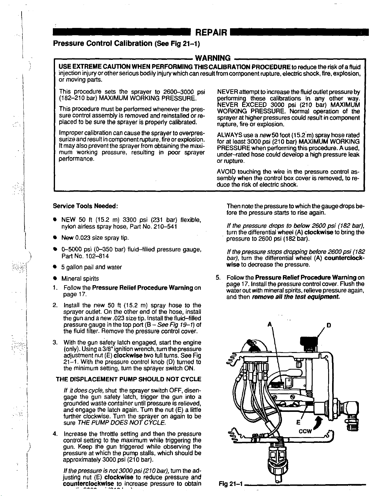
Pressure
Control Calibration
(See
Fig
21-1)
I
I
'I
WARNING
USE EXTREME CAUTION WHEN PERFORMING THISCALIBRATION PROCEDURE
injection injury or other serious bodily injury which can result from component rupture. electric shock. fire, explosion,
or moving parts.
This procedure sets the sprayer to 2600-3000 psi NEVER attempt
(182-210 bar) MAXIMUM WORKING PRESSURE. performing these calibrations
This procedure
sure control assembly is removed and reinstalled or re-
placed to be sure the sprayer is properly calibrated. rupture, tire or explosion.
Service
Tools Needed:
NEW
50
nybn ailless spray hose, Part No. 210-541
New
0.023
must
be performed whenever the pres-
ft
(15.2
m)
size spray tip,
3300
psi (231 bar) flexible,
NEVER EXCEED
WORKING PRESSURE.
sprayer
AVOID touching the wire
sembly when the control box cover
duce the risk of electric shock.
at higher
Then note the pressure to which the gauge drops before the pressure starts to rise again.
If
the pressure drops to
turn the differential wheel (A) clockwise to bring the
pressure to 2600 psi
to
increase the fluid outlet pressure by
3000
pressures
to
reduce the risk of
in
any other way.
psi (210 bar) MAXIMUM
Normal operation of the
could result
in
the pressure control as-
below
(182
bar).
in
is
removed,
2600
afluid
component
to
psi
(182
re-
bar),
C-5ooo
Part No.
5 gallon
Mineral spirits
1.
Follow the Pressure Relief Procedure Warning on
page
2.
Install the new
sprayer outlet. On the other end of the hose, install
the gun and a new .023 size tip. Install the fluid-filled
pressure gauge
the fluid filter. Remove the pressure control cover.
3. With the gun safety latch engaged, start the engine
(onIy).Usinga3/8"ignitionwrench,turnthepressure
adjustment nut (E) clockwise
21-1. With the pressure control knob
the minimum setting, turn the sprayer switch ON.
THE DISPLACEMENT
I
If it does cyde, shut the sprayer switch OFF, disen-
gage the gun safety latch, trigger the gun into a
grounded waste container until pressure is relieved,
and engage the latch again. Turn the nut (E) a little
further clockwise. Turn the sprayer on again
sure
psi (&350 bar) fluid-filled pressure gauge,
102-814
pail
and water
17.
50
ft
(15.2
m)
spray hose to the
in
THE
PUMP
the top port
PUMP SHOULD
DOES NOT
(B
-
See
Fig
19-1)
two
full turns. See Fig
(D)
turned to
NOT CYCLE
CYCLE.
to
of
be
If
the pressure stops dropping before
bar),
turn the differential wheel (A) counterclock-
wise to decrease the pressure.
5.
Follow the Pressure Relief Procedure Warning on
page
17.
Install the pressure control cover. Flush the
water out with mineral spirits, relieve pressure again,
and then
remove
all
the test equipment.
2600
psi
(182
4.
Increase the throttle setting and then the pressure
control setting to the maximum while triggering the
gun. Keep the gun triggered while observing the
pressure at which the pump stalls, which should be
approximately
If
the
pressure
justing nut
counterclockwise to increase pressure
..
""
3000
psi (210 bar).
is
not
3000
psi
(270
bar;), turn the ad-
(E)
clockwise to reduce pressure and
.
,"^.
.
to
obtain
Fig
21-1
Id
Page 22

REPAIR
..
.~ .
Bearing Housing
i%
Connecting
Rod
WARNING
To
reduce the riskof serious bodily injury, including
fluid
injection, splashing fluid in the eyes or on the
skin, or injury from moving parts, always follow the
Pressure Relief Procedure Warning
on page 17
before repairing any part of the sprayer. Disconnect
the spark plug cable.
NOTE:
Steps 1
to
13 refer
to
Fig 22-1.
1. Remove the front cover and screws (23,68),
2. Unscrew the suction tube (30) from the pump, hold-
ing
a
wrench on the pump intake valve
(B)
to
keep the
pump from loosening.
3. Disconnect the pump outlet hose (59) from the dis-
placement pump outlet nipple
4. Use a screwdriver
to
push aside the retaining spring
(87).
(26) at the top of the pump. Push the pin (25) out the
rear.
5. Loosen the jam nut (27) with an adjustable wrench.
Unscrew and remove the displacement pump.
6. Use a hex key wrench
to
remove the four screws (73)
and lockwashers (74) from the bearing housing.
..:.
..
.
..
,..~...
..
.
.?
..
..
.. .
,
..,:
7.
While pulling the connecting rod (22) with one hand,
tap
lightly
with a plastic mallet
ing (20). Pull the bearing housing and the connecting
.
.
rod assembly (22)
8.
Inspect the crank (A) from excessive wear and replace parts as needed.
the lower rear of the bearing housing (21)
to
loosen it from the drive hous-
off
the drive housing.
27’
B*
I
1259
9. Evenly lubricate the inside of the bronze bearing (C)
in the bearing housing (21) and the inside of the connecting rod link (D) with high quality motor oil. Liberally pack the roller bearing
(E)
in the connecting rod
30
assembly (22) with bearing grease.
10.
Assemble the connecting rod (22) and bearing hous-
ing (21).
:,
.
11. Clean the mating surfaces
of
the bearing and drive
housings.
(A)
12. Align the connecting rod with the crank
fully align the locating pins
(20)
with the holes
in
the bearing housing onto
(C)
in the drive housing
the bearing housing (21). Push
the
drive housing
into place with a plastic mallet.
and care-
or
tap
it
Fig
22-1
13. Install the screws (73) and lockwashers (74) on the
to
15
bearing housing and tighten evenly
in-lb
(1.7 Nm).
Page 23

~
\
~
!
.,:
'!
I
I
j
NOTE:
14.
Refer
to
Fig
23-1
for Step
Screw the displacement pump
into the bearing housing
the pin hole in the connecting rod assembly
continue screwing in the pump until the pin slides
easily into the hole. Back
threads of the pump cylinder are flush with the face of
the bearing housing and the outlet nipple
ing back. Push the retaining spring
groove all the way around the connecting rod.
Tighten the locknut
ft-lb
(90
to
100
wrench and a light hammer.
Be sure the retaining spring
groove all the way around,
from working loose due
If the pin works loose, it or other parts could break
due to the force
could be projected through the air.
(27)
N.m) -with a
to
of
the pump action. These parts
14.
about
3/4
of the way
(21).
Hold the pin
off
the pump until the top
(87)
(26)
very tight - about
2-1/4
in. open end
(26)
is firmly in the
to
prevent the pin
vibration.
(25)
(22)
into the
65
(25)
REPAIR
up
to
and
is fac-
to
75
off
TOROUE
.
,
6575
(SO-I00
TO
FT4B
N.Y)
I
,
..,
':.
.:
I
15.
Reinstall the front cover and screw
nect the suction tube
See Fig
22-1.
(30)
and pump outlet hose
(23.68).
Recon-
(59).
Fig
2%
-1
i
Page 24

..
REPAIR
Drive
Housing
WARNING
To reduce the risk of serious bodily injury, including
fluid injection, splashing fluid in the eyes or on the
skin, or injury from moving parts, always follow the
Pressure Relief Procedure
Warning on page 17
NOT allow the gear cluster (1
moving the drive housing
if
dropped. The gear may stay engaged in either the
(20).
drive housing or pinion housing.
8)
to fall when re-
It
is easily damaged
DO
before repairing any part of the sprayer. Discon-
DO
nect the spark plug cable.
NOT lose the thrust balls (20c or 19h) located at
each end
of
the gear cluster, or allow them
to
fall be-
tween gears. The ball, which is heavily covered with
to
NOTE: Refer
1.
Remove the front cover and screws
2. Disconnect the pump outlet hose (59) from the dis-
Fig 24-1 for this procedure.
(23,68).
grease, usually stays in the shaft recesses, but
could be dislodged.
not
removed, the balls will seriously damage the
drive housing.
If
caught between gears and
If
the balls are not in place, the bear-
ings will wear prematurely.
placement pump nipple (57).
two
3. Use a hex key wrench to remove the
and lockwashers
(11)
from the bottom front of the
screws
pinion housing (19m). Then remove the top
.,
.
screws (10) and lockwashers (11).
4. Working from the front of the drive housing, remove
the
two
screws (73) and lockwashers (74).
(1
0)
two
7. Liberally apply bearing grease (20d, supplied) to the
gear cluster (18). Check to be sure the thrust balls
(20c and 19h) are in place.
8.
Place the bronze-colored washer (20a) and then the
silver-colored washer (20b) on the shaft protruding
from the big bearing of the drive housing (20). Align
5.
Lightly tap around the drive housing with a plastic
mallet to loosen it from the pinion housing.
the gears and push the new drive housing straight
onto the pinion housing and locating pins.
..
.:
..,.
.
.
,.
:.
.
..
6.
While holding the connecting rod (22) with one hand,
lightly tap the back of the bearing housing (21) to
loosen the drive housing. Then pull the drive housing
straight
off
the pinion housing.
9. Starling at Step 4 and working backwards, continue
to
reassemble the sprayer. Or, move ahead
next section in this manual
if
further service is
to
the
needed.
Fig
24-1
Page 25

~.
I
:
j
I
I
j
REPAIR’
Pinion, Clutch, Clamp, Field and Engine
Disassembly of these parts can start from the pinion
housing, or from the clutch if no pinion service is needed.
If
starting from the pinion housing,
to 6 of
Drive Housing
If
starting from the clutch,
on page 24, then continue below.
see page
first follow Steps
I
28.
,
Pinion Housing Removal
..,
..
To
reduce the risk of serious bodily injury, including
fluid injection, splashing fluid in the eyes or on the
skin, or injury from moving parts, always follow the
Pressure Relief Procedure Warning
before repairing any part of the sprayer. Disconnect
the spark plug cable.
NOTE:
1.
2.
3.
:.
.:
.:
Refer to Fig
noted.
Remove the
washers
(IO)
ing
Pull
ing. The armature (4a) will come with it.
Pull
27-1) of the pinion housing.
(1
and lockwashers
(1
9m) to the clutch housing (2).
the pinion housing away from the clutch hous-
the armature (48) off the hub (19e - see Fig
25-1
for Steps 1 to
two
bottom screws
1)
first, and then remove the three screws
(1
1)
holding the pinion hous-
on page
3,
except where
(IO)
17
and lock-
..
.
.,
..
..
..
.,
.
Fig
25-1
.-.”
ncn
“C
Page 26
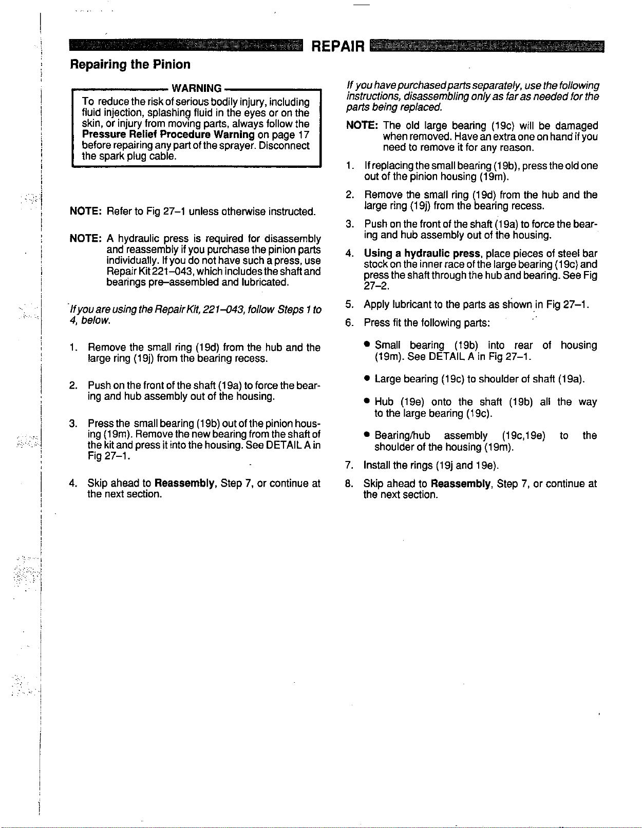
Repairing the Pinion
REPAIR
. .
..
'
.
.,;:
:j
..,
.::,
..
...
.
......
::.
.~ .
L
To
reduce the risk of serious bodily injury, including
!
fluid injection, splashing fluid in the eyes or on the
WARNING
skin, or injury from moving parts, always follow the
i
!
Pressure Relief Procedure Warning
before repairing any part of the sprayer. Disconnect
on page 17
the spark plug cable.
I
i
!
NOTE:
NOTE:
lfyouare
4,
1.
2. Push on the front of the shaft (19a) to force the bear-
3. Press the small bearing
j
Refer to Fig 27-1 unless otherwise instructed.
A hydraulic press is required for disassembly ing and hub assembly out of the housing.
and
individually. If you do not have such a press, use
if
You
purchase
the
pinion parts 4.
Repair Kit221-043, which includesthe shaftand
bearings pre-assembled and lubricated.
using
the
RepairKit,
221-043,
follow Steps 1 to
below.
Remove the small ring
(1
9d) from the hub and the
large ring (19j) from the bearing recess.
ing and hub assembly out of the housing.
(1
9b) out of the pinion hous-
ing
(1
9m). Remove the new bearing from the shaft of
the kit and press it into the housing. See DETAIL
A
Fig 27-1.
in
If
you havepurchasedparts separately, use the
on&
as
far
instructions, disassembling
parts
being replaced.
NOTE:
The old large bearing (19c) will be damaged
as
when removed. Have an extra one on hand
foollowing
needed for the
if
you
need to remove it for any reason.
1.
If replacing the small bearing
(1
9b), press the old one
out of the pinion housing (Ism).
2. Remove the small ring (19d) from the hub and the
large ring (19j) from the bearing recess.
(1
3. Push on the front of the shaft
Using a hydraulic press,
9a) to force the bear-
place pieces of steel bar
stock on the inner race of the large bearing (1 9c) and
press the shaft through the hub and bearing. See Fig
27-2.
5.
Apply lubricant
6.
Press fit the following parts:
to
the parts as shown in Fig 27-1.
Small bearing (19b) into rear of housing
A
(19m). See DETAIL
0
Large bearing (19c) to shoulder of shaft (19a).
in Fig 27-1.
Hub (19e) onto the shaft (19b) all the way
to the large bearing (19c).
Bearing/hub assembly (19c,19e) to the
shoulder of the housing (19m).
7. Install the rings (19j and 19e),
4. Skip ahead to
the next section.
Reassembly,
Step 7, or continue at
8.
Skip ahead to
the next section.
Reassembly,
Step
7,
or continue at
Page 27
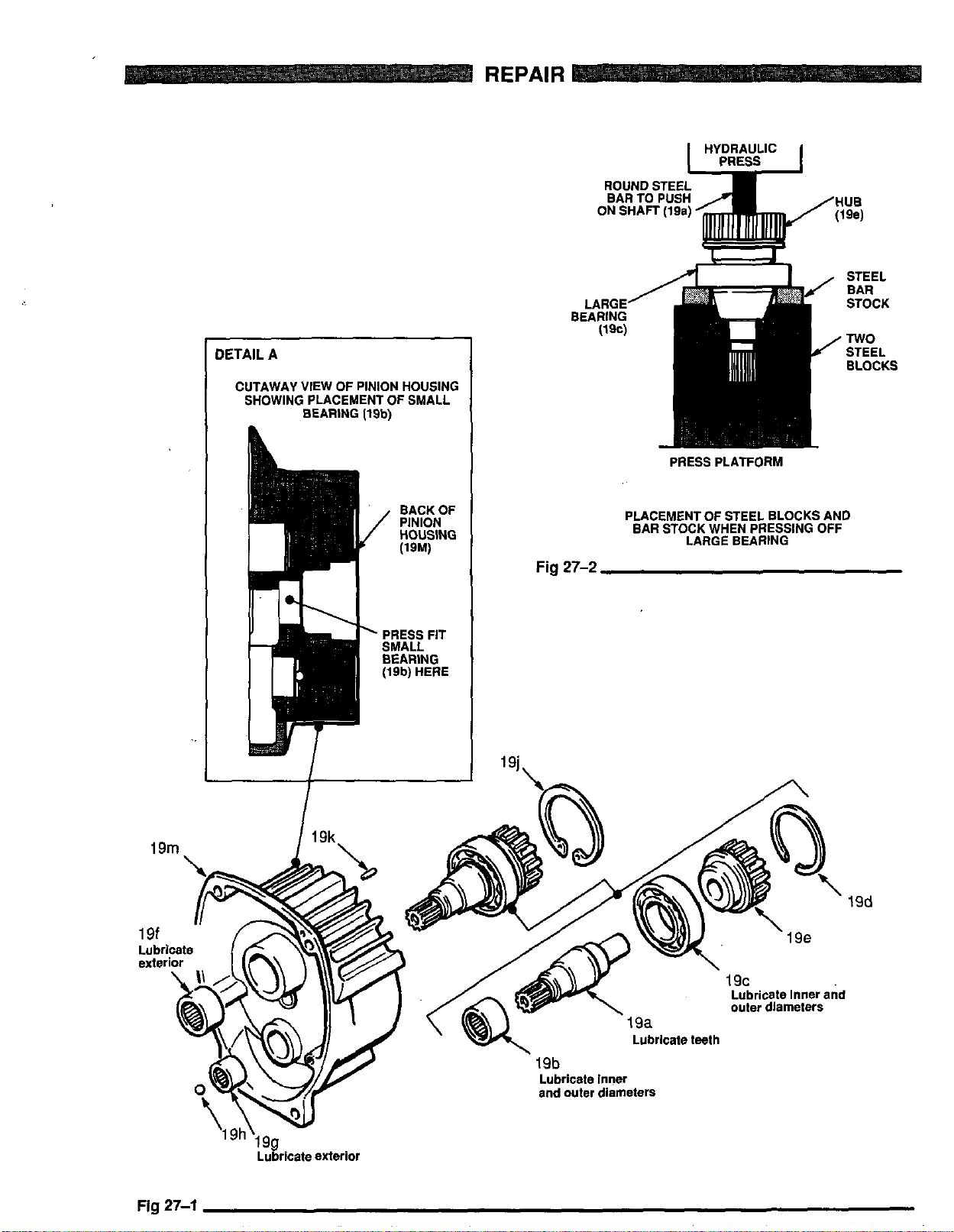
~ ~~
DETAIL
A
CUTAWAY VIEW OF PINION HOUSING
SHOWING PLACEMENT OF SMALL
BEARING
(19b)
REPAIR
ROUND STEE
EAR TO PUSH
PRESS PLATFORM
HUE
(W
19m
BACK OF
PINION
HOUSING
WM)
Fig
27-2
PLACEMENT OF STEEL BLOCKS AND
EAR STOCK WHEN PRESSING OFF
LARGE BEARING
19d
Fig
27-1
Page 28
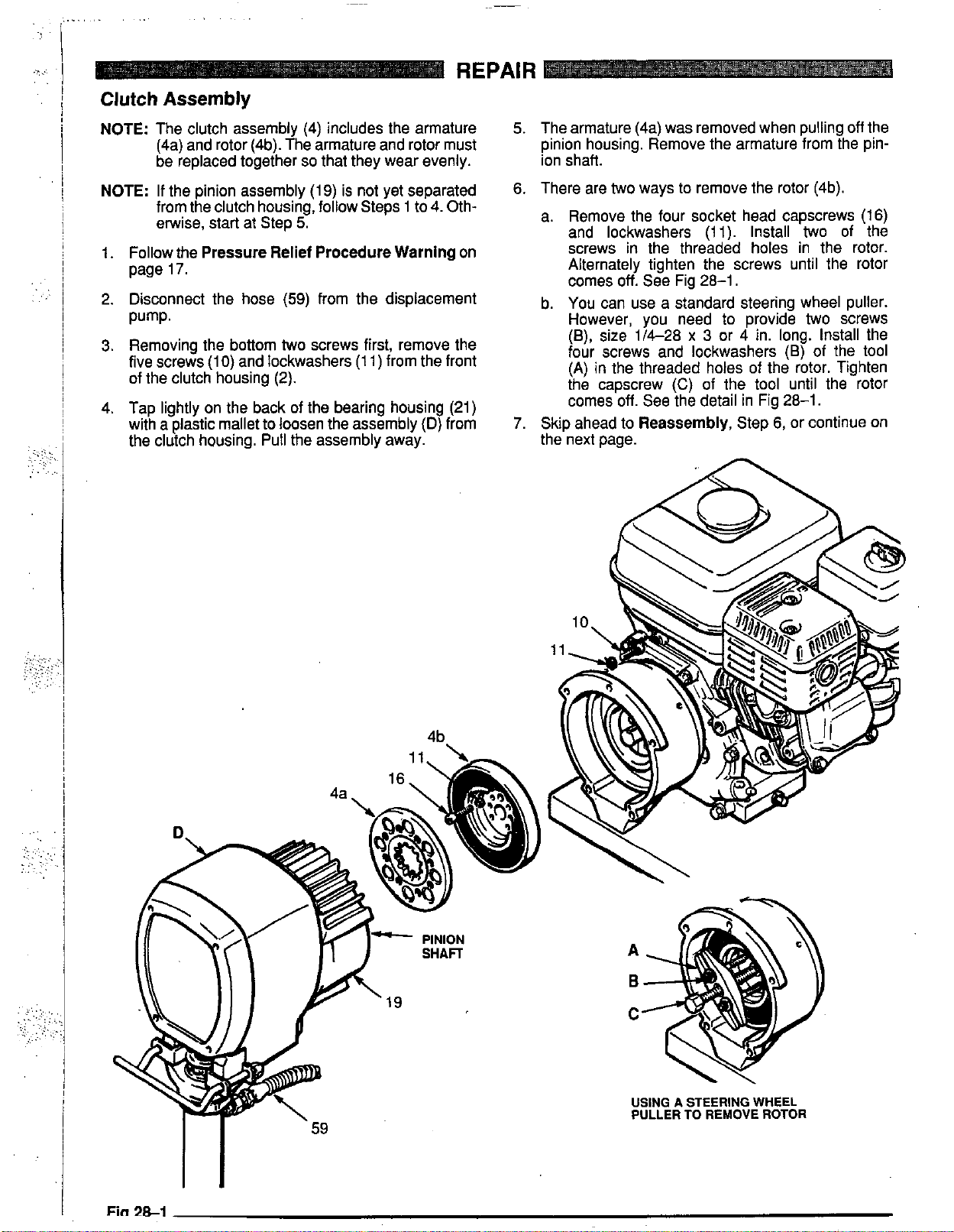
REPAIR
Clutch
NOTE:
NOTE:
1. Follow the
2.
3.
4. Tap lightly on the back of the bearing housing (21)
Assembly
The clutch assembly (4) includes the armature
(4a) and rotor (4b). The armature and rotor must
be replaced together
If the pinion assembly
from the clutch housing, follow Steps 1
etwise, start at Step
Pressure Relief Procedure Warning
page
17.
Disconnect the hose
Pump.
Removing the bottom
five screws
of the clutch housing (2).
with a plastic mallet to loosen the assembly
the clutch housing.
(IO)
and lockwashers
so
that they wear evenly.
(19)
is not yet separated
5.
(59)
from the displacement
two
screws first, remove the
(1
1) from the front
Pull
the assembly away.
to
4. Oth-
(D)
on
from
5.
The armature (4a) was removed when pulling
pinion housing. Remove the armature from the pinion shaft.
6. There are
a. Remove the four socket head capscrews (16)
b. You can use a standard steering wheel puller.
7.
Skip ahead to
the next page.
two
ways to remove the rotor (4b).
and lockwashers (11). Install
screws in the threaded holes in the rotor.
Alternately tighten the screws until the rotor
comes
However, you need
(e),
four screws and lockwashers
(A) in the threaded holes of the rotor. Tighten
the capscrew
comes off. See the detail in Fig 28-1.
off.
See Fig
size 1/4-28 x 3
Reassembly,
(C)
28-1.
of the
to
provide
or 4 in. long. Install the
(6)
tool
until the rotor
Step
6,
or continue
two
two
of
off
of the
screws
the tool
the
on
4b
A
B
c
USING A STEERING WHEEL
PULLER
TO
REMOVE
ROTOR
Fin
28-1
Page 29
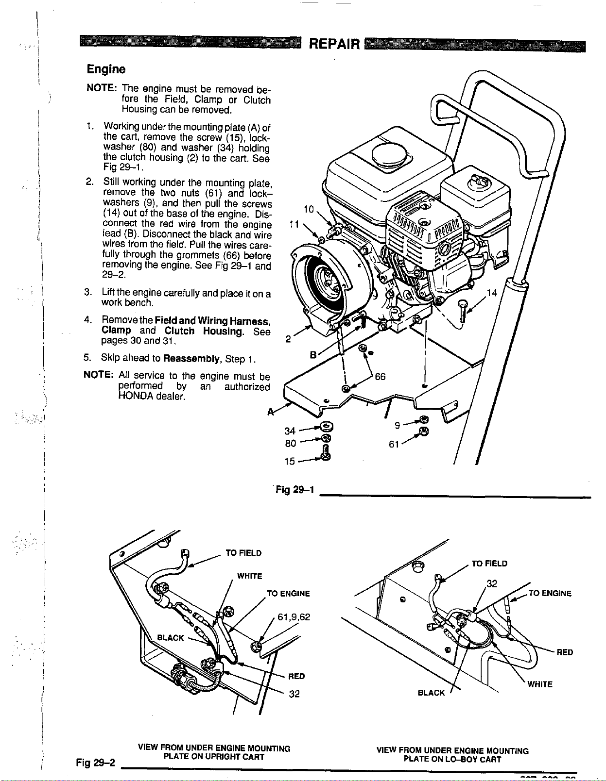
.
..
.
:'
I
I
'!
Engine
NOTE:
1.
2. Still working under the mounting plate,
3. Lift the engine carefully and place it on a
4.
The engine must be removed before the Field, Clamp or Clutch
Housing can be removed.
Working under the mounting plate
the cart, remove the screw (15), lock-
washer
the clutch housing (2) to the cart. See
Fig 29-1.
remove the
washers
(14)
connect the red wire from the engine
lead
wires from the field. Pull the wires carefully through the grommets (66) before
removing the engine. See Fig 29-1 and
29-2.
work bench.
Remove the
Clamp
pages
(80)
and washer (34) holding
two
nuts (61) and lock-
(9),
and then pull the screws
out of the base of the engine. Dis-
(6).
Disconnect the black and wire
Field and Wiring Harness,
and
30
and 31,
Clutch
Housing.
(A)
See
of
REPAIR
5. Skip ahead to
NOTE:
All
service to the engine must be
performed by an- authorized
HONDA
Reassembly,
dealer.
Step 1,
w
Fig
2Sl
VIEW FROM UNDER ENGINE MOUNTING
PLATE ON UPRIGHT CART
!
Fig
29-2
VIEW FROM UNDER ENGINE MOUNTING
PLATE ON LO-BOY CART
"-
-"
^I
Page 30
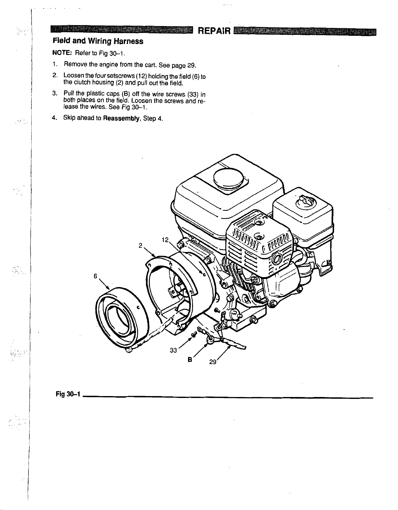
Field and Wiring Harness
REPAIR
.. .
NOTE:
1. Remove the engine from the cart. See page
2.
3.
Refer to Fig 30-1,
Loosen the four Setscrews (1
the clutch housing
Pull
the plastic caps
both places
on
(2)
and pull out the field.
(6)
off
the field. Loosen the screws and re-
29.
2)
holding the field
(6)
the wire screws (33) in
lease the wires. See Fig 30-1,
4.
Skip ahead to
Reassembly,
Step
4.
to
..
..
.,I
..
.. .
..
.:,.
...
..
.
. ..
.,
.
Fig
3&1
6'
29'
Page 31
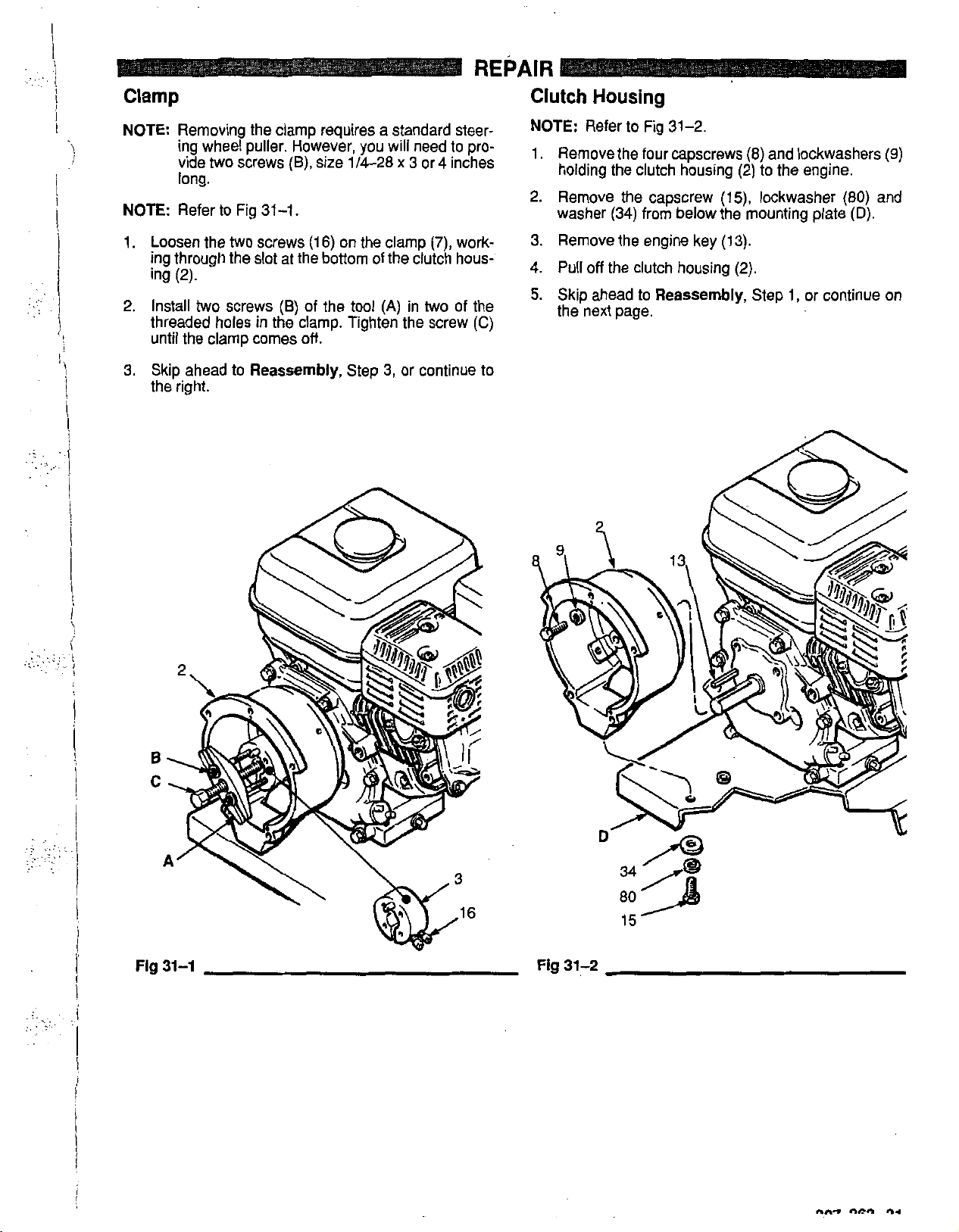
REPAIR
Clamp
NOTE:
NOTE:
1. Loosen the
2.
3.
Removing the clamp requires a standard steer-
ing wheel puller. However,
two
vide
screws
(E),
you
will need to pro-
size 1/4-28 x 3 or 4 inches
long.
Refer to Fig
ing through the slot at the bottom
two
31-1
screws
(1
6)
on the clamp
of
the clutch hous-
ing (2).
Install
two
screws
(E)
of the tool
(A)
in
two
threaded holes in the clamp. Tighten the screw
until the clamp comes
Skip ahead
to
Reassembly,
off.
Step
3,
or continue to
the right.
(7),
work-
of the
(C)
Clutch Housing
NOTE:
1.
2. Remove the capscrew
3.
4.
5.
Refer to Fig 31-2.
Remove the four capscrews (8) and lockwashers
holding the clutch housing (2) to the engine.
(E),
lockwasher (80) and
(34)
washer
Remove the engine key
Pull
off
Skip ahead
from below the mounting plate
(13).
the clutch housing
to
Reassembly,
(2).
Step
1,
or continue
the next page.
(9)
(D).
on
..
.
.,
,
,
. .
.
. ..
..
.
,
.
:.
...
..
..
..
..
.
.
..
..
Fig
31-1
Fig
31-2
Page 32
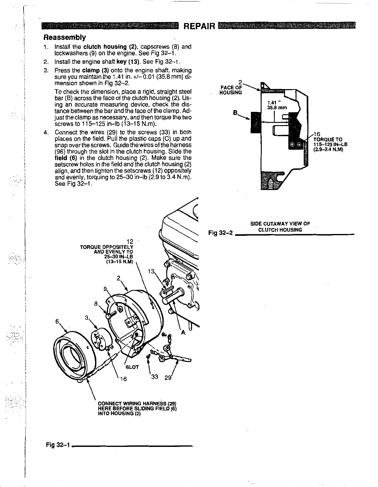
..
..
..:
..
!
i
!
i
1
~
!
!
I
!
!
I
!
.
I
i
~
i
!
1.
Install the
clutch housing (2),
capscrews
(E)
and
lockwashers (9) on the engine. See Fig 32-1.
key
(13).
2. Install the engine shaft
3. Press the
clamp (3)
onto the engine shaft, making
sure you maintain the 1.41 in.
See Fig 32-1.
+/-0.01
(35.8
mm) di-
mension shown in Fig 32-2.
To
check the dimension, place a rigid, straight steel
bar
(B)
across the face of the clutch housing (2).
Us-
ing an accurate measuring device, check the dis-
tance between the bar and the face of the clamp. Ad-
just the clamp as necessary, and then torque the
screws to 115-125 in-lb
(13-15
Nm).
two
4. Connect the wires (29) to the screws (33) in both
places on the field.
Pull
the plastic caps
(C)
up and
snap overthe screws. Guide the wires of the harness
(96) through the slot in the clutch housing. Slide the
field
(6)
in the clutch housing (2). Make sure the
setscrew holes in the field and the clutch housing (2)
align, and then tighten the setscrews (12) oppositely
and evenly, torquing to 25-30 in-lb (2.9 to 3.4 Nm).
See Fig 32-1.
HOUSING
115-125IN-LB
Reassembly
;,<:..::$
. .
.
...
._
SIDE CUTAWAY VIEW
Fig 32-2
.,
.
CLUTCH HOUSING
OF
i
Page 33

REPAIR
5.
Place the
the mounting holes, and carefully guiding the engine assemble the armature to the shaft in the pinion
wire
through the appropriate grommets
ing plate
(14).
clutch housing
washer
plate, connect the engine wire to the red wire and
connect the black and white wires. See Fig
6.
Making sure the face
free of all oil and contaminants, install the rotor,
lockwashers
capscrews to
33-1.
i
engine
(D)
and wiring harness
(E).
lockwashers
(80)
(1)
assembly
Secure the engine with the capscrews
(9)
(2)
with the capscrews
and washer
of
(11)
and capscrews
6.5
to
7.5
and
the
ft-lb
on
the cart, aligning
(29)
from the field, housing
(66)
in the mount-
nuts
(61).
Secure the
(15),
lock- housing using capscrews
(34).
Under the mounting See Fig
33-1.
rotor
(4b)
and the field is
(16).
Torque the
(8.8
to
10
Nm). See Fig
7.
Making sure the face of the
(19)
until the armature contacts the ring
(1
9j).
8.
Assemble the
See Fig
33-1.
Pinion
33-1.
armature (4a)
housing
(1
(19)
0)
and lockwashers
is clean,
to
the clutch
(1
1).
,
.
,:.
..
.
::.i.'.;,.,
.
:,.,::I
.~
.
..
...
i
Fig
33-1
UNDERSIDE
OF
UPRIGHT
CART UNDERSIDE
OF
LO-BOY
CART
307-863
33
Page 34

.;';.,..;
.:~.:.>'.,...
. . ..
. ..
..
,
.. ..
...
.
,.
Page 35
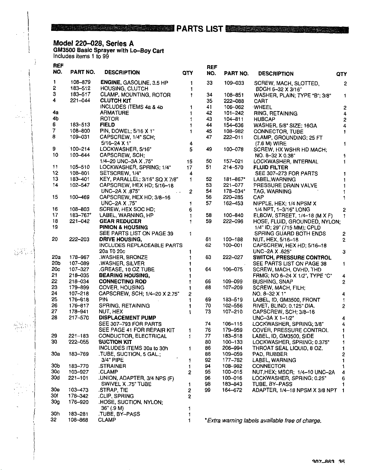
Model
GM3500
Includes
REF
NO.
1
2
3
4
4a
4b
6
7
8
9
10
11
12
13
14
15
16
17
18
19
20
20a
20b
2oc
21
22
i
23
24
25
26
27
28
29
30
30a
30b
30c
30d
30e
30f
309
30h
32
220-028,
Basic
items
Series
Sprayer
1
to
99
with
A
Lo-Boy
PART NO. DESCRIPTION
108-879
183-512
183-517
221-044
183-513
108-800
109431
'100-214
100-644
105-510
108-801
183-401
102-547
100-469
108-803
183-767'
221-042
ENGINE,
HOUSING. CLUTCH
CLAMP,
GASOLINE, 3.5 HP
MOUNTING,
CLUTCH KIT
INCLUDES ITEMS 4a
ARMATURE
ROTOR
FIELD
PIN, DOWEL;
CAPSCREW,
5116-24 x 1"
LOCKWASHER.
CAPSCREW, SCH;
1/420
5/16
1/4"
UNC-3A X .75
LOCKWASHER,
SETSCREW, 1/4'
KEY,
PARALLEL;
CAPSCREW, HEX HD; 5/16-18
UNC-2A X 375
CAPSCREW. HEX HD: 3/8-16
UNC-2A X .75
SCREW, HEX SOC HD;
LABEL. WARNING. HP
GEAR
REDUCER
PINION & HOUSING
SEE PARTS LIST ON PAGE 39
222-203
178-967
107-089
107427
218-035
218-034
179-899
107-218
17-18
176-817
178-941
217-570
221-183
222-055
183-769
183-770
103-927
221-101
1
OM73
178-342
176-920
183-281
108-868
DRIVE HOUSING,
INCLUDESREPLACEABLEPAATS
20a
TO
20c
.WASHER, BRONZE
.WASHER. SILVER
~ ~
.GREASE,
IO
oz
BEARING HOUSING,
CONNECTING ROD
COVER, HOUSING
CAPSCREW, SCH; 1/4-20 X 2.75
PIN
SPRING, RETAINING
NUT, HEX
DISPLACEMENT PUMP
SEE 307-793 FOR PARTS
SEE PAGE 41 FOR REPAIR KIT
CONDUCTOR, ELECTRICAL
SUCTION
INCLUDES ITEMS 30a
.TUBE, SUCTION,
3/4 PIPE
STRAINER
.CLAMP
.UNION, ADAPTER, 3/4 NPS
SWIVEL X .75 TUBE
STRAP. TIE
.CLIP.
.HOSE, SUCTION, NYLON;
36 (.9 M)
.TUBE, BY-PASS
CLAMP
KIT
SPRING
Cart
ROTOR
&
4b
X
1"
SCH;
5/16"
SPRING;
3/16"
~
TUEE
5
sa
~~-
to
GAL.;
1/4
x
30h
718"
(F)
ON
.-
4
5
15
17
A
I
2
1
6
1
1
1
1
1
1
1
1
1
1
2
1
1
1
1
1
1
1
1
2
1
2
2
1
1
1
REF
1
1
1
1
1
1
I
1
NO.
33
34
35
41
42
43
44
45
47
49
50
51
52
53
54
56
57
58
59
61
62
63
64
66
68
69
70
73
74
76
77
80
86
88
92
94
95
96
98
99
PART NO. DESCRIPTION
109433
108-851
222-088
106-082
101-242
104-81
154-636
106-982
222-01
100-078
157-021
214-570
181-867'
221-077
178-034'
220-285
162453
100-840
222-096
100-188
100-001
222-027
106-075
109499
107-209
183-519
102-556
107-21
106-115
179-959
183-518
1
00-1
33
206-994
109-059
177-762
108-962
1
OW1
100-01 6
183-843
164-672
SCREW, MACH, SLOTTED,
BDGH 6-32 X 3/16"
WASHER, PLAIN; TYPE
CART
,WHEEL
RING. RETAINING
1
HUBCAP
WASHER,
CONNECTOR. TUBE
1
CLAMP,
(7.6 M) WIRE
SCREW. HX WSHR HD MACH:
8-32
NO.
LOCKWASHER, INTERNAL
FLUID FILTER
SEE 307-273 FOR PARTS
LABEL,WARNING
PRESSURE DRAIN VALVE
TAG, WARNING
CAP
NIPPLE, HEX: 1/4 NPSM X
1/4 NPT, 1-3/16" LONG
ELBOW. STREET.
HOSE,
1/4"
ID; 29
SPRING GUARD BOTH ENDS
NUT. HEX, 5/16-18
CAPSCREW, HEX HD;
UNC-2A X ,625
SWITCH, PRESSURE CONTROL
SEE PARTS LIST ON PAGE 38
SCREW, MACH, OVHD, THD
FRMG; NO 6-24 X
BUSHING. SNAP
SCREW. MACH. FILH:
NO.
a32
LABEL, ID,
RIVET, BLIND:
0
CAPSCREW,
UNC-3A X 1-1P
LOCKWASHER, SPRING; 3/8"
COVER, PRESSURE CONTROL
LABEL, ID, GM3500. SIDE
LOCKWASHER. SPRING: 0.375
THROAT SEAL'LIQUID,
PAD, RUBBER
LABEL, WARNING
CONNECTOR
5
NUT,HEX; MSCR; 1/4-10 UNG2A 4
LOCKWASHER. SPRING: 0.25 6
TUBE, BY-PASS
ADAPTER,
'Extra warning labels available free
"B";
5/8"
SIZE; 16GA
GROUNDING;
X 0.38"
FLUID, GROUNDED,
(715 MM); CPLD
25
1/4-18
5/16-18
1/2,
TYPE
x
1"
GM3500,
1/4-18
FRONT
0.125"
DIA. 2
SCH; 31a16
6
NPSM X 3/8 NPT
of
charge.
02.
3/8" 1
FT
.
fM X
F)
NY~ON;
~~
"C
QTY
2
2
4
2
4
1
1
1
1
1
1
1
1
1
2
1
2
~
2
3
1
4
2
4
1
4
4
1
1
1
1
2
1
1
1
1
Page 36
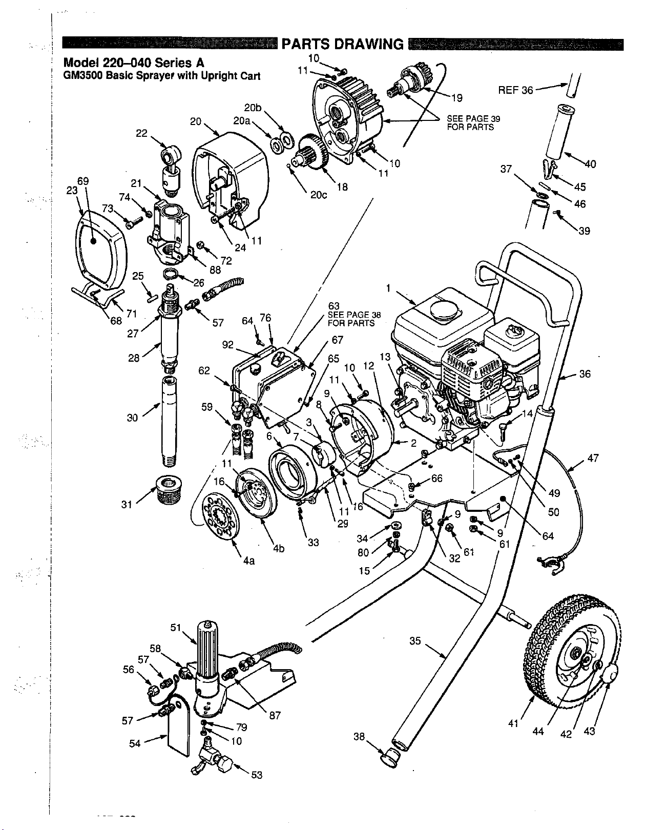
PARTS
DRAWING
.. .
,
..
.. .
..
..
..
...
.
:
..
..
.
..
.
..
Page 37
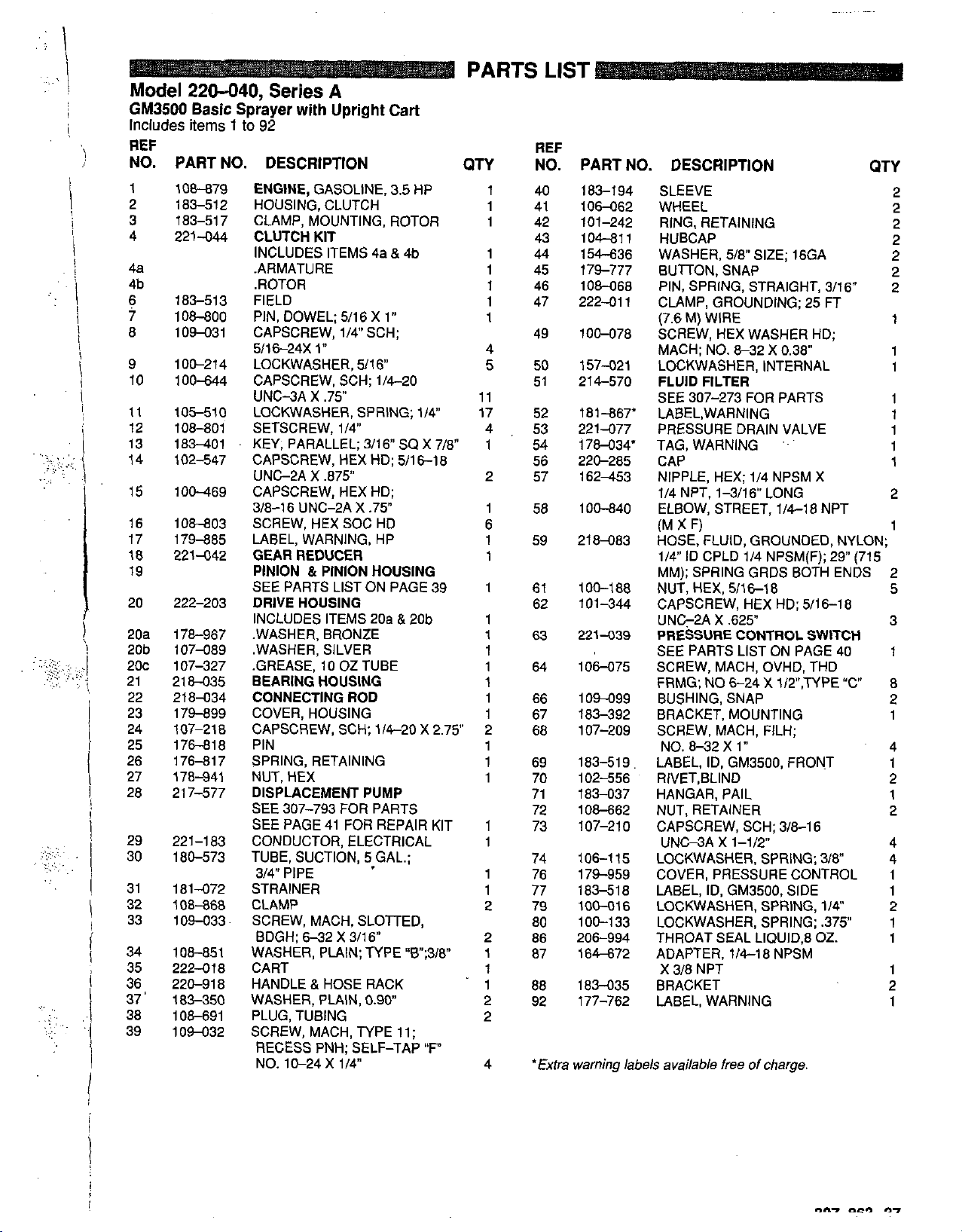
Model
GM3500
Includes
REF
NO.
PART NO. DESCRIPTION QTY NO. PART NO. DESCRIPTION
1
108-879
2
3
4
4a
4b
6
7
8
9
13
14
17
20
ma
20b
2oc
21
22
23
24
25
26
27
28
29
30
31
32
33
34
35
36
37
38
39
10
11
12
15
16
18
19
'
1
83-51
183-51 7
221-044
183-51 3
108-800
1
OM31
100-214
100-644
105-510
108-801
183401
102-547
1
OM69
108-803
179-885
221-042
222-203
178-967
107-089
107-327
218-035
218-034
179-899
107-21
176-818
176-81 7
178-941
21 7-577
221-183
180-573
181-072
108-868
109-033
108-851
222-01
220-91
183-350
108-691
1 OM32
220-040,
Basic
Sprayer
items
1
to
ENGINE.
2
HOUSING,
CLAMP, MOUNTING, ROTOR
CLUTCH
INCLUDES ITEMS 4a & 4b
.ARMATURE
.ROTOR
FIELD
PIN, DOWEL; 5/16 X 1"
CAPSCREW, 1/4" SCH;
5/16-24X
LOCKWASHER, 5/16
CAPSCREW. SCH; 1/4-20
UNC-3A X .75"
LOCKWASHER, SPRING; 1/4
SETSCREW. 1/4
KEY,
CAPSCREW, HEX HD; 5/16-18
UNC2A X ,875"
CAPSCREW, HEX HD;
3/8-16 UNC-2A
SCREW, HEX SOC HD
LABEL, WARNING, HP
GEARREDUCER
PINION & PINION HOUSING
SEE PARTS LIST ON PAGE 39
DRIVE HOUSING
INCLUDES ITEMS 20a & 20b
.WASHER, BRONZE
.WASHER. SILVER
.GREASE,'IO
REARING HOUSING
CONNECTING
COVER, HOUSING
CAPSCREW, SCH; 1/4-20 X 2.75
8
PIN
SPRING, RETAINING
NUT. HEX
DISPLACEMENT PUMP
SEE 307-793
SEE PAGE 41 FOR REPAIR KIT
CONDUCTOR. ELECTRICAL
TUBE,
3/4 PIPE
STRAINER
CLAMP
SCREW, MACH, SLOTTED,
BDGH:
WASHER,
CART
8
8
HANDLE
WASHER, PLAIN,
PLUG. TUBING
SCREW, MACH, TYPE 11;
RECESS PNH; SELF-TAP
NO. 10-24 X 1/4
Series
with
A
Upright
92
GASOLINE. 3.5 HP
CLUTCH
KIT
1
"
PARALLEL; 3/16
oz
~~ ~
ROD
FOR
SUCTION,
6-32
X 3/16
PLAIN;
&
HOSE RACK
~~
X
.75"
TUBE
PARTS
5
GAL.;
TYPE
0.90
Cart
sa
"B;31v
x
"F"
7/8"
PARTS
1 40
1
1
1 44
1
1
1
1
4
5
11
17
4
1
2
1
6
1 59
1
1
1
1
1
1 64
1
1 66
1
2
1
1 69
1
71
1
1
1 76
1 77
2 79
2
1
1
1
2
2
4 'Extra
88
LIST
REF
41
42
43
45
46
47
49
50
51
52
53
54
56
57
58
61
62
63
67
68
70
72
73
74
80
86
87
92
183-1 94
106462
101-242
104-811
154-636
179-777
108-068
222-01 1
100-078
157421
214-570
181-867'
221-077
178434'
220-285
162-453
100-840
218483
100-1
88
101 -344
221-039
106475
104-099
183-392
107-209
183-519.
102-556
183-037
108-662
0
107-21
106-115
179-959
183-51
8
100-016
100-1 33
206-994
164-672
183-035
177-762
warning lab6
QTY
SLEEVE
WHEEL
RING, RETAINING 2
HUBCAP
WASHER,
BUTTON, SNAP
PIN, SPRING, STRAIGHT, 3/16
CLAMP, GROUNDING;
(7.6 M) WIRE
SCREW, HEX WASHER
MACH; NO. 8-32 X 0.38" 1
LOCKWASHER, INTERNAL
FLUID FILTER
SEE
LABEL,WARNING
PRESSURE DRAIN VALVE
TAG, WARNING
CAP
NIPPLE, HEX; 1/4 NPSM X
1/4 NPT. 1-3/16 LONG
ELBOW, STREET, 1/4-18 NPT
(M X F)
HOSE, FLUID, GROUNDED, NYLON;
1/4
MM); SPRING GRDS BOTH ENDS 2
NUT, HEX, 5/16-18
CAPSCREW, HEX HD; 5/16-18
UNC-2A X
PRESSURE
SEE
SCAEW, MACH, OVHD. THD
FRMG; NO
BUSHING, SNAP 2
BRACKET, MOUNTING
SCREW, MACH, FILH;
NO. 8-32 X 1" 4
LABEL.
RIVET,BLIND
HANGAR, PAIL
NUT, RETAINER 2
CAPSCREW, SCH; 3/8-16
UNWA X 1-1/2 4
LOCKWASHER, SPRING; 3/8"
COVER, PRESSURE CONTROL 1
LABEL,
LOCKWASHER. SPRING. 114"
LOCKWASHER;
THROAT SEAL LIQUID.8
ADAPTER, 1/4-18 NPSM
X
3/8 N PT
BRACKET
LABEL, WARNING
?Is
available free of charge.
5/8"
SIZE:
16GA
25
HD;
~~ ~~~
307-273 FOR PARTS
~~ ..
ID
CPLD 1/4 NPSM(F);
,625"
CONTROL
PARTS LIST ON PAGE
~
6-24
ID,
GM3500, FRONT
ID,
GM3500, SIDE
SWITCH
X l/Z',TYPE
SPRING;
OZ.
FT
29
40
"C
,375"
(715
2
2
~
2
2
~
2
2
1
1
1
1
1
1
1
2
1
5
3
1
8
1
1
2
1
4
1
2
1
1
1
2
1
Page 38

PARTS
LIST
Model
GM3500
Includes
REF
NO. PART
101 221-040
102 210-541
103 214-701
104 220-955
231-057
Sprayer with Upright Cart and Hose Kit
items
101
and
104
NO.
DESCRIPTION
BASIC SPRAYER
SEE PARTS ON PAGE 37
HOSE,
GROUNDED, NYLON;
114" ID; CPLD 1/4 NPSM(FBE);
50
FT
(15 M): SPRING GUARDS
BOTH ENDS
HOSE,
3/16 ID; CPLD 1/4 NPSM(F);
3
BOTH ENDS
CONTRACTOR SPRAY GUN:
INCLUDES RAC
GUARD AND
SWITCHTIP 1
GROUNDED, NYLON;
FT
(0.9 M); SPRING GUARDS
IV
DRIPLESS TIP
517
SIZE
102
or
202
,
QTY
1
I
1
Model
GM3500
Includes
REF
NO. PART NO. DESCRIPTION QTY
201 221-028
202 210541
203 214-701
204 220-955
231-077
Sprayer with
items
201
and
BASIC SPRAYER
SEE PARTS ON PAGE 35
HOSE,
1/4" ID; CPLD 1/4 NPSM(FBE);
50
BOTH ENDS
HOSE.
3/16
3
FT
BOTH ENDS
CONTRACTOR SPRAY GUN;
INCLUDES RAC
GUARD AND
SWITCHTIP
Low
Boy
Cart and Hose Kit
204
GROUNDED, NYLON:
FT
(15
M):
SPRING GUARDS
GROUNDED. NYLON:
ID:
CPLD 1/4 NPSM(F);.
(0.9
M);
SPRING GUARDS
IV
DRIPLESS TIP
517
SIZE
1
1
1
1
or
203
Page 39
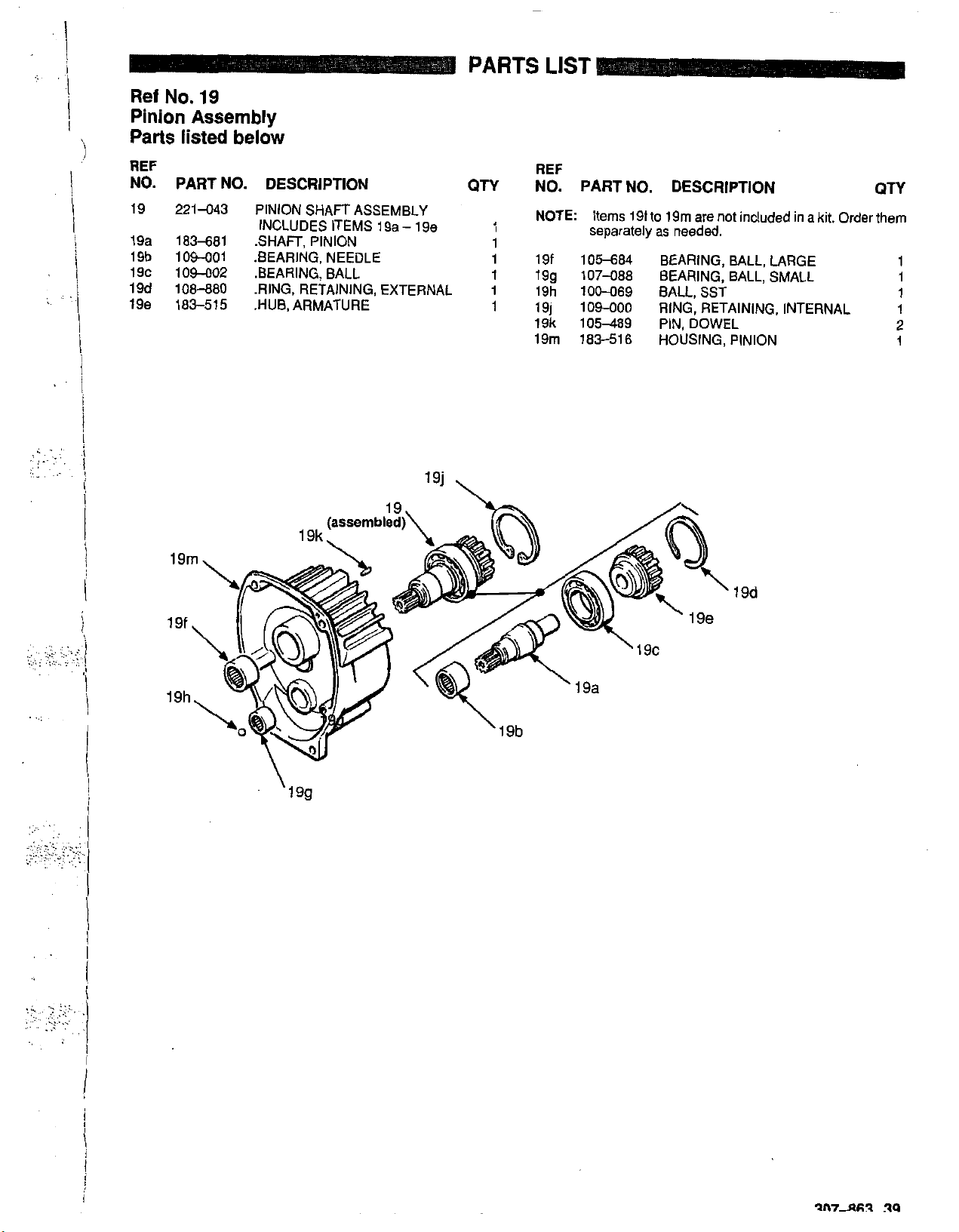
Ref
No.
19
Pinion Assembly
Parts
listed below
PARTS
LIST
I
I
I
. ..
.,
..
..
. .
..
..
..
.
,.
..
REF
NO. PART NO. DESCRIPTION
19 221-043 PINION SHAFT
19a 183-681 .SHAFT
19b
109401
19C 109402 .BEARING, BALL
19d 106-880 .RING. RETAINING, EXTERNAL 1
19e
183-515 .HUB, ARMATURE
INCLUDES ITEMS 19a - 19e
. , .
.BEARING, NEEDLE
~ ~~ ~~
PINION
. .
. . -.
ASSFMRI
.
V
QTY
REF
NO. PART NO. DESCRIPTION
NOTE:
1
1
19f 105-684 BEARING, BALL, LARGE
1
19g
19h 100-069 BALL, SST
1
191 109400 RING, RETAINING, INTERNAL
19k 105-489 PIN, DOWEL
19m 183-516 HOUSING, PINION
Items 19f to 19m are not included in a kit. Order them
separately as needed.
107-088
BEARING, BALL, SMALL
19d
QTY
1
1
1
1
2
1
..
I
i
I
i
i
I
Page 40
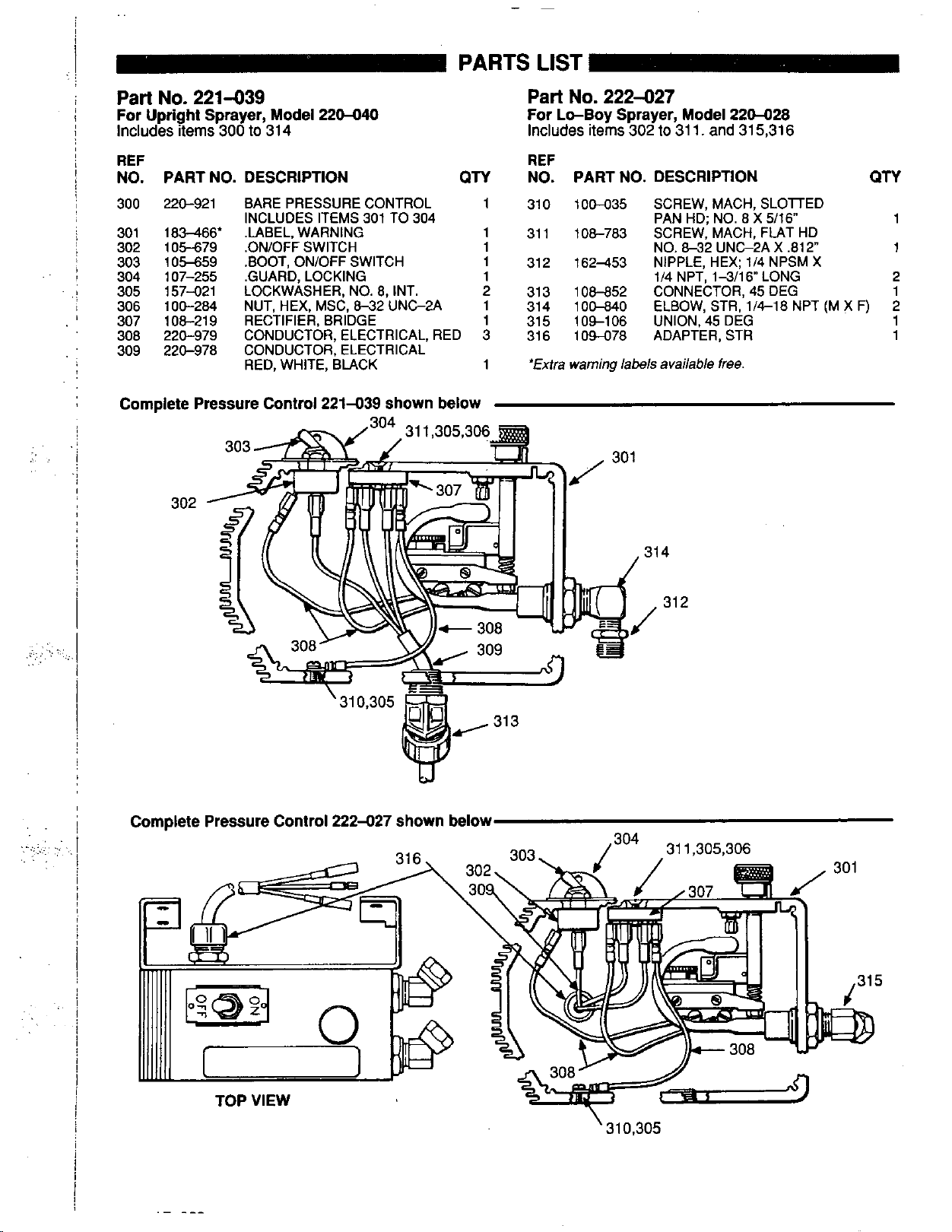
Part
No.
221439
For
Upright Sprayer, Model
Includes items 300 to
314
220440
PARTS
For
LIST
Part
Includes items 302 to 31
-
No.
222-027
Lo-Boy Sprayer, Model
1.
and 315,316
220-028
REF
NO. PART NO. DESCRIPTION
300 220-921 BARE PRESSURE CONTROL
301
302
303
304
305
306
307
308
309
183-466'
105-679
105-659
107-255
157-021
100-284
108-21 9
220-979
220-978
Complete Pressure Control 221-039 shown below
INCLUDES ITEMS 301 TO 304
QTY
REF
NO. PARTNO.
1 310 100-035
31 1 108-783
312 162-453
313 108-852
314 100-840
315 109-106
316 109-078
'Extra
warning labels
DESCRIPTION QTY
SCREW, MACH, SLOlTED
PAN HD: NO.
SCREW,'MACH,
NO.
8-32
NIPPLE. HEX: 1/4 NPSM X
1/4 NPT, 1-3h6" LONG
CONNECTOR, 45 DEG
ELBOW, STR. 1/4-18 NPT (M
UNION, 45 DEG
ADAPTER, STR
available free.
4
8
X 5/16" 1
FLAT
UNG2A X ,812"
HD
X
F)
1
2
1
2
1
1
31 2
.-
TOP VIEW
"_
308
Wd
'310.305
Page 41
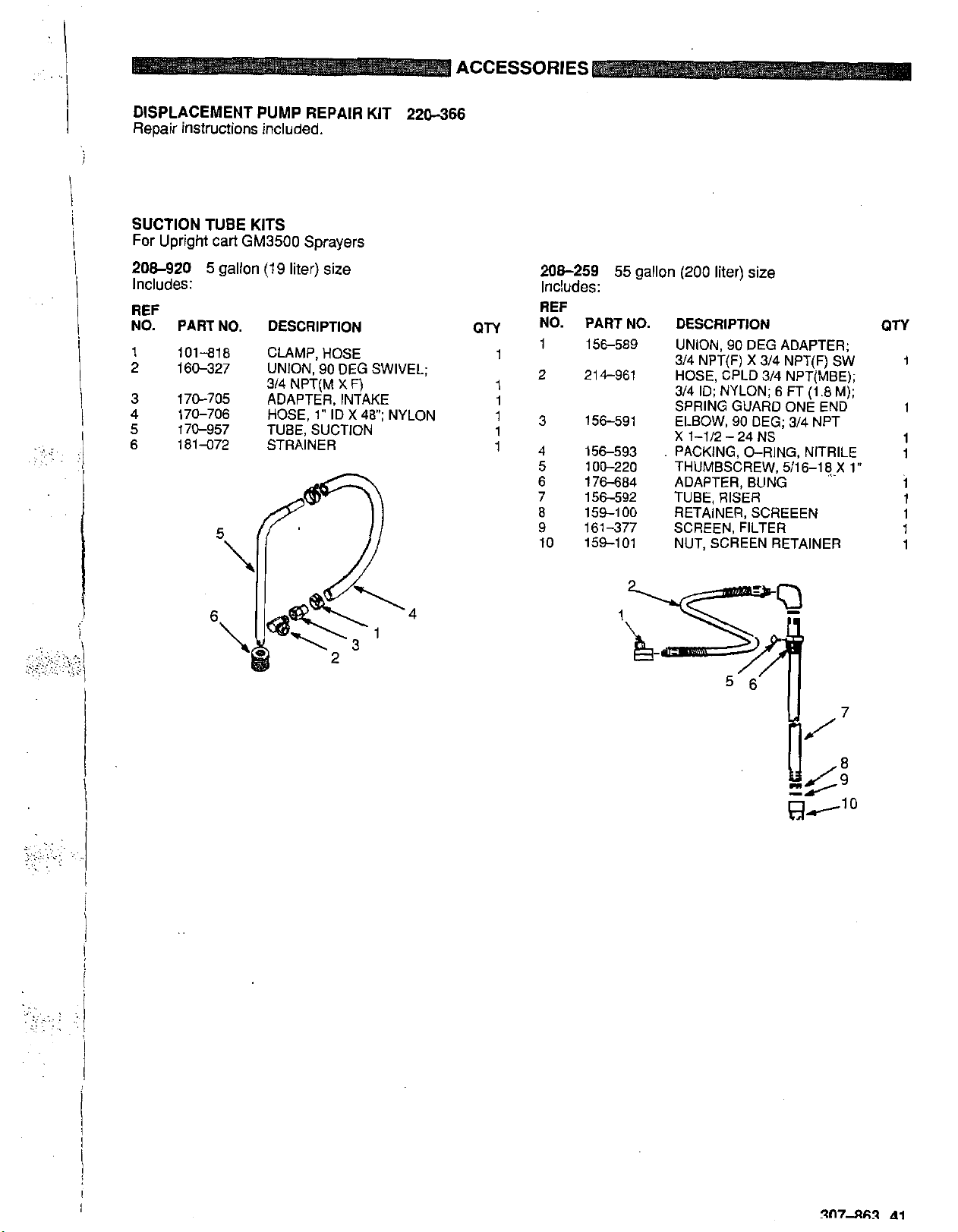
ACCESSORIES
DISPLACEMENT PUMP REPAIR KIT 220366
Repair instructions included.
SUCTION TUBE KITS
For Upright cart
GM3500
Sprayers
206-920
Includes:
REF
NO.
PART NO. DESCRIPTION
101-818
160-327
170-705
170-706
170-957
181472
5
gallon
(19
liter) size
CLAMP, HOSE
UNION, 90 DEG SWIVEL;
3/4
NPT(M
ADAPTER, INTAKE
HOSE,
TUBE, SUCTION
STRAINER
X
F)
1"
ID
X 48"; NYLON
4
208-259
Includes:
REF
QTY
No.
1
1
2
1
1
13
1
14
5
6
7
8
9
10
55
gallon
(200
liter) size
PART NO. DESCRIPTION
156-589
214-961
156-591
156-593
100-220
176-684 ADAPTER, BUNG
156-592 TUBE, RISER
159-100
161-377 SCREEN, FILTER
159-101 NUT, SCREEN RETAINER
UNION, 90
3/4 NPT(F)
HOSE, CPLD 3/4 NPT(MBE);
314
ID;
SPRING GUARD ONE END
ELBOW. 90 DEG:
X
1-1/2 - 24
.
PACKING, O-RING, NITRILE
THUMBSCREW, 5/16-18.X 1"
RETAINER, SCREEEN
DEG
X 314
NYLON; 6
NS
ADAPTER;
NPT(F) SW
FT
(1.8
3/4
NPT
QTY
1
M);
1
1
1
i
1
1
1
1
Page 42
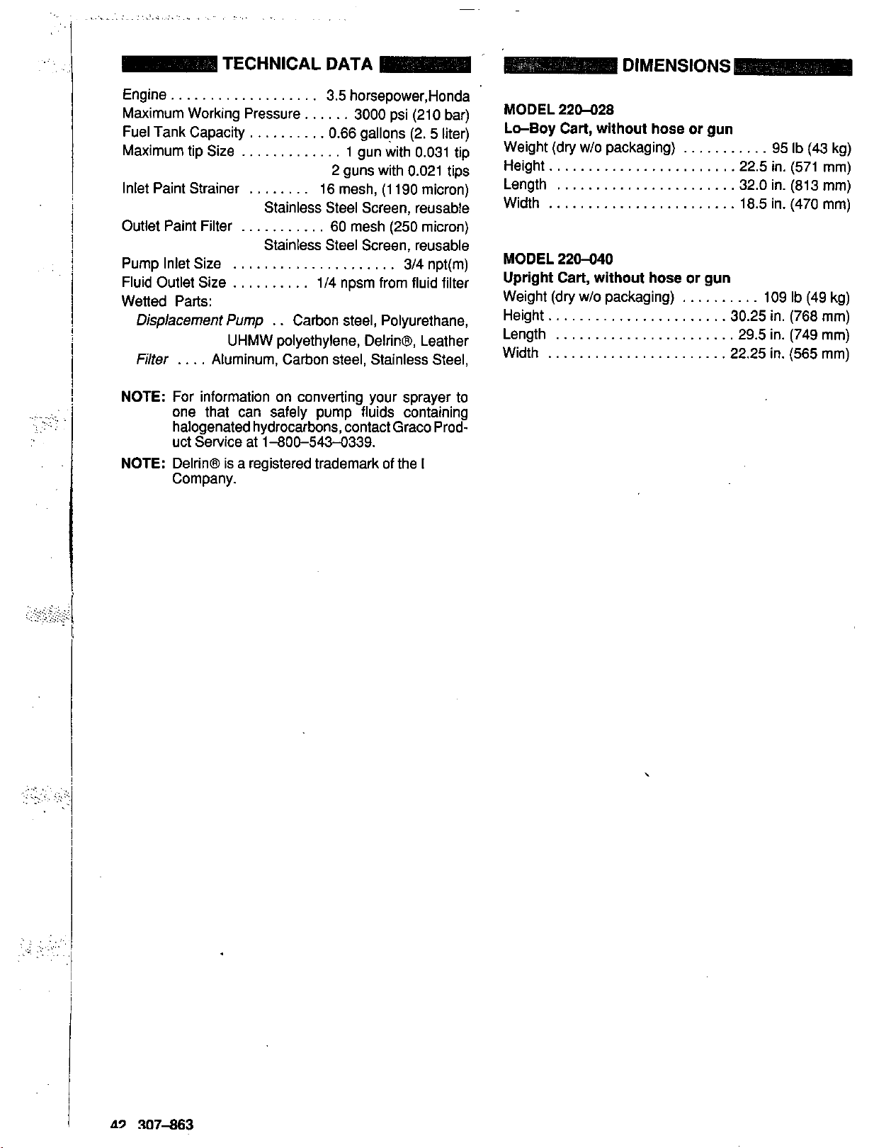
.......
..................
TECHNICAL DATA
.....
..
~
..
...,~
...
...
,;
Engine
Maximum Working Pressure.
Fuel Tank Capacity
Maximum tip Size
Inlet Paint Strainer
Outlet Paint Filter
...................
3.5 horsepower,Honda
.....
..........
.............
........
Stainless Steel Screen, reusable
...........
0.66 gallons (2. 5 liter)
16 mesh,
60 mesh (250 micron)
3000 psi (210 bar)
1
gun with 0.031 tip
2 guns with 0.021 tips
(1
190 micron)
MODEL 220-028
Lo-Boy
Weight (dry
Height.
Length
Width
Cart,
without hose
w/o
packaging)
......................
.......................
........................
or
gun
...........
.22.5 in. (571 mm)
32.0 in. (813 mm)
18.5 in. (470 mm)
95 Ib (43 kg)
Stainless Steel Screen, reusable
Pump Inlet Size
Fluid Outlet Size
Wetted Park
Displacement
Pump
UHMW polyethylene, DelrinB, Leather
Filter
....
Aluminum, Carbon steel, Stainless Steel,
NOTE:
For information on converting your sprayer to
.....................
..........
. .
1/4 npsm from fluid filter
Carbon steel, Polyurethane,
3/4 npt(m)
MODEL 220-040
Upright
Cart,
without hose
Weight (dry w/o packaging)
Height.
Length
Width
......................
.......................
.......................
or
gun
..........
109 Ib (49 kg)
30.25 in. (768 mm)
29.5 in. (749 mm)
22.25
in. (565 mm)
one that can safely pump fluids containing
.
halogenated hydrocarbons, contact Graco Product Service at 1-800-543-0339.
NOTE:
Delrin@ is a registered trademark of the
Company.
.
,
,
.:.:.i
..............
......
.....
.........
....
.,
..
......
.>
.
..
,
.,.
?,.,
..
-
A9
307-863
Page 43

..:
.
..
,
..
'.
:.
.
:.,
.,:.I
I
j
:
',
,
I
I
I
,
..;.,
..
,.
..
..
,...
.
.,
.;::
.,.
.
..
,
..
.::
:i
:,
I
.I
'.
,
I
..
..j
307-863
43
Page 44
WARRANTY
THE GRACO WARRANTY AND DISCLAIMERS
Graco warrants all equipment manufactured by it and bearing its name
to
be free from defects in mate-
rial and workmanship on the date of sale by an authorized Graco distributor to the ori inal purchaser for
use. As purchaser's sole remedy for breach of this warranty, Graco will, for a perio
IY
of twelve months
from the date of sale, repair or replace any pari of the equipment proven defective. This warranty applies
only
when the equipment is installed, operated and mamtained in accordance with Graco's written
recommendations.
This warranty does not cover, and Graco shall not be liable for, any malfunction, damage or wear
caused by faulty installation, misapplication, abrasion, corrosion, inadequate or improper malntenance,
negligence, accident, tampering,
or
substitution of non-Graco component arts Nor shall Graco be
liable for malfunction, damage or wear caused by the incompatibility with C!racoequipment of structures, accessories, equipment or materials not supplied by Graco, or the improper design, manufacture, installation, operation or maintenance of structures, accessories, equipment or materials not supplied by Graco.
This warranty is conditioned upon the prepaid return of the equipment claimed to be defective to an
authorized Graco distributor for verification of the claim. If the claimed defect is verified, Graco will repair or replace free of charge any defective parts. The equipment
If
chasertransportation prepaid.
inspection of the equipment does not disclose any defect in material or
workmanship, repairs will be made at a reasonable charge, which charges may include the costs
will
be returned
to
the original pur-
of
-parts, labor and transportation.
DISCLAIMERS
THE TERMS
ANY OTHER WARRANTIES (EXPRESS
OF
FITNESS FOR A PARTICULAR PURPOSE, AND OF ANY NON-CONTRACTUAL LIABILITIES, INCLUDING PRODUCT
LIABILITIES, BASED ON NEGLIGENCE
CONSEQUENTIAL DAMAGES
ITY
EXCEED THE
BROUGHT WITHIN
AND
LIMITATIONS
OF
THIS WARRANTY CONSTITUTE PURCHASERS SOLE AND EXCLUSIVE REMEDY AND ARE IN LIEU OF
OR
AMOUNT
TWO
(2)
OR
LOSS
OF
THE
YEARS
IMPLIED), INCLUDING WARRANTYOF MERCHANTABILITY
OR
STRICT LIABILITY. EVERY FORM OF LIABILITY FOR DIRECT, SPECIAL
IS
EXPRESSLY EXCLUDED AND DENIED. IN NO CASE SHALL GRACOS LIABIL-
FOR
PURCHASE PRICE. ANY ACTION
OF
THE DATE
OF
SALE.
BREACH OF WARRANTY MUST BE
OR
WARRANTY
OR
EQUIPMENT
GRACO MAKES NO WARRANTY, AND DISCLAIMS ALL IMPLIED WARRANTIES OF MERCHANTABILITY AN0 FITNESS
FOR
A PARTICULAR PURPOSE, WITH RESPECT TO ACCESSORIES, EQUIPMENT, MATERIALS,
SOLD BUT NOT MANUFACTURED BY GRACO.
electric motor, switches, hose, etc.) are subject to the warranty,
NOT
COVERED BY GRACO WARRANTY
These items sold. but
OR
COMPONENTS
not
manufactured bv Graco (such as
if
any, of their manufacturer. Graco will
provide purchaser with reasonable assistance in making any claim for breach of these warranties.
Factory Branches:
Subsidiary and Affiliate Companies:
Atlanta, Dallas, Detroit,
Los
Angeles, West Caldwell
(N.J.)
Canada; England; Switzerland; France; Germany; Hong Kong; Japan
GRACO INC. P.O. BOX 1441 MINNEAPOLIS, MN 55440-1444
PRINTED IN U.S.A.
307463
2-88
 Loading...