

Page 1
INSTRUCTIONS/PARTS LIST
e
507-671
ORACO
Rev
D
SUPERSEDES
A
and
PCN
B
This
manual contains
IMPORTANT
WARNINGS
and
INSTRUCTIONS
READ
AND
RETAIN
FOR
REFERENCE
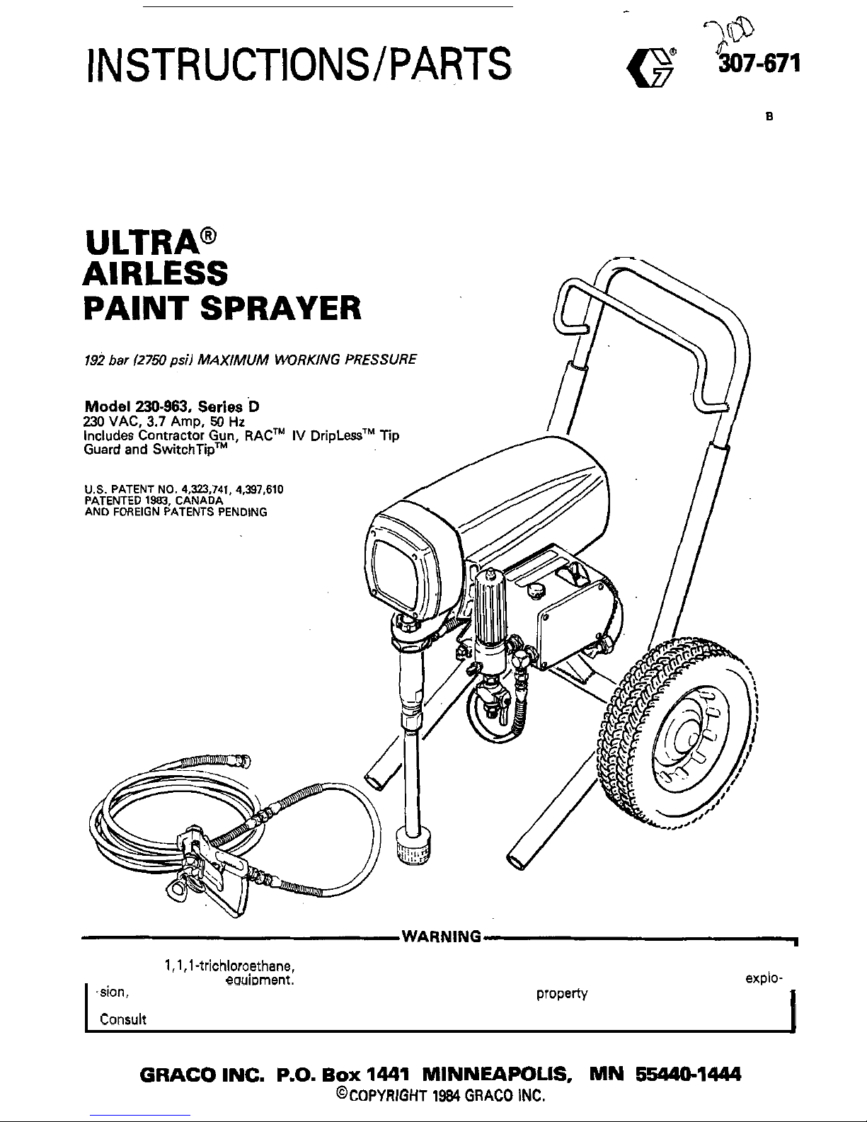
ULTRA@
400
I
Hazard
of
Using Fluids Containing Halogenated Hydrocarbons
such solvents in this
eauimnent. Such use could result in a serious chemical reaction, with the possibility
of
explo-
Never use l,l,l-tnchloroethane, methylene chloride, other halogenated hydrocarbon solvents or fluids containing
I
.sion, which could cause death, serious bodily injury and/or substantial property damage.
Consult your fluid suppliers to ensure that the fluids being used are compatible with aluminum and zinc
parts.
Page 2
INDEX
WARNINGS
..................................................
2
.
3
SETUP
.............................................................
5
INTRODUCTION
................................................
4
OPERATION;
.................................................
6. 7
SHUTDOWN 8 CARE
.........................................
7
TROUBLESHOOTING GUIDE
FLUSHING GUIDELINES
8
.....................................
Motor Won't Operate
...................................
9-11
Low output
..................................................
12
No
Output
...............................................
12. 13
Excessive Pressure Fluctuations
.........................
13
Motor
Is
Hot and Runs Intermittently
..................
13
Electrical Short
......................................
:
.......
14
Spin Test
.....................................................
15
Bridge Test
16
General Repair Notes
...................................... 17
Power Supply Cord Replacement
18
List of Tools
17
Filter Replacement
.........................................
18
ON/OFF Switch Replacement
...........................
19
...................................................
REPAIR SECTION
..................................................
.......................
Microswitch Replacement
................................
19
Bridge Rectifier Replacement
............................
20
Choke Replacement
........................................
21
Varistor Replacement
......................................
21
Pressure Control Replacement
23
Circuit Board Replacement
22
Stall Pressure Calibration
.................................
24
Connecting Rod. Drive Housing or Crankshaft
Replacement
............................................
25. 26
Motor Brush Replacement
................................
27
Motor Capacitor Replacement
...........................
28
Motor Replacement
...................................
29.
30
Sprayer
..................................................
32.
33
Pressure Control
.......................................
34.
35
TECHNICAL DATA Back Cover
How To Order Replacement Parts
33
NOTE:
See manual
307.793.
supplied. for the
displacement pump repair instructions and
parts list
.
...............................
..........................
PARTS LISTS 8 DRAWINGS
......................
...............................
307-671
1
Page 3
HIGH
PRESSURE SPRAY CAN CAUSE EXTREMELY SERIOUS INJURY.
FOR
PROFESSIONAL
USE
ONLY.
OBSERVE
ALL
WARNINGS.
Read
and
understand
all
instruction
manuals,
tags,
and
warnings
before
operating
equipment.
FLUID INJECTION
HAZARD
General Safety
This equipment generates very high fluid pressure. Spray from
the gun, leaks or ruptured components can inject fluid
through your skin and into your body and cause extremely
serious bodily injury, including the need for amputation. Also,
fluid injected or splashed into the eyes or onto the skin can
cause serious damage.
NEVER point the spray gun at anyone or any part of the body.
NEVER put hand or fingers over the spray tip. NEVER try to
“blow back” paint; this is NOT an air spray system.
spraying.
ALWAYS have the
tip
guard in place on the spray gun when
ALWAYS follow the Pressure Relief Procedure. below.
before cleaning or removing the spray tip or servicing any
system equipment.
~.
~~ ~
NEVER try to.stop or deflect leaks
with
your hand or body.
before each use.
Be sure equipment safety devices are operating properly
Medical Alert
-
Airless
Spray
Wounds
If any fluid appears to penetrate your skin, get
EMERGENCY
MEDICAL CARE AT ONCE.
DO
NOT TREAT AS A
SIMPLE CUT.
Tell the doctor exactly what fluid was injected.
jury.
It
Is
important
to
treat the
injury surgically as
soon
Note
to
Physician: injection
in
the skin is a traumatic
in-
as possible.
Do
not delay treatment to research toxiciry.
Toxicity
is
a
concern
with
some exotic coatings injected
directly into the blood stream. Consultation with a plastic
surgeon or reconstructive hand surgeon may be advisable.
Spray Gun Safety
Devices
Be sure
all
gun safety devices are operating properly before
each use. Do not remove or
modify
any part of the gun; this
can cause
a
malfunction and result
in
serious bodily injury.
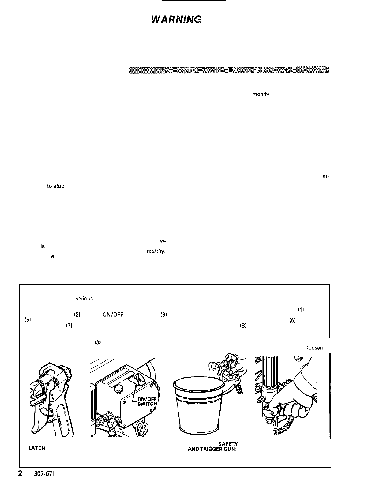
Whenever you stop spraying, even for a moment, always set
Safety
Latch
the gun safety latch in the closed or “safe” position, making
the gun inoperative. Failure to set the safety latch can result
in
accidental triggering of the gun.
The gun diffuser breaks up spray and reduces the risk of fluid
Diffuser
injection when the tip is not installed. Check diffuser operation
regularly. Follow the Pressure Relief Procedure, below,
then remove the spray tip. Aim the gun into
a
metal
pail,
holding the gun firmly to the pail. Using the lowest possible
to an irregular stream, replace
the diffuser immediately.
pressure, trigger the gun. If the fluid emitted is not diffused
in-
Tip
Guard
ALWAYS have the tip guard in place on the spray gun while
spraying. The tip guard alerts you to the fluid injection hazard
and helps reduce, but does not prevent, the risk of accidental
ly placing your fingers or any part of your body close to the
spray tip.
Spray
Tip
Safety
the spray tip clogs while spraying, engage the gun safety latch
Use extreme caution when cleaning or changing spray tips.
If
immediately. ALWAYS follow the Pressure Relief Pro
-
cedure and then remove the spray tip to clean
it.
fully relieved
and the gun safety
latch is engaged.
NEVER wipe
off
build-up around the spray tip
until
pressure is
Pressure
Relief
Procedure
To reduce the risk of serious bodily injury, including fluid injection, injury from splashing fluid or solvent
in
the eyes or on the
skin, moving parts or electric shock, always follow this procedure whenever you shut
off
the sprayer, when checking or servic
-
ing any part of the spray system, when installing, cleaning or changing spray tips, and whenever you stop spraying.
(1
1
Engage
the gun safety latch.
(21
Turn the ON/OFF switch to OFF.
(31
Unplug the power supply cord.
(4)
Disengage the gun safety latch.
gun safety latch.
17)
Open the drain valve, having a container ready to catch the drainage.
181
Leave the drain valve open until
(51
Hold a metal pan
of
the gun firmly to the side of a grounded metal pail, and trigger the gun to relieve pressure.
(61
Engage the
you are ready to spray again.
steps above, VERY SLOWLY loosen the tip guard retaining nut or hose end coupling and relieve pressure gradually, then
loosen
If
you
suspect that the spray
tip
or hose
is
completely clogged, or that pressure has not been
fully
relieved after following the
completely. Now clear the
tip
or hose.
I
~~
ENGAGE SAFETY
TURN
SWITCH
TO OFF
IATCH
UNPLUG
CORD
DISENGAGE SAFETX
ANDTRIGGERQUN:
ENGAGE SAFETY AGAIN
OPEN DRAIN VALVE
I
2
307-671
Page 4

EQUIPMENT MISUSE HAZARD
General Safety
Any misuse of the spray equipment or accessories, such as
overpressurizing, modifying parts, using incompatible
chemicals and fluids, or using
worn or damaged parts, can
cause them to rupture and result
in
fluid injection or other
serious bodily injury, fire, explosion or property damage.
could cause
it
to malfunction.
NEVER alter or modify any part of this equipment; doing
so
CHECK
all
spray equipment regularly and repair or replace
worn or damaged parts immediately.
Read and follow the fluid and solvent manufacturer's literature
regarding the use of protective clothing and equipment.
,
System Pressure
This sprayer can develop
192
bar
(2750
psi) MAXIMUM
WORKING
PRESSURE.
Be sure that all spray equipment and
accessories are rated to withstand the maximum working
pressure
of
this sprayer. DO NOT exceed the maximum work
ing pressure of any component or accessory used in the
system.
Fluid Compatibility
BE SURE that
a11 fluids and solvents used are chemically com
-
patible with the wetted parts shown
in
the Technical Data on
the back cover.
Always read the fluid and solvent manufac
-
turer's literature before using them in this sprayer.
HOSE SAFETY
High pressure fluid
in
the hoses can be very dangerous.' If the
hose develops
a
leak, split or rupture due to any kind of wear,
damage or misuse, the high pressure spray emitted from
it
can
cause a fluid injection injury or other serious bodily injury or
property damage.
ALL FLUID HOSES MUST HAVE SPRING GUARDS ON
kinks or bends at or close to the coupling which can result in
BOTH
ENDS1 The spring guards help protect the hose from
hose rupture.
TIGHTEN all fluid
connections.securely before each use. High
pressure fluid can dislodge
a
loose coupling or allow high
pressure spray to be emitted from the coupling.
tire hose for cuts, leaks, abrasion, bulging cover, or damage or
NEVER use a damaged hose. Before each use, check the
en-
movement of the hose couplings.
If
any of these conditions
exist, replace the hose immediately.
DO
NOT try to recouple
high pressure hose or mend
it
with tape or any other device.
A
repaired hose cannot contain the high pressure fluid.
HANDLE AND ROUTE HOSES CAREFULLY. Do
not
pull on
hoses to
move equipment.
Do
not use fluids or solvents which
are not
comoatible with the inner tube and cover of the hose.
DO NOT expose Graco hose to temperatures above
820C
1180°F) or below -4OOC (-4OOF).
Hose
Grounding
Continuity
Proper hose grounding continuity is essential to maintaining a
grounded spray system. Check the electrical resistance of your
air and
fluid
hoses at least once a week. If your hose does not
have a tag on
it
which specifies the maximum electrical
resistance, contact the hose supplier ormanufacturer for the
maximum resistance limits. Use a resistance meter in the ap
propriate range for your hose to check the resistance. If the
resistance exceeds the
recommended limits, replace
it
im-
your system hazardous. Also read FIRE
OR
EXPLOSION
mediately. An ungrounded or poorly grounded hose can make
HAZARD.
FIRE
OR
EXPLOSION HAZARD
Static electricity is created by the flow of fluid through the
pump and hose.
If
every pan of the spray equipment is not
properly grounded, sparking may occur, and the system may
become hazardous. Sparking
may also occur when plugging
in or unplugging a power supply cord. Sparks can ignite fumes
from solvents and the fluid being sprayed, dust particles and
other flammable substances. whether you are spraying in
doors or outdoors, and can cause a fire or explosion and
serious bodily injury and property damage. Always plug the
sprayer into an outlet at least
6
m
I20
feet) away from the
sprayer and the spray area. Do not plug in or unplug any
power supply cords in the spray area when there is any chance
of igniting fumes still in the air.
If you experience any static sparking or even a slight shock
while using this equipment, STOP SPRAYING IMMEDI
-
ATELY. Check the entire system for proper grounding. Do not
use the system again until the problem has been identified and
corrected.
Grounding
To reduce the risk of static sparking, ground the sprayer and
all other spray equipment used or located
in
the spray area.
structions for your area and type of equipment, BE SURE to
CHECK your local electrical code for detailed grounding
in-
ground all of this spray equipment:
1.
2.
3.
4.
5.
6.
7.
Sprayer: plug the power supply cord, or extension cord,
each equipped with an undamaged three
-
prong plug, into
a properly grounded outlet. Do not use an adapter. All ex
-
tension cords must have three wires and be rated for
15
amps.
Fluid
hoses: use only grounded hoses with a maximum of
500
feet
1150
m) combined hose length to ensure ground
-
ing continuity. Refer to Hose Grounding Continuity.
Spray
gun:
obtain grounding through connection to a
properly grounded fluid hose and sprayer.
Fluid
supply container: according to local code.
Object being
Sprayed: according to local code.
All solvent pails used when flushing, according to local
code. Use only metalpails, which are conductive. Do not
place the pail on a non
-
conductive surface, such aspaper
or cardboard, which interrupts the grounding continuity.
To
maintain grounding continuity when flushing orreliev-
ingpressure, always hold a metal part of the gun firmly to
the side of a grounded metal pail, then trigger the gun.
Flushing Safety
Reduce the risk of fluid injection injury, static sparking, or
splashing by following the specific flushing procedure given
on page
0
of this manual. Follow the Pressure Relief Pro
-
cedure on page
2,
and remove the spray
tip
before flushing.
and use the
lowest possible fluid pressure
during flushing.
Hold a metal
part of the gun
firmly to the
side of
a metal pail
MOVING PARTS HAZARD
Moving parts can pinch or amputate your fingers or other
body parts. KEEP CLEAR of moving parts when starting or
operating the sprayer. Unplug the sprayer, and follow the
Pressure Relief Procedure on page
2
to prevent
it
from star
-
ting accidentally.
IMPORTANT
ticularly the General Standards, Part
1910,
and the Construction Standards, Pan 1926-should be consulted.
United States Government safety standards
have been adopted under the Occupational Safety and Health Act. These
standards-par-
307-671
3
Page 5
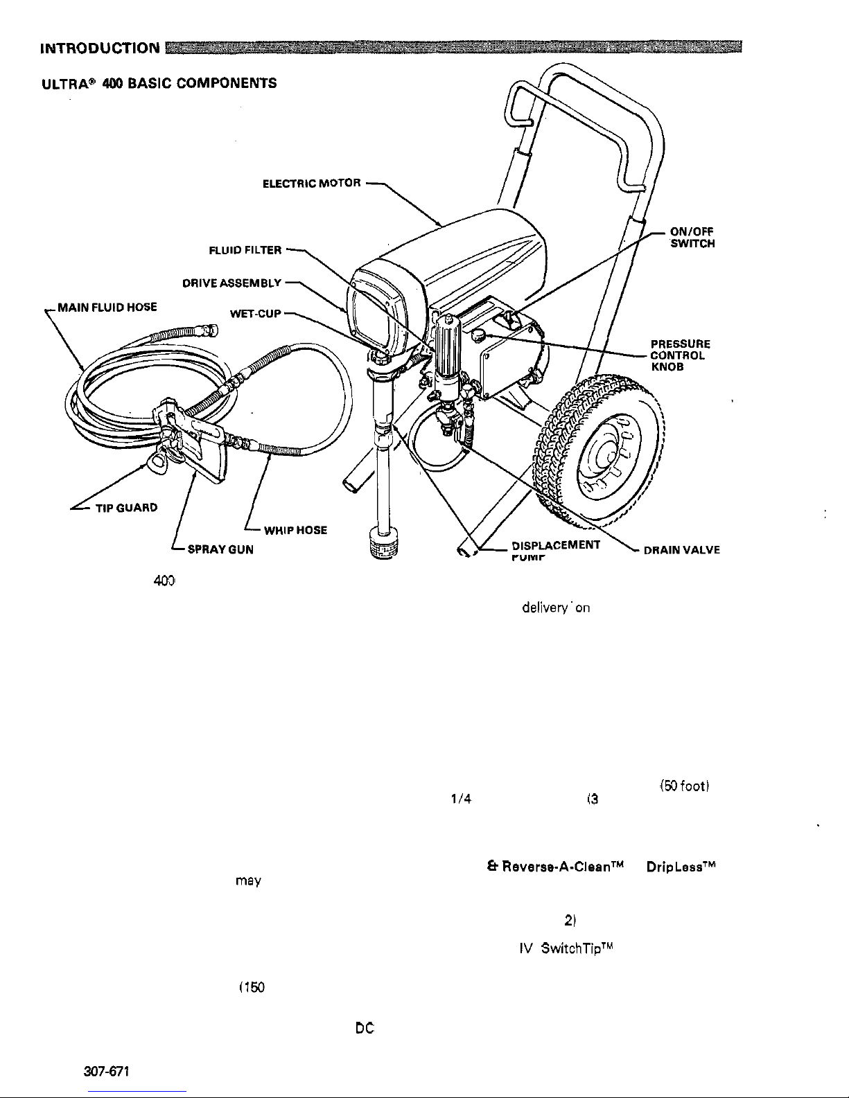
Your new Ultra
"
400
Sprayer functions and operates
differently than other airless paint sprayers. This section
will
help
you
become familiar with the sprayer before
operating
it.
Pressure Control
The pressure control includes an
ONlOFF
switch for the
sprayer, the pressure adjusting control knob, and
a
pressure sensing device.
Its
function is to control the
motor speed
so
that the sprayer maintains constant
fluid pressure
at
the pump outlet.
The DC motor has sealed bearings and replaceable
Motor
motor brushes.
Its
function
is
to drive the displacement
volume
at
the selected pressure.
pump
at
the rate needed to supply sufficient .paint
Working together, the pressure control and motor
cause
the pump to cycle whenever there is fluid or
pressure demand. When the pump is cycling, the motor
sounds like an automobile starter cranking. When the
pump is not cycling, the motor
may hum intermittently
shut itself off. However, there will
still
be power to the
until the fluid pressure stabilizes, then the motor will
sprayer and
it
will stay pressurized and ready to use
unless you manually shut
it
off
and relieve pressure.
Because the motor
is
DC,
it
is less sensitive to low
voltage or voltage fluctuations than an AC motor, and
an extension cord of up to
45
m
(150
feet) can be used.
The sealed drive assembly transfers power from the
DC
Drive Assembly
motor to the displacement pump.
4
307-671
Displacement Pump
The positive displacement, volume
-
balanced pump pro
vides equal fluid delivery'on both the up and down
pump strokes. The pump has a wet-cup which, when
filled with Graco Throat Seal Liquid, helps prevent
damage to the throat packings and piston rod.
Fluid Filter
The fluid filter provides the final paint straining to help
avoid clogs in the hose and spray tip. The filter includes
a
reusable element and a drain valve for relieving fluid
pressure when shutting
off
the sprayer.
Two grounded, nylon spray hoses with spring guards
Hoses
are included with the sprayer. The
15.2
m (50foot) hose
hose allows flexible gun movement. The nylon hose
has
a
114
in. ID. The
0.9
m
(3
foot),
3/16
in. ID whip
material acts
as a
pulsation dampener to absorb
pressure fluctuations.
Spray Gun
&
Reverse-A-CleanTM IV DripLessTM Tip
The spray gun includes
a
trigger safety latch which
Guard
prevents accidental triggering when
it
is engaged (see
the WARNING on page
2)
and a trigger guard which
prevents accidental triggering if the gun is dropped. The
Reverse
-A-
Clean
IV
SwitchTipTM uses high pressure
fluid to remove clogs from the spray tip without remov
-
ing
it
from the gun.
It
includes a safety tip guard which
helps reduce the risk of fluid injection injury.
Page 6

SETUP
1.
Connect
Hose
and Gun (Refer
to
Fig
1.)
NOTE:
When tightening fittings at the pressure control, hold one wrench firmly on the hex of
the pressure control fitting
to
keep
it
from
rotating. Use another wrench
to
tighten the
mating fitting.
a. Remove the plastic cap plug from the filter
outlet nipple and tightly screw the
15.2
m
(50
ft)
fluid hose onto the nipple.
b. Tightly connect the whip hose between the
c. Don't use thread sealant on swivel couplings.
The sealant can prevent the swivel from
rotating freely.
fluid hose and the gun inlet connection.
d. Don't install the spray tip
yet1
IcAUTioNl
To avoid damaging the pressure control, which
may result in poor equipment performance and
component damage, follow these precautlons:
1.
2.
3.
4.
Always use nylon spray hose
at
least
15.2
m
(50
ft)
long.
to act
as a pulsation dampener.
Never use a wire braid hose as it
is
too rigid
Never install any shutoff device between
the filter and the main hose. See
Flg
1.
Always use the main filter outlet for one-
gun operation. Never plug this outlet.
~~
2.
Fill Packing Nutiwet-Cup
(See
Fig
2.)
Throat Seal Liquid (TSL), supplied.
Fill
the packing nut/wet-cup
1/3
full with Graco
3.
Check Electrical Service
a.
Be
sure the electrical service is properly rated
for your sprayer and that the outlet you use
Is
properly grounded.
b. Attach an appropriate plug to the power supply
cord, according
to
your local electrical codes.
c. Use an extension cord which has
3
wires of
a
minimum
12
gauge size, and a maximum of
45
m
(150
ft)
long. Longer lengths may affect
sprayer performance.
4.
Plug
in
the Sprayer
a.
Be sure the ONlOFF switch
is
OFF. 'Refer
to
Fig
3.
Then plug the cord into a grounded elec
-
trical outlet
at
least 6 m
(20
ft)
away from the
spray area.
WARNING
Proper electrical grounding is essential
to
reduce
the risk of fire or explosion which can result in
serious
bodily.injury and property damage. Refer
to the warning section
FIRE
OR
EXPLOSION
HAZARD
on page 3 for more detailed grounding
instructlons.
5.
Flush the pump to remove the lightweight oil
which was left in to protect pump parts after fac-
tory
testing.
a. Before using water-base paint, flush with
mineral spirits followed by soapy water, and
then
a
clean water flush.
b. Before using oil
-
base painr, flush with mineral
c.
See
"
Flushing Guidalines" on page 8 for
6.
Prepare the paint according
to
the manufacturer's
recommendations.
a.
Remove any skin that may have formed.
b.
Stir the paint
to
dissolve hard pigments.
c. Strain the paint through
5
fine nylon mesh
bag
ticks that could clog the filter or spray tip. This
(available
at
most paint dealers)
to
remove par-
is probably the
mosr
importanr step toward
trouble-free spray painting,
307-671
6
spirits only.
flushing procedure.
~ ~~
Page 7
OPERATION
WARNING
Pressure Relief Procedure
To reduce the risk of serious bodily injury, in
cluding fluid injection, injury from splashing fluid
or solvent in the eyes or on the skin, moving parts
whenever you shut
off
the sprayer, when check-
or electric shock, always follow this procedure
when installing, cleaning or changing spray tips,
ing or servicing any part of the spray system,
and whenever you stop spraying.
1.
Engage the gun safety latch.
2.
Turn the ON/OFF switch to OFF.
3.
Unplug the power supply cord.
4.
Disengage the gun safety latch.
5.
Hold a metal part of the gun firmly to the
side of a grounded metal pail, and trigger
the gun to relieve pressure.
6.
Engage the gun safety latch.
7.
Open the filter drain valve, having a con-
8.
Leave the drain valve open until you are
tainer ready to catch the drainage.
ready to operate the sprayer again.
a.
Close the filter drain valve.
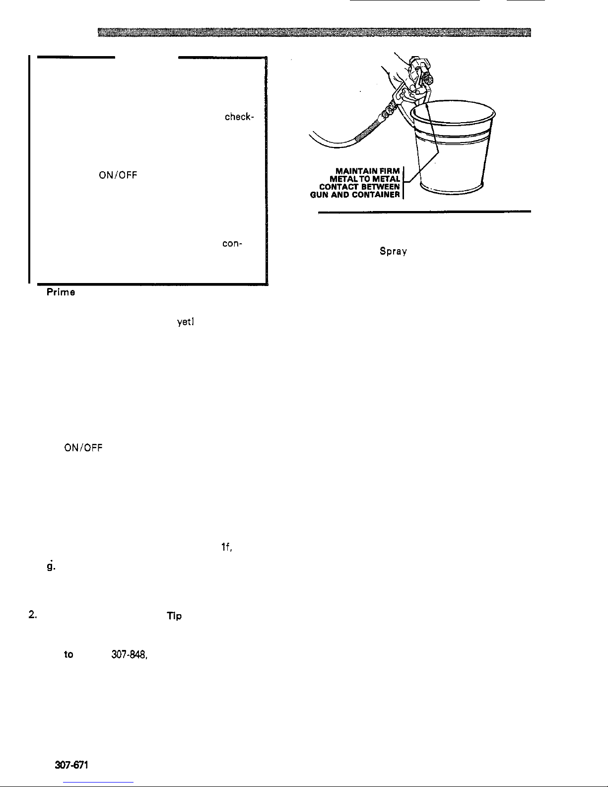
Prime the Sprayer
with
Paint.
b. Don't install the spray tip
yet1
c. Put the suction tube into the paint container.
d. Turn the pressure adjusting knob all the way
counterclockwise to the lowest pressure set
-
ting.
e.
Disengage the gun safety latch.
f. Hold
a
metal part of the gun firmly against and
aimed into
a
metal waste container.. See Fig
4.
ON/OFF switch to ON, and slowly increase the
Squeeze the trigger and hold
it
open, turn the
the gun triggered until
all
air is forced out of the
pressure setting until the sprayer starts. Keep
system and the paint flows freely from the gun.
Release the trigger and engage the safety.
NOTE: If the pump
is
hard to prime, place a container under the drain valve and open the
drain valve. When fluid comes from the
valve, close
it.
Then disengage the gun
safety and proceed
as
in Step If, above.
4.
Check
all
fluid connections for leaks. If any are
found, follow the Pressure Relief Procedure
Warning, above, before tightening connec
-
tions.
2.
Install the Spray Tip and
Tip
Guard
a.
Be
sure the gun safety latch
is
engaged.
b. Install the spray tip. If using the RAC
IV,
refer
to manual
307-848,
supplied with the gun, for
installation instructions.
Fig
4
3.
Adjusting the Spray Pattern
a.
Increase the pressure adjusting knob setting
just until spray from the gun
is
completely
fogging, and to decrease tip wear and extend
atomized.
To
avoid excessive overspray and
the life of the sprayer, always use the lowest
possible pressure needed to get the desired
results.
b. If more coverage is needed, use
a
larger tip
rather than increasing the pressure.
c. Test the spray pattern.
To
adjust the direction
of the spray pattern, engage the gun safety and
loosen the retaining nut. Position the tip guard
for
a
vertical pattern. Then tighten the retaining
horizontally for
a
horizontal pattern or vertically
nut.
6
307-671
Page 8
4.
Cleaning a Clogged Tip
WARNING
To avoid
a
fluid injection injury,
DO
NOT hold
your hand, body, or
a
rag in front of the spray tip
when cleaning or checking
a
clogged tip. Always
point the gun toward
.the ground or into a waste
container when checking to see if the
tup
I
S
clear.
DO
NOT try to "blow back" paint; this is NOT an
air spray sprayer.
a. Clean the front of the tip frequently during the
day's operation.
First,
follow the Pressure
Relief Procedure Warning on page
6.
Then
use a solvent-soaked brush to keep fluid from
building up and clogging the tip.
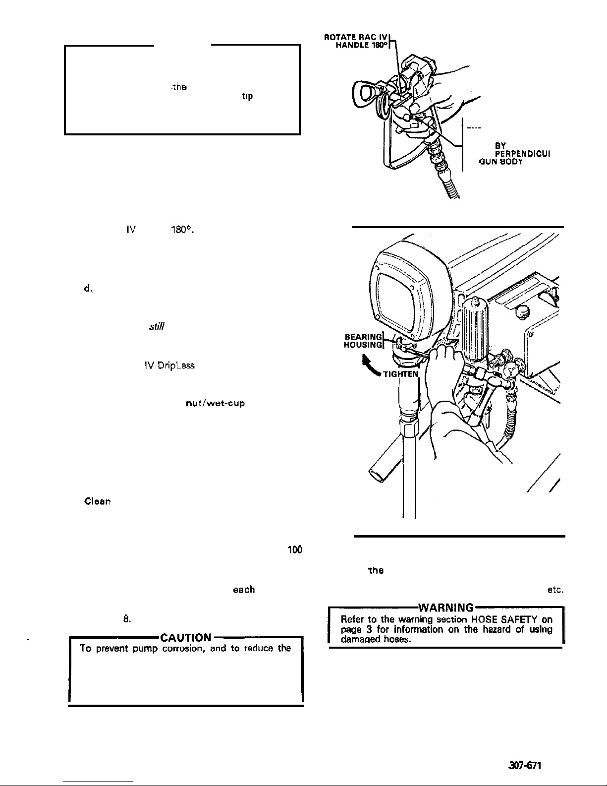
b. If the spray tip does clog, release the gun trig-
ger, engage the gun safety, and rotate the
RAC
IV
handle
180°.
See Fig
5.
c. Disengage the gun safety and trigger the gun
into
a
waste container. Engage the gun safety
again.
d., Return the handle to the original position,
disengage the gun safety, and resume spraying.
e.
if
the tip is stili dogged,
engage the gun safety,
shutoff and unplug the sprayer, and open the
drain valve to relieve pressure. Clean the spray
tip as shown in manual
307-848,
supplied with
the RAC
IV
DripLess tip guard.
SHUTDOWN
AND
CARE
1.
Check the packing nutlwet-cup daily. First
follow the Pressure Relief Procedure Warning
on page
6.
Be sure the wet-cup is
113
full of TSL
at
all
times to help prevent fluid buildup on the piston
rod and premature wear of packings. The packing
nut should be tight enough to stop leakage, but no
tighter. Overtightening may cause binding and
ex
-
cessive packing wear.
Use
a
screwdriver and light
hammer to adjust the nut. See Fig
6.
2.
Clean the fluid filter often and whenever the
sprayer is stored. First follow the Pressure Relief
Procedure Warning on page
6.
Refer to manual
307-273,
supplied, for the cleaning procedure.
3.
Lubricate the bearing housing after every
100
hours of operation. Fill the cavity
of
the bearing
housing with SAE
10
nondetergent oil.
4.
Flush the sprayer at the end
of
each work day
and fill
it
with mineral spirits to help prevent pump
corrosion and freezing.
See
"
Flushing Guidelines
"
on page
0.
chance of fluid freezing in the pump or pressure
type of paint in the sprayer when it is not in use.
control in cold weather, never leave water or any
result in loss of pressure or stalling.
Freezing can seriously damage the sprayer and
TRIGGER SAFETY
ENGAGETHE
LATCH
BY
TURNING
LATCH
PERPENDICUI
TO
QUN
BODY
AR
Fig
5
Fig
6
6.
Coil the hose and hang
it
on the hose rack when
storing
it,
even for overnight, to help protect the
hose from kinking, abrasion, coupling damage,
etc.
rWARNiNG1
Refer to the warning section
HOSE
SAFETY on
page
3
for information on the hazard of using
damaged hoses.
5.
For vary short shutoff periods, leave the suction
tube in the paint, follow the Pressure Relief Procedure Warning on page
6,
and clean the spray
tip.
307-671
7
Page 9
FLUSHING
GUIDELINES
When to Flush
1.
New Sprayer. Your new UltraQ
400
Sprayer was
factory tested in lightweight motor'oil which was
5.
Storage.
left
in to protect pump parts. spirits and leave the pump, hose and gun filled with
Water
-
base paint: flush with water, then mineral
Before using water-base paint, flush with mineral
spirits, followed by soapy water, and then
a
clean
mineral spirits. Shutoff and unplug the sprayer,
open the drain valve to relieve pressure and leave
water flush.
Before using oil
-
base pain!, flush with mineral
open.
spirits only. and unplug the sprayer, open the drain valve to
Oil-base paint: flush with mineral spirits. Shutoff
2.
Changing Colors. Flush with*a compatible solvent
relieve pressure and leave open.
such as mineral spirits or water.
6.
Startup after storage.
3.
Changing from water-base
to
oil-base paint.
Before using water
-
base paint, flush out mineral
Flush with soapy water, then
minera1,spirits.
spirits with soapy water and then a clean water
flush.
4.
Changing from oil-base to water-base paint.
Flush with mineral spirits, followed by soapy water, spirits with the fluid to be sprayed and the sprayer is
When using oil
-
base paint, flush out the mineral
then
a
clean water flush. ready to use.
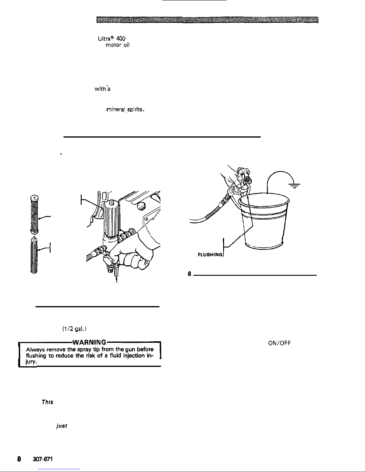
How to Flush
1.
Follow the Pressure Relief Procedure Warning
on page
6.
'
2.
Remove the filter bowl and screen; see manual
307-273
supplied. Clean the screen separately and
install the bowl without the screen.
FILTER
BOWL
SCREEN
MAINTAIN FIRM
METAL TO METAL
CONTACT WHEN
FILTER
SUPPORT
Fig
8
4
DRAIN VALVE
SHOWN OPEN
Fig
7
3.
Close the filter drain valve.
4.
Pour 2 liters
(112
gal.) of compatible solvent into a
bare metal pail. Put the suction tube in the pail.
Always remove the spray tip from the gun before
flushing to reduce the risk of a fluid injection in-
IWARNING1
5.
Disengage the gun safety latch.
6.
Point the spray gun into a grounded metal waste
container and with a metal part of the gun firmly
touching the metal container, squeeze the gun trig-
ger.
This procedure helps avoid static sparking
which can cause fire or explosion and splashing.
With the gun triggered, turn the ONIOFF switch to
clockwise
just
until
the sprayer starts. Keep the
ON
and slowly
turn
the pressure adjusting knob
gun triggered until clean solvent comes from the
nozzle. Release the trigger and engage the gun
safety latch.
7.
Check
all
fluid connections for leaks. If any leak,
follow the Pressure Relief Procedure Warning
on page
6.
Now tighten the connections, start the
sprayer, and recheck the connections for leaks.
8.
Remove the suction tube from the pail. Disengage
the gun safety and trigger the gun to force solvent
from the hose.
Do
not let the pump
run
dry for
more than
30
seconds to avoid damaging the
pressure control. Then turn ON/OFF switch
to
OFF and engage the gun safety latch.
9.
Unplug the power supply cord. Open the drain
valve and leave open until you
are
ready to use the
the clean screen. Reinstall the bowl, hand tight
sprayer again. Unscrew the filter bowl and reinstall
only.
10.
If
you have flushed with mineral spirits and are going to use a water-base paint, flush with soapy
water followed by
a
clean water flush. Then repeat
Step
1.
8
307-671
Page 10
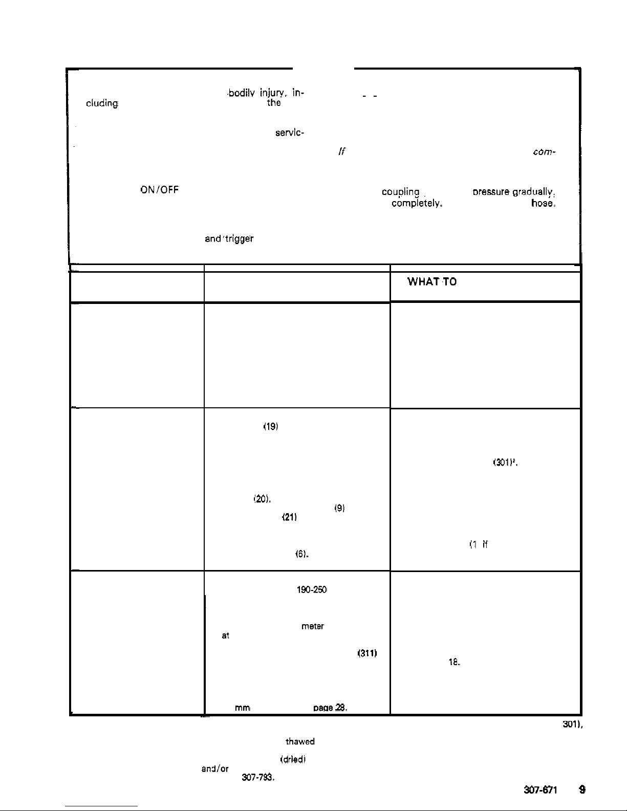
TROUBLESHOOTING GUIDE
WARNING
To reduce the risk of serious .bodilv
injury.
in-
Pressure
Relief
Procedure
6.
Engage the gun safety latch.
cluding fluid injection, splashing fluid in ihe eyes
7.
Ooen the drain valve. havina a container readv
~~
or on the skin, or injury from moving parts or elec
-
to
catch the drainage.
tric shock, always follow this procedure whenever
you shut
off
the sprayer, when checkingor servic-
8.
Leave the drain valve open until you are ready
ing
any part of the spray system, when Installing,
to spray again.
you stop spraying.
cleaning or changing spray tips, and whenever
pletely clogged, or thatpressure has not been fully
If
you suspect that the spray
tip
or hose
is
com-
1.
Engage the gun safety latch.
relieved after following the steps above, VERY
2.
Turn
the
ON/OFF switch to
OFF.
SLOWLY loosen the
tip
guard retaining nut or
hose end
couolina and relieve oressure araduallv.
I
3.
Unplug
the
power supply cord. then loosen comphely. Nowciearthe tip or hosb:
4.
Disengage the gun safety latch.
5.
Hold a metal part of the gun firmly to the side of
a grounded metal pail,
and3rigger the gun to
relieve pressure.
I~~~~
TYPE
OF
PROBLEM
MOTOR
WONT
OPERATE
Basic Fluid Pressure Problems
Basic Mechanical Problems
Basic Electrical Problems
WHAT TO CHECK
If
check is
OK,
go
to next check
1.
Check the pressure control knob sening.
The motor
will
not run if
it
is at the
minimum sening (fully
counterclockwise).
2.
Check for a clogged spray tip. Refer
to
your separate gun or tip instruction
manual.
-
-
-
-
i
1
it,
due
to
exposure
to low temperatures, by placing
it
in
a
'Thaw the sprayer if water or water-based paint has frozen in
warm area.
Do
not try to start the sprayer until
it
has thawed
completely. If the bourdon tube was not damaged by the
freezing, the pump should operate. If paint hardened (dried1 in
the sprayer. the pump packings and/or bare pressure control
mum be replaced.
See
page
23
or manual
307-793.
1.
Check for frozen or hardened paint
in
the pump (19) andlor pressure control
bourdon tube. Using a screwdriver,
carefully try to rotate fan
at
back of
motor.
See
page
15.
2.
Check displacement pump connecting
rod pin
(m).
It
must be completely
pushed into connecting rod
(91 and
spring retainer
(21)
should be firmly in
groove of connecting rod. See page
26.
3.
Check for motor damage. Remove drive
to
rotate fan bv hand.
housing assembly
(6).
See page
25.
Try
1.
Check electrical supply with volt meter.
Meter should read 190-250
Volts.
2.
Check extension cord for visible
damage. Use a volt meter or
test
lamp
m
extension cord outlet
to
check.
3. Check sprayer power supply cord
(311)
for visible damage such
as
broken in
-
sulation or wires.
4.
Check motor brush leads, terminals and
brush length. Brush length should be
14
mm minimum. See
DaQe
28.
WHAT.TO
DO
If
check is
NOT
OK
refer to this column
1. Slowly increase the pressure setting to
see
if
the motor starts.
2.
Relieve pressure, refer
to
your separate
gun or tip instruction manual for tip
cleaning.
1.
Thaw'.
Plug
in
sprayer
and
turn
on.
Slowly increase pressure setting
to
see
if
motor starts. If
it
doesn't, replace the
displacement pump packings
(see
manual
307-793)
andlor replace the bare
23.
pressure control box (3011'. See page
2.
Push pin into place and secure with the
spring retainer.
3.
Replace motor I1 1 if
fan won't turn.
1.
Reset building circuit breaker; replace
building fuse. Try another electrical
outlet.
2.
Replace extension cord.
3. Replace power supply cord.
See page 18.
4.
lighten terminal screws; replace
brushes. See page
27.
'When replacing the bare pressure control box (item
301).
trical hardware and reinstall these parts in the bare box.
remove the ONlOFF switch, bridge, circuit board and elec
-
Troubleshooting continued on next page.
307-671
9
Page 11
TYPE
OF
PROBLEM
MOTOR
WON7
OPERATE
Diagnosing circuit board
in
-
dicator lamps. The normal
condition is red lamp on,
clear lamp
on
when board
is
telling
pump
to
run.
cedure
Warning. Remove
Follow
Pressure Relief
Pro-
gun from hose. Remove
pressure control cover and
check for faulty condition of
circuit board lamps.
Condition A both lamps on;
pump won't operate and
motor is not running
Condition B
Both lamps
off
~~~~~~
WHAT TO CHECK
If
check
Is
OK,
go
to
next check
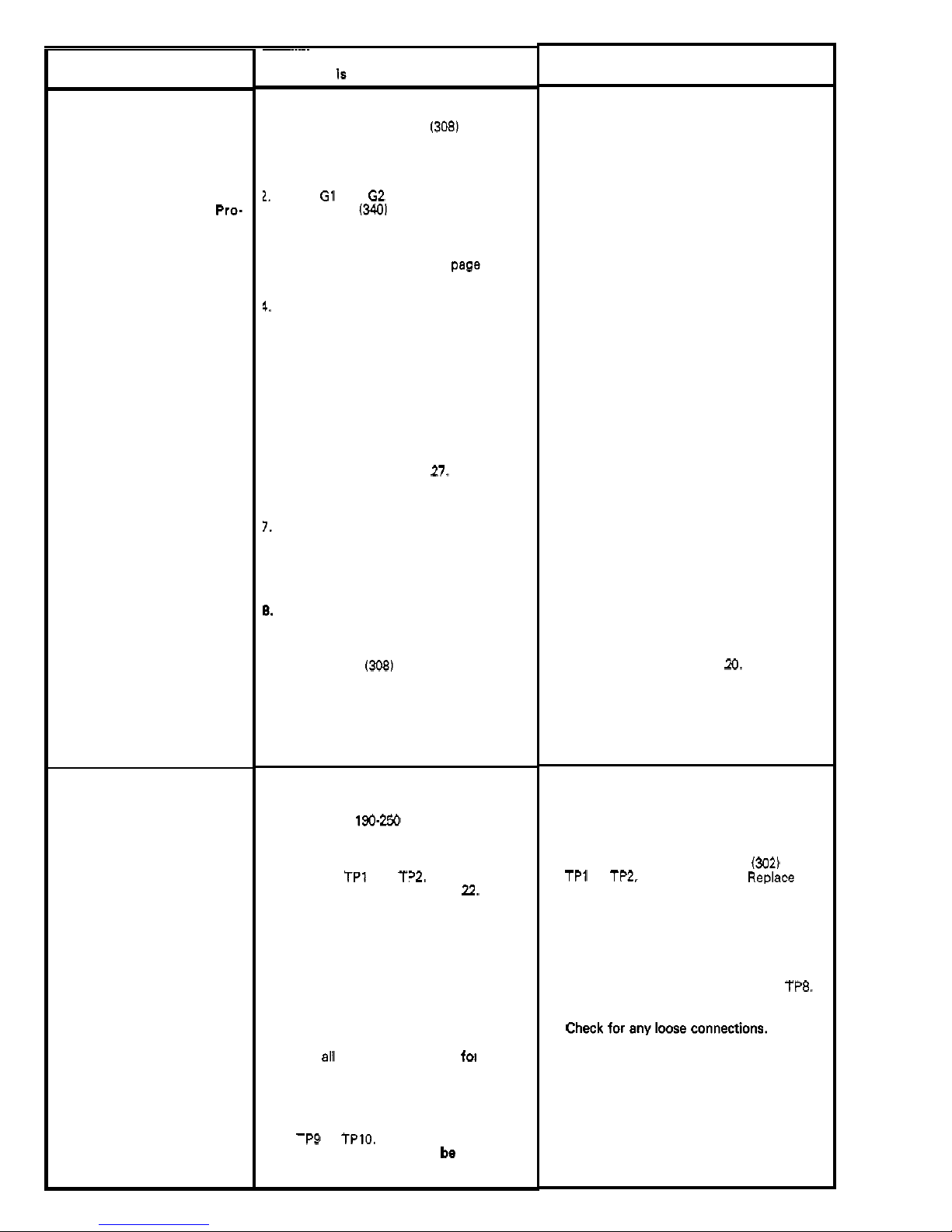
I.
Check leads from bridge 1308) to motor
to be sure they are securely fastened
and properly mated.
1.
Check G1 and G2 connections between
circuit board
(3401
and bridge
1308)
for
damage or loose terminals.
3.
Check for loose motor brush lead con
-
nections and terminals. See page 27.
4.
Check brush length which should be 14
mm minimum.
See
page 27.
at the same rate on both sides of the
NOTE also
that
the brushes do not wear
motor.
5.
Check for broken or misaligned motor
brush springs. Rolled portion of spring
must rest squarely on top of brush. See
page
27.
6.
Check motor brus'hes for binding
in
brush holders. See page
27.
7.
Check motor armature commutator for
burn spots, gouges and axtreme
rouohness. Remove motor cover and
brush inspection plates to check.
See
page
27.
6.
Check motor armature for shorts using
armature tester (growler) or perform spin
test.
See
page 15.
9.
Check bridge
1308)
by substituting with
a good bridge or performing bridge test.
See
page 16.
CAUTION: D
O
not perform this check
until
armature is determined to be good.
A bad armature will immediately burn
out
a
good bridge.
1. Check electrical supply. Connect
voltmeter to electrical outlet. Meter
should read
190.250 Volts.
2.
Check power supply to circuit board
with sprayer turned ON. Measure
voltage at
TPl and TP2. Meter should
read 190
-
250
Volts.
See page
7.2.
3.
Check a11 terminals and wires fog
damage or loose fit.
4.
Check motor thermal cutout switch.
Unplug sprayer. Allow motor to cool.
at
TP9 to TPlO. Use ohmmeter to check
Disconnect motor thermal switch leads
continuity. Switch should
be closed
when motor is cool.
WHAT TO DO
If
check is
NOT
OK
refer to this column
1.
Replace any loose terminals and crimp
to leads. Be sure male terminal blades
are straight and firmly connected to
mating part.
2.
Clean circuit board male terminals.
Replace loose or damaged terminals.
Securely reconnect leads.
3.
Tighten terminal screws. Replace
brushes if leads are damaged.
See page 27.
4.
Replace brushes. See page 27.
5. Replace spring
if
broken. Realign spring
with brush. See page
27.
6.
Clean brush holders. Remove carbon
with small cleaning brush. Align brush
free vertical brush movement.
lead with slot in brush holder to assure
7. Remove motor and have motor shop
resurface commutator if possible. See
page 27.
8.
Replace motor. See page
29.
9.
Replace bridge. See page
20.
1. Reset circuit breaker or replace outlet
fuse.
If
circuit breaker or fuse continues
to
open, see "Electrical Short", page 14.
2. Unplug sprayer. Check continuity of
TPl to TPZ, and TP2 to TP3.
Replace
both poles of ONlOFF switch
(302) from
switch
if
faulty.
Check continuity of
RFI
filter (3101 from
TP4 to TP6 and TP3 to TP5. Replace
filter if faulty.
tinuity
from TP5 to TP7 and TP6 to
TP8.
Check
power supply cord (3111 for
con
-
Replace cord if faulty.
3. Replace damaged terminals and recon
-
nect securely.
4.
Replace electric motor
if
switch does not
close when motor is cool. See page
29.
10
307-671
Page 12
YPE
OF
PROBLEM
Condition
B
(continued)
Condition
C
Red
lamp on, clear lamp
off
Unplug
sprayer1
WHAT TO CHECK
f
check is
OK,
go
to
next
check
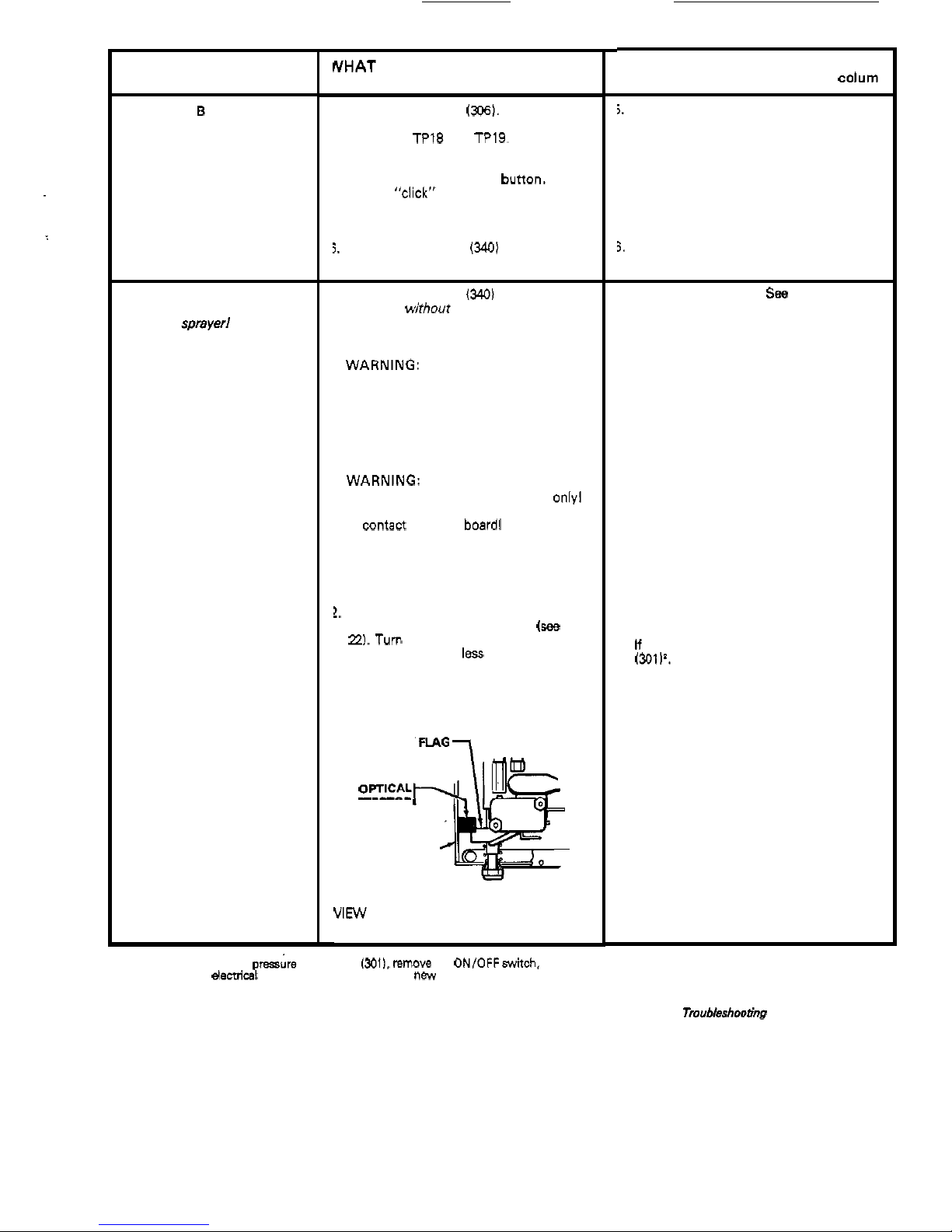
i.
Check microswitch
1306).
With no fluid
pressure in the pressure control discon
-
nect wires TP18 and TP19. Check con
tinuity across switch terminals with an
ohmmeter. Switch contact should be
closed. Depress actuator
bunon. An
audible
"click" indicates the contacts
have opened. Ohmmeter should read in
-
finity.
i.
Check circuit board
(3401
by substituting
with a good board. See page
22.
.
Check circuit board
(3401
by removing
from box
wirhout
disconnecting wires;
sea
page
22
for removal procedure.
WARNING:
Removing the circuit board
while still wired over
-
rides the optical
.
to over-pressurize, if the microswitch
detector which could cause the sprayer
does not function properly. Tum the
sprayer on
ONLY
long enough to check
lamp condition, then shut
off
immediate
-
ly.
WARNING:
To reduce the risk of elec
-
tric shock, handle board by edges only1
Do
not allow any metal objects to come
in
contacl with the boardl
should be
on
now - removing the circuit
Plug in and turn on sprayer. Clear lamp
board over
-
rides the optical detector.
Turn
off
and unplug sprayer.
!.
Check bourdon tube flag and detector
position. Reinstall circuit board
(see
page
22.
Turn pressure setting to maximum;
flag should extend
less
than half way into
optical detector slot from the bonom.
DETECTOR
C
I
R
C
U
I
T
-
BOARD
VIEW
OF
OPTICAL DETECTOR AND
FLAG
'When replacing
the
bare pressire control box 13011.
remow
the
ON/OFFswitch,
bridge,
circuit
board
and
elecbical
hardware and
reinstall
in
the
new bare box.
WHAT TO
DO
If
check
is
NOT
OK
refer
to
this colurn
5.
Replace microswitch. See page 19.
3,
Replace circuit board. See page
22.
I.
Replace circuit board.
Sea
page
22.
2.
Calibrate pressure control to
sea
if
that
corrects problem.
See
page
24.
If
not, replace bare pressure control box
13011'.
See
page
23.
Tmubleshooting continued on next
page.
307-671
11
Page 13
~~
TYPE
OF
PROBLEM
LOW OUTPUT
NO OUTPUT
Motor runs and pump stroke:
307-671
WHAT
TO
CHECK
If
check is
OK.
go to next check
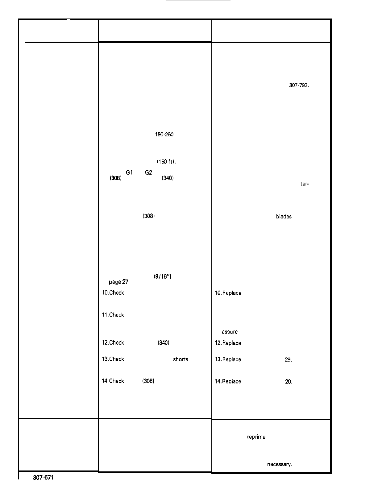
1. Check for worn spray tip.
2. Check
to
see
that
pump does not con
-
tinue
to
stroke when gun trigger is
released. Plug in and turn on sprayer.
Prime with paint. Trigger gun momen
tarily, then release and engage safety
latch. Relieve pressure, turn
off
and
unplug sprayer.
3. Check electrical supply with volt meter.
Meter should read
190-250
Volts.
4. Check extension cord size and length;
must be at least 12 gauge wire and no
longer than 15.2 m
(150
ft).
5.
Check G1 and G2 leads from bridge
or loose wires or connectors. Refer
to
WX)
to
circuit board
1340)
for damage
page
22.
6.
Check stall pressure. Refer
to
Calibration
Procedure on page 24.
7.
Check bridge
(308)
+
and - leads and
terminals
to
motor. Inspect
wiring
in
sulation and terminals for signs of
overheating. See page
20.
8.
Check for loose motor brush leads and
terminals. See page
27.
9.
Check for worn motor brushes which
should be 14 mm
(9/16) minimum. See
pBge
27.
10.Check for broken and misaligned motor
brush springs. Rolled portion of spring
must rest squarely on top of brush.
11.Check motor brushes for binding
in
brush holders. See page 27.
12.Check circuit board
1340)
by substituting
with a good circuit board. See page
22.
13.Check motor armature for shorn by us
-
ing an armature tester (growler) or per
-
form spin
test.
See
page 15.
14.Check bridge
(308)
by substituting with
a good bridge or by performing the
bridge test. See page 16 or
20.
CAUTION:
Do
not perform this check
A bad armature
will
immediately burn
until armature is determined
to
be good.
out
a
good bridge.
1.
Check paint supply.
2. Check for clogged intake strainer.
3. Check for loose suction tube or fittings.
WHAT
TO
DO
If
check
is
NOT
OK
refer to this column
1. Follow Pressure Relief Procedure
Warning then replace
tip.
See your
separate gun or tip manual.
2.
Service pump. See manual 307-793.
3. Reset building circuit breaker; replace
building fuse. Repair electrical outlet or
try
another outlet.
4. Replace with a correct, grounded exten
-
sion cord.
5.
Clean circuit board male terminals.
minals. Securely reconnect lead
ter-
Replace loose or defective lead ter
-
minals to board.
6.
Calibrate pressure control. See page 24.
7. Be sure male terminal
blades are
centered and firmly connected to female
terminals. Replace any loose terminal or
damaged wiring. Securely reconnect
wires to bridge.
8.
Tighten terminal screws. Replace
brushes if leads are damaged. See page
27.
9.
Replace brushes. See page
27.
10.Replace spring if broken. Realign spring
with brush. See page
27.
11 .Clean brush holders, remove carbon
dust with small cleaning brush. Align
brush lead with
slot
in brush holder
to
assure free vertical brush movement.
12.Replace circuit board. See page
22.
13.Replace motor.
See
page
29.
14.Repiace bridge. See page
20.
1. Refill and reprime pump.
2.
Remove and clean, then reinstall.
3. Tighten; use thread sealant or sealing
tape on threads if
necessary.
Page 14
TYPE OF PROBLEM
NO OUTPUT
(Continued)
Motor runs but pump does
not stroke
EXCESSIVE PRESSURE
FLUCTUATIONS
Spray panern variations.
MOTOR IS HOT
e
RUNS INTERMllTENTLY
WHAT TO CHECK
If
check is
OK,
go
to next check
,
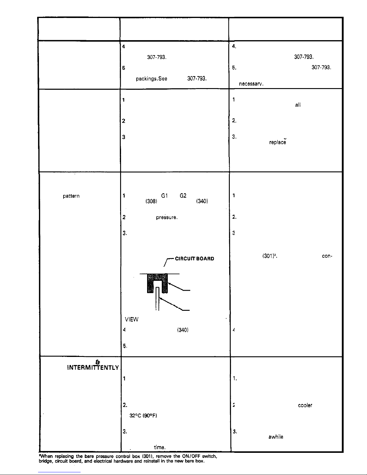
Check to see
if
intake valve ball and
piston ball are seating properly.
See
manual 307-793.
.
Check for leaking around throat packing
nut which may indicate worn or damag
-
ed packings.See manual 307-793.
.
Check displacement pump connecting
rod
pin.
See
page 26.
,
Check connecting rod assembly for
damage. See page 25.
.
Be sure crank
in
drive housing rotates;
plug
in
sprayer and turn on momentarily
to check. Turn
off
and unplug sprayer.
See
page 25.
.
Be sure both G1 and G2 leads from
firmly
connected. See
page
22.
bridge
1308)
to circuit
board
13401
are
'.
Check stall pressure. Refer to Calibration
procedure on page 24.
i.
Check bourdon tube flag and detector
position. Turn pressure sening to max
-
imum; flag should not drag or bind
in
optical detector slot of circuit board.
r
CIRCU'TBoARD
OPTICAL
DETECTOR
"
OPTICAL
DETECTOR
FLAG
VIEW
OF OPTICAL DETECTOR AND FLAG
I.
Check circuit board
(3401
by substituting
with a good board. See page
22.
i.
Check
LOW
OUTPUT section on page
12.
.
Check to
see
if
sprayer has been
operating at high pressure with small
tips, which causes low motor RPM and
results
in
excessive heat build up.
I.
Check to
see
if ambient temperature
where sprayer is located is more than
32%
(90°F)
or
if
sprayer
is
located
in
direct sun.
!.
Check to
see
if
sprayer has been left in a
stalled condition [sprayer turned on,
pressurized, but not operating) for long
periods of
time.
WHAT TO
DO
If
check
is
NOT
OK
refer to this column
,.
Remove intake valve and clean. Check
balls and seats for nicks; replace if
necessary. See manual
307-793.
#.
Replace packings. See manual 307-793.
Also check piston valve seat for harden
-
ed
paint or nicks and replace
if
necessarv.
.
Replace pin if missing. Be sure retainer
spring is fully in groove
a11 around
connecting rod. See page 26.
!.
Replace connecting rod assembly. See
page 25.
i.
Check drive housino assemblv for
damage and
replac; if necessary.
See
page
25.
.
Reconnect securely. See page
22.
I.
Calibrate pressure control. See page 24.
I.
Carefully bend flag into alignment with
detector slot to see if that corrects pro
-
blem.
assembly
(3011'. Calibrate pressure con-
If not, replace bare pressure control
trol after reassembly.
I.
Replace circuit board. See page
22.
I.
Decrease pressure sening or increase
tip
size.
!.
Move sprayer
possible.
to shaded, coolel ' area if
1.
Turn
off
sprayer whenever you stop
spraying for
awhile and relieve fluid
pressure.
307-671
13
Page 15

TYPE
OF
PROBLEM
ELECTRICAL SHORT
Buildino circuit breaker ooens
as
sooi
as sprayer switch
is
turned on.
CAUTION
Any short in any part of
thf
motor power circuit, which
i$
connected to the output sidc
of the bridge, will cause
thf
bridge to burn out immediate
ly. Correctly diagnose anc
ing and
replacing
bridge
repair all shorts before
check,
as soon as sprayer is plugged
Building circuit breaker opens
turned on.
into outlet and sprayer is
NO1
WHAT TO CHECK
If
check
Is
NOT
OK
refer to this
col
-
If
check
is
OK,
go
to
next check
WHAT TO DO
umn
Check all electrical wiring for damaged
or damage. Be sure to check wires
bet-
insulation, and all terminals for loose
fit
ween pressure control and motor which
are encased in conduit
141
I.
See page
29.
1.
Repair or replace any damaged wiring or
terminals. Securelv reconnect all wires.
,
Check for missing inspection plate
2.
Correct faulty conditions.
gasket
(see page
27).
bent terminal forks
which could cause a short.
or other metal to metal contact points
Check motor armature for shorts by us
-
3.
Replace motor. See page
29.
ing an armature tester (growler) or per
-
form spin test. See page
15.
Inspect
windings for bums.
,
Check bridge
(3081
by substituting with
4.
Replace bridge. See page
20.
a good bridge
or
by performing bridge
test.
See page
16.
CAUTION:
Do
not perform this check
until armature is determined to be
good.
A bad armature will immediately burn
out a good bridge.
Check 'Basic Electrical Problems' on
page
9.
Check ON/OFF switch
1302)
See page
19.
Be
sure
the
sprayer
is
unplugged!
switch with ohm meter. The ohm meter
Disconnect wires from switch and check
should read
infinity
with the ONlOFF
switch OFF, and zero with the switch
ON.
CAUTION:
A short
in
the motor circuit
will burn the bridge out immediately,
which in turn usually causes the ONlOFF
switch
to
fail in the closed mode.
2.
Replace ON/OFF switch. See page
19.
14
307-671
Page 16
~
~_____~
SPIN
TEST
WARNING
Before doing this procedure, follow the Pressure
the risk of
a
fluid injection injury, splashing fluids
Relief
Procedure Warning on page
17
to reduce
in the eyes or on the skin, injury from moving
Darts. or electric shock.
1
~~~ ~~
For checking armature, motor winding and brush elec
-
trical continuity.
Setup
Remove the drive housing from the sprayer as des
-
cribed in Steps
1-9,
page
25.
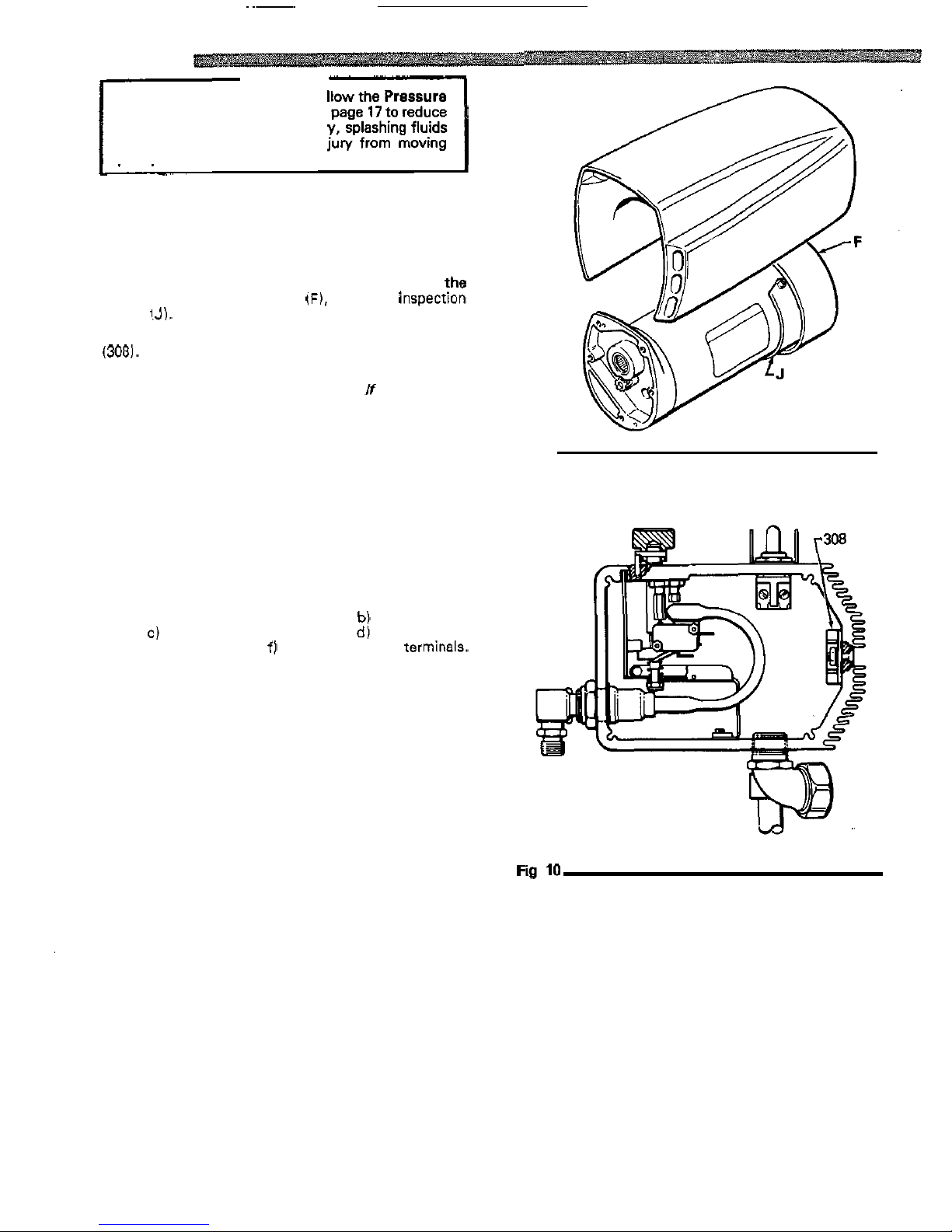
Remove the pressure control cover and screws, !he
motor cover, the fan cover (F), and the inspectton
covers
IJ).
See Fig
9.
Disconnect the
two
leads from the motor to the bridge
(308).
See
Fig
10.
Armature
Short
Circuit Test
shorts,
the motor will coast
two
or three revolutions
Quickly turn the motor fan by hand.
If
there are
no
before coming to a complete stop.
If the motor does not spin freely and resists rotation, the
armature
is
shorted and the motor must be replaced.
See page
29.
Armature, Brushes, and Motor Wiring Open
Circuit Test (Continuity)
Connect the
two
black motor leads together with a test
lead.
Turn the motor fan by hand
at
about
two
revolutions
per second.
following:
a)
broken brush springs;
b)
broken brush
If there
is
uneven or no turning resistance, check the
leads;
c) loose brush terminal screws; d) worn brushes;
e)
broken motor leads;
f)
loose
motor lead termlnals.
Repair parts as needed. See page
27.
If there
is
still uneven or no turning resistance, replace
the motor. See page
29.
Fig
9
307-671
15
Page 17
BRIDGE
TEST
Remove the bridge from the pressure control box and
perform this test to determine if the bridge is functional.
continuity tester, such
as
multi-meter set on the X1
See Bridge Rectifier Replacement, page
20.
Use
a
ohms scale
(
n
).
the bridge fails even one test,
it
must be replaced.
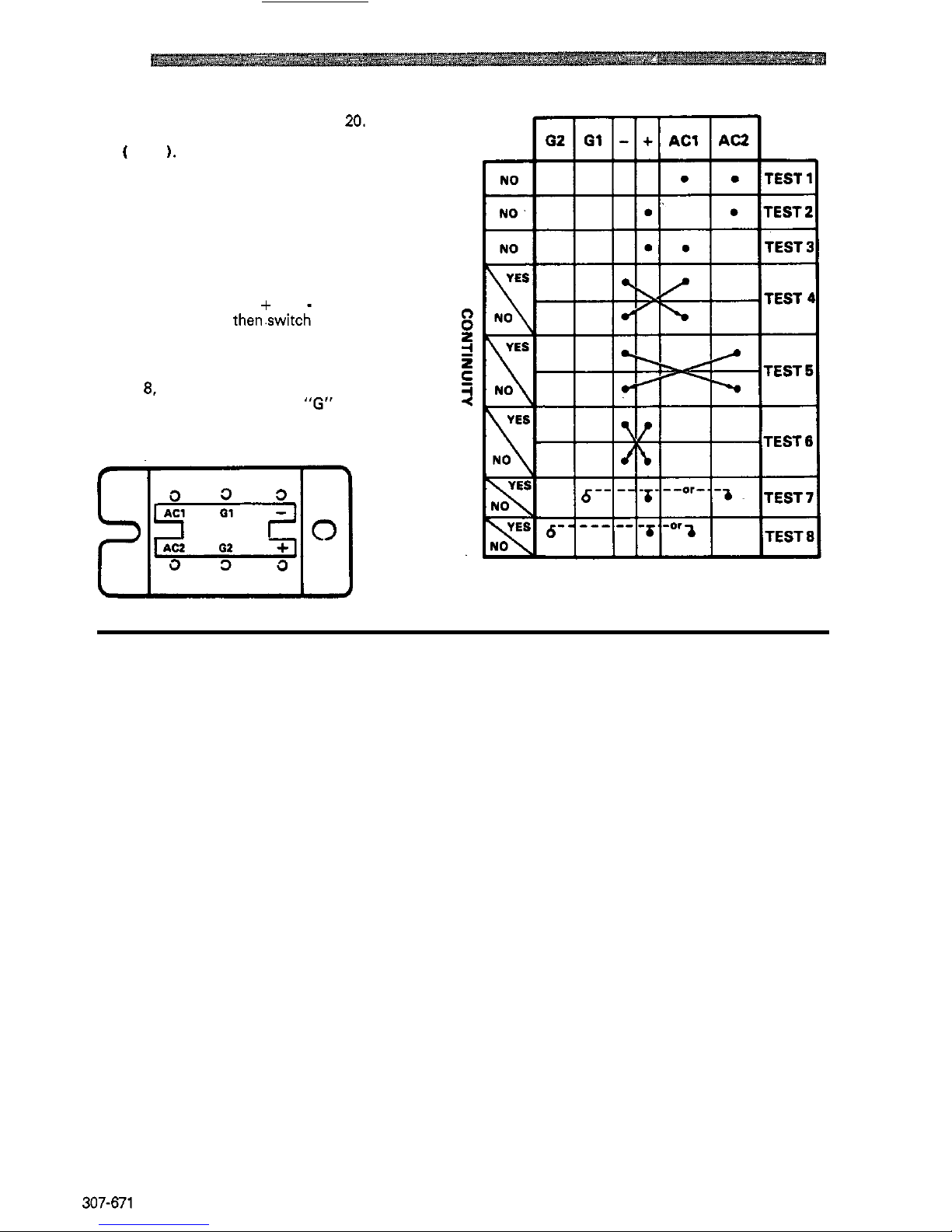
Eight individual checks, or tests, must be performed.
If
Fig
11
shows the position of the wires on the bridge.
Us
-
ing the chart
at
the right, connect the meter wires
as indicated by the black dots for each test, then check the
continuity.
In Tests 1,
2
and
3,
there should be
NO
continuity.
indicated, check continuity,
then.switch the meter wire
In Tests
4, 5 and
6,
connect the + and - meter wires
as
get
NO
continuity one way, and
YES
continuity the
connections and check continuity again.
You
should
other way.
In Tests 7 and
8.
connect the meter wires
as
indicated
by
the black dots. Touch the indicated
"G"
wire to one
meter wire, and then the other.
You
should get
NO
con
-
tinuity one way, and
YES
continuity the other way.
BRIDGE
WIRES
Fig
11
16
307-671
Page 18
GENERAL
REPAIR
NOTES
WARNING
Pressure Relief Procedure
To'reduce the risk of serious bodily injury,
in
-
cluding fluid injection, splashing fluid in the eyes
or on the skin, or injury from moving parts or elec
tric shock, always follow this procedure whenever
you shut
off
the sprayer, when checking or servic:
ing any part of the spray system, when installing,
cleaning or changing spray tips, and whenever
you stop spraying.
1 .Engage the gun safety latch.
2 .Turn the
ONIOFF switch to OFF.
3
.Unplug the power supply cord.
4 .Disengage the gun safety latch.
5
.Hold a metal part of the gun firmly to the side of
a grounded metal pail, and trigger the
gun
to
relieve pressure.
6
.Engage the gun safe& latch.
7 .Open the drain valve, having a container ready
8
.Leave the drain valve open until you are ready
If
you suspect that the spray
tip
or hose
is
com
-
pletely clogged, or that pressure has not been fully
relieved after following the steps above, VERY
SLOWLY loosen the tip guard retaining nut or
hose end coupling and relieve pressure gradually,
then loosen completely. Now clear the
tip
or hose.
to catch the drainage.
to spray again.
Tool
List
The following tools are needed when repairing this
sprayer.
Phillips screwdriver
Small flatblade screwdriver
Needle nose pliers
Plastic mallet
Adjustable wrench
2
"
adjustable, open-end wrench
Torque wrench
114"
hex key wrench
3/16
"
hex key wrench
518"
socket wrench
318"
open end wrench
314"
open
end wrench
112''
open
end wrench
718"
open end wrench
High quality motor oil
Bearing grease
318
ignition wrench
For calibration procedure only:
0.015'
spray tip
High pressure, oil
-
filled test gauge, Part No. 102-814
5
gallon pail
Clean water
Mineral spirits
NEW
207
bar
(3oM)
psi) high pressure spray hose,
Part
No.
214-915.
ing
general repair notes and the repair procedure. Be
Before repairing any part of the sprayer, read the
follow-
sure you have the necessary tools and parts available.
1.
When disconnecting wires
in
the pressure control
assembly, use needle nose pliers to separate mating
connectors.
When reconnecting the wires, be sure the flat blade
wrap
-
around blade of the female connector when
of the insulated male connector is centered
in
the
the connection is made.
CAUTION
tion, be sure to properly mate connectors, and
never pull on a wire to disconnect
it.
Pulling on a
wire could loosen the connector from the wire.
2.
Route wires in the pressure control assembly
carefully through the legs of the U
-
shaped bourdon
tube, where appropriate, to avoid interfering with
the bourdon tube which moves as the pressure set
-
ting changes and to avoid pinching the wires be
-
tween the pressure control box and cover.
CAUTION
Improper wire routing can result
in
poor sprayer
performance or damage to the pressure control.
3.
Keep
all
screws, nuts, washers, gaskets, and elec
trical fittings removed during repair procedures.
These parts are not normally provided with replace
-
ment assemblies.
4.
Test your repair before regular operation of the
sprayer to be sure the problem is corrected.
If the sprayer does not operate properly, review the
repair procedure again to verify that everything was
done correctly. If necessary, refer to the
Troubleshooting Guide, pages
9-16,
to help identify
other possible problems and solutions.
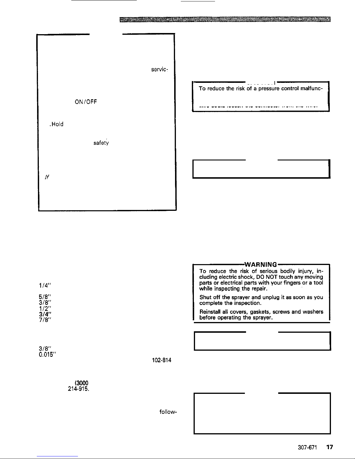
FWARNlNGl
To reduce the risk of serious bodily injury, in
-
cluding electric shock, DO NOT touch any moving
while
inspecting.the repair.
parts or electrical parts with your fingers or a tool
complete the inspection.
Shut
off
the sprayer and unplug
it
as soon as you
before operating the sprayer.
Reinstall all covers, gaskets, screws and washers
CAUTION
seconds to avoid damaging the pump packings.
Do not run the sprayer dry for more than
30
5.
Reinstall the motor cover before regular operation
of the sprayer and replace
it
if
it
is damaged. The
cover directs cooling air around the motor to help
prevent overheating.
It
can also help prevent burns,
fire or explosion; see the WARNING, below.
WARNING
and could burn your skin if touched. Flammable
During operation, the motor becomes very hot
materials spilled on the hot, bare motor could
cause a fire or explosion. Always have the motor
cover in place during regular operation to reduce
the risk of burns, fire or explosion.
307-671
17
Page 19
POWER SUPPLY CORD REPLACEMENT
(See
Fig 12
Et
131
WARNING
follow the Pressure
Relief Procedure Warning on page 17 to reduce
the risk of
a
fluid injection injury, splashing in the
eyes or on the skin, injury from moving parts, or
electric shock.
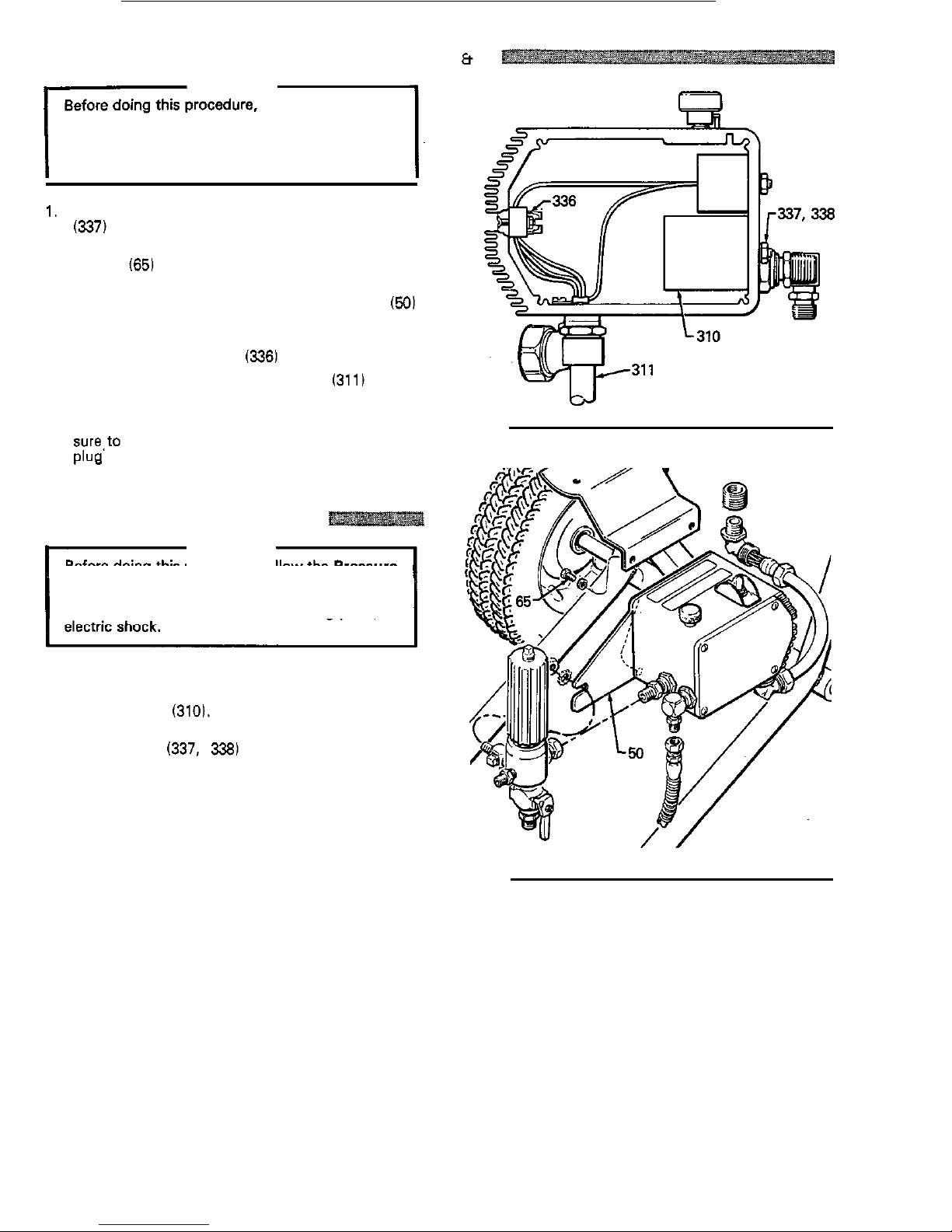
1. Use the
19
mm open end wrench to remove the nut
(337)
from the filter stud (310).
2.
Use
the
13 mm socket wrench to remove the
two
screws (651 holding the pressure control to the
frame.
3. Remove the pressure control mounting bracket
(50)
using a Phillips screwdriver.
4.
Disconnect the power supply cord wires from the
control box terminal strip
(336) using a screwdriver.
5. Install the new power supply cord
(3111 in the
reverse order of disassembly.
Install
a
new plug on the other end
of
the cord. Be Fig
12
sure,to follow
all
local codes regarding the type of
olua to use.
.I
FILTER REPLACEMENT
(See Fig 12)
WARNING
Before doing this procedure, follow the Pressure
the risk of
a
fluid injection injury, splashing in the
Relief
Procedure Warning on page 17 to reduce
eyes or on the skin, injury from moving parts, or
1. Remove the pressure control cover and screws.
2.
Use
a
needle nose pliers to remove the four wires
from the filter (3101.
3.
Use the
M8
wrench to remove the lower nut and
lockwashers
(337,
338)
on the outside of the
pressure control box.
4.
Remove the old filter and install a new one in the
reverse order of disassembly.
Fig
13
18
307-671
Page 20
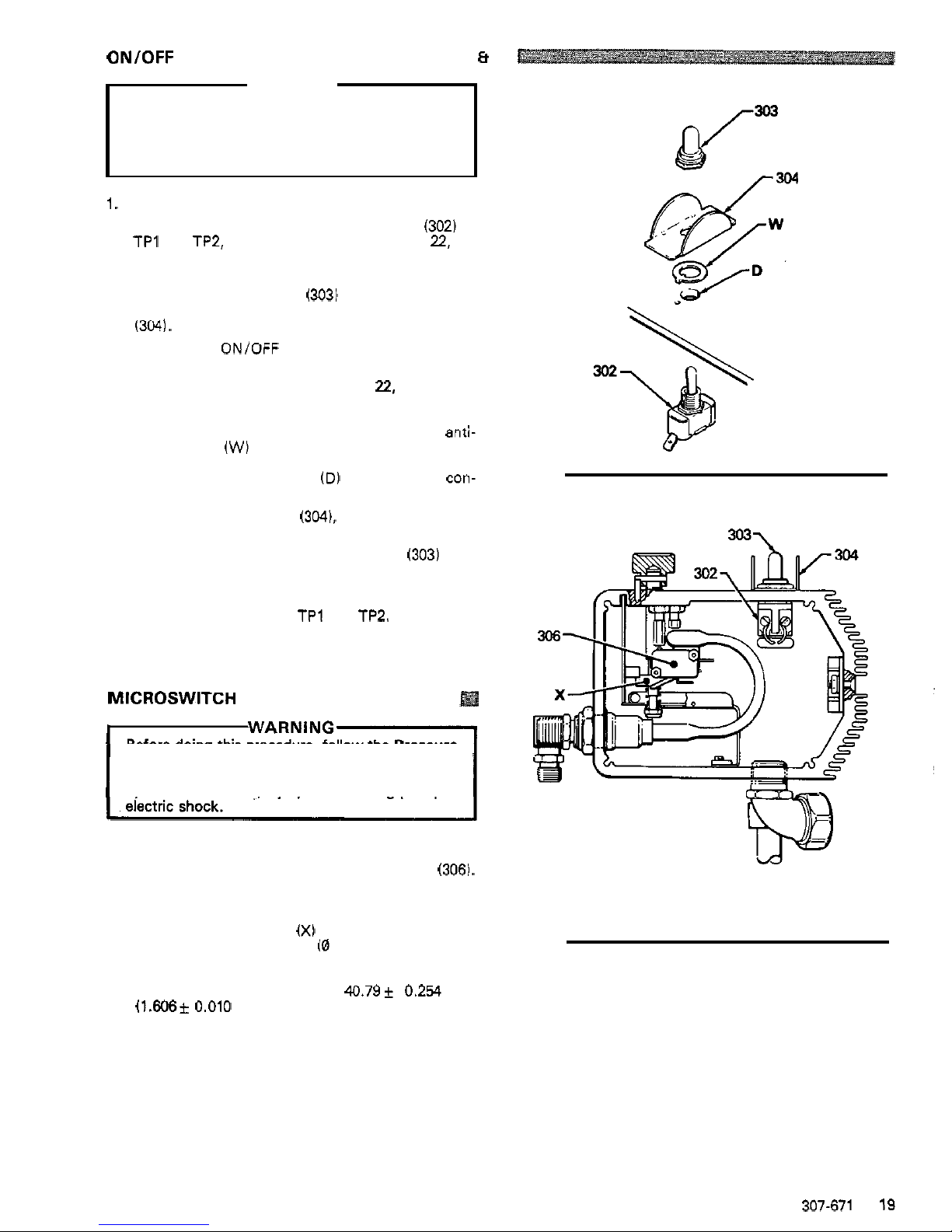
ON/OFF SWITCH REPLACEMENT
(See Figs 14
Et
WARNING
Before doing this procedure, follow the Pressure
Relief Procedure Warning on page 17 to reduce
the risk of
a
fluid injection injury, splashing
in
the
eyes or on the skin, injury from moving parts, or
electric
shock.
1. Remove the pressure control cover and screws.
2. Remove the wires attached to the switch
(302) at
TPl and TP2, using a screwdriver. See page
22,
Fig
21.
3.
Use a 16 mm socket wrench to loosen and remove
the nut and rubber boot
(303)
from the top of the
pressure control box. Remove the switch guard
(304).
4. Remove the ONIOFF switch.
5. Remove the wires attached to the switch TP4 and
TP3 using a screwdriver. See page
22,
Fig 21.
6. Attach the wires to TP4 and TP3 of the new switch.
7. Install the new switch
so
the internal tab of the anti-
rotation ring
(W)
engages with the vertical groove
engages
with
the blind hole
(D)
of the pressure con-
in
the threads of the switch, and the external tab
trol box.
8.
Install the switch guard (304). aligning the internal
tab with the groove
in
the threads.
9. Powder the inside of the rubber boot
(303)
with
talcum, then shake excess out of boot.
10. Install the nut and rubber boot and tighten.
11. Reconnect the wires to
TP1 and TP2.
12. Reinstall the pressure control cover and screws.
MICROSWITCH REPLACEMENT
(See Fig 15)
Before doing this procedure, follow the Pressure
the risk of a fluid injection injury, splashing
in
the
Relief Procedure Warning on page 17 to reduce
eyes or on the skin, injury from moving parts, or
1. Remove the pressure control cover and screws.
2. Disconnect both wires from the microswitch
(3061.
3. Use the socket wrench to remove the nuts from the
microswitch.
4. Check to see if the flag
(X)
is loose. If
it
is, be sure
the
fluid
pressure is 0 bar
(0
psi), then loosen the
two 6 mm hex nuts behind the microswitch. Adjust
the distance from the top of the flat to top inside
of
the pressure control box to 40.79k 0.254 mm
(1.606*
0.010
in.).
Tighten the screwsand recheck
the dimension. Refer to Fig 1.
5. Perform the
STALL
PRESSURE
CALIBRATION
on page 24 before regular operation of the sprayer.
6. Reinstall the cover
and
screws.
15)
Fig
14
Fig
15
307-671
19
Page 21
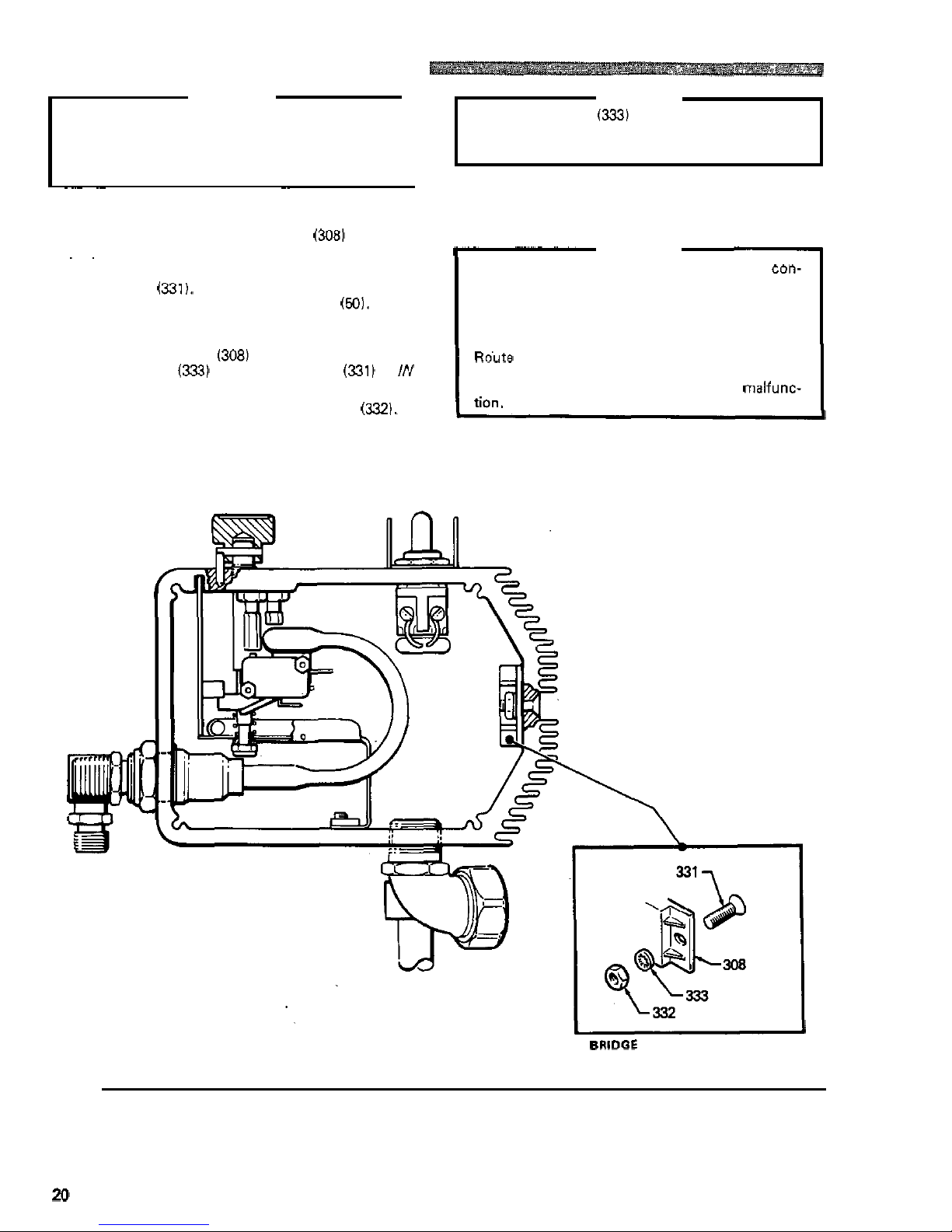
BRIDGE RECTIFIER REPLACEMENT
(See
Fig 161
WARNING
Before doing this procedure, follow the Pressure
the risk of a fluid injection injury, splashing
in
the
Relief Procedure Warning on page 17 to reduce
eyes or on the skin, injury from moving parts or
electric shock.
1
~ ~~~ ~~ ~~
1.
Remove the pressure control cover and screws.
2.
Disconnect all wires from the bridge
(3081
at the ap
-
propriate terminals.
.
CAUTION
The lockwashers
(333)
must be in front
of
the
bridge to avoid overheating which
will
result
in
bridge failure. Refer to the Detail
in
Fig 16.
6. Make sure the bridge is flush with the side of the box
7. Connect all wires. Carefully route the wires.
I-
CAUTION
and tighten the screws securely.
3. Outside the pressure control box on the right side are
Be sure the flat blade of the insulated male
con-
two
screws
(331).
Loosen,
but don't remove the
nector is centered in the wrap
-
around blade of the
screw near the back mounting plate
(50).
Then
female connector when the connections are
loosen and remove the front screw. Slide the bridge
made. Improper connections may cause the
out.
~~
sprayer to malfunction.
4.
Slide the new bridge
(308)
into the box being sure
the lockwasher
(333)
on the rear screw (331) is
/N
Ro'ute all wires carefully to avoid interference with
FRONT
of the bridge. Refer to the Detail in Fig 16.
the movement of the bourdon tube, circuit board,
or control box cover which could cause a
malfunc-
5.
Install the front screw, lockwasher and
nut
(332).
8.
Reinstall the pressure control cover and screws.
BRIDCE
INSTALLATION
DETAIL
Fig
16
20
307-671
Page 22
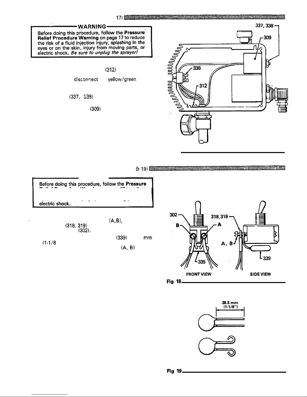
CHOKE REPLACEMENT
(See
Fig 17)
1. Remove the pressure control cover and screws.
2. Remove the grounding screw
(312) and remove the
lead. Loosen the appropriate screw on the terminal
lead.
strip (336) and
discornect the yellow/green choke
3.
Use
the M8 wrench
to
remove the upper nut and
lockwasher
(337,
US)
on the outside of the
pressure control box.
4.
Remove the old choke (309) and install a new one in
the reverse order of disassembly.
Fig
17
VARISTOR
REPLACEMENT
(See
Figs 18 8 19)
WARNING
Relief Procedure
Warning on page 17 to reduce
the risk of a fluid injection injury, splashing in the
eyes
or on the skin, injury from moving parts, or
n
1.
'
2.
3.
4.
5.
Remove the control box screws and cover.
Remove the
two
screws
(A$).
the wiring
harnesses
(318, 319) and the old varistor from the
ONlOFF switch
(302).
Trim the leads on the new varistor
(339)
to 28.5 mm
(1-118 in.). Turn each lead outward to form a loop
that
is
large enough for the screws
(A,
8) to pass
through.
loop
of
the varistor leads on each screw and thread
Place
a
wiring harness on each screw, then place
a
the screws into the switch.
Wrap the varistor under the switch.
n
FRONTVIEW
SIDEVIEW
307-671
21
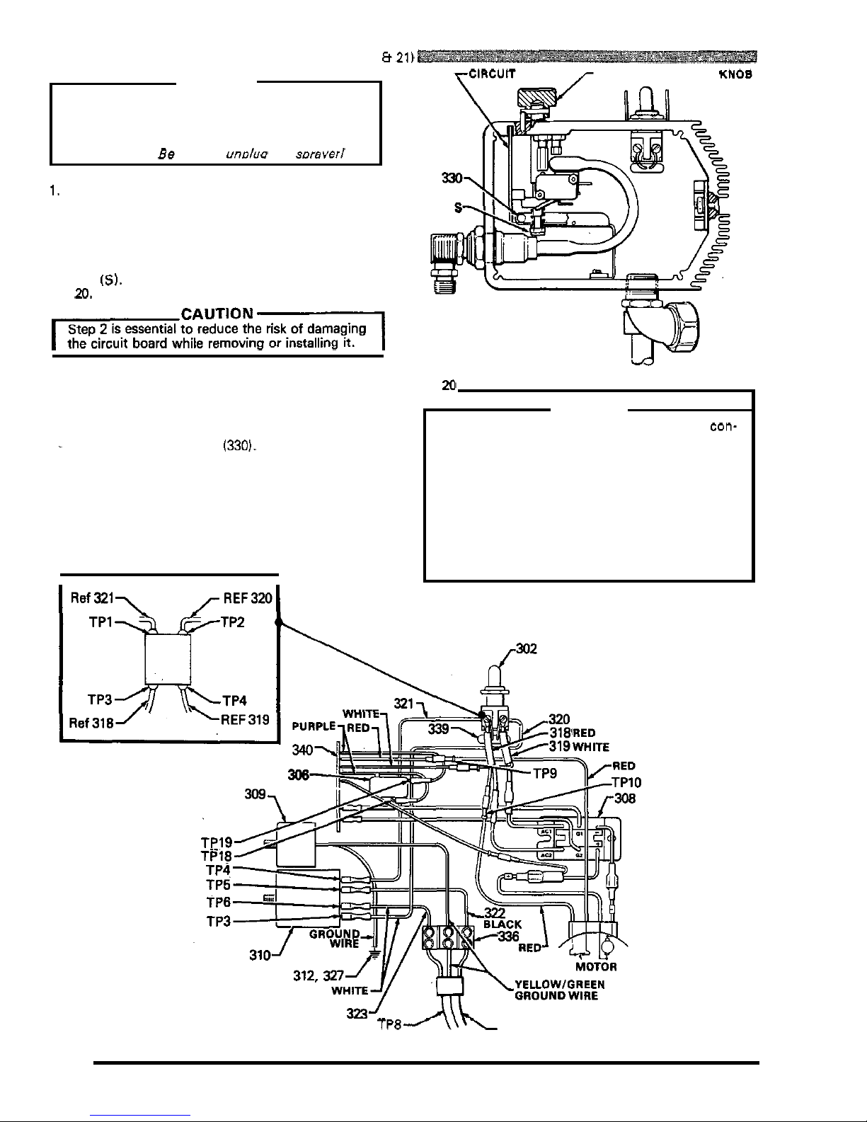
Page 23
CIRCUIT BOARD REPLACEMENT
(See
Figs
20
8
21)
WARNING
Before doing this procedure, follow the Pressure
the risk of a fluid injection injury, splashing
in
the
Relief Procedure Warning on page
17
to reduce
eyes or on the skin, injury from moving parts, or
electric shock.
Be sure
to
unolua
rhe soraverl
rClRCUlT
BOARD
r
PRESSURE CONTROL
KNOB
1.
Remove the pressure control cover and screws.
2.
Turn the pressure control knob all the way counter
clockwise to the minimum setting to release spring
tension on the board.
Also
check to be sure only
three or four threads
of
the pressure control knob
shaft are exposed below the pressure adjustment
nut
(SI.
Back down the nut, if necessary.
See
Fig
20.
IcAuTloNl
Step 2 is essential to reduce the risk of damaging
the circuit board while removing
or
installing
it.
3.
Disconnect
ALL
wires from the board, including the
two
heavy black wires. Pay close attention
to
where
connections are made.
See
Fig
21.
.
4. To
remove the board from the box, pull out the
-
black plastic-tipped pin
(330).
Push the
bottom
of
the circuit board toward the wall of the box and
carefully slide the board out.
5.
Install the board
in
the box at the Same angle as
it
was removed.
6.
Reconnect all wires. Refer to the wiring diagram
in
Fig
21.
Fig
P
CAUTION
nector is centered exactly
in
the wrap-around
Be sure the flat blade of the insulated male con-
blade of the female connector when connections
are made.
Route all wires carefully to avoid interference
with
the circuit board, bourdon tube and pressure con
-
trol cover.
These precautions are essential to reduce the risk
of malfunction.
7.
Perform the
STALL
PRESSURE
CALIBRATION
on page
24
if you installed a new board.
TP8
TP7
Fig
21
PLUQ
22
307-671
Page 24
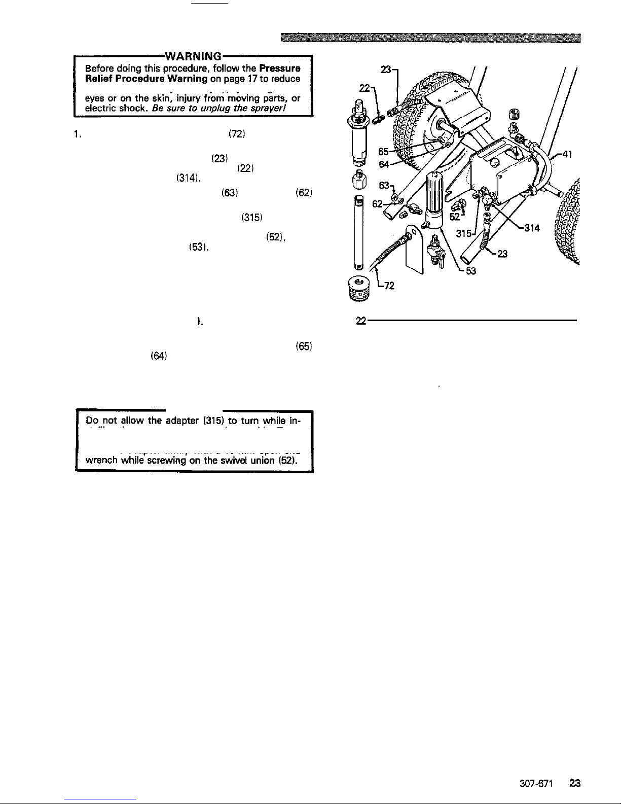
PRESSURE CONTROL REPLACEMENT
the risk of a fluid injection injury, splashing in the
1. Disconnect the main fluid hose (72) and the secon
-
dary fluid hose, if used, from the sprayer.
2. Disconnect the fluid hose
(23)
from between the
displacement pump outlet nipple
(22)
and pressure
control inlet elbow
(314).
3.
Loosen the filter bracket nut
(63)
and washer
(62)
using a 19
mm
open end wrench.
4.
Hold the pressure control adapter (315) firmly with
wrench to loosen the swivel union
(52).
then
a
19
mm
open end wrench.
Use
an adjustable
remove the fluid filter
(53).
5. Remove the pressure control cover and screws, and
terminals.
disconnect the four motor leads at the appropriate
6. Refer
to
CIRCUIT BOARD REPLACEMENT
on
page
22,
remove the circuit board and retain.
7.
Remove the conduit (41
1.
Fig
22
8.
Use
a
13 mm open end wrench to loosen and
remove the pressure control mounting screws 165)
and washers
(64)
located below the pressure con
-
trol box. Remove the box.
9. Install the new pressure control assembly
in
the
reverse order of disassembly.
CAUTION
stalling the new pressure control assembly. Turn
-
ing
it
can damage the sensitive bourdon tube.
Hold the adapter firmly
with
a 19 mm open end
10.
Perform the
STALL PRESSURE CALIBRATION
starting on page 24, before regular operation of the
sprayer.
307-671
23
Page 25
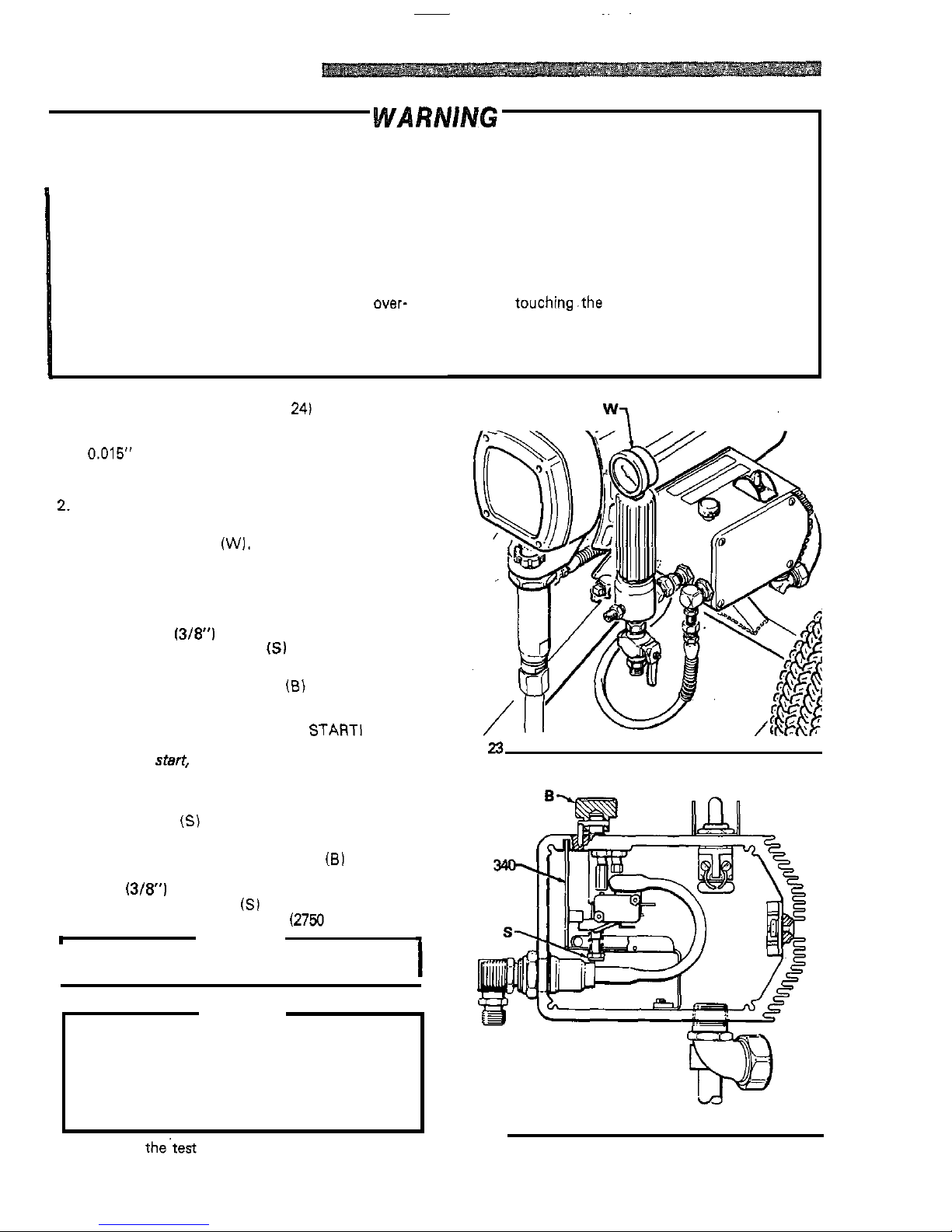
~ ~~
STALL
PRESSURE
CALIBRATION
I
WA
RNlNG
I
USE EXTREME CAUTION
WHEN PERFORMING
THIS CALIBRATION PROCEDURE
to
reduce the risk of a
fluid injection injury or other serious bodily injury which can result from splashing, component rupture, electric
shock, fire, explosion, or moving parts.
This procedure sets the sprayer to 192 bar (2750 psi)
MAXIMUM WORKING PRESSURE. This procedure
must be performed whenever a
new
or
used circuit
board, or pressure control assembly is removed and
reinstalled or replaced, to be sure the sprayer is pro
-
perly calibrated.
pressurize
and result
in
component
rupture, fire or
Improper
calibration can
cause the sprayer to
over-
explosion.
It
may also prevent the sprayer from ob
-
taining the maximum working pressure which would
result in poor sprayer performance.
Calibration Setup
(See
Fig
23
and 24)
1. Follow the Pressure Relief Procedure Warning
a
0.015' spray tip in the gun. Connect the gun
to
a
on page 17. Remove the spray hose and gun. Install
outlet.
new
test hose and connect the hose to the sprayer
2. Remove the pressure control screws and cover.
3. Remove the plug from the top of the
fluid
filter, and
4. Place the pump suction tube
in
a 5 gallon pail of
install the test gauge
(W).
clean water.
5.
Be sure the gun safety latch is engaged.
6. Use a 9 mm
(3/8') ignition wrench to turn the
pressure adjustment nut
(SI
counterclockwise
about
two
full turns. See Fig 24.
7. With the pressure control knob
(B) at
the
minimum
setting, turn the sprayer switch ON.
THE SPRAYER SHOULD NOT
STARTI
If
it
does start,
shut the. sprayer switch OFF,
disengage the
gun
safety latch, trigger
the
gun
into
a grounded waste container until pressure is reliev
-
ed. Engage the gun safety latch. Turn the pressure
adjustment
nut
(S)
a
little further counterclockwise.
Turn the sprayer on to be sure
it
does nor
start.
8.
Slowly
turn the pressure control knob
(81
clockwise
to the maximum setting and hold
it
there. Use a
9
mm
(3/8') ignition wrench to slowly turn the
pressure adjustment
nut
(S)
clockwise
until
the
test
gauge reads EXACTLY 192 bar
(2750
psi).
h
WARNING
1
I
Follow the Pressure Relief Procedure Warning
on page
17.
1
CAUTION
To
prevent pump corrosion,
flush the water out of
the pump, hose and
gun
with mineral spirits. Be
sure to close the drain valve, first.
Use
the lowest
pressure necessary to flush. Follow the Pressure
the mineral spirits
in
the pump to protect
it
until
Relief Procedure Warning
on
page
17.
Leave
you are ready to spray again.
9.
Remove the'test gauge assembly and reinstall the
plug. Flush out water
with
mineral spirits.
24
307-671
NEVER attempt to increase the fluid outlet pressure
by performing this calibration in any other way.
NEVER EXCEED 192 bar (2750 psi) MAXIMUM
WORKING PRESSURE. Normal operation
of
the
sprayer at higher pressures could result in compo
-
nent rupture, fire or explosion.
AVOID
touching.the wires
in
the pressure control
assembly with your fingers or
tools
when the control
box cover is removed to reduce the risk of electric
shock.
Fig
23
Fig
24
Page 26
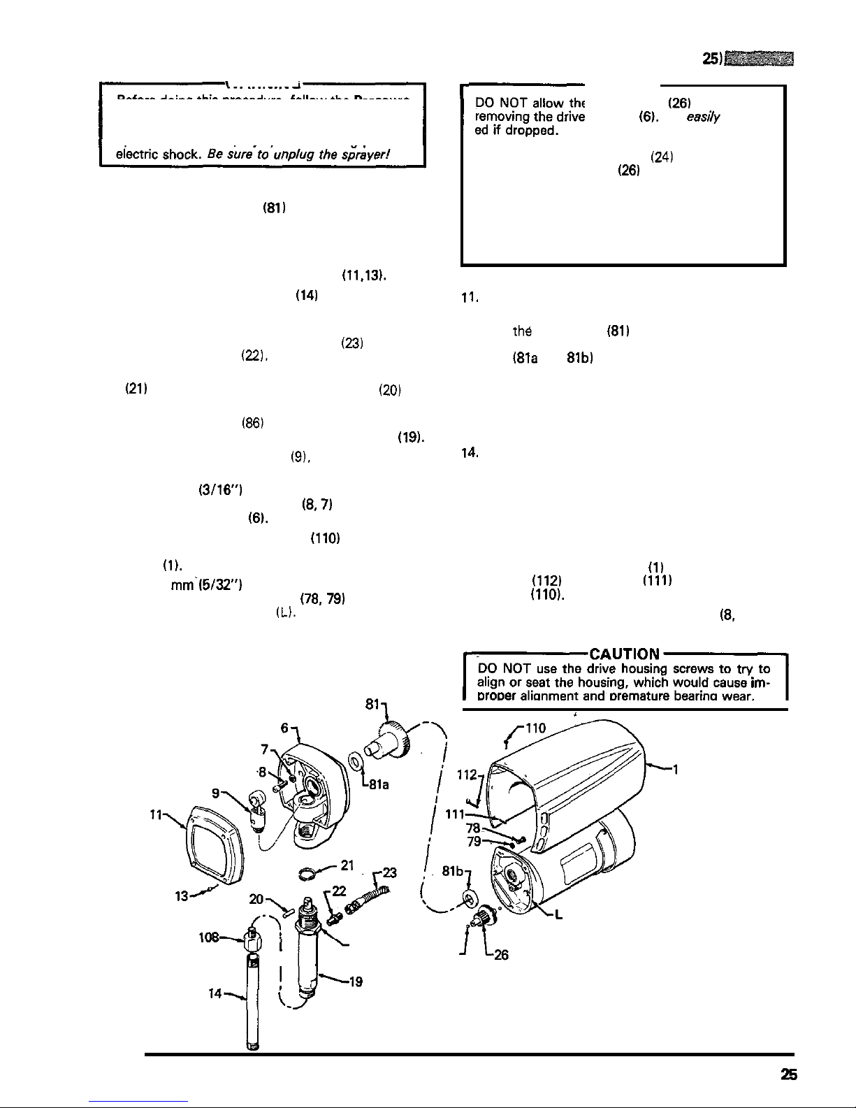
CONNECTING ROD, DRIVE HOUSING,
or
CRANKSHAFT REPLACEMENT
(See
Fig
25)
WARNING
Before doing
this
procedure, follow the Pressure
the risk of a fluid injection injury, splashing in the
Relief Procedure Warning on page
17
to reduce
eyes or on the skin, injury from moving parts or
NOTE:
Stop the sprayer at the bottom of its stroke
to get the crank
(81)
in
its lowest position. If
the crank must be lowered manually,
carefully rotate the blades of the fan with a
screwdriver.
1.
Remove the front cover and screws
(11.13).
2.
Unscrew the suction tube
(14)
from the pump,
the pump from loosening.
holding a wrench on the pump intake valve to keep
3.
Disconnect the pump outlet hose
(23)
from the
pump outlet nipple
(22).
4.
Use
a screwdriver
to
push aside the retaining spring
(21)
at the top of the pump. Push the pin
(20)
out
the rear.
5.
Loosen the jam nut
(86)
with an adjustable wrench.
Unscrew and remove the displacement pump
(19).
6.
Remove the connecting rod
(9).
inspect for wear or
damage, and replace if needed.
7.
Use a 5 mm
(3/16)
hex key wrench to remove the
three screws and lockwashers
(8.7)
from the recess
of the drive housing
(6).
8.
Remove the four short screws
(110)
and
two
long
screws
(1121
and spacers
(1111
from the motor
shield
(1).
Remove the shield.
9.
Use a 4 mm.(5/32") hex key wrench to remove the
two
screws and lockwashers
(78, 79)
from the top
rear of the front end bell (L).
10.
Lightly tap the lower rear of the drive housing with
a plastic mallet
to
loosen
it
from the motor front end
bell. Then pull the housing
off.
811
r-
CAUTION
DO
NOT allow the gear cluster
(26)
to fall when
removing the drive housing
(6).
It
is
easiiy
damag
-
ed if dropped.
DO
NOT lose the thrust balls
(24)
located
at
each
end of the gear cluster
(26)
or allow them to fall
between gears. The ball, which is heavily covered
with grease, usually stays
in
the shaft recesses,
and not removed, the balls
will
seriously damage
but could be dislodged. If caught between gears
the drive housing. If the balls are not
in
place, the
bearings will wear prematurely.
11.
Inspect the drive housing for wear or damage and
replace if needed.
12.
Pull the Crankshaft
(81)
out. Inspect for wear or
damage and replace, if needed. Be sure the bear
-
ings
i81a
and
81b)
are
in
place on either side of the
crankshaft assembly.
13.
Evenly lubricate the inside of the bronze bearing
in
the drive housing with high quality motor oil.
Liberally pack the roller bearings and gears
with
bearing grease.
14.
Install the crankshaft, meshing the gears.
15.
Clean the mating surfaces of the drive housing and
front end bell.
16.
Carefully align the drive housing and front end bell
with the locating pins, then push the drive housing
onto the front end bell or tap
it
into place with a
plastic mallet.
17.
Reinstall the motor shield
(1)
using the two long
screws
(112)
and spacers
(111)
and the four short
screws
(110).
18.
Install the screws and lockwashers
(8,
7)
and
tighten evenly.
ICAUTION1
DO
NOT use the drive housing screws to
try
to
align or seat the housing, which would cause
im-
DroDer alionment and Dremature bearina wear.
..
w
86
24
I
Fig
25
307-671
25
Page 27
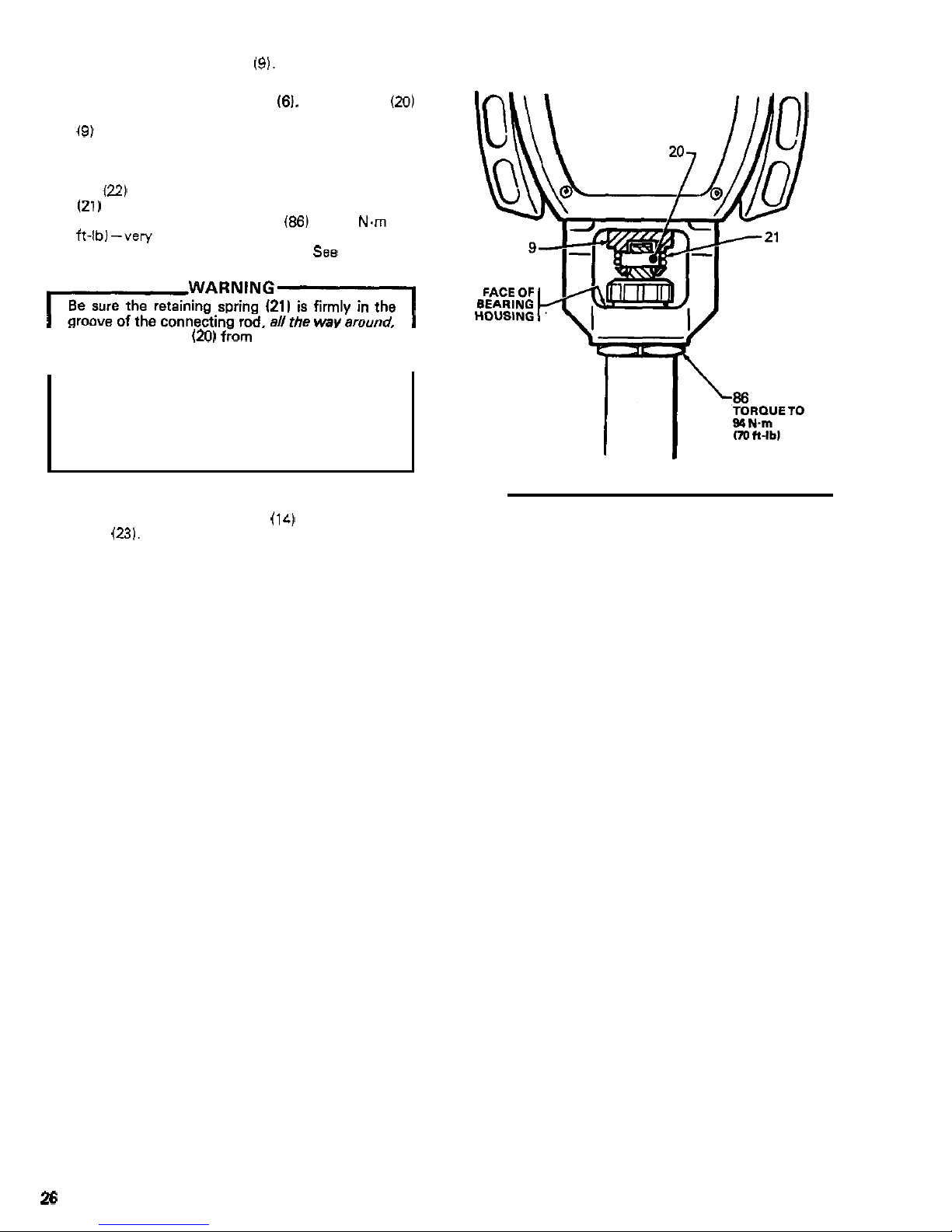
19. Install
the
connecting rod (9).
20.
Screw the displacement pump about 3/4 of the
way into the bearing housing
(6).
Hold the pin
(20)
up to the pin hole in the connecting rod assembly
(9) and continue screwing in the pump until the pin
slides easily into the hole. Back
off
the pump until
the top threads of the pump cylinder are flush with
the face of the bearing housing and the outlet nip-
ple
(22)
is
facing back. Push the retaining spring
(21)
into the groove
all
the way around the connect
-
ing rod. Tighten the jam nut
(86)
to
94
N.m
(70
ft-lb)-very tight to prevent
it
from loosening which
will damage the bearing housing.
See
Figures
25
and
26.
IwARN'NG1
Be sure the retaining spring
(21)
is firmly in the
groove of the connecting rod,
all
the
way
around,
I
io
prevent the pin
(20)
from working
loose
due
to
vibration. See Fig
26.
I
off
due to the force of
the pumping action.
These
If the pin works
loose,
it
or other parts could
break
parts could be projected through the air and result
in serious bodily injury or property damage, in
cluding damage to the pump, connecting rod or
bearing housing.
21.
Reinstall the front cover and screws
(11,
13).
Reconnect the suction tube
(14) and pump outlet
hose
(23).
Fig
26
26
307-671
Page 28
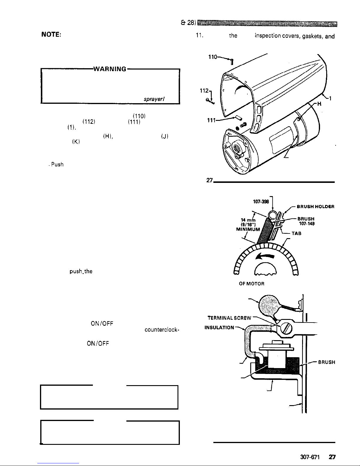
MOTOR
BRUSH
REPLACEMENT
(See Figs
27
8
28)
NOTE:
New motor brushes are included with each
11.
Reinstall the brush inspection covers, gaskets,
and
Packing Repair Kit. Replace them when screws. Reinstall the motor shield and screws.
replacing the packings, and/or when they
the longest side.
have been worn to a minimum of
9/16
on
Before doing this procedure, follow the Pressure
the risk of fluid injection injury, splashing
in
the
Relief Procedure Warning on page
17
to
reduce
eyes or on the skin, injury from moving parts or
electric shock.
Be sure
to
unplug the sprayer1
1.
Remove the four short screws
(110)
and the
two
long screws (112) and spacers
(111)
from the motor
shield
(1).
Remove the shield. See Fig 27.
2. Remove the screws
(HI,
inspection covers
(JI
and
gaskets
(K) on each side of the motor. See Fig 27.
3.
Loosen
the brush lead terminal screw and remove
the lead.
4.
.Push down on the spring clip slightly then pull the
clip away from and out
of
the brush holder. Refer to
Fig 28. Keep the spring clip.
5.
Remove and discard the brush.
J.K
Fig
n
6.
Inspect the commutator for excessive pitting, burn
-
NOTE:
A black color on the commutator is normal.
ing or gouging.
SPRING CLIP
107-398
7.
8.
9.
Have the commutator resurfaced by a
qualified motor repair shop if the brushes
seem to be wearing too fast.
edges are as shown in the first part of Fig
28,
and
Place a new brush
in
the holder
so
the beveled
the brush lead is routed as shown
in
the second part
of Fig 28.
the brush holder until the clip tab engages in the
Slowly
push.the tabbed end of the spring clip into
holder
and
the rolled portion of the tension spring
rests squarely on the brush.
Route the brush lead to the terminal and tighten the
terminal screws. Be sure the brush lead does not
touch any part of the armature or motor housing.
COMMUTATOR COMMUTATOR
SIDEVIEW
OFMOTOR BRUSH INSTALLATION
CAPACITOR
I
10.
Test the brushes:
TERMINALSCREW
a.
With the ON/OFF switch OFF, turn the
pressure control knob all the way
counterclock-
wise to minimum pressure. Plug
in
the sprayer.
b. Turn the
ON/OFF switch ON and slowly
in
-
crease the pressure until the motor comes up to
full speed.
c.
Inspect the brush and commutator contact area
for excessive arcing. Arcs should not
"
trail" or
circle around the commutator surface.
WARNING
Do
not touch the brushes, leads, springs or brush
BRUSH HOLDER
holders while the sprayer is plugged in
to
avoid
electric shock and possible serious bodily injury.
MOTOR END BELL
BRUSH LEAD
SPRING CLIP
-BRUSH
Do
not run the sprayer dry for more than
30
CAUTION
seconds while checking the brushes to avoid
damaging the displacement pump.
Fig
28
SHOWN WITH MOTOR LEAD
DETAIL OF MOTOR BRUSH
FACING BACK OF MOTOR
~
307-671
27
Page 29
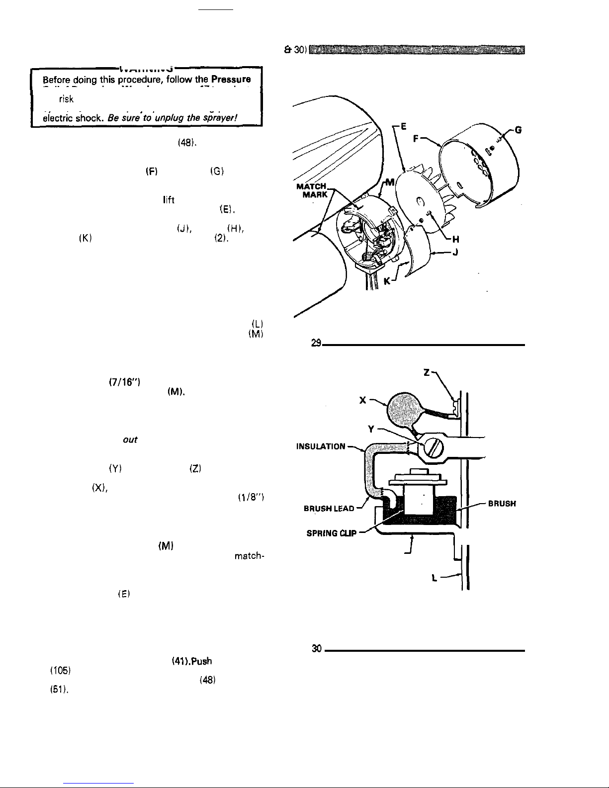
MOTOR CAPACITOR REPLACEMENT
(See
Figs
29
&
30)
WARNING
the risk of a fluid injection injury, splashing in the
Relief Procedure Warning on page 17 to reduce
eyes or on the skin, injury from moving parts or
1. Remove the control box cover
(48).
Disconnect the
motor leads.
2.
Remove the fan cover IF) and screws
(G)
from the
rear of the motor.
See
Fig
29.
3.
Use a screwdriver to
gently
lift the fan tab out of the
motor shaft groove and remove the fan
(El.
4.
Remove the inspection cover
(J),
screws
(H),
and
gasket
(K)
from each side
of
the motor
(2).
See
Fig
29.
5.
Push down slightly on the spring clip and pull the
clip out of the brush holder. See Fig
30.
6. Gently push the brushes out of the brush holder
and inspect. Replace if necessary.
See
page 27.
7. Make
a
matchmark between the front end
bell
(L)
and the motor housing and the rear end bell (M)
and the motor housing to use as alignment marks
of the motor housing. Refer to Fig
29.
during reassembly.
Also
make
a
mark on the
front
8.
Use
a
11
mm (7/16) socket wrench to remove the
nuts from the rear end bell
(MI.
9.
Gently
tap
alternate ears of the rear end bell with
a
plastic mallet to loosen
it,
then
pull
it
straight
off.
Do
not
pull the motor armature out.
Retain any
washers that fall
out
when the bell is
removed.
10.
To
replace
the
capacitor, remove the brush lead ter-
minal screws
(Y)
and the screw
(Z)
going into the
insulation plate of the rear end bell. Install
a
new
capacitor
(X),
making sure the ceramic case
of
the
capacitor
is
not cracked. Maintain
a
3
mm
(1/8")
clearance'between the capacitor and any grounded
same time.
metal parts. Always replace both capacitors at the
11. Position the rear end
bell
(MI over the
tie
bolts and
push
it
onto the motor housing. Align the metch-
nuts.
marks carefully and install the lockwashers and
12. Position the
fan
(E)
over the motor shaft and push
it
motor shaft groove.
into place, making sure the fan
tabs
engage
in
the
13.
Install the fan cover and screws.
14.
Reconnect the motor leads in the pressure control
box and reinstall the conduit
(41).Push conduit seal
(105)
into conduit elbow, around the motor lead.
Reinstall the pressure control cover
(48)
and screws
(51).
Fig
29
1
I
HOLDER
BRUSH
'4
Ll
SHOWN WITH MOTOR LEAD
DETAIL
OF
MOTOR
BRUSH
FACING BACK
OF
MOTOR
Fig
30
28
307-671
Page 30
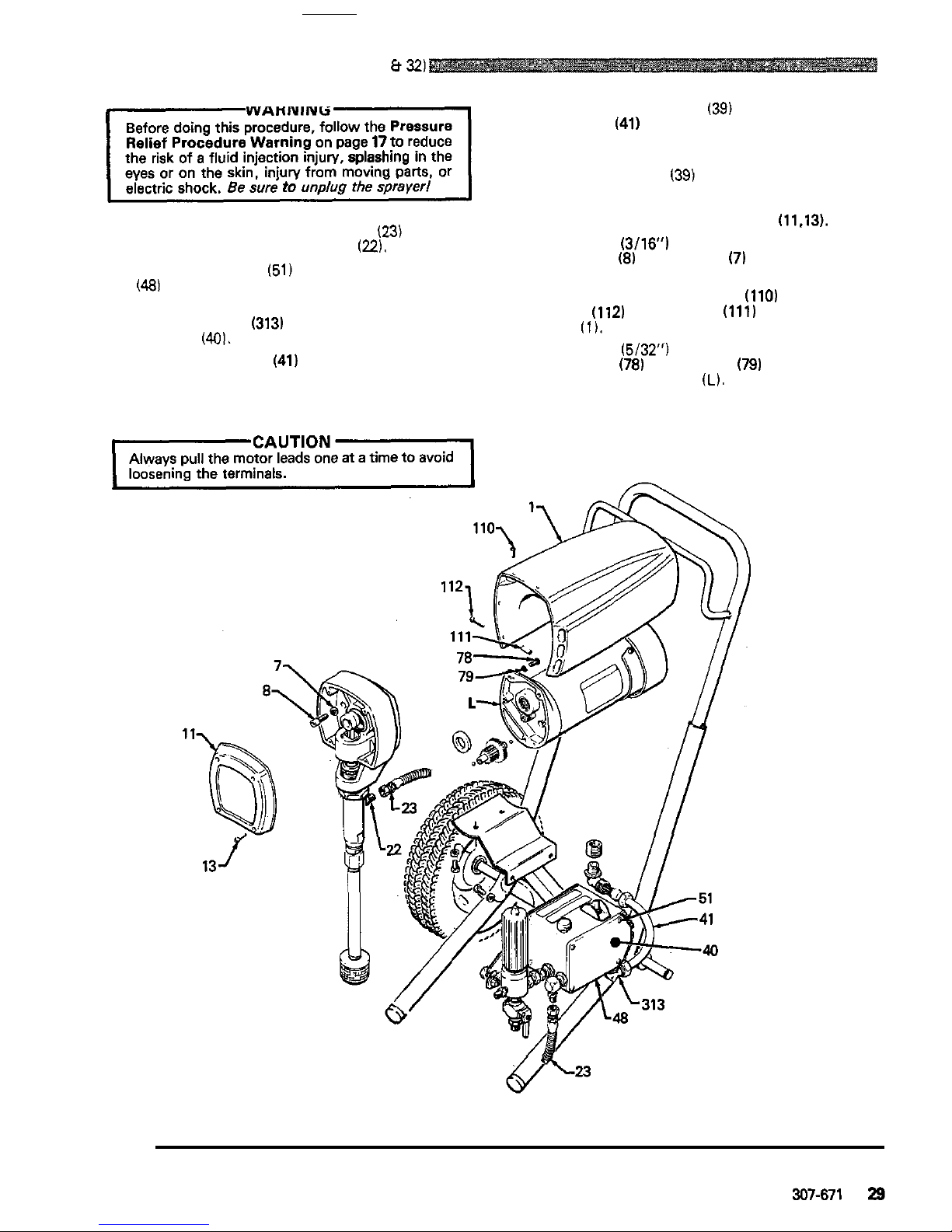
MOTOR
REPLACEMENT
(See Fig 31
8
32)
1
WARNING
Before doing this procedure, follow the Pressure
6.
Loosen the connector nut (39) at the motor and pull
the conduit
(41
away from the motor, then pull the
Relief Procedure Warning on page
17to
reduce
the risk of
a
fluid injection injury, splashmg in the
leads through the conduit, one
at
a
time. See Fig
31.
eyes or on the skin, injury from moving parts, or
electric shock.
Be
sure
to
unplug
the
sprayer!
7.
Unscrew the elbow
139)
from the motor.
8.
Pull the wires through the elbow,
one
at
a
time.
1. Disconnect the pump outlet hose
(23)
from the
displacement pump outlet nipple
(22).
2.
Remove the screws
(51)
and pressure control cover
(48)
and disconnect the four motor leads.
3.
Use
an adjustable wrench to loosen the conduit
connector nut
(313)
at
the pressure control
assembly
(401.
4.
Swing the conduit
(41)
away from the pressure
control elbow (313).
5.
Pull the motor leads through the elbow, one
at
a
time.
9.
10.
11.
12.
Remove the front cover and screws
(11.13).
two
screws
(8)
and washers
(7)
from the recess
of
Use
a
5
mm (3/16) hex key wrench to remove the
the drive housing.
screws
(112)
and spacers
(111)
from the motor
Remove the four short screws
(110)
and
two
long
shield
(1).
Remove the shield.
.
two
screws
(78)
and washers
(79)
from the rear of
Use
a 4 mm (5/32”) hex key wrench to remove the
the motor front end bell
(L).
Fig
31
Page 31
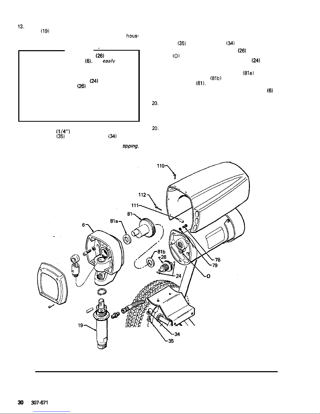
13.
Use a plastic mallet to gently tap the displacement
pump
(19)
from
the
rear to loosen the drive housing
ing away from the front end bell.
(6)
from the front end bell. Then pull the drive hous-
CAUTION
~
DO
NOT allow the gear cluster
(26)
to fall when
removing the drive housing
(6).
It
is easily damag-
ed if dropped. The cluster may stay engaged in
either the front end bell or the drive housing.
DO
NOT lose the thrust balls
(24)
located
at
each
end of the gear cluster
(261
or allow them to fall
with grease, usually stays in the gear recesses, but
between gears. The ball, which is heavily covered
could be dislodged.
If
caught between gears and
not removed, the balls will seriously damage the
drive housing. If the balls are not in place, the
bearings will wear prematurely.
14.
Use
a 6 mm
(114")
hex key wrench to remove the
two screws
(35)
and lockwashers
(34)
from the
underside
of
the motor mounting frame. Be
sure
to
support
the motor to keep the sprayer from
tlppmg.
15.
Lift the motor assembly
off
the frame.
16.
Place the new motor assembly on the frame and
align
-
with the frame mounting holes. Install the
screws
(351
and lockwashers
(34)
tightly.
17.
Liberally grease the gear cluster
(26)
and pinion
gear
(0)
and pack
all
bearings in the motor front
end bell. Check to be sure the thrust balls
(24)
are in
place.
18.
Be sure the bronze-colored bearing (81a1 and the
silver
-
colored bearing (81b) are properly placed on
the crank shaft
(81).
19.
Align the gears and push the drive housing
(6)
straight onto the front end bell and locating pins.
20.
Starting at Step
13
and working backwards, con-
tinue to reassemble the sprayer.
NOTE:
Use
a
turning motion on the conduit when
feeding wires through
it.
20.
Reinstall the motor shield and pressure control
cover.
Fig
32
Page 32

PART DRAWINGS
AND
PARTS LISTS
307-671
31
Page 33
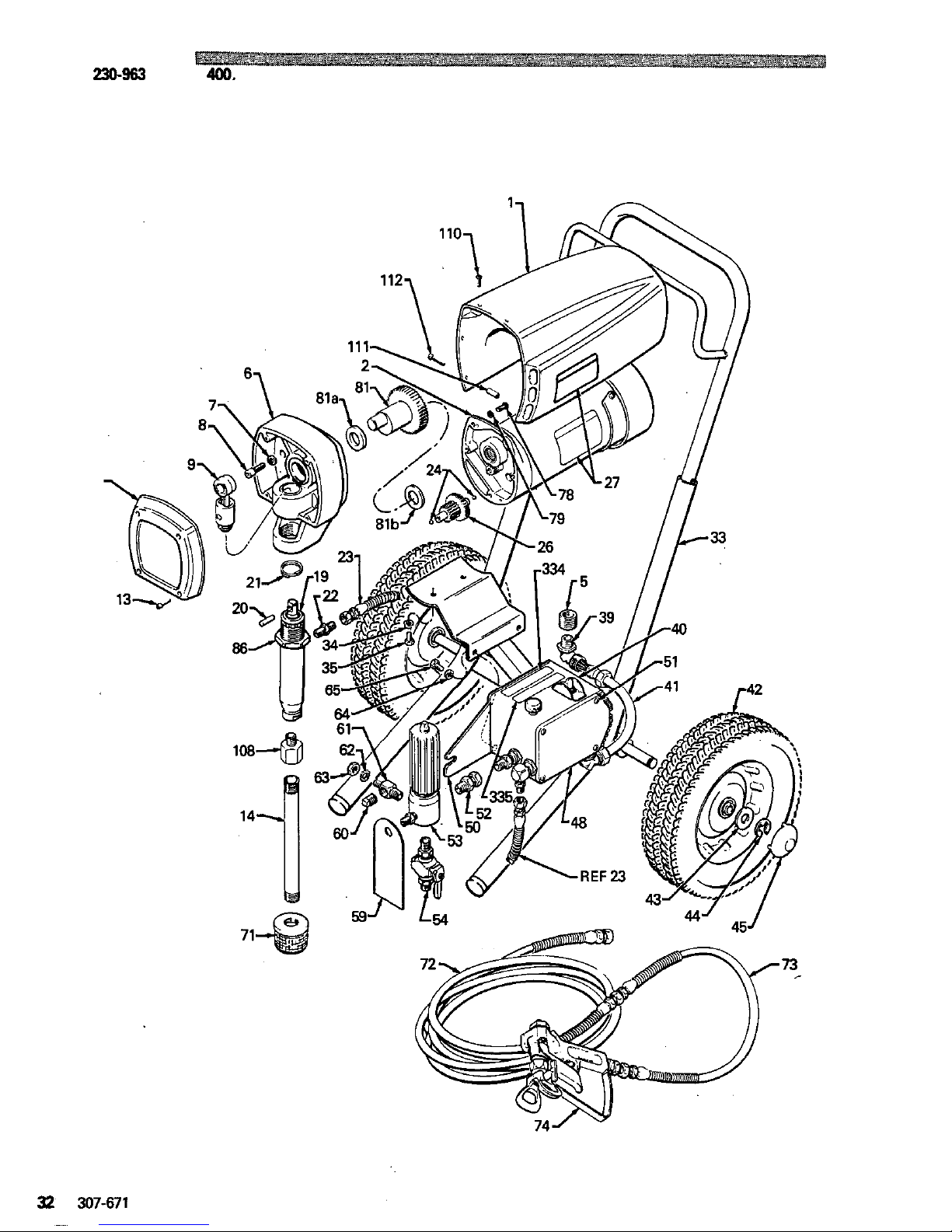
PARTS
DRAWING
Model
230-963
Ultra
"
400.
Series
D
Includes
items
1-112
11
Page 34
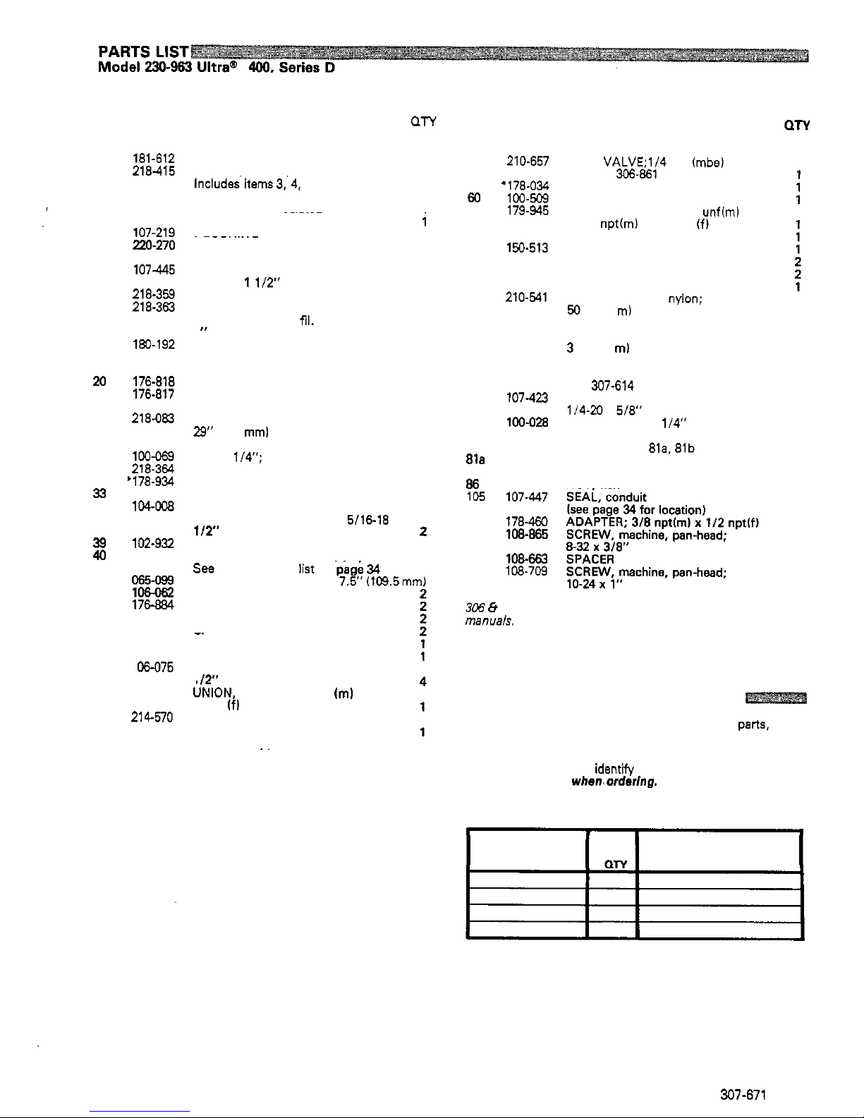
Includes
items
1-112
REF
PART
NO.
NO.
1
2
4
3
5
6
7
8
9
11
13
14
19
x)
22
21
23
24
26
27
33
34
35
39
40
41
42
43
44
45
48
50
51
52
53
218-415
181-612
107-267
107
-
264
220-270
107-219
105-510
107445
218-359
218-363
107-209
180-192
220-647
176-818
176-817
218-083
162-453
100-069
218-364
'178-934
218-361
104-008
107-212
102-932
218-353
065-099
106062
101-242
176884
104-81 1
218-326
179-936
1 OE-075
155-665
214-no
DESCRIPTION
QTY
SHIELD, motor
MOTOR, electric:
112
HP
1
Includesitems
3.4. 5,
one of item
24
and one of item
27
.
TERMINAL. insulated
1
1
.
TERMINAL; insulated
.
BUSHING
~~~~~~
i
1
HOUSING, drive
LOCKWASHER;
114
"
1
SCREW, cap, socket-head;
3
1/4-23
x
1
1/2"
CONNECTING ROD ASSEMBLY
3
COVER, drive housing
1
SCREW, machine,
fil.
head;
8-32
x
1
TUBE, siphon
1
"
4
1
PUMP, displacement
Refer to
307-793
for parts
1
PIN, straight, headless
SPRING, retaining
1
NIPPLE;
114
npsm x
1/4
npt
1
1
HOSE; grounded, nylon;
114
"
ID;
29"
(736
mml
long;
spring guard
both ends
BALL;
1/4";
SST
GEAR CLUSTER
LABEL, warning
CART FRAME
LOCKWASHER;
5/16
SCREW, cap, socket-head;
5\16-18
x
~~
1
2
1
2
1
2
<
,^..
-
CONNECTOR, conduit
IIL
z
PRESSURECONTROLASSY:
1
see
separate parts list on page
34
CONDUIT, electrical
1
7.5'1109.5mm1
WHEEL
WASHER, back
-
up
RING, retaining
CAP
huh
COVER, pressure control
BRACKET, mounting
SCREW, thread
-
forming;
10-24
x
-. . . , . .
"
1
I?"
UiION, adapter;
318
npt
(m)
x
318
npsm
If1
swivel
FILTER,
fluid
Refer to
307-273
for
parts
..
REF
PART
NO. NO.
54
60
59
61
62
63
64
71
65
72
73
74
78
79
81
81a
81
b
86
105
108
110
111
112
210-657
+178-034
100-509
179-945
100-322
150-513
100-214
100-001
210-541
181-073
214
-
701
220-955
107-423
100-028
218-242
180
-
131
107-434
176-762
107-447
178483
108-865
108-663
108-709
DESCRIPTION
BALL
VALVE;1/4 npt Imbe)
Refer to
306.861
for parts
TAG, warning
PLUG, pipe
ADAPTER, elbow;
7/16
unflml
WASHER;
7/16
x
114
npt(m) x
114
npt
1fl
NUT, jam. hex;
7/16
"
LOCKWASHER;
5/16'
SCREW, cap, hex;
5/16-18 x 518
"
STRAINER
HOSE, grounded,
nyion;
114
"
ID;
50
ft
115
m) long; spring guard both
ends
HOSE, grounded. nylon;
3/16'
ID;
3
ft
(0.9
ml
long; spring guard both
ends
GUN, airless, contractor;
SCREW, cap, button head;
See
307-614
for parts
LOCKWASHER;
1/4"
114.23 x 5/8"
CRANKSHAFT ASSEMBLY
Includes items
81a.
81b
.
BEARING
.
BEARING
NUT. hex
1
1
1
2
2
1
1
1
1
1
1
4
2
2
306
e
307
numbers
in
descriptions refer
to
separate instruction
manuals.
'Warning labels and tags supplied at no charge.
HOW
TO ORDER REPLACEMENT PARTS
1.
To be sure you receive the correct replacement parts, kit or
accessories, always give all of the information requested in
the chart below.
2.
Check the parts list
to
identih, the correct part number;
do
not
use
the
ref.
no.
when,ordering.
3.
Order all parts from your nearest Graco distributor.
6
digit
PART
NUMBER
PART
DESCRIPTION
307-671
33
Page 35
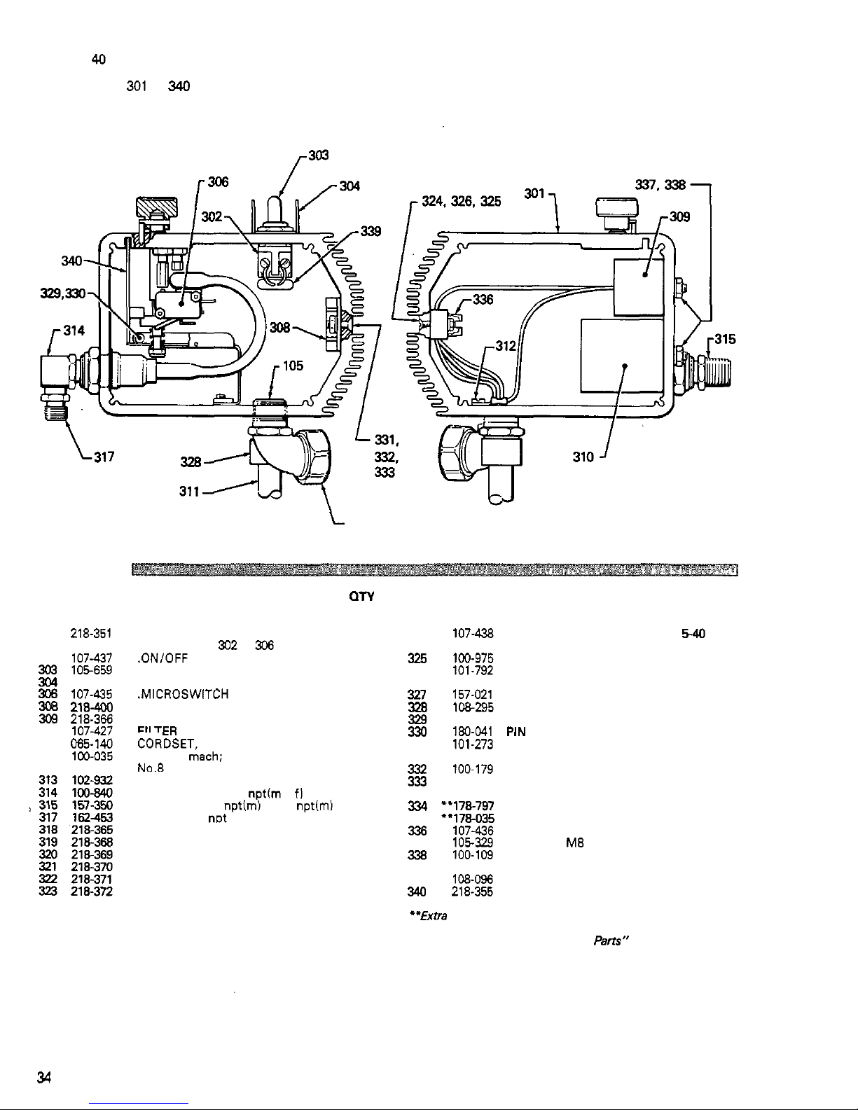
Ref
No.
40
Includes items
301
to
340
PRESSURE
CONTROL ASSEMBLY
313
PARTS
LIST
REF PART
NO.
NO.
301 218-351
302
107-437
303
105659
304
107-255
306
107-435
3B
218-400
309
218-366
310 107427
311
065-140
312
100-035
DESCRIPTION
BARE
PRESSURE
CONTROL
BOX
Includes items
302
to
306
.ON/OFF SWITCH
.BOOT, ONIOFF switch
.GUARD, locking
.MICROSWITCH
BRIDGE, rectifier, SCR
CHOKE
FII
TEE)
.
...
,
..,.
CORDSET, power supply; no plug
SCREW,
mach; slotted pan head;
No.8
x
5/16
"
CONNECTOR, conduit
ELBOW. street;
1/4
npth x fl
ADAPTER,
3/8
npttrn)
x
1/4
nptlm)
NIPPLE.
114
nDt
.
. . .
.
.
.
.
.
.
HARNESS
, wire
HARNESS, wire
HARNESS, wire
HARNESS,
wire
HARNESS,
wire
HARNESS,
wire
ON
1
1
1
1
1
1
'1
1
1
1
1
1
1
1
1
1
1
1
1
1
REF PART DESCRIPTION
NO.
NO.
324 107-438
SCREW. machine.
fil
head: No.
5-40
325
326
327
328
329
331
330
332
333
334
335
337
336
338
339
340
100-975
101.792
157-021
108295
107-258
180-041
101-273
100-179
100-718
107-436
105329
100-109
218-355
1080%
x
518
"
long
NUT, hex, machine,
No.
5
shakeproof; No.
5
LOCKWASHER, external,
BUSHING, strain relief
LOCKWASHER, No.
8,
internal
TIP, pin, black plastic
.
Dlhl
I I,"
SCREW, machine, flat head;
No.
10-24 x 518
"
long
NUT, hex, mscr, No.
10-24
thd
LOCKWASHER, internal, shakeproof;
No.
10
LABEL. WARNING
TERMINAL STRIP
LABEL, WARNING
NUT, hex,
M8 x
1.25
LOCKWASHER, external,
shakeproof;
5/16
VARISTOR
CIRCUIT BOARD
QTY
2
2
2
1
1
1
1
2
2
2
1
1
1
2
2
1
1
**Extra Warning labels and tags supplied at
no
charge.
See
'How
To
Order Replacement
Pam"
on page
3.
34
307-671
Page 36
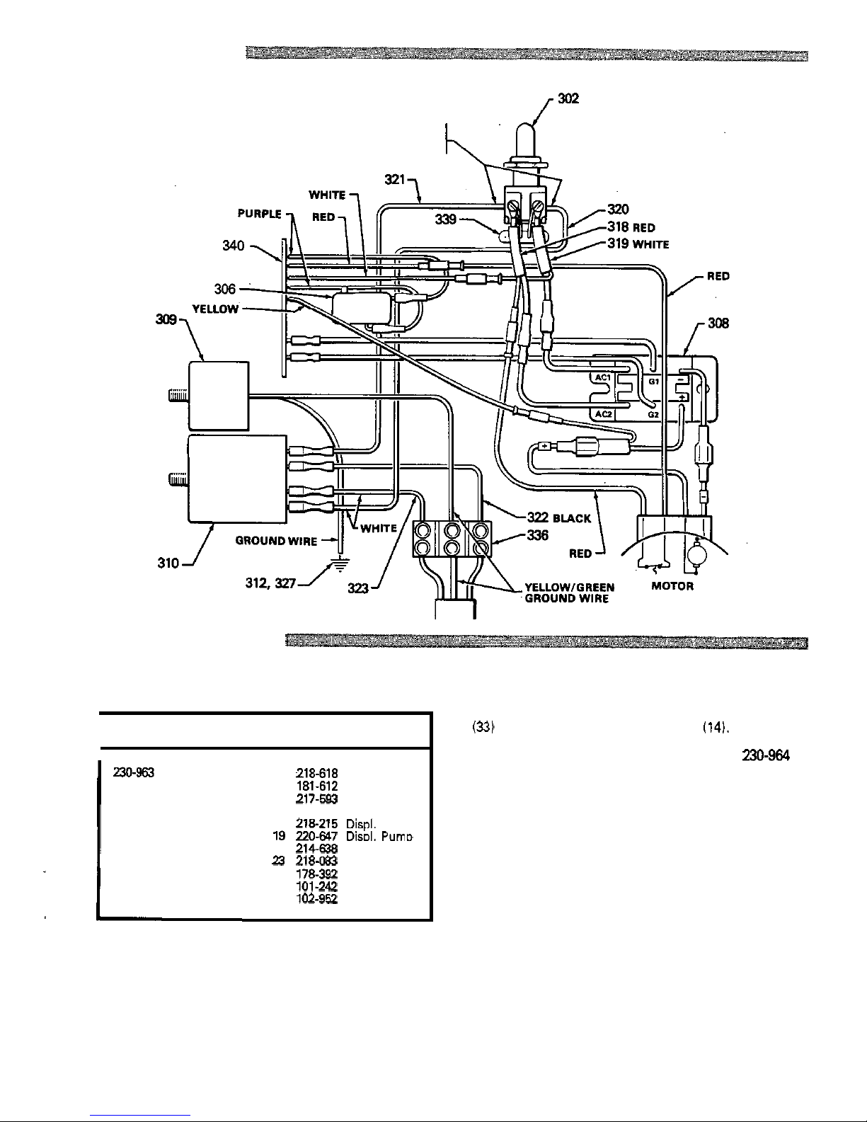
WIRING DIAGRAM
TO
TWO
TERMINALS ON THE OTHER
THESE WIRES ARE CONNECTED
SIDE
OF
THE
ONlOFF
SWITCH
SERVICE
INFORMATION
Listed below by the assembly changed are
OLD
and
NEW
parts.
NOTE:
This manual now includes complete service
procedures. The parts list has new reference numbers.
ASSEMBLY PART
REF PART
CHANGED STATUS
NO. NO. NAME
Sprayer,
Series
OLD
OLD
NEW
NEW
OLD
OLD
NEW
OLD
NEW
OLD
NEW
NEW
14
218-618
Motor Cover
1 181-612
Motor Shield
74
220-955
Gun
16 217-593
Gun
39
218-215
Displ.
Pump
19 220-647
DisDl.
PUmD
47
214-638
Hose
23
218-083
Hose
58
178-392
Pin
135
102-952
Strainer
44
101-242
Ring
71
181
-
073
Strainer
Other major changes to the sprayer are the upright cart
(33)
and changes to the suction tube
(14).
DISCONTINUED MODEL
NOTE:
Model
230-964
is
obsolete and has been deleted from the manual.
307-671
35
Page 37
ULTRA@
400
TECHNICAL
DATA
Power Requirements
:
230
VAC,
50
Hz,
1
Phase,
3.7
AMP minimum
CyclesILiter (gallon)
:
124
(470)
Operating Range
:
0-192
bar
(0-2750
psi)
Power Cord
:
2.5
mm 0 (13
ga.), 3 wire,
6 m (20
ft)
long
Inlet Paint Strainer
:
16
mesh,
1190
micron,
Outlet Paint Filter
:
60
mesh,
250
micron,
Stainless Steel Screen, reusable
Stainless Steel screen, reusable
Fluid Outlet Size
:
114
npsm from fluid filter
Pump Inlet Size
:
314
npt w/30° I.D. chamfer
Weight
:
36
Kg
(80
Ib) approximately
Wetted Parts : Aluminum, Delrin@ , Nitralloy, Nylon, Ultra-High
Molecular Weight Polyethylene, Polyurethane, Rubber
Tungsten Carbide, Zinc
-
plated steel
impregnated leather, Stainless Steel,
,
Height: Handle extended:
939.8
mm
(37
in.)
Length: Handle extended:
660.4
rnrn
(26
in.)
Dimensions : Width:
546.1 mm (21.5
in.)
Handle down:
723.9
mm
(28.5
in.)
Handle down:
609.6
mm
(24
in.)
Delrin' and are registered trademarks
of
the Du Pont Company.
Subsidby
and
ARlbte
Canpanles:Canada; England;
Switzerland
France; Germany;
Hong
Kong; Japan
Factory
Ernnc~.Atlente.
Dallas,
Datrolt.
Loa
Angala.
Wat
Csldwall
lN.J.1
GRACO
INC.
P.
0.
Box
1441
MINNEAPOLIS, MN
55440-1444
PRINTED
IN
U.S.A.
307811 1-84
ReViSed
7-87
PTFE
PTFE
PTFE
PTFE
PTFE
PTFE
 Loading...