

Page 1
INSTRUCTIONS AND PARTS LIST
10
GALLON
STATIONARY MODEL
LESS WHEELS AND SRAKC
WITH MANUAL ELEVATOR
226-161 SERIES "A"
HAS MANIFOLD
WITH DUMP VALVE
PRESIDENT
WITH MANUAL ELEVATOR
226-163 SERIES"A"
HAS MANIFOLD
WITH DUMP VALVE
HYDRA-SPRAY
PORTABLE MODELS
WITH PNEUMATIC ELEVATOR
226-165 S£R1ES"A"
HAS FILTER
WITH DUMP VALVE
UNITS
226-167 SERtES"A"
HAS FILTER WITH DUMP
VALVE AND SURGE TANK
FORM:306-704
PUBL.SH£D: /-£/
TIP OF
CUSTOMERS CHOICE
r*
~ N.BT.
^ AIR INLET
MANUAL
ELEVATOR
I5“FT.
HOSE
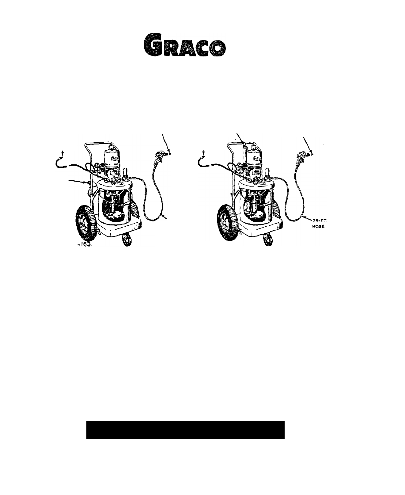
MODEL 226
ILLUSTRATED
DESCRIPTION
These Hydra-Spray Units apply light materi
als by utilizing HI&H HYDRAULIC PRESSURE THROUGH
A SMALL FLUID ORIFICE. The combination of high
fluid pressure and small orifice creates fine
material breakup without atomizing air. This
airless spraying system without heat was origi
nally pioneered and developed by Graco engineers
to improve the consistency and lower the costs
of coating applications. The portable, truckmounted Hydra-Spray units wheel directly to the
work, wherever the job site...in-plant or out
side, on rough terrain or in a remote area.
Works direct from original 1 to 10 gallon con
tainers. Provides fast color changing for short
run work, quick mobility for constant one-color
application.
Units utilize air press\ire to (l) operate
the pump which powers the transfer of material
to the spray tip, (2) drive the agitator that
thoroughly mixes and keeps material solids in
sprayable suspension and (3) power the pneu
matic elevator, of Models 226-165 and 226-167,
for fast, easy material container changing. No
air used to atomize the material...no pressure
on container...no possible aeration of material.
Special, air-powered, reciprocating type pump
PNEUMATIC
ELEVATOR
I"
^N.RT.
AIR INLET
MODEL 226-165
ILLUSTRATED
provides continuous-duty action, ’.dth equal pres
sure and volume delivery on both strokes. Pump
develops material pressure 28 times greeter than
the inbound air pressure. (For example: at 60 PSl
inbound air, the pump develops 1680 PSI material
pressure.)
Units are designed for high volumeprod
uction-type spraying of protective coating paints
and similar light materials, providing a heavy,
one coat application with almost complete elimi
nation of overspray. All units are equipped with
a material outlet manifold having a valve > for re
circulating material or dumping sludge. -.Also
manifold has an exrtra material outlet for addition
of a second spray gun. Models 226-165 and 226-167
include a filter kit, shipped loose, which can be
easily installed in manifold to filter the materi
al. Also Model 226-167 includes a surge tank,
shipped loose, that can be easily assembled to
manifold to eliminate material surge. NOTE: A
tungsten carbide spray tip of customers choice is
included in all units. The proper spray tip to be
used for a specific material should be detennined
by a test conducted by your local Graco Industrial
Distributor or by his recommendation from previous
experience with the same or similar material.
TIP OF
CUSTOMERS CHOICE
7
RETAlNlFOlii-UtU^REFERENtE
• MINNEAPOLIS T3, MINN.
facterji anuKha; NEW YORK {Loa| Iilind Citri, PHILADELPHIA. DETROIT. CHICAGO. ATLANTA, SAN FRANCISCO, HOUSTON "
Page 2
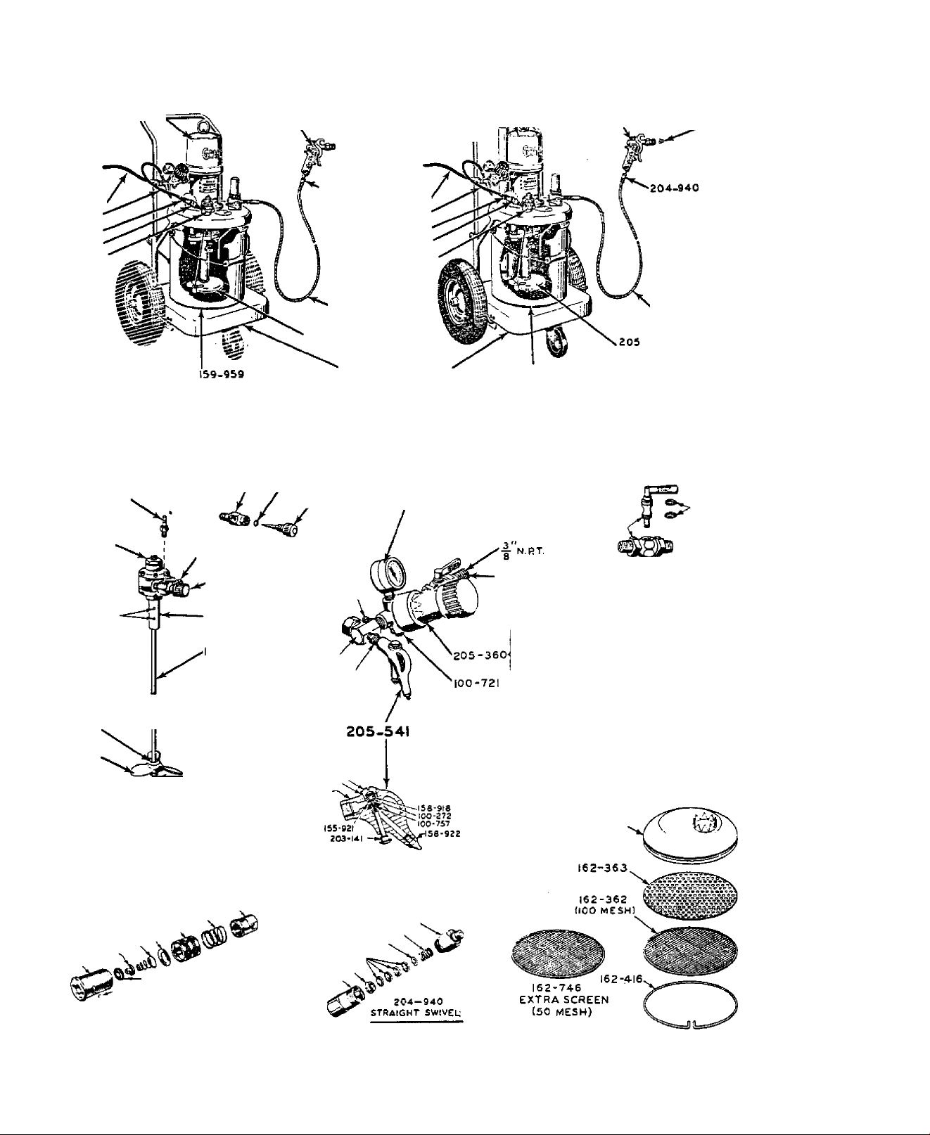
205-434 2S-I PUMP
f FOR BAHTS
\^epAHATE SHEET^
205-162
SPRAY GUN
f FOR PARTS see'.
I^sepahate sheets
TIP Of
customers
CHOICE
/
205-434 Z8-1 PUMP
(''for parts s-:e'\
Uepabate eheet_J
205-162
SPRAY GUN
( FOR PARTS SEE>
^separate sheev
TIP OF
CUSTOMERS
CHOICE
205-216
160-023
100-030
202-437
205-307
agitator
MODEL 236-161 SERIES "A"
(stationary less wheels and brake)
MODEL 2 26- 163 SERIES "A"
(with manual elevator)
157-367
101-687
100-002
I6I-4IS j,
205.526
161-411
64-179
STRAINER
164.700
/ 157-628
162-376
204-940
205-349
lISFT.l
205-306
205-507
100-403
151-519
205-216
160-023
100-030
202-437
205-307
agitator
TRUCK AND
elevator GROUP
101-180
STRAINER
159-959
MODEL 226-165 SERIES "A‘
MODEL 226-167 SERIES "A‘
(with PNEUMATIC elevator)
202-340
202-338-
FOR parts
SEE
SEPARATE
SHEET
202-338
AIR LINE PETCOCK
204-938
125 FT)
306
——157-244
___
157-245
M
----
137-241
^
----
101-02 I
160-015
y
I0I-I9S'
161-413
IS7-4S9
205 -307
AGITATOR
157-467
IS7-560
157-470
157-469
-157-558
-157-559
'■^157-460 202-437
AIR LINE COUPLER
100-346
100-133
IS7-S57
157-471
156-917
150-451 ‘
158-921
AIR BLOWER VALVE
I62-6S4,
157-894^
204-978-
150-522 ,
ISO-516 ■
tOI-368
164-170
157-898,
205-306
STRAINER
Page 3
164-346
)57-eea
IS9-9a4
K a
AIR ELEVATOR
FOR MODELS 226-165
AND 226-167
g
^100-077
Si.
203-666
FOR MODELS 226-161
AND 226-163
100-214
100-077
I00-S38
100-214
205-497-
100-188
100-214
205-476
SURGE TANK
FOR MODEL
226-167
(SHIPPED LOOSE''
205 485 r‘’ARTS SEE
^°^"^^\^SEPABATE SHEEtJ
162-344
2Ö5-52’3
filter kit
FOR MODELS
226-165 t 226-167
(SHIPPED LOOSE)
101-706
31-706
lot-704
101-705
TRUCK
AND
ELEVATOR
GROUP
Page 4

This equipment has been carefully manufac
tured to exacting CHACO standards. It is war
ranted against defective materials and/or work
manship as set forth in the GRACO WARRANTT.
Excessive wear due to passage of abrasive or
corrosive materials through this equipment shall
not be construed as indication of defective parts
within the limitations of this warranty.
IMPORTANT NOTES
•*PTFE * material hose is expensive. HAHPLE
WITH Cakjs. GRACO WARRANTY does not cover abuse
such as sharp kinking, crimping or crushing.
Air supply hose 205-216 includes a static
wire to effectively ground the unit. If addi
tional air supply hose is required, it should
be of the same type.
PREPARATION FOR OPERATION
1, Remove contents from carton and connect
the wire-braided Dupont ’’PTFE*’ lined material
hose 205-3A9 (15') or 20A-yja ^25’) to nipple
161-672 protnidtng from material outlet manifold
205-485. Connect the end, without swivel 204-940
attached, to nipple 164-672. See Fig. 1. DO NOT
connect swivel 204-940, attached to other end of
this hose, to spray gun at this time. DO NOT USE
THREAD SEALER AT ANY SWIVEL CONNECTION.
AIR REQUIREMENTS
Air pressures required to operate pump range
from 20 to 100 p.s.i. CAUTION; Do not use more
than 100 lb. of air pressure to operate pump.
During continuous operation, at norTnal work
ing pressures and operating speeds, this unit will
reqviire actual air delivery of approximatelY ^
c.f.m. per gun plus 3 c.f.m. for continuous use of
agitator.
To provide reserve capacity for peak load
conditions compressor shovdd delivery 25% more air
than required for normal operation of all equip
ment vdiich It is to serve.
NOTE; Consumption of compressed air Is low.
since in this Hydra-Spray process air is not need
ed to atomise the paint.
before reaching unit. NOTE; A Graco air line
strainer 204-999 (accessory) may be purchased
separately for removing foreign matter from air
entering the unit. Attaches to air manifold
162-376 as shown in Fig. 2.
,205-216--^VpT
157-367
THESE ARE accessories
202-338
'^^^^205-360
104-038 125
FIG. I 305-307
HORIZONTAL (CLOSED».
NOTE: Check dump valve of manifold 205-485
...it should be closed. When closed, its knob
is in a horizontal position. Refer to Fig. 1.
2. For operation of a second spray gun
purchase these accessories separately...two (2)
high pressure material shutoff valves 205-583,
a second hose 205-349 (15') 204-938 (25*), a
second swivel 204-940, a second spray gun 205-162
and a second spray tip of customers choice. Re
move nipple 164-672 and plug from manifold
205-485, and qormect valves and hoses as shown
in Fig. 2. ' '
3. Attach one end of 15 foot air supply hose
205-216 to soiH-ce of air supply and screw other
end of hose into air manifold swivel adapter
162-376.'' Refer to Fig. 1. Male hose studs are
threaded ^ NPT. Install a master air valve
(drain or bleed type)in the air supply line in
such location that air can be turned on and off
OR
05-349115
205-583
NOTE: Models 226-163. 226-165 & 226-167 are
equipped with a brake—to set brakes push down
with foot on rod protruding from bracket attached
to back of truck base and guide rod into notch at
bottom of bracket.
4. If Model 226-161 or 226-163 with hand
operated elevator, lift up on elevator hanger and
hook over handle. NOTE: If elevator is difficult
to raise, apply a little grease to exterior svirfaces of handle ends.
If Model 226-165 or 226-I67 with air-operated
elevator. disconnect air line coupler 202-437,
attached to end of air hose 160-023, from air line
fitting in agitator 205-307 and connect to air
line fitting 157-367 atop elevator as shown in Fig.
1, With air admitted to unit, elevator will raise
unit and hold it there until air hose 160-023 Ls
disconnected. '
Page 5

5. Remove from base the 10 gallon pail pro
vided. Wipe clean its interior and potiT into it
material stirred and thinned to the proper sprayconsistency or place a smaller container of ma
terial inside the 10 gallon pail. Stir material
thoroughly making sure there is no heavy pigment
concentration or cake formed on the bottom of the
container* The pigments must be well dispersed to
prevent them from clogging the fluid intake
strainer 205-306 v4ien the pump is initially lower
ed into the container of material.
ROTBs For a small container, such as a one
gallon can, the material intake strainer must be
removed in order to get the lower pump housing and
the agitator propeller into the container.
6. Check the position of foot valve feet in
relation to the perforated plate 162-363 of pump
fluid intake strainer. When the plate and screen
are held in position by the retaining ring 162-416,
the feet of foot valve body must contact and sup
port the perforated plate 162-363 as shown in
Fig. 3*
should be used with spray tips having larger ori
fice openings.
7* Lower pump into material. If unit with
manual elevator, unhook hanger to lower. If unit
with pneumatle elevator, lower by disconnecting
air hose 160-023 from elevator air line fitting*
Refer to Fig. 1*
NOTE; The speed at which unit is elevated^
bv air, is set at factory. If adjustment is
necessary, loosen lock nut of air restrictor
valve 203-743 and turn restrictor screw clockwise
to decrease or cqunterolo^kwi^e to increase * Lock
screw in place with lock nut when adjustment is
completed. Air.restrictor valve 203-743 is locat
ed atop elevator tube. Refer to Fig. 1.
8, If unit includes a filter kit 205-523 or
a filter kit 205-523 and a surge taniT 205-4767
refer to illustrated instructions in separate
Form 306-696 for easy conversion of manifold
205-485 to a filter or a filter-surge chaaiber. .
9- Insert delivery end of material dispens
ing hose into a xiraste container. Start pump by
opening CM-OFF punro air petcock 202-338 and set
ting regulator 205-360 at 30 p.s.i. Refer Fig. I.
Allow pimip to operate until all traces of rust
inhibiting oil, with vrfiich pump was treated, is
removed. Stop pump and discard material pumped.
NOTE: If desired, the 100 mesh screen in
strainer 205-306 can be removed and replaced -with
the extra, more coarse 50 mesh screen 162-746 sup
plied. Refer to Fig. 3- This 50 mesh screen
IMPORTANT NOTES
1. For most satisfactory operating condi
tions, locate pump and material so that they will
not be subjected to temperatures below 65° F.
2. Do no.t attempt to spray materials con
taining hea-gy fillers, dirt or other coarse
particles> Coarse grind, coagulated, con-taminated and skinned materials that will not pass freely
through the openings in sice of screen or filters
being used, without clogging, can not be satis
factorily sprayed. Due to the extremely small
orifice diameter in spray tip through vdiich ma
terial must be forced under pressure, it is very
Impor-bant that particle's which could plug this
orifice are not present in the material to be
sprayed.
3. Daily, before starting to spray, remove
and clean filter, if used, of spray gun.
Paily. with air pressure shut off and
relieved, remove and clean screen in air line
s-fcrainer 204-999 (accessory), if used. Add
light oil to screen cavity in strainer nut. See
Fig. 4.
NOTE: If accessories have been added to
-unit for two gun operation, open material shutoff
valves 205-583 and insert ends of both hoses Into
-waste container before starting pump. Refer to
Fig. 2.
10. Connect swivel 204-940, at-tached to free
end of material dispensing hose, to spray gun
inlet.
OPERATION
5.. Dally or more often if experience indi
cates necessary. WITH PUMP DEACTIVATED AMD FILTER
DUMP VALVE OPEN TO RELIEVE MATERIAL PRESSURE, re
move and clean filter cartridge or screen, if
used. Refer to Fig. 1.
6. Dally, remove and clean screen in pump
material intake strainer 205-306. When replacing,
check to be sure that plate 162-363 is in contact
with feet of pwmp foot -valve. Refer to Fig. 3
7* When thinning material;cleaning filters,
screen, tips, etc.; changing types of material to
be sprayed or flushing unit; be sure to tise CLEAN
solvent of a type recommended b.y manufacturer of
material being sprayed. Use of the wrong solvent
may cause jelling or separation, of material oompo-
ents which could cause clogging of strainer,
filter and spray gun tip. DO NOT USE COMMON GUN
CLEANER.
Page 6

НОТЕ: If manufacturer of material does not reommend a specific type of solvent, check the comatability of the solvent to-be used for thinning
he material by dropping a single drop of the materi1 into a small container of the solvent. If the
laterial drop clouds or disperses readily, the sol-
■ent is compatible. If drop tends to string or
orm a ball, the solvent is not compatible and
.efinitely should not be used. •
AGITATION OF MATERIAL
Thorough agitation of material should be
lecomplished prior to Dumping material to spray
Agitation can best be obtained as follows ;
am
1. Snap air line coiçler 202-437 onto agi:ator air fitting and agitator will be energised,
lefer to Fig. 1.
2. Turn agitator air valve 205-528, two or
nore turns to the left to start agitator air
notor. Refer to Fig. 1. Speed of agitation
nay be adjusted to suit the particular viscosity
3f material used. NOTE: Excessive agitation
speed may cause vibration and foaming of material,
dse moderate agitation speeds at all times.
3. Open manifold dung) valve and start pump.
This permits pump circulate the material under
light load.
4" Lift hinged inspection plate and examine
progress of agitation through hole in cover. It
is extr^^maly impcirtant that all solids are put in
suspension and held there dbring the entire spray
operation.
5. Allow agitator to continuev operation .
hüe unit is supplying material to spray gun.
SUPPLYING MATERIAL TO GUN
1. Stop puag) and close manifold dump valve
iter material has been circulated sufficiently
jid before attempting to spray. When closed,
ïiob of dump valve is in a horizontal position.
inbound air pressure. Do not set higher than
100 p.B.i.
5- While spraying be sure at all times to
hold spray gun perpendicular (approx. 90“) to '
surface to be sprayed, with its spray tip 12 to
14 inches from surface or greater if the material
spray will cover satisfactorily. NOTE: Good
Hydra-Spray technique is very similar to con
ventional spraying with air, except for the
greater distance spray tip should be held from
work surface, the larger coating thickness pro
duced which results in less pattern overlapping
and the positive action used vdien triggering gun.
NOTE: Refer to the SERVICE DIAGNOSIS CHART
in this Instruction Sheet for assistance in lo
cating troubles which may occur during spraying.
Also refer to separate Instruction Sheets for
specific information pertaining to the spray gun,
pump, regulator and manifold or filter.
SAFETY PRECAUTIONS
The Ifydra-Spray equipment develops extremely
high material pressure which remains in the system
until relieved by shutting off the air to pump
and releasing the material pressure by opening
manifold dump valve. In operation, if the fine
high pressure stream of material released from
spray gun is allowed to come in direct contact
with the hand or any part of human body it could
penetrate the skin and cause physical harm.
HANDLE THE HYDRA-SPRAY GUN AS CAPTIOUSLY AS
YOU WOULD ANY GUN: LOADED CR UNLOADED. The fol
lowing safety precautions should be observed;
Never point gun directly at the face.
Never put the hand or fingers directly over
the spray tip. (Use of protective leather gloves
is recommended.)
Never place the tip or gun nozzle directly
in contact with any part of the body.
2. Open material shutoff valves 205-583
accessory), if used. Handles are parallel to
■alve body when open. Refer to Fig. 2*
3. Open ON-OFF pump air control petcock
102-338. With petcock open, manifold dump valve
losed and air regulator 205-360 set to control
ihe air pressure admitted, the pumping action of
lump is controlled by operation of spray gun.
iqueezing trigger of spray gun open automatically
(tarts pump operating, forcing material, under ^
iressure, from gun spray tip.
4* Adjust pump to minimum pressure required
;o obtain desired breakup and spray pattern of
aaterial. This setting will vary due to viscosity
daterial, orifice diameter and fan angle of spray
;ip. To increase air pressure to pump, turn ad
justing knob of regulator 205-360 clockwise and
pressure turn it counterclockwise.
JOTE: The amount of air pressure supplied to the
dump determines the pressure of the material
Torced through the orifice in spray tip. Pump
ievelops material pressure 28 times that of the
Always shut off air pressure to pump and re
lieve material pressure in system before attempt
ing to remove gun tip or screen and/or removing
gun for service.
Always remove tip from gun to clean it.
Always tighten threaded connections care
fully and securely, and handle hose carefully to
prevent leaks that could cause physical harm same
as pressurized stream coming from orifice in gun
tip.
Always be sure that the equipment supplying
the material to spray gun is properly grounded
to prevent sparking. The high velocity flow of
material through the spray tip may cause static
electricity to be developed. Use only metal
braid material dispensing hoses or static pro
tected hose. Also be sure to provide for the
proper grounding out of the compressor.
6
Page 7

PREVENTIVE MAINTENANCE
At least twice daily and during any lengthy
interruption of spraying, with material pressure
relievedi remove and clean gun spray tip and tip
filter in clean solvent of a type recommended by
manufacturer of the material being sprayed. Blowparts dry with air pressure. Also inmerse gun
nozale in clean solvent during shut down periods.
SHUTDOWN PROCEDURE
To maintain efficient operation of unit,
this shutdown procedTu:e at the completion of
each day’s spraying must be diligently followed:
1. Shut off air to pump by closing p-ump
ON-OFF air control petcock 202-338« See Fig. 1.
Handle is at right angle to petcock body vdien
closed.
2. Relieve material pressure in p\unp, hose
and spray gun by opening drump valve of manifold.
This will allow the material trapped in the system
to drain back into material container. After ma
terial has stopped draining, remove and clean
'SERVICE DIAGNOSIS'
filter cartridge or screen. If used. Close drain
valve.
3. Remove spray tip and filter, if used,
from spray gun. Immerse in clean recommended
type solvent and wash thoroughly with a fine
bristled brush. Using the air blower valve
205-5W- attached to air manifold 162-376, blow
air through tip from front to back and through
open end of filter. Refer to Fig. 1. Keep
spray gun forward end submerged in clean re
commended type solvent until ready to start
spraying again. NOTE: Do not remove the spray
gim from dispensing hose unless the unit is to be
completely flushed. Keeping unit fully charged
with material will minimize the necessity for
flushing unit.
CAUTION! Water based paints will recpiire a
final flushing with solvent DAILY and also oiling
of all external moving pump parts to prevent the
rusting of the wetted parts. To completely flush
unit follow the procedure outlined in subsequent
paragraph entitled FLUSHING UNIT.
TROUBLESOME SYMPTOMS
Pump fails to operate, no material discharge
Pump operates, but insufficient material discharge.
Excessive surge at spray gun..............................................................
Insufficient material breakup
Tails In spray pattern..........................................................................
Spray gun spitting
Too heavy a coating thickness
CHECK POINT N0.
1
2
3
4
5
6
7
8
9
10
11
12
13
14
..............................................................................
................
................
................
................
................
................
................
................
................
................
................
................
................
................
.............................................................
...........................................................
Restricted air supply line.
Insufficient air capacity.
Air valve closed or clogged.
Air regulator inoperative or set too low.
Air regulator set too high.
Material too viscous
Insvifficlent material in container.
Clogged material intake strainer.
Clogged material filter, tip or tip filter.
High flow rate—tip orifice too large.
Improper or worn spray gun tip.
Surge chamber inactive, if used.
Worn, damaged or obstructed gun parts.
Worn or obstructed pump valves or packings.
MAINTENANCE
IMPORTANT NOTES
1. Keep unit, mixing container, thinner.
solvent, and material CLEAN and free of foreign
particles i-ihich could clog strainer screens and/
or plug the small orifice in spray tip.
2. Keep lower pump Assembly filled with
and spray gun head immersed in recommended type
clean solvent after flushing unit and until
ready to start spraying again.
3. To relieve unit of unnecessarT pressure
vdien not in use, shut off air pressure to pump
.....................................
POSSIBLE CAUSES
and relieve material pressure in system by opening
dxunp valve of manifold or filter.
dicates necessary, drain filter or surge tank, re
move filter cartridge or screen, if used, and
clean. Before draining tank and removing filter
cartridge or screen, shut off air pressure to pump
and relieve matf>r-i.al pressure bv opening dump
valve. Replace cartridge or screen after cleaning
and close d-ump valve.
CHECK POINT NOS.
1- 3-A-6-8-9
2- 4-7-U
1-2-9-10-12
1-2-3-4-6-9-11
1-2^-6-H
13
5-10-11
4. Daily or more often if experience in
Page 8

5, Tf surge tank 205-/4.76 is being used with
out filter parts installed, it should be drained
as often as experience indicates necessary. Stop
pump and open dump valve. After material has
drained completely from tank, close dump valve.
6. Shut off air pressure to unit and relieve,
nrpssure in air line, before removing screen
156-967 in air linestrainer 204-999 (accessory if
used). Daily, clean this screen and at reassembly
add light oil to screen cavity in nut 156-944. Re
fer to Fig. 4.
FLUSHING UNIT
The freouency with which unit should be flush
ed depends upon type or types of material pumped,
general operating conditions, and usage of unit.
It Is wise to establish a regular flushing sched
ule. In some instances it may be desirable to
flush unit daily while in other cases less freouent
flushing may prove satisfactory. Unit must be
flushed at the end of each working week. Thorough
ly flush unit with thinner or solvent of type re
commended for use with the material, as follows;
1. Remove spray tip and g'jn filter cartridge.
If used, from spray gun and soak in clean recommend
ed .type solvent.
2. With air supply to unit turned on, dis
connect air hose to agitator and connect it to
elevator to raise unit or manually raise and
hook hanger over truck handle.
3. With pump air petcock 202-338 open, direct
spray gun into material container and start pump
operating by squeezing trigger of spray gun. Unit
v/ill pump air, forcing the material out of the
system back into container. When the air has
flushed out as much material as possible, stop pump
and open manifold dump valve. Drain excess materi
al from all loops in hose. After material has
stopped draining, close manifold dump valve.
4. Remove container of material from base and
position in its place a pail containing- approxi
mately 2 gallons of compatible solvent. Lower pump
into pail of solvent.
5. Set air to pump at approximately 20 p.s.i.,
direct gun to material container and trigger gun
to start pump. Pump will move the solvent, under
pressure through the system, flushing the internal
cavities of manifold and filter or surge tank. When
solvent appears at gun, stop pump, release pressure
in system and remove spray gun.
6. Remove spray gun from hose and thoroughly
clean in accordance with procedure outlined in
separate Instruction Sheet for the spray gun. Keep
spray gun head immersed in solvent until attached
to hose again.
7. Direct end of material hose into pail of
solvent and start pump by opening air line petcock
202-338. Allow thinner or solvent to circulate
through system and back into pail for a period of
10 to 15 minutes. Wash material from exterior of
lower immersion pump.
3. After thoroughly flushing unit stop pump
an.d connect material hose to spray gun. Squeeze
trigger of spray gun and open air line petcock to
start pump. Allow pump to operate long enough to
fill hose and spray gun with solvent. Keep unit
filled -ivlth solvent overnight or weekend until
ready to spray again.
9* Recirculate solvent for about 5 minutes
prior to charging unit with material.
10. Close spray gun and raise pump. Start
pump operating, by squeezing trigger of spray gun
and continue operating until most of solvent has
been blown out of system. Drain excess solvent '
from loops in hose and filter or surge chamber,
if used. After draining tank of filter or surge
chamber, close its dump valve.
11. Replace container of material upon base,
lower pump into container, connect air hose to
agitator and charge unit with properly mixed
material,
NOrS; When changing colors or incompatible
types of material, flush unit as described, HOW
EVER, a longer circulation period will necessarily
be required and in some cases a second flushing
using clean thinner or solvent may be necessary.
^Iso ii manufacturer of another type of material
to be sprayed recommends using a different type of
thinner or solvent, the thinner or solvent used in
the first flushing must be flushed out to eliminate
the possibility of separation or jelling of ma
terial components. The surge tank or tank of
manifold or filter should be removed and parts
thoroughly scrubbed clean. Surge tank is equipped
id-th a removable plug to facilitate cleaning.
AGITATOR
Agitator air motor 101-687 must be properly
oiled with a light air motor oil, whenever unit
is shutdown or is not to be operated for a period
of 8 ho\irs or more. All compressed air contains
some moisture and if air motor is not properly
lubricated before shutdown, rust may result. To
oil motor;
1. Remove oiler screw from air motor top.
2. Apply 3 to 4 drops of oil to oiler. ■
3. Replace oiler screw and run motor for
' about 1/2 minute.
Air motor should require no attention other
than to be oiled. However, if too heavy an oil
has been used or other improper oiling practices
have been followed gumming of rotor may result,
in-i4iich case air motor should be flushed as
follows;
OILER SCREW
161-415
\ ^
IS
8. , »J
FIG. 5
1. Remove exhaust muffler 161-415. Fill to
overflowing with kerosene. Replace muffler.
Page 9

' 2. Remove oiler from a±r motor top cap. See
?ig. 5. Fill oiler vdth kerosene. Replace oiler.
3. Allow a soaking period of 5 to 10 minutes,
then start air motor. Run motor slowly. After
smooth operation has been achieved and kerosene has
been hlown from exhaust, stop motor, remove oiler
screw and fill oiler with a light air motor oil.
NOTE: MASK N0 ATTEMPT TO DISASSEMBLE AIR
MOTCR. If it should need repair, contact your
nearest Grace Authorized Service Depot.
FLUID SHUTOFF VALVE
205-583 iACCESSORY)
BOOY-
562-833 SEAT
LDBRICATION
ORIVf PfNS
I62-B34 BALL
FIG.6
ELEVATOR
Worn ”CF* rings, ball seat or ball may cause
valve to fail to operate. If service is necessary,
shut off air supply, relieve fluid pressure and re
move valve. Place valve body in a vise and drive
the two pins out of holes in valve body. Remorve
valve cap firom body being careful not to turn cap
as this would shear off the locating pins in valve
body. See Fig. 6. Disassemble and replace any
worn or damaged parts. NOTE; With handle removed,
nO” ring 15L-741 can be beat removed by first re
moving ball 162-83L from body and then pushing
handle shaft down Into cavity in valve body.
REPAIRING HYDRA-SPRAY HOSE
Hvdra-Spray hose is constructed of Dupont
"PTFE^ inner lining tube with stainless steel
wire oraid outer cover. This hose is expensive
and should be handled with care. If hose should
become damaged it can be salvaged by assembling
couplings to the broken ends of hose sections.
Graco detachable and reusable couplings consist
of two parts, the female swivel stud 20Д.-937 and '
the sleeve 162-366, and are assembled upon hose
in the following manner;
MOTE: A hose coupling fixture Graco No.
F-20898 specifically designed to facilitate the
assembly of couplings upon this type of hose may
be obtained from factory. This fixture consists
of a two piece assembly block and an assembly
tool as shown in Fig. 7,
_ 1. Position the two piece assembly block on
hose with plain side of block toward hose end to
be cut and clamp in a vise as shown in Pig. 7.
Cut off with a fine tooth hand hack saw.
S and 9.
Every 2 to 6 weeks with elevator free of air
pressure, unscrew and remove cap l6iii-2ii.6. Fill
inner cavity of cup leather 150-179 'with SAE 20
oil. Replace cap. Raise elevator and lubricate
exposed surface of elevator guide tube I6i4.-2L7.
See parts illustration for location of parts.
PUMP. REGULATOR, SPRAY GUN AND
FILTER OR SURGE CHAMBER
Refer to separate sheet for maintenance in-
■ structions and parts identification.
3. Add a drop of oil to the end of the
wires, position assembly block with its grooved
side toward end of hose just cut and slide block
onto hose until it protrudes about 1/32 to I/I6
of an inch beyond the end of hose. See Fig. 8.
ASSEMlLf TOOL
OF FiXTUHL
if. sup the threaded end of sleeve 162-366
over assembly tool as shown In Fig. 8 and while
holding block in place on hose, insert end of tool
into hose and end of sleeve into groove.
OIL LIOHTlT
CAUTION-
DO NOT CRUSH
H05C
2. Remove hose from block and grip in vise
about 2 inches from end just cut. CAUTION; Do
not crush the hose—apply only enough pressure
on the vise jaws to hold while forcing the sleeve
onto hose.
5* While twisting sleeve back and forth
with a wrench apply body pressure to assembly
tool and as sleeve is forced onto hose allow
block to slide back. After about i inch of
hose is covered, remove the block and continue
to force sleeve onto the hose until end of hose
reaches the shoulder in sleeve. Refer to
Fig. 10.
 Loading...