

Page 1
!NSTRUCTlONS
AND PARTS
LIST
FORM:306-704
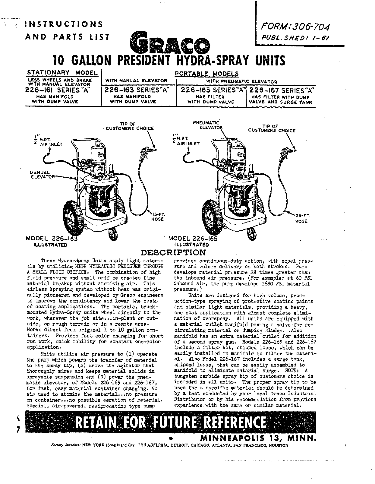
10
GALLON
PRESIDENT
HYDRA-SPRAY
STATIONARY MODEL PORTABLE MODELS
LESS WHEELS AND BRAKE WITH MANUAL ELEVATOR
WlTN MANUAL ELEVATOR
226-161
HAS
WITH
SERIES"A"
MANIFOLD
DUMP VALVE
226-163
HAS MAHIrOLD
WITH DUMP VALVE
CUSTOMERS CHOLCE
TIP
OF
SERIES'A"
226-165
WlTN DUMP VALVE
WITH PHCUMATIC ELEVPITOR
SERIES"6'
HAS FILTER
PNEUMATIC
ELEVATOR
\
UNITS
226-167
HAS FILTER WITH
VALVE AND SURGE TANK
TIP
CUSTOMERS
SERIES"A"
DUMP
OF
CHOICE
ILLUSTRATED
DESCRIPTION
These Hdi-a-Sorav Units aoulv lieht materi-
+Is
by
A
fluid pressure
material breakup without
airless Spraying system without heat
nally pioneered and developed by Graco ensbeers
to
of
mounted HydraSpray units wheel directly to the
work, viterever the job
side,
Works
tainers. Rovides
run
application.
the pump wllich powers the transfer of material
to the spray
thoroughly mixes and keeps material solids
sgayable suspension and
matic elevator,
for
air
on
Special, air-powered, reciprocatinp type
utili& HkH-HYDilAULIC'
SMALL
FLUID
CEIFICE.
and
improve the consistency and lower the costs
coating applications. The portable, truck-
The cmbination
small
orifice creates fine-
atomizing
site
on roqh terrain
direct from original
work,
quick mobility for constant one-color
Units utuize
tip,
or
fast
color changing
air
pressure to
(2)
drive the agitator
(3)
of
fast,
easy material container changing.
used to atomise the material...no pressure
container...no possible aeration
Xodels 226-165 and 2.26-167,
...in-
in
a
remote area.
1
to
pomr
&SS&
air.
was
plant
10
gallon con-
(1)
the pneu-
of
TwtOuGH
of
hich
This
origi-
or
out-
for
short
operate
that
in
No
material.
pump
ILLUSTRATED
provides continuous-duty action,
sure and volume deliver7
develops material pressure
the
inbound
inbound air, the pump develops 1680
pressure.)
Units are desiged
uction-type spraying of protective coating paints
similar
and
one coat application with almost complete elimi-
nation
a
material outlet
circulating
manifold
of
a
second
include
eaSuy installed in manifold to filter
al.
Also
shipped loose, that can be easily assembled to
manifold to eliminate material surge.
tungsten carbide spray tip of customers choice
included
used for
by a test conducted by your local Graco Industrial
Distributor
experience with the
air
pressure.
light naterials, providins a heavy,
of
overspray.
manifold
material
has
an extra
spray
a
filter
Model
in
a
specific material should
qm.
kit,
226-167
all
units. The proper spray tip
or
by
his
on
(For
for
All
units
or
dumping sludge.
material outlet
Models 226-165 and 226-167
shipped loose, which can be
includes a surge tank,
recommendation from previous
same
or
.4th
both strokes. amp
28
times greater than
example:
hiqh volume,~prod-
havins a valve,for re-
similar
equal ?res-
at
PSI
material
are equipped
.Also
for
addition
the
NOTE:
be
determined
material.
60
PS:
with
materi-
A
is
to
be
..
Page 2
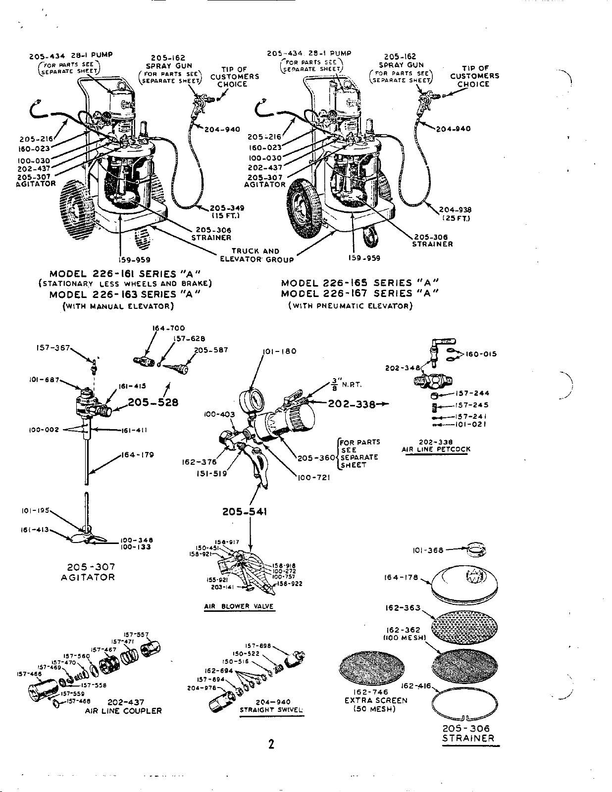
MODEL 226-161 SERIES
(STATIONARY LESS WHEELS AND BRAKE)
MODEL
(WITH
226-
MANUAL
163
SERIES
ELEVATOR)
"A"
"A"
164-700
MODEL 226-165 SERIES
MOOEL 226-167 SERIES
(WITH
PNEUMATIC
ELEVATOR)
"A"
"A"
157-367
AGITATOR
205
-301
157557
AIR
BLOWER VALVE
101-160
,a
./a
3''N.RT.
202-338'
202-3
-157-245
-157-241
nc101-021
202-338
blR LINE PETCOCK
I
AIR LINE COUPLER
.
204-978
204-940
STRbIGHT
SWIVEL
2
162-746
205-306
STRAINER
Page 3
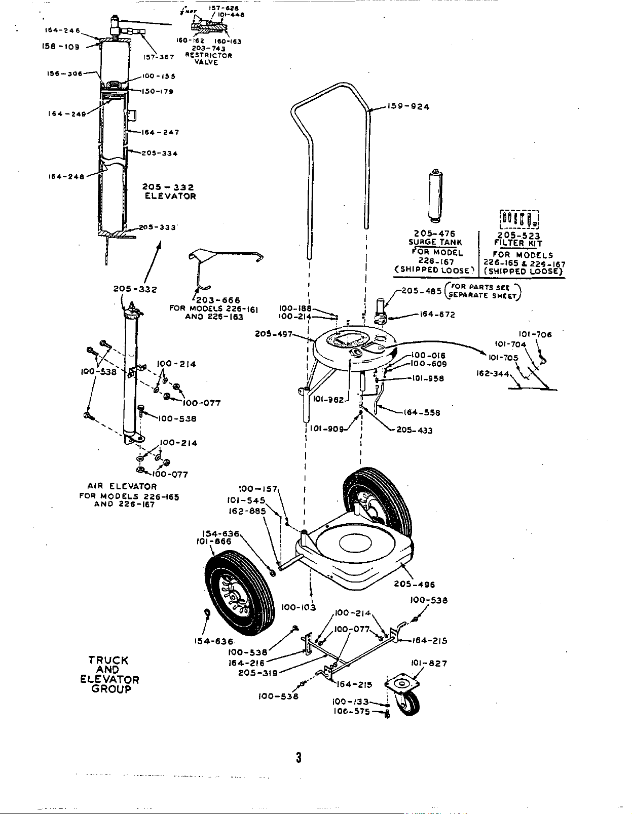
205-332
I
I
I
I
I
I
205-476
SURGE
<SHIPPED
TANK
FORMODEL
226-167
LOOSE\
TRUCK
AND
ELEVATOR
GROUP
3
Page 4

This
PTFE
PTFE
PTFE
PTFE
PTFE
PTFE
tured to exacting
ranted against defective
manship
Excessive
corrosive
not be construed
within the limitations of
equipment
as
set
wear
materials
has
GRACO
forth
in
due to passage of abrasive
through
as
indication of defective parts ing pressures and operating speeds.
IMPORTANT
. ..
been carefully manufacstandards.
materials
the
GRACO
It
is
and/or uork- from
WW-
WARRANTT.
or
this
equipment
this
warranty. require actual
shall
NOTES
Air
x)
than
100
h-ing
c.f.m.
agitator.
per
AIR
REQUIREMENTS
pressures required to owrate
to
1oo.s.i.
lb. of air Dressure to ODerate
continuous operation,
CAUTION:
Do
not
at
nod
this
air
gun
delivery of approxhatew
plus
3
c.f.m.
for
continuous
PmP
range
use
more
PWP.
m-k-
dt
use
h
of
"
WPPH
CARE.
such
as
Air
hire to effectively ground the
tional
be
air
of
the sane type.
materkl
GRACO
sharp
khking,
supply hose 205-216 Includes
hose
WARRANTI
does not cover abuse conditions compressor should delivery 25% me
crimping
is
expensive.
or
unit.
supply hose
is
required,
HANDLE
crushing.
a
static
If
addi-
it
should
To provide reserve capacity for
than
required
ment which
N&:
since
in
ed to atomize the
for
it
is
Consumtion of compressed
this Hvdra-Sorap process air
PREPARATION FOR OPERATION
1.
the hire-braided hpont " lined
hose 205-349 (15')
164-672 protruding
205-485. Connect the end, without swivel 2QL-9LO 162-376 as shorn
attached, to nipple 164-672. See
connect swivel 204-940, attached to other end
this hose, to spray
THREAD
Remove contents arton
or
204-938 (25' ) to nipple separately for removing foreign
from
material outlet manifold entering
gun
at
this
SEM
AT
ANY
WIVF,L
CONNECTION.
Fig.
time.
and
cokzct before reaching unit.
material
1.
DO
DO
NOT
NOT
of
USE
strainer
2OL-999 (accessory) may be purchased
the
205-216--
unit. Attaches to
normal
to
serve.
paint.
in
Fig.
I
e'
NBT
2
operation
NOTE:
2.
A
Graco
matter
air
*THESE
peak
Of
all
air
is
not need-
air
line
from
manifold
ARC
bCCtSSCUIU
load
equip-
is
lm,
air
air
NOTE:
...
it
is
in
2. For operation
purchase these accessories separately...two
high
pressure
a second hose 205-349 (15')
second swivel 2OL-940,
and
a
move nipple 16L-672 and plug from manFfold to raise, apply a little grease to exterior
M5-485, and qonnect valves and hoses
in
Fig.
3. Attaah one end
205-216
end
Of
162-376.' Refer to Fig.
threaded
(drain
Snch location
Check
dump
should be closed. When closed,
a
horizontil position. Refer to
valve of
of
material
second spray tip of
..
2.
to
smce of air Supply and screw other attached to end of air hose 160-023,
hose
into
shutoff valves 205-583.
a
second spray
of
air manifold swivel adapter fitting
1.
NET.
Install a
or
bleed typelin the air supply
that
air
can be turned
manifold
a
second sprav
or
2OL-938 (25'),
customers
15
foot air supply hose elevator, disconnect
205-485
its
knob
Fig.
1.
mn
(2)
~. .
.~
ep
choice.
as
a
205-162 merated elevator,
Re-
shorn faces of handle ends.
NOTE:
equipped with
vith foot
to back of truck base and guide rod into notch at
bottom of bracket.
L.
If
hook over handle.
If
Model 226-165
in
Kale hose studs are line fitting
master
air valve
line
on
and off
in
1.
With air admitted to unit, elevator will raise
unit and hold
disconnected.
Models 226-163. 226-165 & 226-167 are
a
brake-to set brakes push
on
rod protruding from bracket attached
Model 226-161
lift
NOTE:
or
air
agitator 205-307 and connect to
157-367.atop
it
there until air hose
or
226-163 with hand-
up
on
elevator hanger and
If
elevator
226-167 with air-operated
line coupler 202-417,
elevator as shown
4
is
from
160621
down
difficult
sur-
ab line
air
in
Fix.
is
Page 5

5.
vided. Wipe clean
material stirred
consistency
terial
thoroughly making sure there
concentration
container. The pigments must be well dispersed
prevent them from clogging the
strainer
ed into the container of material.
gallon can. the material intake strainer
removed
the agitator propellor into the container.
relation
fluid intake strainer. When
are held
the feet
port the perforated
Fig.
Remove from base the
its
and
or
place a smaller container
inside the
205-306
NOTE:
in
order to
6.
Check
to
in
of
10
or
cake formed
when
Fa
a
small
get
the
position
the perforated plate 162-363
position by the retaining ring 162-Ll6,
foot valve body
plats
3.
PUMP
FOOT
interior
thinned
gallon pail. Stir material
the
10
qallon pail pro-
and
pour
to
the proper spray
is
no
heavy pigcent
on
the bottom
fluid
pump
container, such
the
lower
of
the
must
162-361 as show
intake
is
initially lower-
pump housing and
Poot valve feet
plate and screen
contact and
<ntO
of
of
as
a one
must
of
ma-
pump
SUp-
in
it
the
be
in
should
fice openings.
manual elevator, unhook hanger to lower.
with
air hose 160-023
Refer to Fig.
to
bv air,
necessary, loosen lock
valve 203-743 and turn reetrictor screw'cloclcwise
to decrease
screw
completed. Airrestrictor valve 203-743
ed atop elevator tube. Refer to
a filter kit
refer to illustrated
Form 306-696
205485
ing hose into a waste container. Start pump
opening
ting regulator 205-360 at
Allow pump to operate until all traces
inhibiting
removed. Stop pump and discard.materia1 pumped.
be
used
with
spray
tips
havin$
7.
Lower pump into
Dneumatic elevator, loner by disconnecting
from
material.
elevator air line fitting.
larger
If
1.
NOTE:
8.
9.
The speed at which
is
set
at
factory.
nut
or
in
to a filter
ON-OFT
pg~e~c~o&+.~e to
place with lock
If
unit includes a filter kit
205-523
.~
for
easy conversion
Insert delivery end
pump
nut
and a surqe tank 205-476,
inrt.ruetions
or
a
filter-surp
air petcock 202-338 and set-
30
oil,
with which pump
unit
If
of
is
adjustment
air
restrictor
&rcase.
when adjustment
1.
Fig.
in
senarate
-~
~.
of
manifold
chkaher.
of
material dispens-
p.s.i.
was
Refer
treated,
ori-
unit
with
elevated,
is
Lock
is
is
locat-
205-521
'~~
-
~"
by
Fie
of
rust
is
or
1.
FIG.3
NCrPE:
strainer 205-306 can be removed and reulaced
the extra, more coarse
plied. Refer to Fig.
If
desired, the
-
100
mesh screen
50
mesh screen i62-746 sup-
3.
This
50
mesh
screen
in
with
OPERATION
IMPORTANT
1.
For most satisfactory operating conditions, locate pump and
not
be
sub,iected to temperatures below 65" F.
2.
taininq
particles. Coarse gsind, coagulated, contaminat-
ed and skinned
through
being used, without clogging, can not
factorily sprayed.
OrVice diameter
terial
important that particle's which could plug this
orifice are not present
Sprayed.
and clean filter,
relieved, remove
strainer
light
Fig.
Do no.t attemut to surav materials con-
heaw fillers.
dirt
materials
the openings
in
Due
in
must
be forced under pressure,
3.
Dailp,
4.
&l~,
20L-959
oil
to screen cavity
spray tip through which
before starting to spray, remove
if
used,
wit> air pressure
and
clean screen
(accessol-g),
4.
NOTES
material
that
size
to
in
so
or
other coame
vill
of screen
the extremely
the
material to
of
spray
if
used.
in
strainer nut. See
that thev
not pass freely
or
filters
be
satis-
small
ma-
it
is
very
be
gun.
shut
off
air
and
line
Add
in
NOTE:
unit
for
valves 205-583 and
waste container before starting pump. Refer to
Fin.
2.
.-
10.
end
of
,
inlet
rrill
5..
cates necessary,
"P
VAL'?
move and clean filter cartridge
used. Refer
6.
material
check to be
with feet
7.
screen, tips,
be sprayed
solvent of a twe rec&mended
material beme snrayed. Use of the
may
cause
ents which-could-cause clogging
filter and spray
CLEA"JER.
If
accessories have been added to
two
gun
operation, open material shutoff
insert
Connect swivel 204-940, attached to free
material dispensins hose;
Dailv
or
more often
WITH
OmN
TO
RELEEVE
ends
if
PLMP
DEACTIVATED
MATERIAL
of
to
emerience
or
to
Fig.
1.
w,
intake strainer 205-306. men replacing,
When
remove and clean screen
sure
of
jellinn
that plate 162-363
pump foot
thinning materia1;cleaning filters,
etc.; changing types of material to
or
flushing unit; be sure to
valve.
or
separation of
pn
tip.
Refer to Fig. 3.
bv
manufacturer
of
W
NOT
5
both hoses into
spray
gun
Ldi-
AND
PRESSRE,
screen,
is
wrong
material
strainer,
USE
FILTER
if
in
pump
in
contact
we
CLEAW
solvent
compo-
COMMCN
re-
Of
CLW
Page 6

Nm:
0-nd a specific type
atability
he material by dropping a single drop
1
into a
laterial drop clouds
.ent
is
'orm
a ball, the solvent
.efinitely should not be used.
Thorouah agitation of material should be
lccomolished prior to
E.
1.
;ator
lefer to Fig.
nore turns to the left to
notor. Refer to Fig.
nay be adjusted to
,P
material used.
speed may cause vibration and foaming
he moderate agitation speeds
This
light
progress
is
extremely important that
suspension and held there dbring the entire spray
operation.
5.
hile unit
1.
.fter material has been circulated sufficiently
nd before attempting to spray. When closed,
nob
of
If
manufacturer
of
the solvent to.be used
small
container
or
compatible.
If
AGITATION
Agitation can best be obtained
Snap
air
line coupler
air
2.
fitting
Wn
and agitator
1.
agitator
suit
N.WTE:
3.
Open
manifold dump valve and
permits pump circulate the material under
of
material does not re-
of
solvent, check the com-
of
".he solvent.
disperses readily, the
drop tends to string
is
not compatible
OF
MATERIAL
~umpinn
air
1.
material to soray
valve
start
Speed
the particular viscosity
Excessive agitation
at
for
as
202437
WFU
be
x)5-528,
agitator
of
agitation
all
thinning
of
the
If
and
follows:
onto agi-
energized.
t'm
air
of
material.
times.
start
or
pump.
load.
1.
Lift
hinped inspection plate and examine
of
agitaiion through hie
all
Allow
agitator to continua operation
is
supplying
material
SUPPLYING MATERtAL
Stop pump and close manifold dump valve
dump valve
is
in
a
horizontal position.
in
cover.
solids are
to spray
TO
GUN
DUt
gun.
materi-
the
sol-
or
It
in
inbound air pressure.
100
0.s.i.
5.
hold spray
surface to be sprayed, with
U
spray
Hydra-Spray technique
ventional spraying with air, except
greater distance spray tip should be held
work surface, the
duced which results
and the positive action used when triggering gun.
in this Instruction Sheet
cating troubles which may occur during spraying.
Also
spec'ific information pertaining to the spray
pump, regulator and manifold
While spraying be sure at
gun
perpendicular (approx.
inches
from
will
NOTE:
refer to separate Instruction Sheets
surface
cover satisfactorilg. NOTE: Good
Refer to the
Do
not
set
hieher than
all
its
greater
similar
spray tip
if
or
is
very
for
larger
coatinq thichss pro-
in
less pattern overlapping
SERVTCE
for
DIAGNOSIS
assistance
or
filter.
times to
90")
12
the
material
to
con-
the
from
in
for
to
to
CHART
10-
gun,
SAFETY PRECAUTIONS
The Hydra-Spray equipment develops extremely
high
material
until relieved by shutting off the
and releasing the material pressure by opening
manifold dump valve.
high pressure stream
spray
gun
with the hand
penetrate the
HANDLE
YOU
WULU
lowing safety precautions should be observed:
a
Nevar
the spray tip. (Use
is
recommended.)
Never place
in contact with
pressure which
is
allowed to come
or
any
skin
and cause physical harm.
THE
HYDFA-SPRAY
ANYGUN:
point
put the hand
gun
the
any
LO-
part
remains
In
operation,
of
material released from
in
part
of
human body
GUN
OR
UNLOADED.
directly at the face.
or
fingers directly over
of
protective leather gloves
tip
or
gun
of
the body.
in
the system
air
to pump
if
the fine
direct contact
it
AS
CAUTIOUSLY
The
nozzle directly
could
AS
fol-
2.
@en
accessory),
.alve body when open. Refer
3.
92-38.
:losed
-
.he
mmp
iqueezing trigger
itarts
ressure, from
and
air
is
pump operating, forcing material, under
4.
;o
obtain desired breakup and spray pattern
naterial.
naterial,orFfice diameter and fan angle
;ip.
TO
justing knob
:o
iecrgaze pressure turn
JOTE:
1ump
'orced through the orifice
levelops material pressure
The amount
determines
material
if
used. Handles are parallel to
open ON-OFF
With petcock open, mifold dumu valve
air
pressure admitted, the pumping action of
controlled by operation
regulator
gun
Adjust pump to pressure required
This
setting
increase air pressure to pump, turn
of
regulator
the
shutoff valves
pump
air
205-360
of
spray
spray tip.
will
205-360
it
of
air
pressure supplied to the
pressure
205-583
to
Fig.
2.
control petcock
set to control
of
spray
gun
open automatically
vary due to viscosity
clocMse and
gagniegc&o+&e.
of
the material
in
spray tip. Pmp
28
times that
gun.
of
of
of
spray
ad-
the
-
lieve material pressure
ing
to
gun
for
a
a
fully
prevent leaks
as pressurized stream
tip.
Always
the material'to spray
to prevent sparking. The high velocity
material through the spray tip may cause static
electricity to be developed. Use
braid
material dispensing hoses
tected hose.
proper grounding out
shut
off
air pressure to pump and re-
in
remove
and
gun
tip
service.
remove tip from
tighten threaded connections care-
securely, and handle hose carefully to
that
could cause physical harm same
be sure that the equipment supplying
Also
be
of
system before attempt-
or
screen and/or removing
gun
to clean
COD~Q
gun
sure
fiom
orifice
is
properly grounded
only
or
to provide
the compressor.
static pro-
for
flow
metal
6
..
it.
in
the
gun
of
Page 7

PREVENTIVE MAINTENANCE
At
least twice daily and durine any lenethy:
of
interruption
relieved: remove and clean
filter
manufacturer
parts
nozzle
~.
dry
in
~ ~ ~~
in
sprayinq,
clean
solvent
of the material beine smayed. Blow
with
air
clean
pressure.
solvent during shut
with
material
gun
spray tip and tip
of
a
type recommended by
_.
Also
kerse
down
pressure
.
gun
periods.
SHUTDOWN PROCEDURE
To
maintain
this
shutdown procedure
day's spraying must be diligently followed:
each
1.
ON-OFF
Handle
closed.
and spray
This
to
terial has stopped draining, remwe and clean
Shut off air to pump
air
is
at right angle to petcock body when
2.
Relieve material pressure in
gun
will
drain
allow
back into material container.
efficient operation of unit,
at the completion
by
control petcock
by
opening
the material trapped in the system
drump
closing pump
202-338.
valve of -ifold.
See Fig.
pump,
of
After
filter cartridge
valve.
3.
Remove spray tip and filter,
i'rom
spray
type solvent and
bristled brush.
205-541
air through tip
open end
spray
cotmuended
spraying again.
em
from dispensine hose unless the unit
completely flushed. Keeping
with material
1.
flushing
gun.
attached to air manifold
of
forward end submerged
gun
type
..
unit.
m:
hose , final flushing with solvent
of
all external moving pump
rusting
unit
ma-
follow
paragraph entitled
of
or
screen,
Immerse
wash
Using the air blower valve
from
filter.
solvent
NOTE:
will
Water based paints
the wetted parts. To completely flush
the procedure outlined
in
thoroughly with a fine
front to back and through
Refer to Fig.
until ready
Do
not remove the swaq
minimize~the
FLUSHINC
if
used. Close
clean
recornended
162-376,
1.
in
&&
to
unit
fully
necessity for
will
DAILY
and also
parts
to prevent the
in
UNIT.
drain
if
used,
blov
Keep
re-
start
is
to be
charged
requke a
Oiling
subsequent
-SERVICE
TROUBLESOME
Fump
fails
Pump operates, but insufficient material discharge.......
Excessive surge
Insufficient material breakup..
Tails
Spray
Too
heavy a coating thic.ess
CHECK
to operate,
at
in
spray pattern............
gun
spitting.............
POINT
NO.
l........
2
........
3........
L........
5........
6
........
7........
e........
9........
lo........
ll........
12........
l?........
U......,.
no
material
spray
.............................
gun
............................
mssmm
Restricted
Insufficient air capacity.
Air
valve closed
Air
regulator inoperative
Air
regllator set too high.
Material too viscous
Insufficient
Clogged materid intake strainer.
Clogged material filter, tip
Hish flow rate-tip orifice too large.
Improper
Surge chamber inactive,
Worn,
Worn
ak.
material
or
worn
damaged
or
obstructed pump valves
DIAGNOSIS
sIMPpOM.5
discharge.
..........................
.......................
..........................
CAUSES
supply line.
or
clogged.
in
spray
gun
or
obstructed
if
.............
or
set too
container.
or
tip filter.
tip.
used.
gun
parts.
or
packings.
low.
CHECK
POINT
1-3-4-6-6-9
2-4-7-Y,
1-2-9-10-12
1-2-3-4-6-9-11
1-24-6-ll
13
5-10-11
NOS.
-
MAINTENANCE
IMPORTANT NOTES
1.
solvent. and material
particles rbich could clog strainer screens andl
or
and smav
clean
ready to
when not in use, shut
Keev unit, mixine container. thinner,
plug the small orifice
2.
Keep lower
head immersed
mn
solvent after
start
sprayine again.
-3.
TO
reliive-unit
CLEAV
and free
in
spray tip.
vump
Assembl-f filled nith
in
flushin4
off
recommended type
unit and until
Of
unnecessary pressure
air pressure to pump
of
foreisn
and relieve material pressure
dump valve
dicates necessar , drain filter
more
~
and close dump valve.
4.
Daily
filter
of
manifold
or
cart:idne
more often
7
..
....................
or
or
in
filter.
if
screen.
system by opening
experience
or
surge tank, re-
if
used, and
in-
Page 8

5.
If
out
filter
as often as experience indicates necessary. Stop
pump and open dump valve. After material has
drained completely
6.
cressure
156-967
llsed). Daily,
edd
light oil to screen cavity
fer to Fig.
suree tank
Darts
Shut off air pressure to unit and relieve
in
air line, before removins screen 9. Eecirculate solvent
in
air
line
clean
L.
205-L76
installed,
from
tank, close dump valve.
strainer 20k-999 (accessory
this screen and at reassembly
is
beine used with- trigger of spray
it
should be drained
in
nut 156-944. Re-
if
FLUSHING UNIT
The frequency vith which unit should be flush-
ed deoends upon
generil operating conditions, and usage of unit.
It
is
wi5e to establish a re&= flushing scheU-
In
ule.
flush unit dailv while
~~ ~~ ~~~~~
flushing may prbve satisfactory. unit
flushed
17
commended for use with the material,
if
ed
.type
connect ak'hose to agitator and connect
elevator to raise unit
hook hanger over truck ha.ndle. manifold
spray
operatink by squeezing trigger of spray
rrill
system
flushed Out as much Daterial as possible, Stop
and open manifold dump valve.
a1
stopped draining, close manifold dump valve.
position
mately
into pail of solvent.
direct
to
pressure through the system, flushing the internal
cavities of manifold and filter
solvent appears at
in
clean
separate Instruction Sheet for the spray
spray
to hose again.
solvent and
202-338.
through system and back into pail
10
lower immersion pump.
aP.d connect material hose to spray
some instances
at
flush
unit with thinner
1.
Remove Spray tip and
used,
from
solvent.
2.
With
3.
With
gun
pump air, forcing the material out
back into container. When the
from
all
L.
Remove container
in
2
gallons'
5.
Set air to pump at approxhately
gun
start
pump.
system and remove spray
6.
Remove spray
in
accordance with procedure outlined in
gun
7.
Direct end
to
15
minutes. Wash
8.
After thoroughly flushing unit stop pump
type
or
types
of
material pumped, chamber, close
it
may be desirable to
in
other cases less freouent
must2
the end of each wurkine
or
spray
Sun
and
soak
air
SUPPlY
PmP
into
material container and
loops
in
to
unit
or
manually
air petcock
hose. After material has
of
its
dace a pail containine. approxi-
of
comGtible solvent: Loxer pump
to material container and trigger
Runp
will
move the solvent, under
gun,
stop
ppn.
gun
from
head immersed
start
Allow
thinner
in
solvent until attached
of
material hose into pail of
pump by opening air line petcock
or
solvent to circulate
material
week.
solvent
glm
202-338
Drain
material from base and
pump,
hose and thorou5hly
of
as
follows:
filter cartridge, using thinner oi'solvent may be necessary.
in
clean recommend-
turned
or
for
from
On,
raise and
open, direct Tvith a removable
start
air
excess materi-
surge tank. When
release pressure
a period
exterior of
gun.
Thorough-
type re-
dis-
it
to
pump
gun.
Unit
of
the
has Agitator air motor 101-687
Pump
20
p.s.i.,
gun
gun.
Keep
of
Squeeze overflowing with kerosene.
'gun
start
pump.
fill
hose and spray qn with solvent.
filled with solvent OVerniQht
readv to soray aeain.
,
Pior to char&% anit with material.
10.
operating, by squeezing trigger of spray
and continue ooeratinn until most
been blown
from loops
if
used. After draining tank of
11.
lower pump into container, connect
agitator and charge unit with properly mixed
material.
NOTE:
tmes of material, flush
EVER,
a
be required-and
-
Also
if
to be sprayed recommends usins
thinner
the
first
the possibility of separation
terial components. The sur3e tank
thoroughly scrubbed clean. Surge
Allow
Close Spray
out
in
hose and fnter
Replace container of material upon base,
When chansins colors
lonaer circulation oeriod
manufacturer of another
or
solvent, the thinner
flushing
or
filter should be removed and par.ts
and open air
pump
to operate long enough
gun
and raise pump. Start
of
sysiem.
its
dump valve.
Drain excess solvent
unit
in
some casks a second flushing
must
be flushed out to eliminate
plur:
to
facilitate
line
or
breekend until
for
about 5 minutes
of
solvent has
or
surge chamber.
filier
air
or
incompatible
as described,
will
type
of
a
different trpe
or
solvent used
or
jelling of
or
tank
cleaning.
AGITATOR
must
be properly
ofled with a light
is
shutdorm
Of
8
hours
some moisture and
lubricated before shutdown,
oil
motor:
1.
2.
3.
Air
than to be oiled. However,
has been used
have been followed
imwhich case
follows:
1.
or
or
Remove oiler screw from air motor top.
Apply 3 to
Replace oiler screw and run motor
about
motor should require
161-41
Remove exhaust muffler
air
motor
oil,
whenever
is
not to
more.
if
1/2
minute.
or
other improper oiling practices
air
motor should be flushed
be operated
All
compressed air oontains
air
motor
is
not
rust
may
L
droos
of oil to oiler.
no
attention other
if
too heavy an oil
guming
FIG.
of rotor
OILER
5
for
~ ~ .~
may
SCREW
161-415.
~~~l~~~
muffler.
a
petcock to
to
~~~p
unit
gun
~ ~~ ~~
or
sur&
hose to
HOW-
necessarilv
-
material
of
in
ma-
tank of
is
equipped
a
period
nrouerlv
.-~~
result." To
for
result,
as
Fill to
.,
Page 9

'
PTFEPTFEPTFE
2.
Remove
5.
3.
Fill
dllow a
,
>.
Pig.
.
then start ab motor.
smooth operation has been achieved
been
blown
screw and
NOTE:
MUl'a.
If
oiler from
oiler
with
soaking
from
a*haUSt. stop
fFu
oiler with a light
MAgE
NO
ATPMPT
air
motor top cap. See
kerosene. Replace oiler.
period of, 5 to
Run
motor
slowly.
and
LUOtOr,
M
DISASSMBLB
kerosene
remove ouer
air
motor
it should need repab, contact
10
minutes,
After
oil.
ADl
pour
nearest Graco Authorized %mice Depot.
FLUID SHUTOFF VALVE
205-583
Worn
"0"
rings,
valve to fail to operate.
air
shut off
supply, relieve
(ACCESSORY\
ball
seat
If
or
ball
sesvice
fluid
pressure
may
cause
is
necessary,
and
move valve. Place valve body in a vise and drive
in
valve
the two pina out of holes
from
valve cap
body
being
careful not to
body.
as this would shear off the locating pins in
body.
worn
"On
moving
handle shaft down
See
Fig.
6.
or
damaged parts. NOTE:
ring
15L,-7lJ
ball
162-831.
Disassemble and replace
can be best removed
from
intb
body
cavity in valve
With
and then pushing
Runwe
turn cap
valve
any
handle removed,
by
first re-
body'.
has
LUERICATION
pressure,
re-
inner carity of cup leather
oil.
exposed surface of elevator guide tube
See parts illustration for location of parts.
structions and parts identification.
..
fIG.6
ELEVATOR
2
Every
to 6 weeks
unscrew
Replace cap. Raise elevator
PUMP. REGULATOR,
FILTER OR SURGE CHAMBER
Refer to separate sheet
with
and
remove cap
elevator free
&-ab.
150-179
SPRAY
for
maintenance
of
Fill
vith
SdE
and
lubricate
1&-7A7.
GUN AND
air
20
in-
REPAIRING HYDRA-SPRAY HOSE
dra-Spray hose
" inner
wire braid
lining
Outer
and should be handled with care.
becane damaged it can be salvaged
Couplings to
the
Graco detachable
Of two parts. the female Mvel stud
the sleeve
162-366.
in the following
NUTE:
F-20898
A hose coupling fixture Graco
specifically designed to facilitate the
assembly of couplbgs upon this tppe of hose
be obtained
from
of a thu piece assembly block and
as
shown
tool
1.
hose
With
be cut
and
in
Position the two piece assembly block on.
plain side of block
clamp
Cut off With a fine tooth hand
is
constructed of tiupont
tube with stainless steal
CWer. This hose
broken
and
ends
reusable couplings consist
is
exoensive
If
hose should
by
of
assembling
hose sections.
201.-937
and
and are assembled upon hose
manner:
No.
factory. This fixture consists
may
an
assembly
Fig.
7,
8
and
.
in
a dse
9.
toward hose end to holding block
as
shown
in
Fig.
7.
hack saw.
3. Add a drop of oil to the end
vires, position assembly.block
vith
of
Its
the
groovad
side toward end of hose just cut and slide block
onto hose until
an
of
. . ~
,jvW
inch beyond the end of hose. See
ASSEMW
no.
4.
ap the threaded e.nd
ass&ly twl
or
rmrunc
F-20198
protrudes about
moL
as
shown
in
in
place
on
hose, insert end of tool
1/32
to
Fig.
CIUIION-
DO
NOT
CRUSH
HO5L
of
sleeve 162-366
Fig. 8 and while
it
into hose and end of sleeve into groove.
1/16
8.
2.
about
2
inches
not crush the hose-apply
Remove hose
from
from
block
end just cut.
only
and
grip
In
CAUTION:
vise
00
enough pressure
on the viae jaws to hold while forcing the sleeve
onto hose.
9
5.
While twisting sleeve
vith a wrench apply
as
td and
sleeve
body
is
forced onto hose
block to slide back. After about & inch
hose
is
covered, remove the block and continue
back
and
pressure to
forth
assembly
allow
Of
to force sleeve onto the hose until end of hose
reaches the
Fig.
10.
shoulder
in
sleeve. Refer to
 Loading...