

Page 1

Instructions
Parts
PLURAL COMPONENT
Mixer Manifold
3000 psi (21.0 MPa, 210 bar) Maximum Working Pressure
Model 215625 Series C
Low Volume Mixer: 1/4 npt fluid outlet; for use in low
volume applications, such as air spray urethanes.
Model 215626 Series C
High Volume Mixer: 1/2 npt fluid outlet; for use in high
volume applications, such as airless spray or high solids
epoxy.
Model 241692 Series A
Includes Model 215626 and a static pipe mixer.
Ball Valve Kit 218413
Updates the handle and ball valve of Series A,
Model 215625, Low Volume Mixer. See page 10.
Ball Valve Kit 218414
Updates the handle and ball valve of Series A,
Model 215626, High Volume Mixer. See page 10.
307400P
Read warnings and instructions.
See page 2 for Table of Contents.
GRACO INC.ąP.O. BOX 1441ąMINNEAPOLIS, MNą55440-1441
Copyright 1980, Graco Inc. is registered to I.S. EN ISO 9001
06305
Page 2

Table of Contents
Warnings 2. . . . . . . . . . . . . . . . . . . . . . . . . . . . . . . . . . . . . .
Installation 5. . . . . . . . . . . . . . . . . . . . . . . . . . . . . . . . . . . . .
Operation 6. . . . . . . . . . . . . . . . . . . . . . . . . . . . . . . . . . . . .
Troubleshooting 8. . . . . . . . . . . . . . . . . . . . . . . . . . . . . . . .
Service 9. . . . . . . . . . . . . . . . . . . . . . . . . . . . . . . . . . . . . . .
Symbols
Warning Symbol
WARNING
This symbol alerts you to the possibility of serious
injury or death if you do not follow the instructions.
WARNING
EQUIPMENT MISUSE HAZARD
Equipment misuse can cause the equipment to rupture or malfunction and result in serious injury.
Parts 10. . . . . . . . . . . . . . . . . . . . . . . . . . . . . . . . . . . . . . . .
Technical Data 13. . . . . . . . . . . . . . . . . . . . . . . . . . . . . . . .
Dimensions 14. . . . . . . . . . . . . . . . . . . . . . . . . . . . . . . . . . .
Graco Warranty 16. . . . . . . . . . . . . . . . . . . . . . . . . . . . . . .
Graco Information 16. . . . . . . . . . . . . . . . . . . . . . . . . . . . .
Caution Symbol
CAUTION
This symbol alerts you to the possibility of damage to
or destruction of equipment if you do not follow the
instructions.
D This equipment is for professional use only.
D Read all instruction manuals, tags, and labels before operating the equipment.
D Use the equipment only for its intended purpose. If you are not sure, call your Graco distributor.
D Do not alter or modify this equipment.
D Check equipment daily. Repair or replace worn or damaged parts immediately.
D Do not exceed the maximum working pressure of the lowest rated system component. Refer to the
Technical Data on page 13 for the maximum working pressure of this equipment.
D Use fluids and solvents which are compatible with the equipment wetted parts. Refer to the Tech-
nical Data section of all equipment manuals. Read the fluid and solvent manufacturer’s warnings.
D Handle hoses carefully. Do not pull on hoses to move equipment.
D Route hoses away from traffic areas, sharp edges, moving parts, and hot surfaces. Do not expose
Graco hoses to temperatures above 66_C (150_F) or below –40_C (–40_F).
D Wear hearing protection when operating this equipment.
D Do not move or lift pressurized equipment.
D Comply with all applicable local, state, and national fire, electrical, and safety regulations.
2 307400
Page 3
WARNING
INJECTION HAZARD
Spray from the gun, leaks or ruptured components can inject fluid into your body and cause extremely
serious injury, including the need for amputation. Fluid splashed in the eyes or on the skin can also
cause serious injury.
D Fluid injected into the skin is a serious injury. The injury may look like just a cut, but it is a serious
injury. Get immediate medical attention.
D Do not stop or deflect leaks with your hand, body, glove or rag.
D Always have the tip guard and the trigger guard on the gun when spraying.
D Do not “blow back” fluid; this is not an air spray system.
D Check the gun diffuser operation weekly. Refer to the gun manual.
D Be sure the gun trigger safety operates before spraying.
D Lock the gun trigger safety when you stop spraying.
D Follow the Pressure Relief Procedure on page 8 if the spray tip clogs and before cleaning,
checking or servicing the equipment.
D Tighten all fluid connections before operating the equipment.
D Check the hoses, tubes, and couplings daily. Replace worn or damaged parts immediately. Do not
repair high pressure couplings; you must replace the entire hose.
MOVING PARTS HAZARD
Moving parts can pinch or amputate your fingers.
D Keep clear of all moving parts when starting or operating the pump.
D Before checking or servicing the equipment, follow the Pressure Relief Procedure on page 8 to
prevent the equipment from starting unexpectedly.
3307400
Page 4

WARNING
FIRE AND EXPLOSION HAZARD
Improper grounding, poor ventilation, open flames or sparks can cause a hazardous condition and result in a fire or explosion and serious injury.
D Ground the equipment and the object being sprayed. Follow the grounding instructions on
page 5.
D If there is any static sparking or you feel an electric shock while using this equipment, stop spray-
ing immediately. Do not use the equipment until you identify and correct the problem.
D Provide fresh air ventilation to avoid the buildup of flammable fumes from solvents or the fluid
being sprayed.
D Keep the spray area free of debris, including solvent, rags, and gasoline.
D Before operating this equipment, electrically disconnect all equipment in the spray area.
D Before operating this equipment, extinguish all open flames or pilot lights in the spray area.
D Do not smoke in the spray area.
D Do not turn on or off any light switch in the spray area while spraying or while operating if fumes
are present.
D Do not operate a gasoline engine in the spray area.
TOXIC FLUID HAZARD
Hazardous fluid or toxic fumes can cause serious injury or death if splashed in the eyes or on the skin,
inhaled, or swallowed.
D Know the specific hazards of the fluid you are using.
D Store hazardous fluid in an approved container. Dispose of hazardous fluid according to all local,
state and national guidelines.
D Always wear protective eyewear, gloves, clothing and respirator as recommended by the fluid and
solvent manufacturer.
REACTIVE CHEMICALS HAZARD
Graco Inc. does not manufacture or supply any of the reactive chemical components that are used in
this equipment, and is not responsible for their effects. Because of the vast number of chemicals that
could be used, and their varying chemical reactions, the buyer and user of this equipment should determine all facts relating to the materials used, including any of the potential hazards involved. Particular inquiry and investigation should be made into potential dangers relating to toxic fumes, fires, explosions, reaction times, and exposure of human beings to the individual components or their resultant
mixtures. Graco assumes no responsibility for loss, damage, expense, or claims for bodily injury or
property damage, direct or consequential, arising from use of such chemical components.
4 307400
Page 5

Installation
Grounding
Proper grounding is an essential part of maintaining a
safe system.
To reduce the risk of static sparking, ground the pump.
Check your local electrical code for detailed grounding
instructions for your area and type of equipment. Be
sure to ground all of this equipment:
1. Pump: use a ground wire and clamp as instructed
in your pump instruction manual.
2. Fluid hoses: Use only grounded hoses with a maximum of 500 feet (150 m) combined hose length to
ensure grounding continuity.
3. Spray gun, manifold, or dispensing valve: obtain
grounding through connection to a properly
grounded connection to a properly grounded fluid
hose and sprayer.
6. All solvent pails used when flushing, according to
local code. Use only metal pails, which are conductive. Do not place the pail on a nonconductive
surface, such as paper or cardboard, which
interrupts the grounding continuity.
7. To maintain grounding continuity when flushing or
relieving pressure, always hold a metal part of the
gun firmly to the side of a grounded metal pail,
then trigger the gun.
Installation (See Fig. 1)
For assistance in setting up a plural component system, contact your Graco distributor. This will help assure that you select the proper type and size equipment for your job.
Use the spacer (40), screws (37), nuts (38) and lockwashers (39) provided to mount the manifold.
Connect the supply lines from your pump to the manifold inlets (R & Q).
4. Object being sprayed: according to local code.
5. Supply Containers: according to local code.
R
Connect your static mixer or hose to the material outlet
(S). Model 215626 has a 1/2 npt(m) outlet, and model
215625 has a 1/4 npt(m) outlet. Model 241692
includes a static mixer with a 3/8 npt(m) outlet.
Q
Fig. 1
S
Model 215626 Shown
05764
5307400
Page 6
Operation
Start-up
The mixer manifold was tested in oil, which was left in
to protect the manifold. Before operating, thoroughly
flush the manifold to prevent contamination of the
fluids.
Flushing Procedure
CAUTION
Be sure to label all fluid path parts “component A” or
“component B” when disassembling them. Doing so
prevents interchanging A and B parts during reassembly, which will contaminate the materials and the
fluid path through the equipment.
Color-coded chemically resistant tape may be used
to label the parts. Use blue for component A, green
for component B, white for solvent, and red for mixed
material.
Place the handle in the UP, or closed, position. Turn on
the solvent supply pump. Open one of the solvent
valves. Release the spray gun safety latch. Hold the
gun firmly to the side of a grounded metal pail, then
trigger the gun to flush. Flush until all contaminants
and oil are removed. Release the trigger, engage the
safety latch, and close the solvent valve. Repeat for
the other solvent valve.
Any ratio check valves on the manifold output side
must be flushed. Place a container under both valves
to catch the waste solvent. Flush the valves after triggering the gun, one side at a time.
Solvent may channel through viscous fluids and leave
a coating of mixed fluid on the inner tube of your hose.
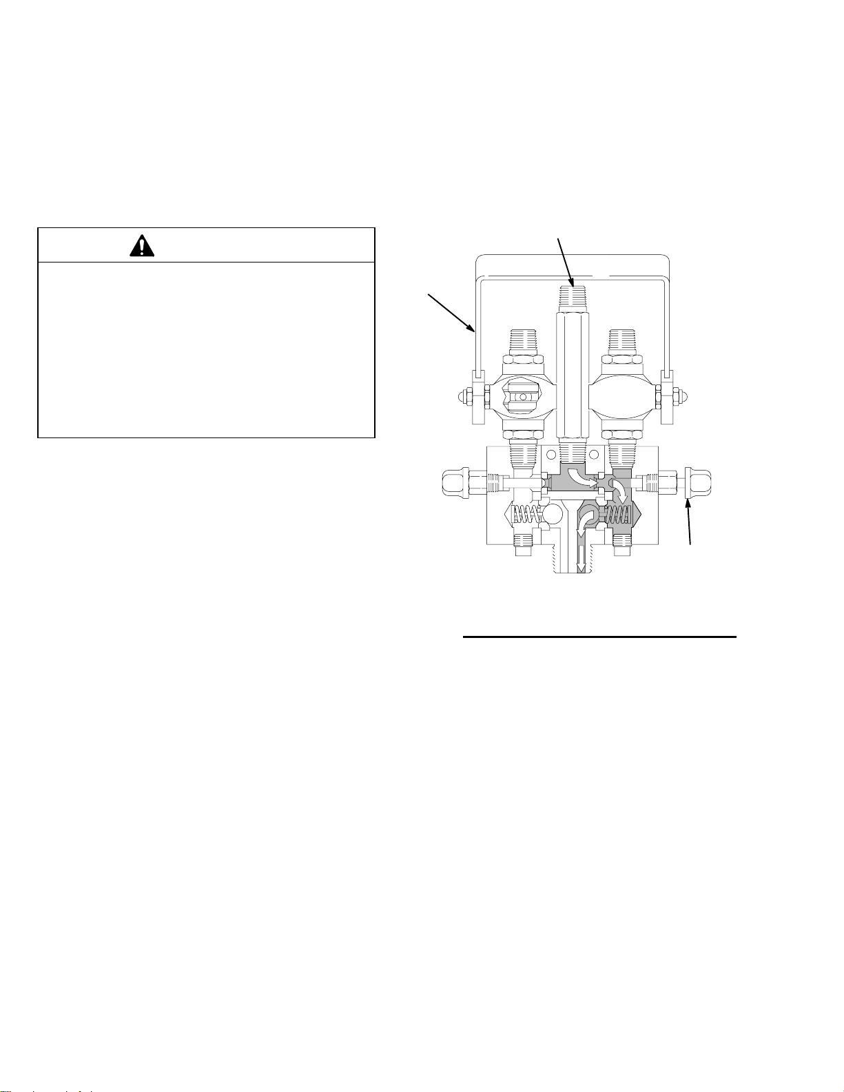
Fig 2 shows the handle in the UP, or closed, position and the
right solvent valve open with solvent flowing through the
right fluid chamber and out through the mixing chamber.
Solvent
Handle
up
Fig. 2
Resin
(A)
Solvent out
Hardener
(B)
Solvent
valve
shown
open
05767
6 307400
Page 7
Operation
e
Be sure all fluid is thoroughly flushed from the hose
after each use.
Disassemble all other dispensing equipment, as necessary, and clean thoroughly.
CAUTION
To prevent fluid from setting up in the dispensing
equipment, flush the system frequently. Be sure
there is adequate solvent in the solvent supply
before starting to spray.
Dispensing
To dispense the resin and hardener, turn on the supply
pumps. Then push the handle forward (DOWN) to the
open position. To stop the flow, move the handle to the
UP or closed position.
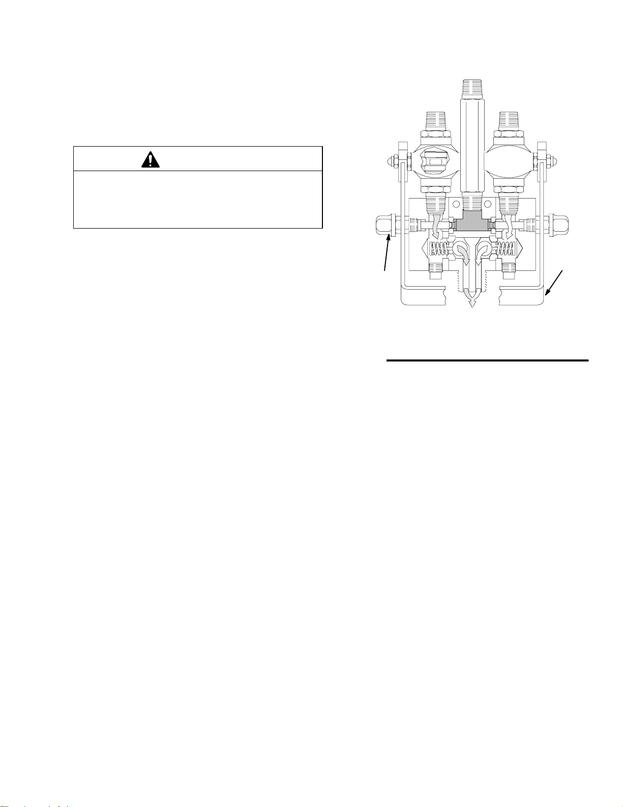
Fig 3 shows the handle in the DOWN, or open, position, solvent valve closed, and resin and hardener flowing through
the manifold.
Solvent
valve
shown
closed
Fig. 3
Resin
(A)
Solvent
Hardener
(B)
Handl
down
05766
7307400
Page 8
Operation
Pressure Relief Procedure
WARNING
INJECTION HAZARD
The system pressure must be manually
relieved to prevent the system from
starting or spraying accidentally. Fluid
under high pressure can be injected through the
skin and cause serious injury. To reduce the risk of
an injury from injection, splashing fluid, or moving
parts, follow the Pressure Relief Procedure
whenever you:
D are instructed to relieve the pressure,
D stop spraying,
D check or service any of the system equipment,
D or install or clean the spray tip.
Troubleshooting
1. Close the mixer fluid valves.
2. Flush the dispensing equipment as described in
the Flushing Procedure on page 6.
3. Shut off the fluid and solvent pumps.
4. Hold a metal part of the spray gun firmly to a
grounded metal pail, and trigger the gun to relieve
pressure.
5. Engage the gun safety latch
6. Open any drain valves, and leave them open until
you are ready to spray again.
7. If fluid has hardened in the hose or mixer, close
the fluid valve, shut off the fluid and solvent
pumps, and slowly loosen the fluid inlet hose(s) to
relieve pressure, then remove the dispensing
hose.
1. Relieve the pressure before you check or service
WARNING
To reduce the risk of serious injury whenever you
are instructed to relieve pressure, always follow the
Pressure Relief Procedure above.
Problem
Little or no resin (A) output
Little or no hardener (B) output The fluid inlet is plugged. Clean the inlet, remove the
The mixed fluid will not flush out There is hardened fluid in the mixing
Cause Solution
The fluid inlet is plugged. Clean the inlet, remove the
The fluid supply container is empty. Refill the fluid supply.
The fluid supply container is empty. Refill the fluid supply.
chamber.
The solvent supply container is
empty.
The solvent is not compatible with the
fluid.
any system equipment.
2. Check all possible causes and solutions in the
Troubleshooting Chart before disassembling the
manifold.
obstruction.
obstruction.
Clean the chamber with a compatible
solvent; service it as necessary.
Refill the solvent supply.
Change to a compatible solvent.
8 307400
Page 9
Service
Manifold Repair (See Page 10. )
WARNING
To reduce the risk of serious injury whenever you
are instructed to relieve pressure, always follow the
Pressure Relief Procedure on page 8.
Note: Repair kits are available for the manifold. Parts
included in the kits are indicated with a †, for example
(9†) See page 11.
1. Relieve the Pressure.
2. Remove the twelve socket-head screws (2) to
separate the two valve housings (8) from the
manifold housing (7). Remove all parts from the
housings.
3. Clean all parts thoroughly in a compatible solvent.
Use a soft bristle brush to clean the manifold
passageways.
4. Install the two check valve assemblies (9†) and
valve seats (6†) in the manifold housing (7).
5. Install the needle valve (12), back-up ring (4**),
and seal (3†) in each of the valve housings (8).
7. Tighten the needle valve slightly, so that the
tapered end centers in the seat (6) and holds its
position.
8. Turn the six socket screws (2) oppositely and
evenly to 60–70 in-lbs (6.7–7.9 NSm). Back off the
needle valve (12) slightly.
9. Repeat step 8 as the torque will relax.
CAUTION
Be sure to tighten the six socket screws (2) evenly.
The upper four screws, which surround the needle
valve assembly (12), are critical in ensuring that the
needle seats properly. If the bottom two screws are
over-tightened, they will throw off the alignment.
10. Repeat the procedure from step 9 on the other
valve housing (8).
Ball Valve Repair (See Page 10.)
Note: Repair Kit 217560 is available for the ball valves.
Parts included in the kit are indicated with an asterisk,
for example (18*). See page 11.
6. Install six socket-head screws (2) through one
valve housing (8) and into the manifold housing
(7), so the distance between the housings is
0.060 in. (1.5 mm).
When reassembling a ball valve (13 or 24), install the
ball (18* or 29*) so that the round hole aligns with the
main passageway of the valve body and the square
hole aligns with the stem (21 or 32) passageway.
9307400
Page 10
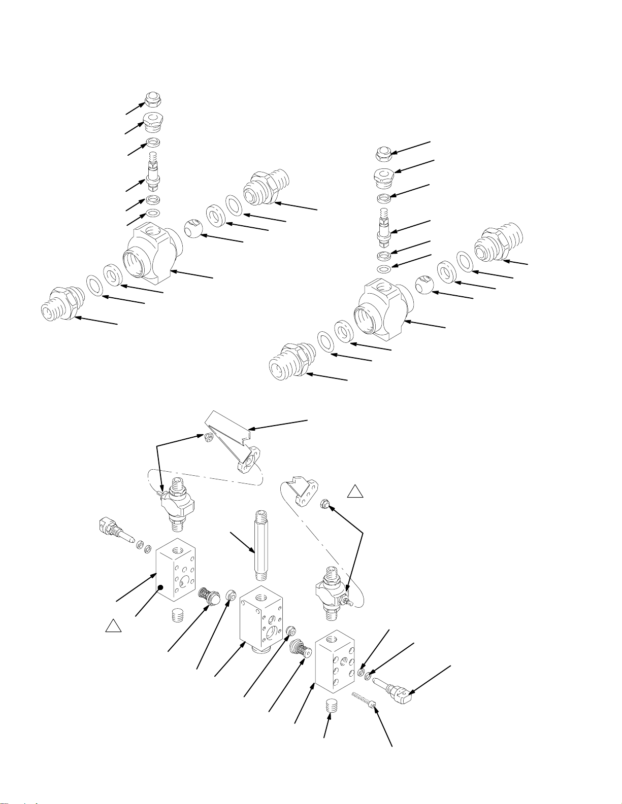
Parts
Ref No.13
Ball Valve 215622, Series B
Low Volume
14
20
*17
21
,
*17
*16
15*
19*
22
Ref No.24
Ball Valve 215623, Series B
High Volume
25
31
28
19*
15*
32‡
22
18*
28
27
23
26
33‡
29
34‡
33‡
05769 05768
26
30
30
13 or 24
8
41
1
9†
6†
11
Model 215625 Manifold, Series C
Model 215626 Manifold, Series C
Instruction label covers parts 7 and 8
1
when assembled.
5
13 or 24
3†
4†
12
7
6†
9†
8
1
Torque twice to 60–70 in-lb.
2
(6.7–7.9 NSm)
05765
10 307400
Page 11

Parts
Models 215625 and 215626, Series C
Ref
No. Part No. Description Qty.
1 100721 PLUG, internal hex; 1/4; 1/4 npt 2
2 104472 CAPSCREW, hex hd;
10–32 x 1–1/2 12
3† 105694 SEAL, shaft; SST and PTFE
4† 177019 RING, back-up; Delrin
5 177021 NIPPLE, pipe, hex; 1/4 npt 1
6† 177022 SEAT, valve; Delrin
R
7 HOUSING, manifold;
181116 used in model 215625 1
181115 used in model 215626 1
8 HOUSING, valve;
177029 used in model 215625 2
177030 used in model 215626 2
9† CHECK VALVE Assy
215619 used in model 215625 2
215618 used in model 215626 2
11 217562 HANDLE 2
12 215621 NEEDLE VALVE Assy 2
13 215622 VALVE, ball;
used in model 215625
Series B Includes items 14–23 2
14 102310 . NUT 1
15* 104892 . O-RING; PTFE
R
2
16* 104893 . O-RING; PTFE R 1
17* 164900 . WASHER, back-up; Delrin
18* 178746 . BALL 1
19 165274 . STUD; 1/4 npt 2
R
R
2
R
Ref
No. Part No. Description Qty.
20 165964 . NUT, packing 1
21 178745 . STEM 1
22* 172094 . SEAT, ball; Nylatron
R
23 178743 . HOUSING 1
24 215623 VALVE, ball;
2
used in model 215626 Series B
2
includes items 25–34 2
25 102310 . NUT 1
26* 104892 . O-RING; PTFE
27* 104893 . O-RING; PTFE
R
2
R
1
28* 164900 . WASHER, back-up; Delrin
29* 178746 . BALL 1
30 165599 . STUD; 3/8 npt 2
31 165964 . NUT, packing 1
32 178745 . STEM 1
33* 172094 . SEAT, ball; Nylatron
R
34 178743 . HOUSING, valve 1
37‡ 104429 CAPSCREW, hex hd; 1/4 x 2.25”
(not shown) 2
38‡ 100015 NUT, hex, mscr; 1/4 (not shown) 2
39‡ 100016 LOCKWASHER; 1/4” (not shown) 2
40‡ 178928 SPACER (not shown) 1
41 188732 LABEL, instruction 1
* Supplied in Repair Kit 217560.
2
† Supplied in Repair Kit 215913 or 215914. Order Repair Kit
215913 for Model 215626, and Repair Kit 215914 for
Model 215625.
‡ One spacer (40), two screws (37), nuts (38) and lock-
washers (39) are included for mounting the manifold.
2
R
2
2
Kits for Series A Manifolds
Ball Valve Kit 218413
Updates the handle (11) and ball valve (13) of Series A
215625 Low Volume Mixer. Includes:
Ref
No. Part No. Description Qty.
11 217562 HANDLE 1
13 215622 VALVE, ball;
used in model 215625
Series B Includes items 14–23 2
Ball Valve Kit 218414
Updates the handle (11) and ball valve (24) of Series A
215626 High Volume Mixer. Includes:
Ref
No. Part No. Description Qty.
11 217562 HANDLE 1
24 215623 VALVE, ball;
used in model 215626 Series B
includes items 25–34 2
11307400
Page 12
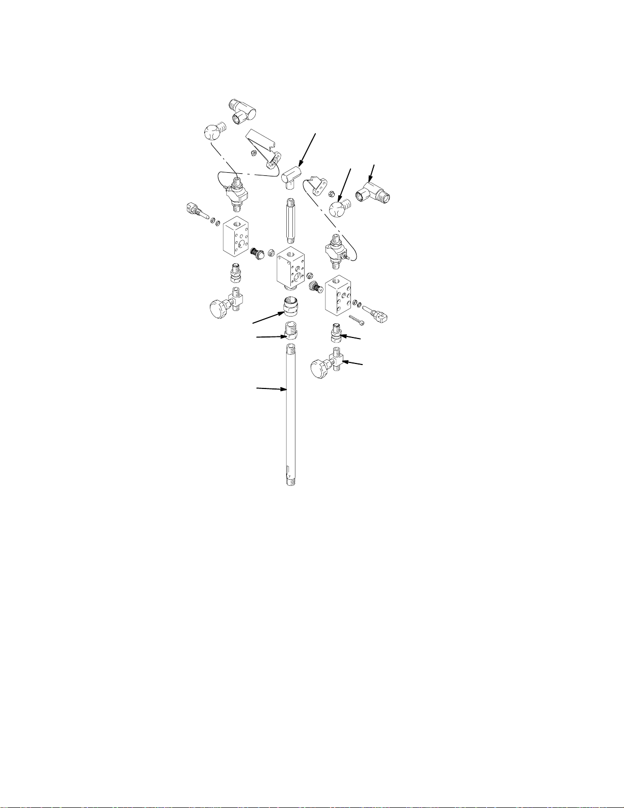
Model 241692 Series A
Parts
9
7
2
4
3
5
8
Ref
No. Part No. Description Qty.
1 215626 MANIFOLD, mixer; see full parts
and listing on pages 10 and 11 1
2 157676 UNION, swivel, 90_ 1
3 155699 ELBOW, street 2
4 161037 FITTING, union, adapter 2
6
5765B
Ref
No. Part No. Description Qty.
5 156823 UNION, swivel 2
6 108233 VALVE, needle 2
7 502265 BUSHING, reducer, pipe 1
8 512506 MIXER, static, pipe 1
9 158581 COUPLING, hex 1
12 307400
Page 13

Technical Data
Maximum working pressure 3000 psi (21.0 MPa, 210 bar). . . . . . . . . . . . . . . . . . . . .
Fluid port size
Model 215625 1/4 npt(m). . . . . . . . . . . . . . . . . . . . . . . . . . . . . . . . . . . . . . . . . . . . . . .
Model 241692 1/2 npt(f). . . . . . . . . . . . . . . . . . . . . . . . . . . . . . . . . . . . . . . . . . . . . . .
Model 215626 3/8 npt(m). . . . . . . . . . . . . . . . . . . . . . . . . . . . . . . . . . . . . . . . . . . . . . .
Solvent port size
Model 215625 1/4 npt(m). . . . . . . . . . . . . . . . . . . . . . . . . . . . . . . . . . . . . . . . . . . . . . .
Model 215626 and 241692 1/4 npt(m). . . . . . . . . . . . . . . . . . . . . . . . . . . . . . . . . . . .
Fluid outlet size
Model 215625 1/4 npt(m). . . . . . . . . . . . . . . . . . . . . . . . . . . . . . . . . . . . . . . . . . . . . . .
Model 241692 3/8 npt(m). . . . . . . . . . . . . . . . . . . . . . . . . . . . . . . . . . . . . . . . . . . . . . .
Model 215626 1/2 npt(m). . . . . . . . . . . . . . . . . . . . . . . . . . . . . . . . . . . . . . . . . . . . . . .
Mix chamber volume
Model 215625 0.10 fluid oz. (3.1 ml). . . . . . . . . . . . . . . . . . . . . . . . . . . . . . . . . . . . .
Model 215626 and 241692 0.32 fluid oz. (10 ml). . . . . . . . . . . . . . . . . . . . . . . . . . .
Wetted parts Chrome Alloy, High Carbon, Nickel . . . . . . . . . . . . . . . . . . . . . . . . . . . . .
Plated and Zinc Plated Steels; 303,
Delrin
NylatronR is a registered trademark of the Polymer Corporation.
316*, and 416 stainless steels; Delrin
Nylon, PTFE,
RR
is a registered trademarks of the DuPont Company.
R
Plastics and Nylatron
*316 Stainless Steel only used in 216626.
R
,
R
13307400
Page 14

Dimensions
A
Overall Length
B
Overall Height
C
Overall Width
D
Fluid Inlets
E
Solvent Inlet
F
Material Outlet
E
Model
215625
5.0 in
(127 mm)
5.375 in.
(136 mm)
1.375 in
(35 mm)
1/4 npt(m) 3/8 npt(m) 3/8 npt(m)
1/4 npt(m) 1/4 npt(m) 1/4 npt(m)
1/4 npt(m) 1/2 npt(m) 3/8 npt(m)
Model
215626
5.5 in
(140 mm)
6.25 in
(159 mm)
1.25 in
(32 mm)
Model
241692
5.5 in
(140 mm)
19.85 in
(504 mm)
1.25 in
(32 mm)
1/4 npt plugged ports
1
in two end sections of
manifold
Two 0.26” (6.6 mm)
2
D
diameter mounting
holes 1.10” (27.9 mm)
apart center to center.
2
E
D
B
2
B
C
1
1
C
A
F
05764
F
05764B
A
14 307400
Page 15

Notes
head.notes
15307400
Page 16

Graco Standard Warranty
Graco warrants all equipment manufactured by Graco and bearing its name to be free from defects in material and workmanship on the
date of sale by an authorized Graco distributor to the original purchaser for use. With the exception of any special, extended, or limited
warranty published by Graco, Graco will, for a period of twelve months from the date of sale, repair or replace any part of the equipment
determined by Graco to be defective. This warranty applies only when the equipment is installed, operated and maintained in accordance with Graco’s written recommendations.
This warranty does not cover, and Graco shall not be liable for general wear and tear, or any malfunction, damage or wear caused by
faulty installation, misapplication, abrasion, corrosion, inadequate or improper maintenance, negligence, accident, tampering, or substitution of non-Graco component parts. Nor shall Graco be liable for malfunction, damage or wear caused by the incompatibility of
Graco equipment with structures, accessories, equipment or materials not supplied by Graco, or the improper design, manufacture,
installation, operation or maintenance of structures, accessories, equipment or materials not supplied by Graco.
This warranty is conditioned upon the prepaid return of the equipment claimed to be defective to an authorized Graco distributor for
verification of the claimed defect. If the claimed defect is verified, Graco will repair or replace free of charge any defective parts. The
equipment will be returned to the original purchaser transportation prepaid. If inspection of the equipment does not disclose any defect
in material or workmanship, repairs will be made at a reasonable charge, which charges may include the costs of parts, labor, and
transportation.
THIS WARRANTY IS EXCLUSIVE, AND IS IN LIEU OF ANY OTHER WARRANTIES, EXPRESS OR IMPLIED, INCLUDING BUT
NOT LIMITED TO WARRANTY OF MERCHANTABILITY OR WARRANTY OF FITNESS FOR A PARTICULAR PURPOSE.
Graco’s sole obligation and buyer’s sole remedy for any breach of warranty shall be as set forth above. The buyer agrees that no other
remedy (including, but not limited to, incidental or consequential damages for lost profits, lost sales, injury to person or property, or any
other incidental or consequential loss) shall be available. Any action for breach of warranty must be brought within two (2) years of the
date of sale.
Graco makes no warranty, and disclaims all implied warranties of merchantability and fitness for a particular purpose in connection
with accessories, equipment, materials or components sold but not manufactured by Graco. These items sold, but not manufactured
by Graco (such as electric motors, switches, hose, etc.), are subject to the warranty, if any, of their manufacturer. Graco will provide
purchaser with reasonable assistance in making any claim for breach of these warranties.
In no event will Graco be liable for indirect, incidental, special or consequential damages resulting from Graco supplying equipment
hereunder, or the furnishing, performance, or use of any products or other goods sold hereto, whether due to a breach of contract,
breach of warranty, the negligence of Graco, or otherwise.
FOR GRACO CANADA CUSTOMERS
The parties acknowledge that they have required that the present document, as well as all documents, notices and legal proceedings
entered into, given or instituted pursuant hereto or relating directly or indirectly hereto, be drawn up in English. Les parties reconnaissent avoir convenu que la rédaction du présente document sera en Anglais, ainsi que tous documents, avis et procédures judiciaires
exécutés, donnés ou intentés à la suite de ou en rapport, directement ou indirectement, avec les procedures concernées.
Graco Information
TO PLACE AN ORDER, contact your Graco distributor, or call one of the following numbers
to identify the distributor closest to you:
1–800–367–4023 Toll Free
612–623–6921
612–378–3505 Fax
All written and visual data contained in this document reflects the latest product information available at the time of publication.
Graco reserves the right to make changes at any time without notice.
16 307400
International Offices: Belgium, Korea, Hong Kong, Japan
Sales Offices: Minneapolis, Detroit
GRACO INC. P.O. BOX 1441 MINNEAPOLIS, MN 55440–1441
www.graco.com
PRINTED IN U.S.A. 307400 09/1980, Revised 10/2002
 Loading...