

Page 1
Instructions–Parts List
HIGH PRESSURE
Surge Tanks and
Fluid Filters
For fluid surge reduction and for filtering of finishing materials.
Important Safety Instructions
Read all warnings and instructions in this manual.
Save these instructions.
Fluid Filters
5000 psi (350 bar, 35 MPa) Maximum Working Pressure
307296T
EN
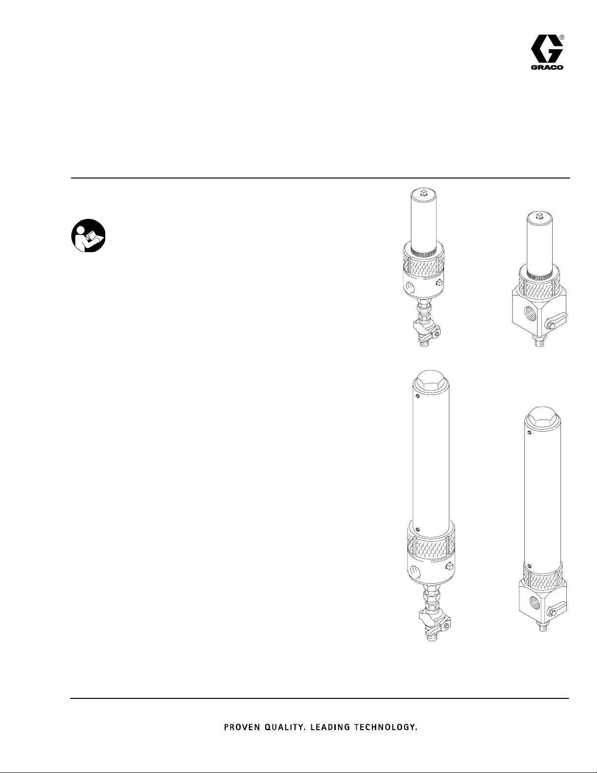
Model 238620, Series A
Exposed Mounting
Model 214724, Series E
Cover Mounting
Model 289310, Series A
Cover Mounting
Fluid Filter
7252 psi (500 bar, 50 MPa) Maximum Working Pressure
Model 237069, Series A
Exposed Mounting
Surge Tanks (with filter)
5000 psi (350 bar, 35 MPa) Maximum Working Pressure
Model 214624, Series C
Exposed Mounting
Model 238623, Series A
Exposed Mounting
Model 214726, Series E
Cover Mounting
Fluid Filter,
Exposed
Mounting
Fluid Filter,
Cover
Mounting
1008 1009
Mastic Surge Tanks (without filter)
5000 psi (350 bar, 35 MPa) Maximum Working Pressure
Model 214623, Series A
Exposed Mounting; for use with high viscosity fluids
Model 214725, Series C
Covered Mounting; for use with low to medium viscosity fluids
Surge Tank,
Exposed
Mounting
1008
Surge Tank,
Cover
Mounting
1005
Page 2
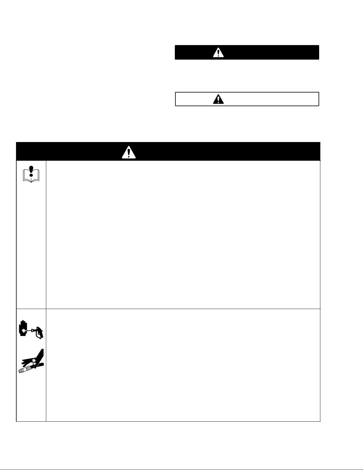
Table of Contents
Symbols
Warnings 2. . . . . . . . . . . . . . . . . . . . . . . . . . . . . . . . . . . . . .
Installation 3. . . . . . . . . . . . . . . . . . . . . . . . . . . . . . . . . . . . .
Surge Tank Conversion Kits 4. . . . . . . . . . . . . . . . . . . . .
Operation 5. . . . . . . . . . . . . . . . . . . . . . . . . . . . . . . . . . . . .
Service 6. . . . . . . . . . . . . . . . . . . . . . . . . . . . . . . . . . . . . . .
Parts 7. . . . . . . . . . . . . . . . . . . . . . . . . . . . . . . . . . . . . . . . .
Accessories 13. . . . . . . . . . . . . . . . . . . . . . . . . . . . . . . . . .
Technical Data 14. . . . . . . . . . . . . . . . . . . . . . . . . . . . . . . .
Mounting Hole Layout 14. . . . . . . . . . . . . . . . . . . . . . . . . .
Dimensions 15. . . . . . . . . . . . . . . . . . . . . . . . . . . . . . . . . . .
Warranty 16. . . . . . . . . . . . . . . . . . . . . . . . . . . . . . . . . . . . .
Graco Information 16. . . . . . . . . . . . . . . . . . . . . . . . . . . . .
WARNING
EQUIPMENT MISUSE HAZARD
Equipment misuse can cause the equipment to rupture or malfunction and result in serious injury.
INSTRUCTIONS
D This equipment is for professional use only.
D Read all instruction manuals, tags, and labels before operating the equipment.
Warning Symbol
WARNING
This symbol alerts you to the possibility of serious
injury or death if you do not follow the instructions.
Caution Symbol
CAUTION
This symbol alerts you to the possibility of damage to
or destruction of equipment if you do not follow the
instructions.
D Use the equipment only for its intended purpose. If you are not sure, call your Graco distributor.
D Do not alter or modify this equipment.
D Check equipment daily. Repair or replace worn or damaged parts immediately.
D Do not exceed the maximum working pressure of the lowest rated system component. Refer to the
Technical Data on page 14 for the maximum working pressure of this equipment.
D Use fluids and solvents which are compatible with the equipment wetted parts. Refer to the Tech-
nical Data section of all equipment manuals. Read the fluid and solvent manufacturer’s warnings.
D Comply with all applicable local, state, and national fire, electrical, and safety regulations.
SKIN INJECTION HAZARD
Spray from the gun, leaks or ruptured components can inject fluid into your body and cause extremely
serious injury, including the need for amputation. Fluid splashed in the eyes or on the skin can also
cause serious injury.
D Fluid injected into the skin might look like just a cut, but it is a serious injury. Get immediate surgi-
cal treatment.
D Do not stop or deflect leaks with your hand, body, glove or rag.
D Follow the Pressure Relief Procedure on page 6 before cleaning, checking or servicing the
equipment.
D Tighten all fluid connections before operating the equipment.
3072962
Page 3
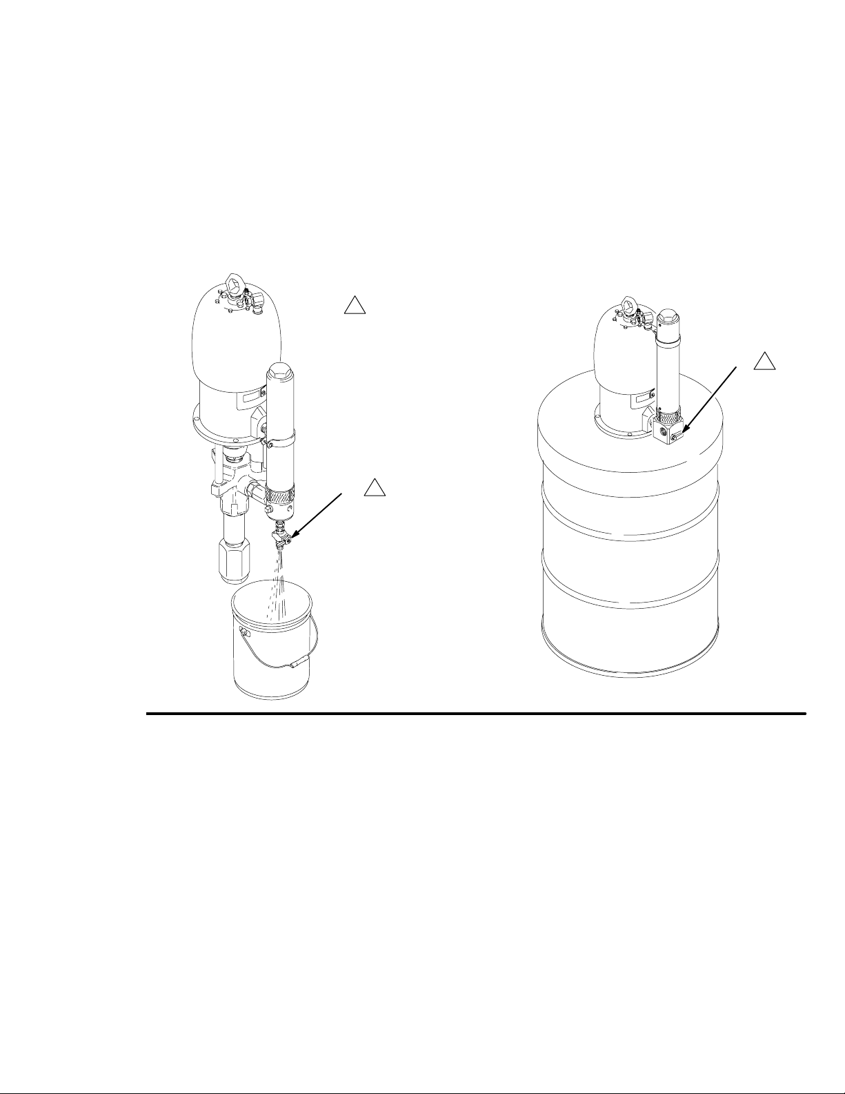
Installation
Typical Mountings
See Fig. 1 for typical mountings. See page 14 for the
mounting hole layout.
Install the surge tank or filter near the pump outlet.
Position the surge tank so the labels face away from
the pump and so the setscrews, near the top and
bottom of the tank, face toward the pump.
Exposed Mountings
Detail A: With Riser Tube
The top of the surge tank must always be supported.
See Accessories on page 13 for mounting clamps.
Surge tanks must always be mounted upright, as
shown in Fig. 1, not horizontally.
Detail B: No Riser Tube
Detail C: Integral Riser Tube
Fig. 1
05910
Drum Cover Mountings
Detail D: Separate Riser Tube
05912
307296 3
Page 4
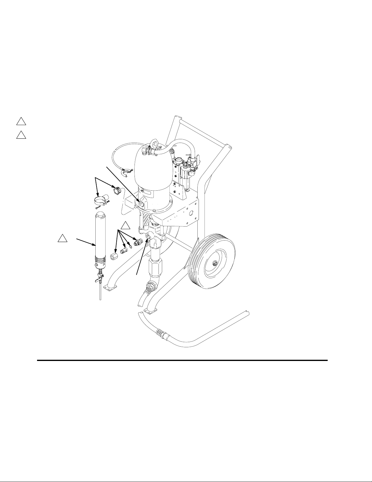
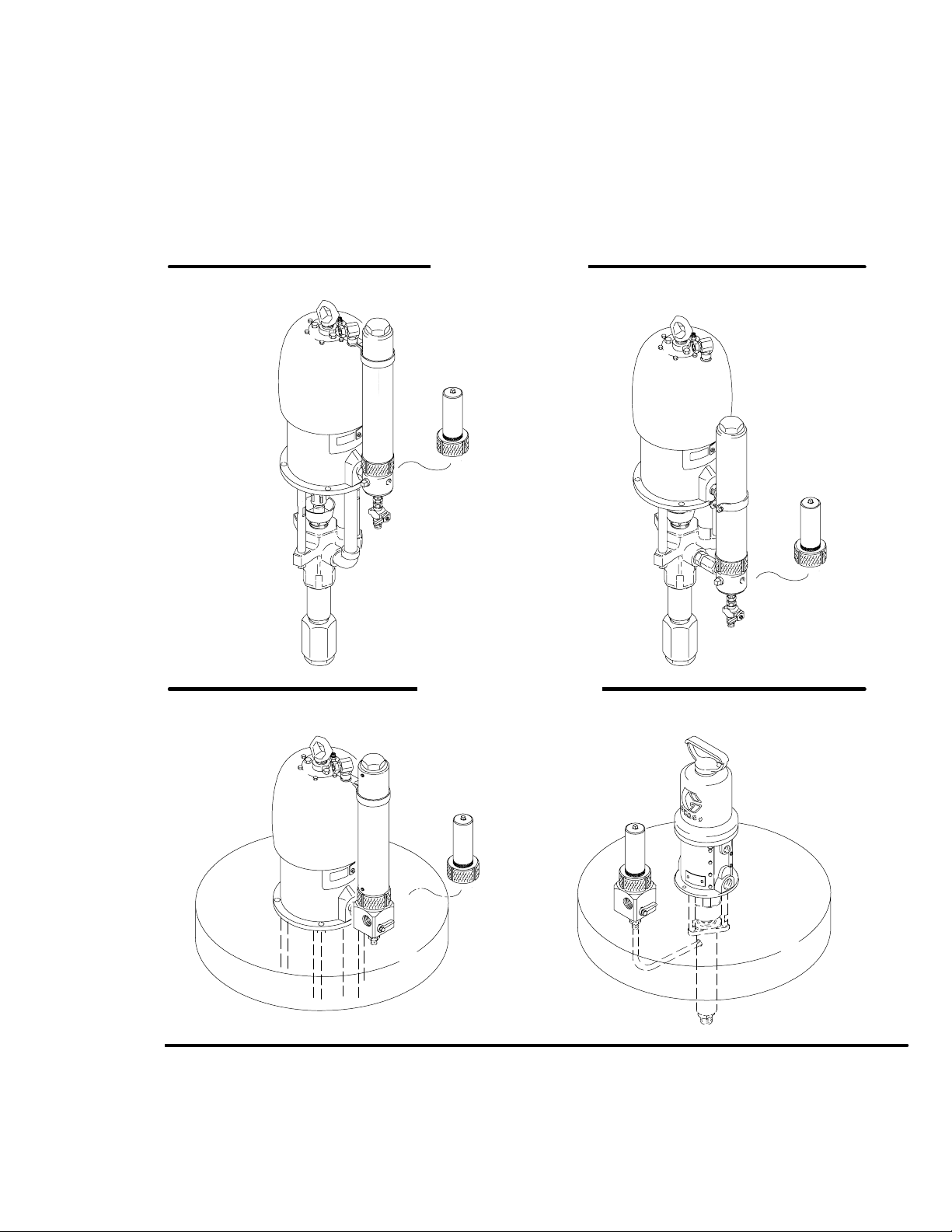
Surge Tank Conversion Kits
Surge Tank Conversion Kits 238634 and
237704
Use Conversion Kits 238634 or 237704 to add a surge
tank to a pump. Kit 238634 includes surge tank
238623 (A) and clamp 238630 (B). Kit 237704 includes
surge tank 214624 (A), clamp 238630 (B), and attaching hardware (C).
1
These parts are included with Conversion Kit 237704 only.
2 Model 238623 Surge Tank shown.
E
B
Connect the surge tank to the fluid outlet (F) of the
displacement pump and install the clamp in the optional outlet (E) at the base of the air motor. See Fig. 2.
Fig. 2
C
1
A
2
F
05927
3072964
Page 5
Operation
Before operating the equipment, be sure the drain
valve is closed.
Flush the equipment with a compatible solvent to
remove oil used for factory testing and rust prevention.
If you notice excessive surging at the spray gun, shut
off the pump, trigger the gun to relieve fluid pressure,
and open the drain valve (D) at the bottom of the surge
tank. See Fig. 3. After the tank is drained, close the
drain valve and resume operation.
1
Open drain valve to relieve pressure.
1
D
Be sure the drain valve is fully closed when spraying
and fully open when draining or circulating fluid to get
the best results and reduce wear on the valve.
1
D
Fig. 3
0591305911
307296 5
Page 6

Service
Pressure Relief Procedure
WARNING
SKIN INJECTION HAZARD
The system pressure must be manually
relieved to prevent the system from
starting or spraying accidentally. Fluid
under high pressure can be injected through the
skin and cause serious injury. To reduce the risk of
an injury from injection, splashing fluid, or moving
parts, follow the Pressure Relief Procedure
whenever you:
D are instructed to relieve the pressure,
D stop spraying,
D check or service any of the system equipment,
D or install or clean the spray tips.
1. Lock the gun trigger safety.
2. Turn off the power to the pump.
3. Close any master bleed-type air valves.
Service Notes
Clean all parts thoroughly when disassembling. Check
parts carefully for damage or wear, replace as needed.
Numbers in parentheses in the text refer to the parts
drawings.
Check periodically for leakage from the small holes
near the top and bottom of the surge tanks. If you find
leakage at the holes or anywhere else, replace the
seals promptly.
Before removing the end plug and adapter from the
surge tank, loosen the setscrews (5) near the bottom
of the tank (6). See the parts drawings on pages 7
through 12.
Inspect the sealing surfaces for nicks or scratches that
might cause leakage. Do not damage the sealing
surfaces.
When reassembling filters after cleaning or servicing,
be sure to install the filter support as shown in the
parts drawings. Do not install it upside down.
4. Unlock the gun trigger safety.
5. Hold a metal part of the gun firmly to the side of a
grounded metal pail, and trigger the gun to relieve
pressure.
6. Lock the gun trigger safety.
7. Place a pail under the drain valve, and open the
drain valve to be sure all fluid pressure is relieved.
Keep hands away from the end of the drain valve
when opening it.
8. Leave the drain valve open until you are ready to
spray again.
If you suspect that the spray tip or hose is completely
clogged, or that pressure has not been fully relieved
after following the steps above, very slowly loosen the
tip guard retaining nut or hose end coupling and relieve
pressure gradually, then loosen completely. Now clear
the tip or hose.
WARNING
Tighten all threaded connections securely. High
pressure fluid can dislodge a loose connection or
allow high pressure fluid to be emitted from the
connection and cause serious injury.
3072966
Page 7

Parts
Model 214724, Series E
Model 289310, Series A
Includes items 1–25
See Accessories for other available screens.
1
1
2
Replace filter support if ridges are worn down.
2
3
Lubricate.
Do not damage PTFE o-ring (7). Lubricate and
4
bend into kidney shape, then push into groove.
3
4
1
5
24
23
10
Ref
No. Part No. Description Qty
1 174058 RING, lock 1
2 104813 PLUG, pipe, 3/8 npt 1
3n 174056 BOWL, filter 1
4 171941 SPRING, conical compression 1
5 167025 STRAINER, 60 mesh (Model 214724) 1
167024 STRAINER, 30 mesh (Model 289310) 1
6 186075 SUPPORT, filter 1
7n 104804 PACKING, o-ring, PTFE 1
10 104839 PLUG, pipe, 1/2 npt 1
11 102291 PIN, drive 2
12 164900 WASHER, flat 2
13 175043 LEVER 1
14 103337 PACKING, o-ring, fluoroelastomer 1
2
6
14
12
11
7
4
25
3
18
19
20
21
15
12
16
13
17
22
1007
Ref
No. Part No. Description Qty
15 166697 STEM, valve 1
16 165964 NUT, packing 1
17 102310 NUT, acorn, no. 10–32 1
18 172094 SEAT, ball 1
19 165273 BALL, valve 1
20 206481 SEAT, valve 1
21 103648 PACKING, o-ring, fluoroelastomer 1
22 165274 NIPPLE, adapter 1
23 104663 PLUG, pipe, 3/4 npt 1
24 174080 MANIFOLD 1
25 101754 PLUG, pipe, 3/8 npt 1
n Keep these spare parts on hand to reduce down time.
307296 7
Page 8

Model 238620, Series A
Includes items 1–28
See Accessories for other available screens.
1
2
Replace filter support if ridges are worn down.
3
Lubricate.
Do not damage PTFE o-ring (7). Lubricate and
4
bend into kidney shape, then push into groove.
Parts
1
2
8
2
3
4
5
1
10
2
26
9
27
2
6
7
3
4
Ref
No. Part No. Description Qty
1 174058 RING, lock 1
2 104813 PLUG, pipe, 3/8 npt 3
3n 174056 BOWL, filter 1
4 171941 SPRING, conical compression 1
5 167025 STRAINER, 60 mesh 1
6 186075 SUPPORT, filter 1
7n 104804 PACKING, o-ring, PTFE 1
8 24C497 MANIFOLD, paint filter 1
28
05908
Ref
No. Part No. Description Qty
9 223960 BALL VALVE, see 306861 for parts 1
10 104839 PLUG, pipe, 1/2 npt 1
26 155665 UNION, adapter 1
27 205448 COUPLING, swivel; 3/8 npsm(f) 1
28 186447 TUBE, drain; nylon;
1/4 in. (0.6 mm) ID; 5 in. (127 mm) 1
n Keep these spare parts on hand to reduce down time.
3072968
Page 9

Model 237069
Includes items 1–26
See Accessories for other available screens.
1
2
Replace filter support if ridges are worn down.
3
Lubricate.
Do not damage PTFE o-ring (7). Lubricate and
4
bend into kidney shape, then push into groove.
Parts
8
1
2
3
4
5
1
2
26
9
Ref
No. Part No. Description Qty
10
2
6
2
7
3
4
Ref
No. Part No. Description Qty
05909
1 174058 RING, lock 1
2 104813 PLUG, pipe, 3/8 npt 3
3n 174056 BOWL, filter 1
4 171941 SPRING, conical compression 1
5 167025 STRAINER, 60 mesh 1
6 186075 SUPPORT, filter 1
7n 104804 PACKING, o-ring, PTFE 1
8 24C497 MANIFOLD, paint filter 1
9 224774 DRAIN VALVE 1
10 100737 PLUG, pipe, 1/2 npt 1
26 156296 NIPPLE; 3/8 npt x 1/8 npt 1
n Keep these spare parts on hand to reduce down time.
307296 9
Page 10
Parts
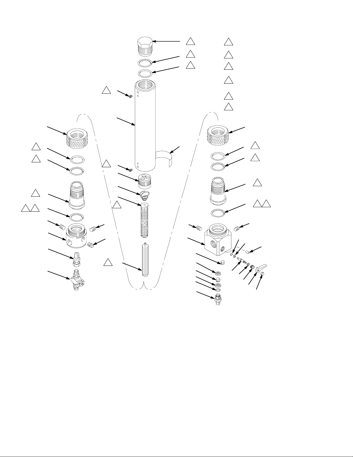
Model 214624, Series C
Includes items 1–16, 31, 33, 34
Model 214726, Series E
Includes items 1–13, 17–32, 34
11
3
3
3
2
12
5
13
4
3
1
5
3
2
3
3
5
6
See Accessories for other
1
available screens.
Replace filter support if
2
ridges are worn down.
3
Lubricate.
Do not damage PTFE o-ring (13).
4
Lubricate and bend into kidney
shape, then push into groove.
Torque to 150 ft–lb (200 N.m).
5
Torque to 40 in–lb (4.5 N.m).
6
6
11
34
6
5
3
3
2
3
7
12
8
5
9
13
3
1
4
15
31
14
15
33
10
2
16
Ref
No. Part No. Description Qty
1 174064 PLUG, end 1
2n 104805 RING, backup, PTFE 2
3n 166612 PACKING, o-ring, PTFE 2
5 111463 SETSCREW,1/4–20 x 3/8” 2
6 none TANK, accumulator not sold separately 1
7 174059 ADAPTER, filter 1
8 171941 SPRING, conical compression 1
9 167025 STRAINER, 60 mesh 1
10 186075 SUPPORT, filter 1
11 174058 RING, lock 1
12n 174068 ADAPTER, accumulator 1
13n 104804 PACKING, o-ring, PTFE 1
14 24C497 MANIFOLD, paint filter 1
15 104813 PLUG, pipe, 3/8 npt 2
16 210658 BALL VALVE, see 306861 for parts 1
17 164900 WASHER, flat 2
18 175043 LEVER 1
19 103337 PACKING, o-ring, fluoroelastomer 1
20 166697 STEM, valve 1
30729610
19
17
31
32
30
23
24
25
26
27
28
29
Ref
No. Part No. Description Qty
21 165964 NUT, packing 1
22 102310 NUT, acorn, No. 10–32 1
23 174080 MANIFOLD 1
24 101754 PLUG, pipe, 3/8 npt 1
25 172094 SEAT, ball 1
26 165273 BALL, valve 1
27 206481 SEAT, valve 1
28 103648 PACKING, o-ring, fluoroelastomer 1
29 165274 NIPPLE, adapter 1
30 104663 PLUG, pipe, 3/4 npt 1
31 104839 PLUG, 1/2 npt 1
32 102291 PIN, drive 2
33 155665 UNION, adapter 1
34Y 169579 LABEL, warning 1
n Keep these spare parts on hand to reduce down time.
Y Replacement Danger and Warning labels, tags and cards
are available at no cost.
20
17
21
18
22
1004
Page 11

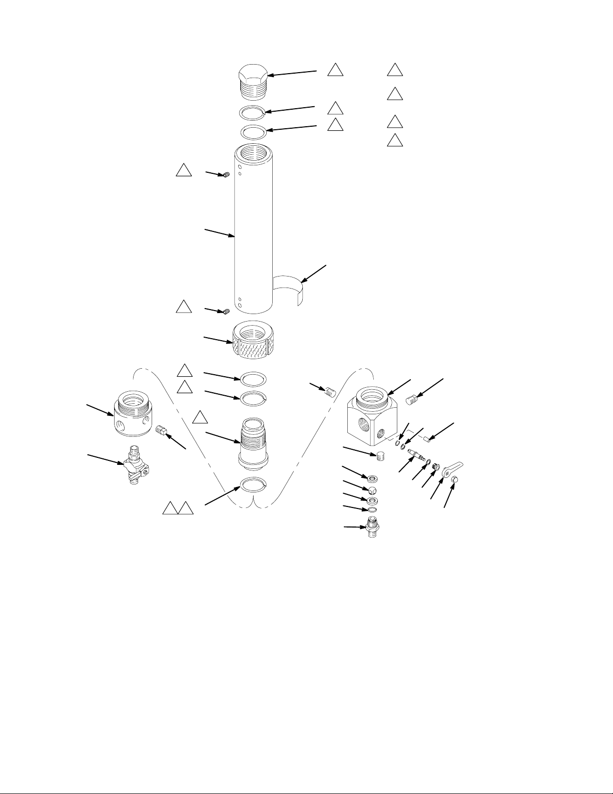
Parts
Model 238623, Series A
Includes items 1–36
See Accessories for other
1
available screens.
Replace filter support if
2
ridges are worn down.
3
Lubricate.
Do not damage PTFE o-ring (13).
4
Lubricate and bend into kidney
shape, then push into groove.
Torque to 150 ft–lb (200 N.m).
5
Torque to 40 in–lb (4.5 N.m).
6
1
5
3
2
3
3
5
6
11
3
2
3
3
6
5
12
4
3
34
15
6
5
7
14
13
31
15
8
33
9
1
10
2
Ref
No. Part No. Description Qty
1 174064 PLUG, end 1
2n 104805 RING, backup, PTFE 2
3n 166612 PACKING, o-ring, PTFE 2
5 111463 SETSCREW,1/4–20 x 3/8” 2
6 none TANK, accumulator not sold separately 1
7 174059 ADAPTER, filter 1
8 171941 SPRING, conical compression 1
9 167025 STRAINER, 60 mesh 1
10 186075 SUPPORT, filter 1
11 174058 RING, lock 1
12n 174068 ADAPTER, accumulator 1
13n 104804 PACKING, o-ring, PTFE 1
14 24C497 MANIFOLD, paint filter 1
16
35
36
05907
Ref
No. Part No. Description Qty
15 104813 PLUG, pipe, 3/8 npt 2
16 238612 BALL VALVE, see 306861 for parts 1
31 104839 PLUG, 1/2 npt 1
33 155665 UNION, adapter 1
34Y 169579 LABEL, warning 1
35 205448 COUPLING, swivel; 3/8 npsm(f) 1
36 186447 TUBE, drain; nylon;
1/4 in. (0.6 mm) ID; 5 in. (127 mm) 1
n Keep these spare parts on hand to reduce down time.
Y Replacement Danger and Warning labels, tags and cards
are available at no cost.
307296 11
Page 12
Parts
Model 214623, Series A
Includes items 1–12, 29
Model 214725, Series C
Includes items 1–9, 11, 13–29
5
1
2
3
3
3
5
6
3
Lubricate.
Do not damage PTFE o-ring (9).
4
Lubricate and bend into kidney
shape, then push into groove.
Torque to 150 ft–lb (200 N.m).
5
Torque to 40 in–lb (4.5 N.m).
6
6
29
5
6
7
3
3
3
2
10
5
8
12
Ref
No. Part No. Description Qty
1 174064 PLUG, end 1
2n 104805 RING, backup, PTFE 2
3n 166612 PACKING, o-ring, PTFE 2
5 111463 SETSCREW, 1/4–20 x 3/8” 2
6 none TANK, accumulator not sold separately 1
7 174058 RING, lock 1
8 174068 ADAPTER, accumulator 1
9n 104804 PACKING, o-ring, PTFE 1
10 174060 MANIFOLD, accumulator 1
11 104663 PLUG, pipe, 3/4 npt 1
12 210658 BALL VALVE, see 306861 for parts 1
13 175043 LEVER 1
14 104839 PLUG, 1/2 npt 1
15 103337 PACKING, o-ring, fluoroelastomer 1
16 166697 STEM, valve 1
17 165964 NUT, packing 1
11
9
3
4
30729612
28
14
27
11
19
15
20
21
22
23
24
16
28
17
13
18
25
Ref
No. Part No. Description Qty
18 102310 NUT, acorn, No. 10–32 1
19 174080 MANIFOLD 1
20 101754 PLUG, pipe, 3/8 npt 1
21 172094 SEAT, ball 1
22 165273 BALL, valve 1
23 206481 SEAT, valve 1
24 103648 PACKING, o-ring, fluoroelastomer 1
25 165274 NIPPLE, adapter 1
27 102291 PIN, drive 2
28 164900 WASHER, flat 2
29Y 169579 LABEL, warning 1
n Keep these spare parts on hand to reduce down time.
Y Replacement Danger and Warning labels, tags and cards
are available at no cost.
1006
Page 13
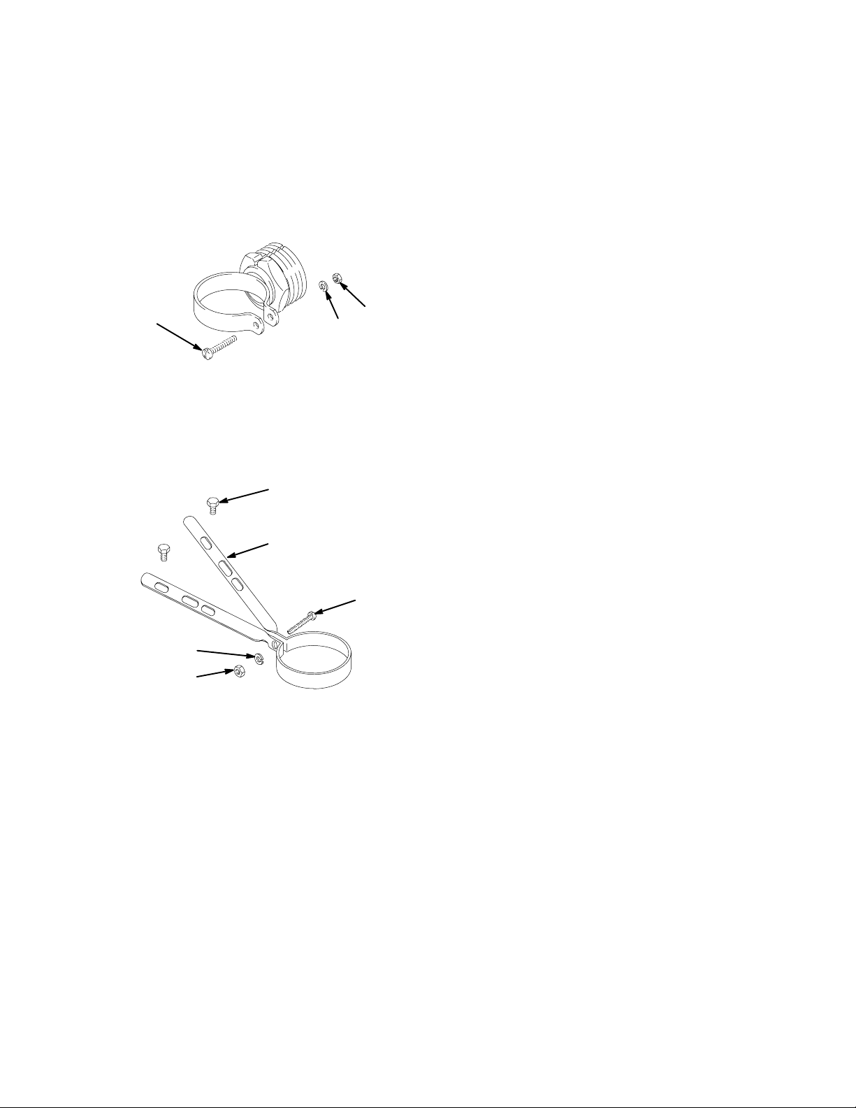
Accessories
Use Only Genuine Graco Parts and Accessories
SURGE TANK CLAMPS
238630
For surge tanks mounted in the fluid outlet of the
displacement pump. Install the clamp in the optional
outlet at the base of the air motor. Requires 100902
screw, 100016 lockwasher and 100015 nut.
100902
100016
172865
For surge tanks mounted in the optional fluid outlet of
Bulldog or King pumps when used with a riser tube.
Attach the clamp to the top of the air motor shield.
Requires 100902 screw, 100016 lockwasher, 100015
nut, and two 100270 screws.
100270
100015
PTFE SEALS
For ball valves and drain valves.
104892 to replace 103648 fluoroelastomer seal
104893 to replace 103337 fluoroelastomer seal
STAINLESS STEEL SCREENS
167024 595 micron (30 mesh)
167025 250 micron (60 mesh)
167026 149 micron (100 mesh)
167027 75 micron (200 mesh)
100016
100015
172865
100902
307296 13
Page 14

Technical Data
Mounting Hole
Category Data
Maximum
Working
Pressure
Weight Model 214623: 30 lb (13 kg)
Surge Tank
Volume
Filter Area 18 in2 (120 cm
Wetted Parts Stainless steel, zinc-plated steel,
Model 237069: 7252 psi (500 bar, 50
MPa)
All Other Models: 5000 psi (350 bar,
35 MPa)
Model 214624: 31.5 lb (14 kg)
Model 214724: 13 lb (6 kg)
Model 214725: 34 lb (15 kg)
Model 214726: 34 lb (15 kg)
Model 237069: 10.5 lb (4.5 kg)
Model 238620: 10.5 lb (4.5 kg)
Model 238623: 31.5 lb (14 kg)
Model 289310: 13 lb (6 kg)
15 oz. (450 ml)
2)
nylon, PTFE, fluoroelastomer
Layout
For mounting square base surge tanks and filters on a
drum cover or other support.
2.38”
(60 mm) dia.
1.06”
(27 mm)
0.312”
1.06” (27 mm)
(8.12 mm) dia.
30729614
Page 15

A*
Dimensions
* For models 238620 and 238623, add approximately 6 in. (152 mm) to
the “A” dimension to account for the drain tube and fitting.
C
B
C
B
A*
D
D
K
F
J
E
L
G
Filters Paint Surge Tanks Mastic Surge Tanks
Dimensions 238620 237069
A
(see * note
above)
B 8.75 in.
C 2.06 in.
D 3.12 in.
E 3.00 in.
Inlets
11.63 in.
(295 mm)
(222 mm)
(52 mm) dia.
(79 mm) dia.
(76 mm) dia.
11.50 in.
(292 mm)
8.75 in.
(222 mm)
2.06 in.
(52 mm) dia.
3.12 in.
(79 mm) dia.
3.00 in.
(76 mm) dia.
214724 &
289310
10.38 in.
(265 mm)
9.62 in.
(245 mm)
2.06 in.
(52 mm) dia.
3.12 in.
(79 mm) dia.
3.00 in.
(76 mm) dia.
1005
(76 mm) dia.
(79 mm) dia.
(76 mm) dia.
214624 &
238623
23.00 in.
(585 mm)
20.12 in.
(510 mm)
3.00 in.
3.12 in.
3.00 in.
K
H
F
E
L
214726 214623 214725
21.75 in.
(550 mm)
21.00 in.
(535 mm)
3.00 in.
(76 mm) dia.
3.12 in.
(79 mm) dia.
3.00 in.
(76 mm) dia.
22.75 in.
(578 mm)
19.88 in.
(510 mm)
3.00 in.
(76 mm) dia.
3.12 in.
(79 mm) dia.
3.00 in.
(76 mm) dia.
21.75 in.
(550 mm)
21.00 in.
(535 mm)
3.00 in.
(76 mm) dia.
3.12 in.
(79 mm) dia.
3.00 in.
(76 mm) dia.
J
1008
F 3/4 npt(f) 3/4 npt(f) 3/4 npt(f) 3/4 npt(f) 3/4 npt(f) 3/4 npt(f) 3/4 npt(f)
G 3/8 npt(f) 3/8 npt(f) 3/8 npt(f)
Outlets
H 3/8 npt(f) 3/8 npt(f) 3/8 npt(f) 3/4 npt(f)
J 1/2 npt(f) 1/2 npt(f) 1/2 npt(f) 1/2 npt(f) 1/2 npt(f) 3/4 npt(f) 1/2 npt(f)
K 3/8 npt(f) 3/8 npt(f) 3/4 npt(f) 3/8 npt(f) 3/4 npt(f) 3/4 npt(f)
Drain
L 3/8 npt(m) 1/8 npt(f) 1/4 npt(m) 3/8 npt(f) 1/4 npt(m) 3/8 npt(f) 1/4 npt(m)
Mtg. Holes
M(2) 1/4–20 1/4–20 1/4–20
307296 15
Page 16

The Graco Standard Warranty
Graco warrants all equipment manufactured by Graco and bearing its name to be free from defects in material and workmanship on the
date of sale to the original purchaser for use. With the exception of any special, extended, or limited warranty published by Graco,
Graco will, for a period of twelve months from the date of sale, repair or replace any part of the equipment determined by Graco to be
defective. This warranty applies only when the equipment is installed, operated and maintained in accordance with Graco’s written
recommendations.
This warranty does not cover, and Graco shall not be liable for general wear and tear, or any malfunction, damage or wear caused by
faulty installation, misapplication, abrasion, corrosion, inadequate or improper maintenance, negligence, accident, tampering, or substitution of non–Graco component parts. Nor shall Graco be liable for malfunction, damage or wear caused by the incompatibility of
Graco equipment with structures, accessories, equipment or materials not supplied by Graco, or the improper design, manufacture,
installation, operation or maintenance of structures, accessories, equipment or materials not supplied by Graco.
This warranty is conditioned upon the prepaid return of the equipment claimed to be defective to an authorized Graco distributor for
verification of the claimed defect. If the claimed defect is verified, Graco will repair or replace free of charge any defective parts. The
equipment will be returned to the original purchaser transportation prepaid. If inspection of the equipment does not disclose any defect
in material or workmanship, repairs will be made at a reasonable charge, which charges may include the costs of parts, labor, and
transportation.
THIS WARRANTY IS EXCLUSIVE, AND IS IN LIEU OF ANY OTHER WARRANTIES, EXPRESS OR IMPLIED, INCLUDING BUT
NOT LIMITED TO WARRANTY OF MERCHANTABILITY OR WARRANTY OF FITNESS FOR A PARTICULAR PURPOSE.
Graco’s sole obligation and buyer’s sole remedy for any breach of warranty shall be as set forth above. The buyer agrees that no other
remedy (including, but not limited to, incidental or consequential damages for lost profits, lost sales, injury to person or property, or any
other incidental or consequential loss) shall be available. Any action for breach of warranty must be brought within two (2) years of the
date of sale.
Graco makes no warranty, and disclaims all implied warranties of merchantability and fitness for a particular purpose in connection
with accessories, equipment, materials or components sold but not manufactured by Graco. These items sold, but not manufactured
by Graco (such as electric motors, switches, hose, etc.), are subject to the warranty, if any, of their manufacturer. Graco will provide
purchaser with reasonable assistance in making any claim for breach of these warranties.
In no event will Graco be liable for indirect, incidental, special or consequential damages resulting from Graco supplying equipment
hereunder, or the furnishing, performance, or use of any products or other goods sold hereto, whether due to a breach of contract,
breach of warranty, the negligence of Graco, or otherwise.
FOR GRACO CANADA CUSTOMERS
The parties acknowledge that they have required that the present document, as well as all documents, notices and legal proceedings
entered into, given or instituted pursuant hereto or relating directly or indirectly hereto, be drawn up in English. Les parties reconnaissent avoir convenu que la rédaction du présente document sera en Anglais, ainsi que tous documents, avis et procédures judiciaires
exécutés, donnés ou intentés à la suite de ou en rapport, directement ou indirectement, avec les procedures concernées.
Graco Information
For the latest information about Graco products, visit www.graco.com.
TO PLACE AN ORDER, contact your Graco distributor, or call one of the following numbers
to identify the distributor closest to you:
1–800–328–0211 Toll Free
612–623–6921
612–378–3505 Fax
All written and visual data contained in this document reflects the latest product information available at the time of publication.
Graco reserves the right to make changes at any time without notice.
For patent information, see www.graco.com/patents.
Original instructions. This manual contains English. MM 307296
International Offices: Belgium, China, Japan, Korea
Graco Headquarters: Minneapolis
GRACO INC. AND SUBSIDIARIES S P.O. BOX 1441 S MINNEAPOLIS MN 55440–1441 S USA
Copyright 1978, Graco Inc. All Graco manufacturing locations are registered to ISO 9001.
www.graco.com
Revised April 2013
30729616
 Loading...