

Page 1
INSTRUCTIONS–P
This
manual contains IMPORT
W
ARNINGS AND INSTRUCTIONS
READ AND RET
AIN FOR REFERENCE
ARTS LIST
ANT
55 Gallon (200 Liter) Drum Size
306–934
Rev. K
Supersedes H
AIR–POWERED
150
psi (10.5 bar) MAXIMUM INBOUND AIR PRESSURE
RAM
Model 207–279, Series J
For
use with high pressure extrusion pumps (see page 3).
Model 223–634, Series A
For
use with Check–Mate 450 pumps
with Displacement Pump 222–790 (see page 3).
TABLE OF CONTENTS
Safety Warnings 2.
Pump
Selection Chart3. . . . . . . . . . . . . . . . . . . . . .
Installation 4–6
Operation 7
Troubleshooting
Service 9–12
Parts
Model 207–279 14, 15
Model
Accessories 18
Dimensional
Technical
Warranty Back
Toll–Free
. . . . . . . . . . . . . . . . . . . . . . . . . . . . . . . .
. . . . . . . . . . . . . . . . . . . . . . . . . . . . . .
Drawings and Lists
223–634 16, 17
Data
.
. . . . . . . . . . . . . . . . . . . . . .
Graco Phone Numbers
. . . . . . . . . . . . . . . . . . . . . . . . .
. . . . . . . . . . . . . . . . . . . . . . . . . . . .
Chart8. . . . . . . . . . . . . . . . . . . . .
.
. . . . . . . . . . . . . . . . . .
.
. . . . . . . . . . . . . . . . . .
. . . . . . . . . . . . . . . . . . . . . . . . . . . . .
Drawing
.
. . . . . . . . . . . . . . . . . . . .
. . . . . . . . . . . . . . . . .
.
.
Back Cover
Cover
Back Cover
19.
GRACO INC. P.O. BOX 1441 MINNEAPOLIS, MN 55440–1441
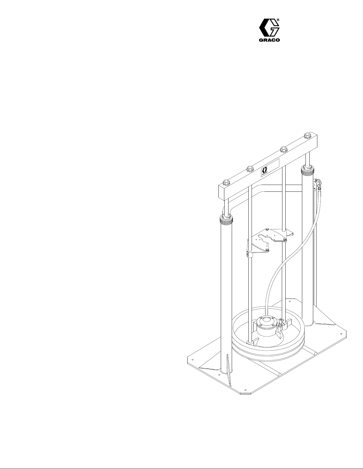
Model
207–279 Shown
Page 2

SAFETY
W
FOR PROFESSIONAL USE ONLY. OBSERVE ALL WARNINGS.
Read and understand all instruction manuals before operating equipment.
EQUIPMENT MISUSE HAZARD
General
Any
ing parts, or using worn or damaged parts, can cause them to rupture and
result
DO
SURE
NEVER
function
CHECK
parts
ALWAYS
instruction
Safety
misuse of the ram or accessories, such as overpressurizing, modify
in serious bodily injury or property damage.
NOT exceed 150 psi (10.5 bar)
to the ram.
alter or modify any part of the ram; doing so could cause it to mal
and make it dangerous to operate.
all equipment regularly and repair or replace worn or damaged
immediately
use the ram only for its intended purpose as
.
manual.
MAXIMUM INBOUND AIR PRES
described in this
-
-
-
ARNINGS
Pressure
To
reduce the risk of serious bodily injury
in the eyes or on the skin, or injury from moving parts, always relieve
ing
all
air and fluid pressure in the system before checking or repairing the
ram
1. Shut
2.
3.
4. T
5.
6. Leave
MOVING PARTS HAZARD
Moving
ram plate/pump fluid inlet moves when the ram is in operation. Keep
hands
fluid container when raising or lowering the ram. Keep clear of all moving
parts when starting or operating the ram or pump. Before checking or
servicing the ram or pump, always follow the Pressure Relief
Procedure,
Relief Procedure
, including fluid injection, splash
or any other part of the system and
of
f the air to the pump and ram.
Open the bleed–type master air valve to relieve trapped air
Shut of
f the ram director valve.
rigger the gun/dispensing valve to relieve fluid pressure.
Open all fluid drain valves in the system.
the drain valves open until you are ready to
again.
parts can pinch or amputate your fingers
and fingers away from the ram plate, pump fluid inlet, and lip of the
above.
when shutting down the system.
.
spray/dispense
or other body parts. The
-
Page 3

For
Pump Model and Description
PUMP SELECTION CHART
Use Ram Model
10:1 Monark, Model 222–770, with Severe–Duty Check–Mate 450 Displacement Pump
20:1 President, Model 222–768, with Severe–Duty Check–Mate 450 Displacement Pump
34:1 Senator
55:1 Bulldog, Model 222–778, with Severe–Duty Check–Mate 450 Displacement Pump
15:1 Senator
15:1 Senator
25:1 Senator
25:1 Senator
10:1 Bulldog, Model 222–526, with Severe–Duty Displacement Pump
10:1 Bulldog, Model 204–287, with Nitralloy Displacement Pump
10:1 Bulldog, Model 207–172, with Stainless Steel Displacement Pump
25:1 Bulldog, Model 222–527, with Severe–Duty Displacement Pump
25:1 Bulldog, Model 217–565, with Nitralloy Displacement Pump
40:1 Bulldog, Model 222–535, with Severe–Duty Displacement Pump
40:1 Bulldog, Model 220–448, with Nitralloy Displacement Pump
, Model 222–769, with Severe–Duty Check–Mate 450 Displacement Pump
, Model 222–518, with Severe–Duty Displacement Pump
, Model 222–489, with Nitralloy Displacement Pump
, Model 222–525, with Severe–Duty Displacement Pump
, Model 222–519, with Nitralloy Displacement Pump
223–634*
223–634*
223–634*
223–634*
207–279
207–279
207–279
207–279
207–279
207–279
207–279
or
954–285**
207–279
207–279
207–279
207–279
20:1 King, Model 222–539, with Severe–Duty Displacement Pump
20:1 King, Model 222–248, with Nitralloy Displacement Pump
20:1 King, Model 220–648, with Stainless Steel Displacement Pump
55:1 King, Model 222–545, with Severe–Duty Displacement Pump
55:1 King, Model 217–566, with Nitralloy Displacement Pump
Mounting Kit 222–776 is required to mount a Check–Mate 450 Pump on Model 223–634 Ram.
*
**
Stainless Steel Ram 954–285 does not include ram plate or tie rods.
NOTE: Model
207–279 Ram is shipped with optional seals (51 and 75), seal plates (76), an intake adapter (55), and
a mounting plate (58) for use with pumps not listed above (see the
installation
Technical
information regarding pumps
Assistance at 1–800–543–0339.
not listed in this chart, contact your Graco representative or Graco
parts
list on page 15). For application and
207–279
207–279
207–279
or
954–285**
207–279
207–279
Page 4

TYPICAL INSTALLATION
26, 27
35
57,
D
J
3
Y
B
A
C
EFG
H
4
66
KEY
A Air
B Bleed–T
C
D
E
F
G Bleed–T
H
J
Y
3
4 Ram Director Valve
26, 27
35 Mounting Bracket Setscrews
57
66
Line Filter
(required, for pump)
ype Master Air V
Pump Air Regulator
Air Manifold
Air Supply Hose (for ram)
Ram Air Regulator
ype Master Air V
(for accessories)
Main Air Supply Line
Drum Clamps
Ground Wire (required)
Support Beam
Pump Mounting Hardware
Pump Mounting Brackets
Air Manifold Mounting Bracket
alve
alve
air–powered ram extruder forces high viscosity flu
This
ids
into the intake valve of the fluid pump. Wiper rings
and
other accessory equipment for use with this ram are
in the ACCESSORIES section.
listed
NOTE: To convert the ram from air to hydraulic opera-
tion, install piston kit 220–501 (see page 18).
Contact
your Graco representative for details.
Locating the Ram
NOTE: Refer
1. Select a convenient location for the equipment.
Check
the pump and ram when the ram is
position. Make sure the air regulators for the pump
and
2.
Level the base of the ram, using metal shims.
3. Using
1/2
anchors which are long enough to prevent the unit
from tipping. Refer to the Dimensional Drawing on
page
4. Mount
procedure
to the Dimensional Drawing on page 19
ram
mounting and clearance dimensions.
that there is suf
ficient overhead clearance
in
the fully raised
ram are fully accessible.
the holes in the base as a guide, drill holes for
in. (13 mm) anchors. Bolt the ram to
the floor with
19.
the pump on the ram, following the applicable
on page 5 or 6.
for
for
-
Installing Accessories and Connecting Air
Lines
1. Install
2. Install
3. Install an air manifold (D) on the mounting bracket
4. Install a second bleed–valve (G) upstream from all
an air line filter (A) on the air supply line to re
move harmful moisture and contaminants from the
compressed
air supply
.
a bleed–type master air valve (B)
from
the pump air regulator (C).
WARNING
bleed–type master air valve (B)
The
is required in
your system to relieve air trapped between this
valve
and the pump after the pump air regulator is
closed. Trapped air can cause the pump to cycle
unexpectedly,
injury,
including splashing in the eyes or on the
and
injury from moving parts.
Connect a suitable air hose (E)
(66).
let
port of the air manifold
which could result in serious bodily
between an out
and the air inlet of the ram
air regulator (F).
accessories,
Connect
to isolate the
accessories for servicing.
the main air supply line (H) to the manifold
(D).
-
downstream
skin
-
Page 5

INSTALLATION
Mounting the Pump (Model 207–279 Ram)
NOTE: The
Mount
tion
on page 4.
1. Remove
those pumps listed in the chart on page 3. Position
the mounting brackets (57) so that the top of the
pump
on the mounting brackets (57) with the air inlet
toward
the mounting brackets with the screws (27) and
washers
2. Remove the four screws (25) and washers (31)
holding
(63)
Leave the bottom seal plate (62) and gasket (61) in
place.
Pump Selection Chart on page
commonly
mounted on this
ram. Installing other
3 lists pumps
pumps on the ram may require alternate parts,
which are packed in separate plastic bags. For
information, contact your Graco representative
or Graco Technical Assistance at
1–800–543–0339.
the pump as follows. Refer to the T
ypical Installa
the mounting plate (58); it is not required
will clear the support beam (3). Set the pump
the ram director valve (4). Attach the pump to
(26) provided.
the standard seal plates (62) to the ram
plate
and remove the top seal plate (62) and seal (56).
See Fig 1.
for
3.
For
15:1 and 25:1 ratio Senator
, 25:1 and 40:1
Bulldog, and 55:1 ratio King standard extrusion
pumps,
slide the top seal plate (62) up over the pump
intake valve and push the seal (56) onto the pump
intake
housing. Then continue with step 4.
For
10:1 ratio Bulldog and 20:1 ratio
a flanged intake housing,
discard the top seal plate
King pumps with
(62) and seal (56). Remove and discard the bottom
-
seal plate (62). Align the holes in the intake valve
flange with those in the gasket (61) and ram plate
(63).
Then continue with step 4.
4. Loosen the mounting bracket setscrews (35), and
carefully
low
5.
If applicable for your installation,
down
lower the pump until the intake valve is
the gasket (61), then tighten the setscrews.
push the seal (56)
firmly against the bottom seal plate (62).
6. Align the holes in the top seal plate or pump intake
flange
(as applicable)
with the holes in the ram plate
(63). Secure tightly to the ram plate with the four
screws
(25) and washers (31).
ratio
be
-
PUMP
62
62
Fig 1
INT
AKE
HOUSING
ST
ANDARD EXTRUSION
PUMPS
56
25, 31
61
63
10:1 BULLDOG AND 20:1 KING PUMPS,
WITH FLANGED INT
AKE HOUSING
INTAKE
HOUSING
FLANGE
25, 31
61
63
306-934ą5
Page 6

INSTALLATION
Mounting the Pump (Model 223–634 Ram)
NOTE: Model
1.
Place the gasket (K) from Mounting Kit 222–776 on
the
ram plate. See Fig 2. Lower the Check–Mate
223–634 Ram is only for use with
Mate 450 Pumps having a 222–790 Displacement
Pump. The Pump Selection Chart on page
3
lists
the Check–Mate 450 Pumps which can be
mounted
This
See
on this ram.
installation requires Mounting Kit 222–776.
Accessories on page 18.
Check–
450
pump
onto the gasket
intake
flange
to the plate with the screws (L) and lugs
(M)
included in the mounting kit.
2.
For Senator and Bulldog Check–Mate 450 Pumps
only:
Position the mounting brackets (57) under the
base
of the air motor
page 4. Attach the motor to the mounting brackets
with
the screws (27)
mounting brackets (57) are not used with Monark
and
President Check–Mate 450 Pumps.
and plate. Secure the pump’
. See the Typical Installation on
and washers (26) provided. The
s
RAM PLA
M
TE
L
CHECK–MA
INT
AKE FLANGE
K
TE 450 PUMP
Fig 2
Page 7

OPERATION
WARNING
Follow
the
Pressure Relief Procedure
before
checking
part of the system and when shutting down the
system.
Keep
hands and fingers away from the ram plate,
fluid
pump inlet,
raising or lowering the ram to reduce the risk of
pinching
or amputating hands or fingers.
or repairing the ram or any other
and lip of the fluid container when
on page 8
Before Pumping Fluid
1. Turn the director valve knob (17) to OFF. Close the
ram
air regulator and main air control valve.
2. Turn
3. Set
NOTE: Do
the
director valve knob to UP
control
valve and ram air regulator until the ram starts
to
move upward. Let the ram rise to its full height.
a full drum of fluid on the ram base, slide it back
against the tube stop, and center it under the ram
plate.
See the T
Accessories
and properly align the drum with the ram. Then
hold,
remove the drum cover and smooth the surface of
the
fluid with a straightedge.
not use drums that
dents with this ram. Rough bung openings or
large dents will damage the wipers or stop the
ram
plate, resulting in a runaway pump.
ypical Installation on page
section for drum clamps (J) that center
. Open the main air
4 and the
have side bungs or large
5. Turn the director valve knob to the DOWN position,
lower
the ram plate until all air is forced out and
comes
out of the vent
valve
knob to OFF and close the vent valve (23).
6. Set
NOTE: Increase
the air pressure to the ram at 50 psi (4 bar). Turn
the
director valve knob to the DOWN position. Start
the
pump (open the bleed–type master air valve and
fluid dispensing valve). Let the pump run until the
system is primed and all air is forced out. Close the
bleed–type
to
stop the pump.
not prime properly with heavier fluids. If fluid is
forced
too high and the air pressure should be decreased.
master air valve or
air pressure to the ram if the pump does
out
around the top wiper
opening. Then turn the director
fluid dispensing valve
, ram pressure is
How to Use the Ram
1. To pump fluid from the drum, turn the director valve
knob to the DOWN position and start the pump. Always
use the lowest air pressure possible to both the
pump
,
2. To
and ram.
change drums, stop the pump and turn the air di
rector
valve knob to UP
ton
(14) in and hold until the ram plate clears the
of the drum. When the ram reaches its maximum
height,
remove the empty drum and put a full drum in
its
place. Follow
ing
Fluid”, at left.
. Push the air assist valve but
the procedure under “Before Pump
fluid
-
-
top
-
4. Turn the director valve knob to the DOWN position
and
lower the ram until
enter the drum, then turn the valve to OFF. Reposition the drum so the wipers will not hit the drum lip,
then
open the vent valve (23) on the ram plate.
14
17
14
17
the ram plate is just ready to
Ram Air Controls
(Model 207–279)
Shutdown
1. T
urn the director valve knob (17) to OFF
2. Shut
of
f the air supply to the ram and pump and
the Pressure Relief Procedure
23
.
follow
on page 8.
Fig 3
Ram Air Controls
(Model 223–634)
Ram Plate and V
(Model 207–279 Shown)
ent V
alve
306-934ą7
Page 8

TROUBLESHOOTING
WARNING
Pressure
To reduce the risk of serious bodily injury, including
fluid
injury
pressure in the system before checking or repairing
the
ting
1.
Relief Procedure
injection, splashing in the eyes or on the skin,
from moving parts, always relieve all air and fluid
ram or any other part of the system
down the system.
Shut of
f the air to the pump and ram.
and when shut
or
CHART
Shut of
3.
4. T
-
fluid pressure.
5.
Open all fluid drain valves in the system.
f the ram director valve.
rigger the gun/dispensing valve to relieve
2. Open the bleed–type master air valve to relieve
trapped
PROBLEM CAUSE SOLUTION
Ram won’t raise or lower
Ram raises or lowers too fast Air pressure too high
Air leaks around cylinder
packing nuts (46)
Fluid squeezes past
ram plate wipers
Pump won’t prime properly or
pumps air
air.
Closed air valve or clogged air line
Not enough air pressure
W
orn or damaged piston
Director valve closed or clogged
Loose packing nut or worn packingsTighten, replace
Air pressure too high
W
orn or damaged wipers
Closed air valve or clogged air line
Not enough air pressure
6. Leave
spray/dispense
the drain valves open until you are ready to
again.
Open, clear
Increase
Replace
Open, clear
Decrease
Decrease
Replace
Open, clear
Increase
Air director valve won’t hold
drum down or push plate up
8ą306-934
W
orn or damaged piston
Director valve closed or clogged
Air director valve dirty
or damaged
Closed air valve or clogged air line
Not enough air pressure
V
alve passage clogged
, worn
Replace
Open, clear
Clean, service
Open, clear
Increase
Clean
Page 9

SERVICE
Air Director Valve Cleaning and Service
(Model 207–279 Ram)
1. Follow
2.
3. Screw
4. Remove the knob (17), and take the stud (18) and
the
Pressure Relief Procedure W
page
8.
Pry out the button plug (16). See Fig 4.
the stud (18) out of the housing (19), holding
your hand under the director valve to catch the ball
gland (74) and v–packing (7).
(6),
springs
o–rings (1
(10 and 12) out of the knob. Check the stud
1) for damage.
arning
on
14
20
15
8
11
21
13
196
1017
5. Clean
and inspect all parts for wear
place
as needed.
or damage. Re
Air Assist Valve Service
(Model 207–279 Ram)
1. Follow
2. Screw the seat (15) out of the housing (19). Check
3. Remove
4.
5. Clean
the
Pressure Relief Procedure W
page
8.
the
gasket (8) and
the poppet (21) and spring (13).
Pull the stem (20) out of the seat (15).
and inspect all parts for wear
place
as needed.
o–ring (1
1) for damage. See Fig 4.
or damage. Re
arning
on
-
Fig 4
-
1118
16
12
74 7
5
Page 10

SERVICE
Air Director Valve Cleaning or Service
(Model 223–634 Ram)
1. Follow
2.
3. Screw
4. Remove the knob (17), and take the stud (18) and
5. Loosen the jam nut (15), unscrew the needle (20),
6. Clean
the
Pressure Relief Procedure W
page
8.
Pry out the button plug (16). See Fig 5.
the stud (18) out of the housing (19), holding
your hand under the director valve to catch the ball
and seal (7).
(6)
springs
o–rings (1
and
place
(10 and 12) out of the knob. Check the stud
1) for damage.
check the o–ring (9).
and inspect all parts for wear
as needed.
arning
or damage. Re
on
Air Assist Valve Service
(Model 223–634 Ram)
1. Follow
2. Screw
3. Remove
4.
5. Clean
-
the
Pressure Relief Procedure W
page
8.
the stud (94) out of the housing (93). See Fig
6.
the poppet (89) and spring (92).
Pull the stem (88) out of the stud (94).
and inspect all parts for wear
place
as needed.
arning
or damage. Re
on
-
10ą306-934
 Loading...