

Page 1
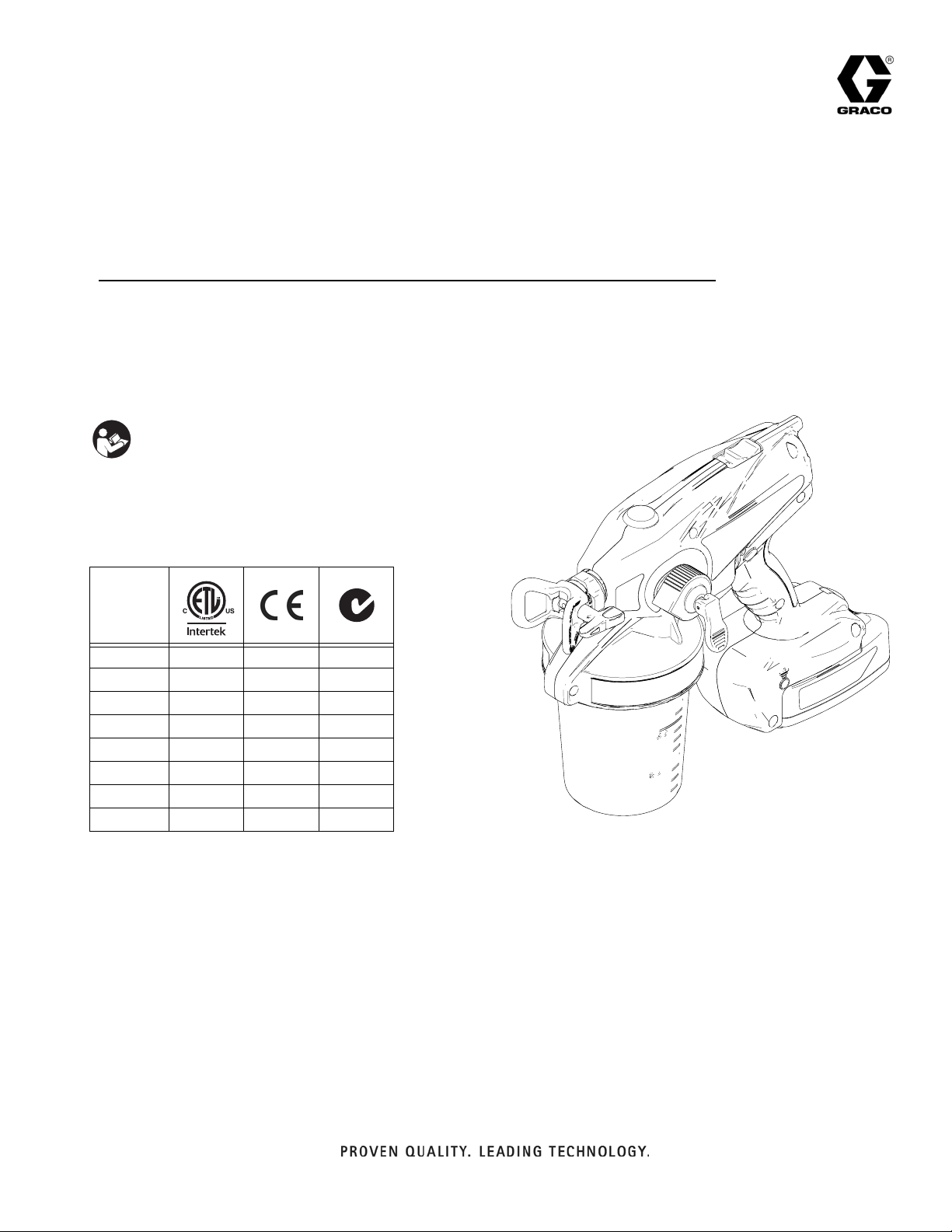
Operation
Fine Finish Hand-Held Paint Sprayer
- For portable spray applications of architectural paints and coatings only
- Not approved for use in explosive atmosphere locations -
- Service only at Graco approved service centers -
- For professional use only -
IMPORTANT SAFETY INSTRUCTIONS
Read all warnings and instructions in this
manual. Save these instructions.
All Models:
Maximum Working Pressure 1700 psi (117 bar, 11.7 MPa)
Model
16F887 ✓
16H240 ✓
16H241 ✓✓
16H242 ✓✓
16H243 ✓
262612 ✓
16H245 ✓
16H829 ✓
3A1698F
EN
-
ti16695a
Page 2

Table of Contents
Table of Contents
Warnings . . . . . . . . . . . . . . . . . . . . . . . . . . . . . . . . . . . . . . 3
Grounding Instructions . . . . . . . . . . . . . . . . . . . . . . . . . 3
Component Identification . . . . . . . . . . . . . . . . . . . . . . . . . 7
Charging the Battery . . . . . . . . . . . . . . . . . . . . . . . . . . . . . 8
Charger Status Indicator Lights . . . . . . . . . . . . . . . . . . 8
Sprayer Status Indicator . . . . . . . . . . . . . . . . . . . . . . . . 8
Common Procedures . . . . . . . . . . . . . . . . . . . . . . . . . . . . 9
Trigger Lock . . . . . . . . . . . . . . . . . . . . . . . . . . . . . . . . . 9
Prime/Pressure Relief Valve Position . . . . . . . . . . . . . . 9
Pressure Relief Procedure . . . . . . . . . . . . . . . . . . . . . . 9
Spray Tip Position . . . . . . . . . . . . . . . . . . . . . . . . . . . . 9
Setting Hi/Lo Switch (Motor Speed) . . . . . . . . . . . . . . 10
Adjusting Pressure . . . . . . . . . . . . . . . . . . . . . . . . . . . 10
Setup . . . . . . . . . . . . . . . . . . . . . . . . . . . . . . . . . . . . . . . . 11
Flexible Suction Tube . . . . . . . . . . . . . . . . . . . . . . . . . 11
Sprayer Setup . . . . . . . . . . . . . . . . . . . . . . . . . . . . . . 12
Starting a New Job (or Refilling the Cup) . . . . . . . . . . . 13
Reversible Tip Selection Chart . . . . . . . . . . . . . . . . . . . . 13
Install Tip/Guard Assembly (if not installed) . . . . . . . . 14
Getting Started with Basic Techniques . . . . . . . . . . . . . 14
Triggering Sprayer . . . . . . . . . . . . . . . . . . . . . . . . . . . 14
Aiming Sprayer . . . . . . . . . . . . . . . . . . . . . . . . . . . . . . 14
Unclogging Spray Tip/Guard Assembly . . . . . . . . . . . . 15
Shutdown and Cleaning . . . . . . . . . . . . . . . . . . . . . . . . . 16
Flushing Sprayer . . . . . . . . . . . . . . . . . . . . . . . . . . . . 16
Cleaning Sprayer Exterior . . . . . . . . . . . . . . . . . . . . . 18
Fine Finish Tip Wear . . . . . . . . . . . . . . . . . . . . . . . . . 18
Storage . . . . . . . . . . . . . . . . . . . . . . . . . . . . . . . . . . . . . . . 18
Replacement Parts and Kits . . . . . . . . . . . . . . . . . . . . . . 19
Parts List . . . . . . . . . . . . . . . . . . . . . . . . . . . . . . . . . . 20
Alternate Priming Method . . . . . . . . . . . . . . . . . . . . . . . . 23
Inlet Valve Removal/Service . . . . . . . . . . . . . . . . . . . . . . 24
Outlet Valve Repair . . . . . . . . . . . . . . . . . . . . . . . . . . . . . 25
Troubleshooting . . . . . . . . . . . . . . . . . . . . . . . . . . . . . . . 26
Technical Data . . . . . . . . . . . . . . . . . . . . . . . . . . . . . . . . . 29
Preferred Material Settings Log . . . . . . . . . . . . . . . . . . . 30
Notes . . . . . . . . . . . . . . . . . . . . . . . . . . . . . . . . . . . . . . . . 31
Graco Standard Warranty . . . . . . . . . . . . . . . . . . . . . . . . 32
Important User Information
Before using your sprayer read this Operation Manual for complete instructions on proper use and safety warnings.
DO NOT RETURN THIS SPRAYER TO THE STORE!
If you experience problems, contact Graco Customer Service at www.graco.com.
Congratulations! You have purchased a high-quality paint sprayer made by Graco Inc. This sprayer is designed to provide
superior spray performance with all architectural paints and coatings. This user information is intended to help you
understand the types of materials that can be used with your sprayer.
Before using this equipment, be sure to read and follow the information on your container label and ask for a Material Safety
Data Sheet (MSDS) from your supplier. The container label and MSDS will explain the contents of the material and the
specific precautions related to it.
Paints, coatings and clean-up materials generally fit into one of the following 3 basic categories:
WATER-BASED:
Your sprayer is compatible with this type of material. Your sprayer is NOT compatible with harsh cleaners such as
chlorine bleach.
OIL-BASED:
mineral spirits or paint thinner. The MSDS must indicate that the flash point of the material is above 100° F. Your
sprayer is compatible with this type of material. Use oil-based material outdoors or in a well-ventilated indoor area
with a flow of fresh air. See the safety warnings in this manual.
FLAMMABLE:
thinner, acetone, denatured alcohol, and turpentine. The container label should indicate that this material is FLAMMABLE. Your sprayer is compatible with this type of material. Use flammable materials outdoors or in a well-ventilated indoor area with a flow of fresh air. See the safety warnings in this manual.
The container label should indicate that the material can be cleaned up with soap and water.
The container label should indicate that the material is combustible and can be cleaned up with
This type of material contains flammable solvents such as xylene, toluene, naphtha, MEK, lacquer
2 3A1698F
Page 3
Warnings
Warnings
The following warnings are for the setup, use, maintenance, and repair of this equipment. The exclamation point
symbol alerts you to a general warning and the hazard symbols refer to procedure-specific risks. When these symbols appear in the body of this manual or on warning labels, refer back to these Warnings. Product-specific hazard
symbols and warnings not covered in this section may appear throughout the body of this manual where applicable.
WARNING
FIRE AND EXPLOSION HAZARD (GROUNDING)
Some oil-based and flammable materials generate static electricity when sprayed. Static electricity creates
an explosion and fire risk. Your sprayer has a grounding cord that will conduct the static electricity to a
grounded electrical outlet. The sprayer and all objects in spray area shall be properly grounded to protect
against static discharge, sparks or shocks.
• Connect the grounding cord when spraying flammable or static producing oil-based materials.
• If there is static sparking or if you feel a shock, stop spraying immediately and connect the sprayer to a
properly grounded electrical outlet with the ground wire provided.
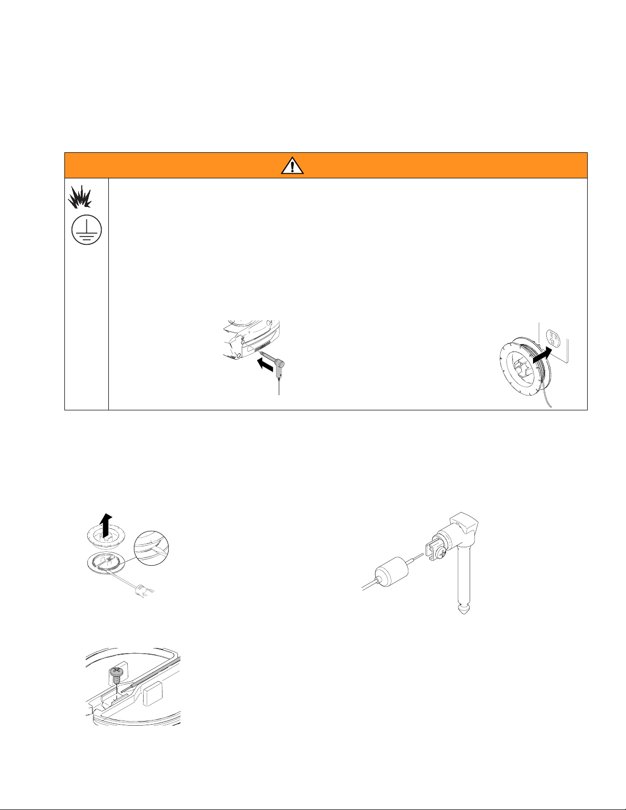
GROUNDING INSTRUCTIONS
Move the sprayer away
from the spray area to a
non-hazardous location.
Plug the ground wire
into the sprayer.
Unwind the ground wire from the spool
and plug it into a properly grounded
electrical outlet.
If the ground wire is not long enough to
reach a grounded electrical outlet, a
3-wire grounded extension cord may be
used to reach a grounded outlet.
Grounding Wire Repair
If the grounding wire breaks at the spool end,
perform the following steps:
1. Unwind wire from grounding spool and use a flat
screwdriver to pry apart the grounding spool.
ti17082a
2. Loosen screw on terminal and remove broken wire.
Strip insulation from grounding wire, insert into terminal and tighten screw.
ti17080a
If the grounding wire breaks at the grounding plug,
perform the following steps:
1. Pull rubber boot off of wire at grounding plug and
slide boot over grounding wire.
ti17081a
2. Loosen screw and remove broken wire. Insert
stripped grounding wire and tighten screw.
3. Replace rubber boot onto grounding plug.
3. Snap the grounding spool back together.
3A1698F 3
Page 4
Warnings
WARNING
WARNINGWARNINGWARNING
FIRE AND EXPLOSION HAZARD
Flammable fumes, such as solvent and paint fumes, in work area can ignite or explode. To help prevent
fire and explosion:
• Do not spray flammable or combustible liquids in a confined area.
• Keep spray area well-ventilated. Keep a good supply of fresh air moving through the area.
• Paint or solvent flowing through the sprayer is able to result in static electricity. Static electricity creates a risk of fire or explosion in the presence of paint or solvent fumes. The sprayer and all objects
in spray area shall be properly grounded to protect against static discharge, sparks, or shocks.
• Always connect the grounding cord provided when spraying flammable materials or static producing
oil-based materials. See Grounding Instructions, page 3.
• If there is static sparking or you feel a shock, stop operation immediately and connect sprayer to a
properly grounded electrical outlet with the ground wire provided.
• Do not spray flammable or combustible materials near open flame or sources of ignition such as cigarettes, external motors, and electrical equipment.
• Do not operate light switches, engines, or similar spark producing products in the spray area.
• Do not smoke in the spray area.
• Keep spray area clean and free of paint or solvent containers, rags, and other flammable materials.
• Know the contents of the paints and solvents being sprayed. Read all Material Safety Data Sheets
(MSDS) and container labels provided with the paints and solvents. Follow the paint and solvents
manufacturer’s safety instructions.
• Fire extinguisher equipment shall be present and working.
SKIN INJECTION HAZARD
High-pressure spray is able to inject toxins into the body and cause serious bodily injury. In the event that
injection occurs, get immediate surgical treatment.
• Do not aim the sprayer at, or spray any person or animal.
• Keep hands and other body parts away from the discharge. For example, do not try to stop leaks with
any part of the body.
• Always engage the trigger lock when not spraying. Verify the trigger lock is functioning properly.
• Always use the spray tip guard. Do not spray without spray tip guard in place.
• Use caution when cleaning and changing spray tips. In the case where the spray tip clogs while
spraying, follow the Pressure Relief Procedure for relieving the pressure before reversing or removing the spray tip to clean.
• Do not leave the unit energized or under pressure while unattended. When the unit is not in use, follow the Pressure Relief Procedure and engage the trigger lock.
• Check parts for signs of damage. Replace any damaged parts with genuine Graco parts.
• This system is capable of producing 1700 psi. Use replacement parts or accessories that are rated a
minimum of 1700 psi.
• Do not carry the sprayer with a finger on the trigger.
• Verify that all connections are secure before operating the unit.
• Know how to stop the unit and bleed pressure quickly. Be thoroughly familiar with the controls.
4 3A1698F
Page 5
Warnings
WARNING
WARNINGWARNINGWARNING
EQUIPMENT MISUSE HAZARD
Misuse can cause death or serious injury.
• Disconnect the battery before servicing.
• Always wear appropriate gloves, eye protection, and a respirator or mask when painting.
• Do not operate or spray near children. Keep children away from equipment at all times.
• Do not overreach or stand on an unstable support. Keep effective footing and balance at all times.
• Stay alert and watch what you are doing.
• Do not operate the unit when fatigued or under the influence of drugs or alcohol.
• Use only in dry locations. Do not expose to water or rain.
• Use in well-lit areas.
• Always replace cracked, broken or missing parts immediately with genuine Graco parts. See Parts
List, page 19.
BATTERY HAZARD
The battery may leak, explode, cause burns, or cause an explosion if mishandled. Contents of an open
battery can cause severe irritation and/or chemical burns. If on skin, wash with soap and water. If in eyes,
flush with water for at least 15 minutes and get immediate medical attention.
• Replace battery only in a well-ventilated area and away from flammable or combustible materials,
including paints and solvents.
• When battery is not in use, keep it away from metal objects like keys, nails, screws or other metal
objects that can short circuit the battery terminals.
• When spraying flammable materials, use only Graco SlimLine battery 16G610. Do not use Graco
premium battery 16D558 when spraying flammable material.
• Do not throw into fire.
• Charge only with Graco approved charger as listed in this manual.
• Do not store at temperatures below 32° or above 113°F (0° to 45°C).
• Do not use at temperatures below 40° or above 90° F (4° to 32°C).
• Do not expose battery to water or rain.
• Do not disassemble, crush, or penetrate the battery.
• Do not use or charge a battery that is cracked or damaged.
• Follow local ordinances and/or regulations for disposal.
CHARGER ELECTRIC SHOCK, FIRE AND EXPLOSION HAZARD
Improper setup or usage can cause electric shock, fire, and explosion.
• Charge only in a well-ventilated area and away from flammable or combustible materials, including
paints and solvents.
• Do not charge on a combustible or flammable surface.
• Do not leave battery unattended while charging.
• Immediately unplug charger and remove battery when charging is complete.
• Charge only Graco approved batteries listed in this manual; other batteries may burst.
• Use only in dry locations. Do not expose to water or rain.
• Do not use a charger that is cracked or damaged.
• If the supply cord is damaged, replace the charger or cord, depending on model.
• Never force the battery into the charger.
• When operating a charger outdoors, always provide a dry location and use an extension cord suitable for outdoor use.
• Disconnect the charger from the outlet before cleaning.
• Ensure that the outside surface of the battery is clean and dry before plugging into the charger.
• Do not attempt to charge non-rechargeable batteries.
• Do not disassemble the charger. Take charger to authorized service center when service or repair is
required.
3A1698F 5
Page 6
Warnings
WARNING
WARNINGWARNINGWARNING
PRESSURIZED ALUMINUM PARTS HAZARD
Use of fluids that are incompatible with aluminum in pressurized equipment can cause serious chemical
reaction and equipment rupture. Failure to follow this warning can result in death, serious injury, or
property damage.
• Do not use 1,1,1-trichloroethane, methylene chloride, other halogenated hydrocarbon solvents or
fluids containing such solvents.
• Many other fluids may contain chemicals that can react with aluminum. Contact your material
supplier for compatibility.
TOXIC FLUID OR FUMES HAZARD
Toxic fluids or fumes can cause serious injury or death if splashed in the eyes or on skin, inhaled, or
swallowed.
• Read MSDS’s to know the specific hazards of the fluids you are using.
• Store hazardous fluid in approved containers, and dispose of it according to applicable guidelines.
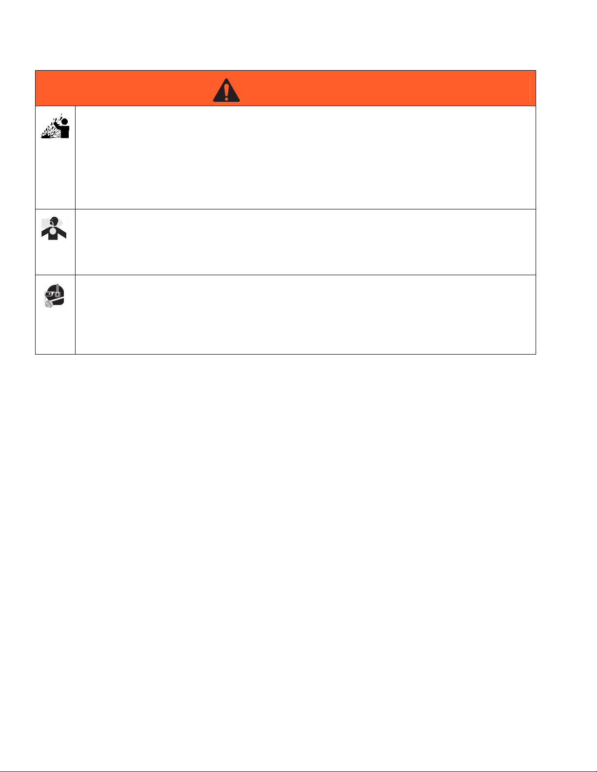
PERSONAL PROTECTIVE EQUIPMENT
You must wear appropriate protective equipment when operating, servicing, or when in the operating
area of the equipment to help protect you from serious injury, including eye injury, hearing loss,
inhalation of toxic fumes, and burns. This equipment includes but is not limited to:
• Protective eyewear, and hearing protection.
• Respirators, protective clothing, and gloves as recommended by the fluid and solvent manufacturer.
6 3A1698F
Page 7
Component Identification
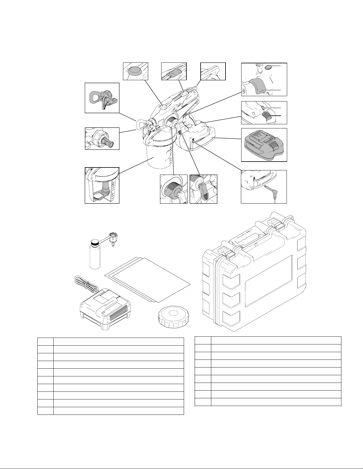
Component Identification
A
*B
C
P
D
N
M
L
K
J
H
G
FE
Q
R
A Fine Finish Tip/Guard Assembly
*B Tip Filter (Reverse Threaded)
C Flexible Suction Tube
D Pressure Control Knob
E Prime/Pressure Relief Valve
F Grounding Plug
G SlimLine Battery
H Battery Release Button
J Indicator Light
K Trigger
W
S
T
L Trigger Lock
MStatic Wick
N Hi/Lo Switch (Motor Speed)
P Outlet Valve Access Plug
Q Startup/Storage Kit
R Lithium Ion Battery Charger
S Cup Liner Replacement (10 Pack)
TCup Lid
WStorage Case
ti16696b
*NOTE: Tip filter is reverse-threaded. Turn left (or counter-clockwise) to tighten, turn right (or clockwise) to loosen.
3A1698F 7
Page 8
Charging the Battery
Charging the Battery
3. When battery becomes fully charged, immediately
unplug the charger from the power supply and remove
the battery from the charger.
Replace and charge battery only in a well-ventilated area
and away from flammable or combustible materials,
including paints and solvents.
Batteries are initially 50% charged to provide optimum battery life and require charging before first use. It takes
approximately 25 minutes to charge a dead battery to 80%,
at which point it can be used. It will take approximately 40
minutes to fully charge a dead battery.
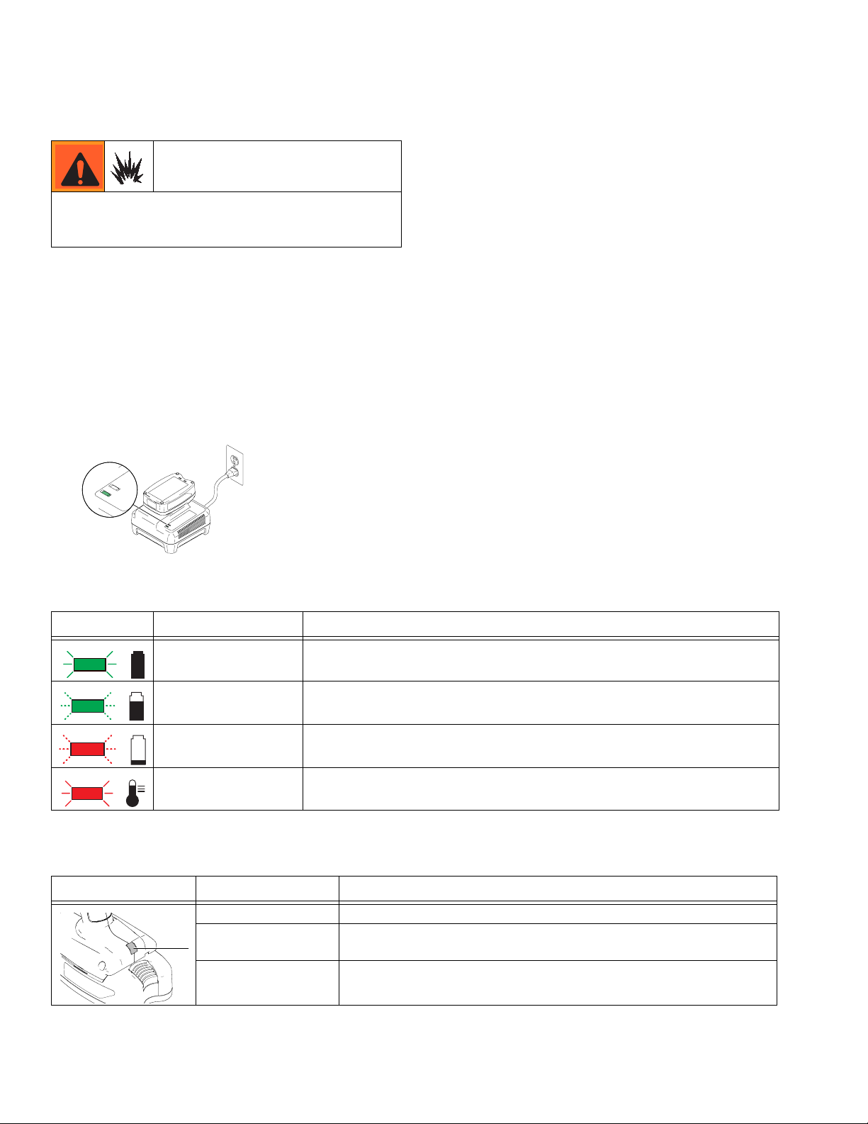
1. Place charger in a dry, well-ventilated area and away
from flammable or combustible materials, including
paints and solvents.
2. Plug charger into an electrical outlet and slide battery
into charger as shown (light will turn on in 5 seconds).
ti14990a
ti16706a
Charger Status Indicator Lights
NOTE: The amount sprayed with each battery varies
depending on material, tip size, motor speed and pressure
setting. Typical results are 1 to 6 cups of material sprayed
per battery. Generally you will get longer battery life at
higher pressure settings and at low motor speed.
Label Appearance Description
Solid green light Indicates a full charge. Battery can be used.
Flashing green light
Flashing red light
Solid red light
Battery is charging, indicates 80% charge.
Battery can be used.
Battery is charging, indicates less than 80% charge.
Do NOT use battery.
Battery is too hot or too cold to charge. Remove battery and allow to cool or
warm up before charging.
Sprayer Status Indicator
Light* Appearance Description
ti16707a
*NOTE: The sprayer status indicator light is visible for 10 seconds after the trigger is released.
No light Normal operation.
Solid red Battery is low on power and needs to be charged, or battery is too cold
and must warm up before spraying.
Flashing red Battery temperature is too high, or tip is clogged.
See Troubleshooting, page 26.
8 3A1698F
Page 9
Common Procedures
Common Procedures
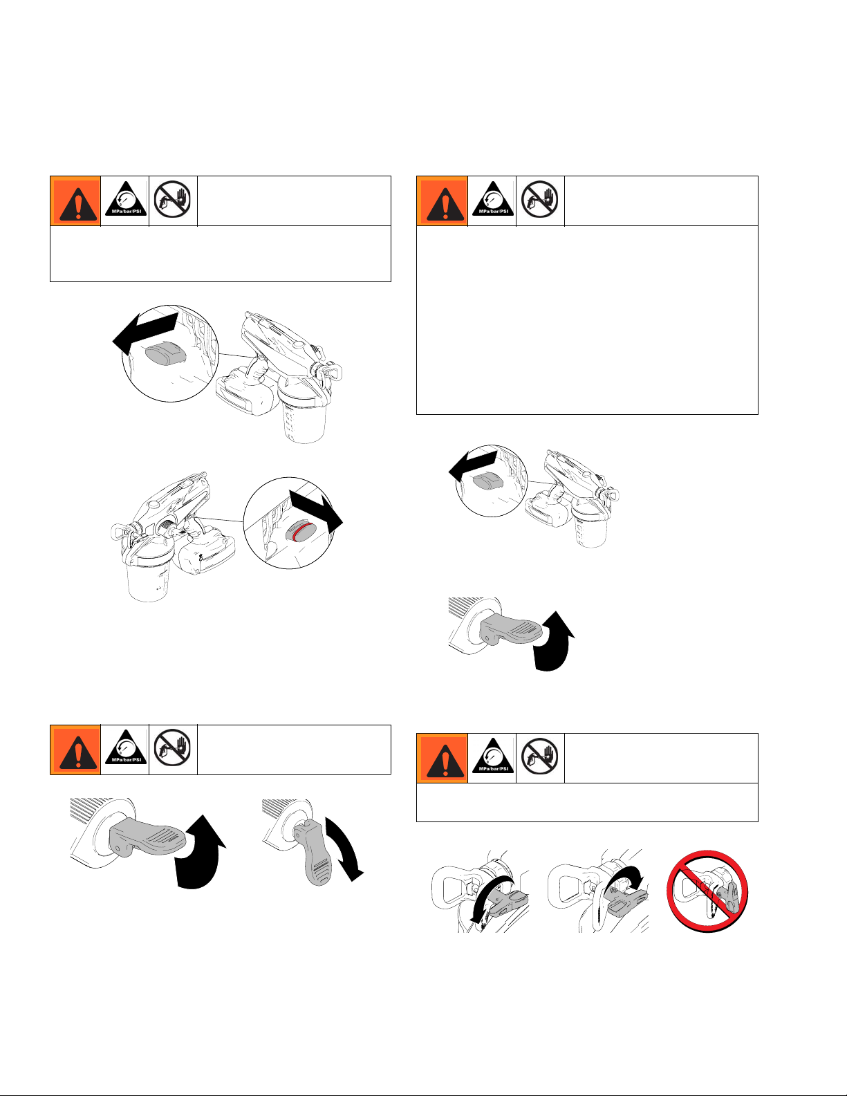
Trigger Lock
Always engage the trigger lock when you stop spraying
to prevent the sprayer from being triggered accidentally
by hand, or if dropped or bumped.
ti14994a
Trigger Locked
ti14995a
ti16699a
Pressure Relief Procedure
Do not operate or spray near children. Do not aim the
sprayer at, or spray any person or animal. Keep hands
and other body parts away from the front of the
sprayer. For example, do not try to stop the paint flow
with any part of the body.
This sprayer builds up an internal pressure of 1,700 psi
during use. Follow this Pressure Relief Procedure
whenever you stop spraying and before cleaning,
checking, servicing, or transporting equipment to
prevent serious injury.
4. Engage trigger lock.
ti16699a
ti16698a
Trigger Unlocked
(red ring is visible)
Prime/Pressure Relief Valve Position
ti16700a
ti14999a
(For priming and releasing
UP position
pump pressure)
ti16701a
DOWN position
(Ready to spray)
5. Put prime/pressure relief valve UP to release pressure.
ti14999a
ti16700a
Spray Tip Position
Always perform Pressure Relief Procedure before
adjusting spray tip position.
ti16992a
ti14985a
Tip Forward
(SPRAY position)
ti14991a
ti14991a
Tip Reversed
(UNCLOG position)
ti15510a
ti15510a
3A1698F 9
Page 10
Common Procedures
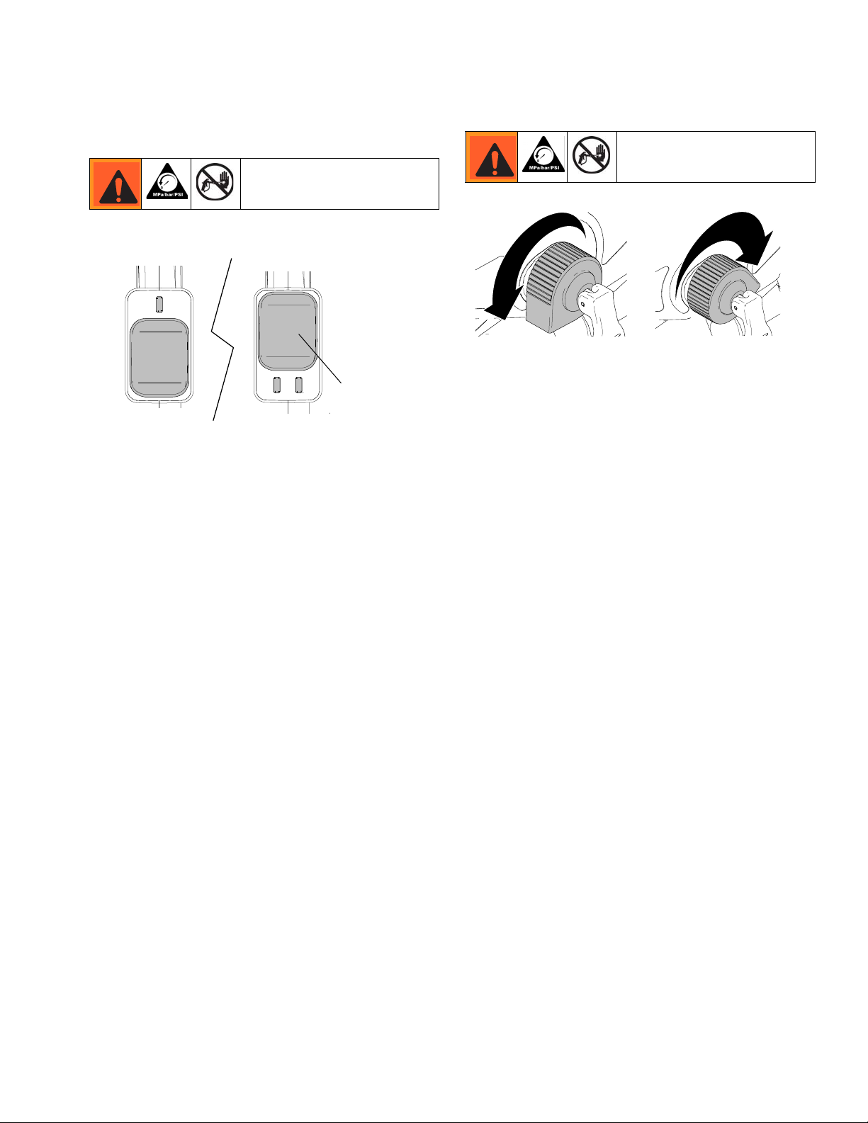
Setting Hi/Lo Switch (Motor Speed)
Low Speed
ti16731a
1. To extend battery life, try spraying with low motor
speed to get an acceptable spray pattern.
2. Shift to high speed if needed to achieve an acceptable spray pattern.
High Speed
Speed Control
Switch
Adjusting Pressure
ti16705a
Minimum Pressure Setting
1. To reduce overspray, always spray at lowest pressure that results in an acceptable spray pattern.
2. Spray test pattern and adjust pressure to get
desired coverage.
3. With some materials, if pressure is set too low, no
material may spray out. Turn pressure control up.
ti16704a
Maximum Pressure Setting
10 3A1698F
Page 11

Setup
Setup
Flammable fumes (such as solvent and paint fumes) in
work area can ignite or explode.
See Grounding Instructions, page 3.
Do not spray flammable or combustible liquids in a confined area.
Keep spray area well-ventilated. Keep a good supply
of fresh air moving through the area.
NOTICE
Your sprayer is NOT compatible with harsh cleaners
such as chlorine bleach. Using these cleaners will
cause damage to the sprayer.
NOTICE
Do NOT shake materials to be used with this
sprayer. Some fine finish lacquers and enamels trap
air when shaken, which can affect sprayer
performance. Stir the material or check the
manufacturer’s recommendation for the material
being sprayed.
Spraying Floors and Base Boards
When spraying floors, rotate the suction tube collar to
the back of the material cup.
ti16709a
NOTE: If the sprayer is angled or tilted too far, the suction tube will lose contact with the material and the
sprayer will stop spraying.
Flexible Suction Tube
This sprayer comes with a suction tube that can be
adjusted for multi-directional spraying.
Spraying Ceilings, Walls and Crown
Molding
When spraying ceilings or walls, rotate the suction tube
collar to the front of the material cup.
ti16710a
ti16711a
3A1698F 11
Page 12

Sprayer Setup
Setup
This sprayer arrives from the factory with a small
amount of test material in the system. It is important
that you flush this material from the sprayer before
using it for the first time:
1. Fill material cup with water or compatible solvent,
thread onto sprayer and hand tighten.
ti14992a
ti16712a
2. Put prime/pressure relief valve to UP position, then
hold trigger in for 10 seconds.
ti16700a
ti14999a
5. Engage trigger lock and put prime/pressure relief
valve UP to release pressure.
ti14994a
ti16699a
ti14999a
ti16700a
6. Unscrew and remove material cup.
7. Disengage trigger lock, put prime/pressure relief
valve DOWN, hold sprayer slightly above material
cup, and pull trigger to discharge fluid from pump.
ti15478a
3. Put prime/pressure relief valve DOWN to spray
position.
ti16701a
ti15425a
4. Reverse spray tip to UNCLOG position and trigger
sprayer into a waste area for 10 seconds.
ti14991a
ti16713a
ti16714a
8. Put prime/pressure relief valve UP and pull trigger to
finish material flushing.
9. Discard material in cup.
12 3A1698F
Page 13

Starting a New Job (or Refilling the Cup)
Starting a New Job
(or Refilling the Cup)
When spraying flammable or combustible materials:
• Remove entire sprayer from hazardous location
when refilling.
• Always ground the material cup when refilling.
• Keep material containers covered between cup
refills.
1. Engage trigger lock and put prime/pressure relief valve
UP to release pressure.
ti16699a
ti14994a
ti16700a
ti14999a
4. Reverse spray tip to UNCLOG position and spray
into waste area for five seconds.
ti14991a
ti14991a
ti15491a
ti14985a
ti16713a
5. Put prime/pressure relief valve UP to release pressure. Then rotate tip back to spray position.
NOTE: Failure to perform this operation could result
in poor spray pattern.
ti16700a
ti16992a
NOTE: If sprayer fails to prime, follow Alternate
Priming Method (page 23).
2. Install material cup liner, fill with material, and
thread onto sprayer.
ti15474a
ti16715a
3. To prime pump, disengage trigger lock and trigger
sprayer for 10 seconds. Then release trigger and
put prime/relief valve DOWN to spray position.
ti16698a
ti14995a
ti15418a
ti16716a
ti15425a
ti16701a
Reversible Tip Selection Chart
Fine Finish Materials and Tip Sizes
Fan
Width
4 in.
(10 cm)
6 in.
(15 cm)
8 in.
(20 cm)
Use with all fine finish materials including “hot” solvents.
THIN
Stains
208 210
308 310 312
MEDIUM
Lacquers, Clears
410 412
HEAVY
Enamels
3A1698F 13
Page 14

Install Tip/Guard Assembly (if not installed)
Install Tip/Guard Assembly
(if not installed)
NOTE: Only use Graco Fine Finish Tip/Guard assemblies.
1. Engage trigger lock and put prime/pressure relief valve
UP to release pressure.
ti16699a
2. Install filter to Spray Tip/Guard Assembly. NOTE: Filter
assembly is reverse-threaded. Turn left (or coun-
ter-clockwise) to install. Turn right (or clockwise) to
remove.
ti16700a
Getting Started with Basic Techniques
Use a piece of scrap cardboard to practice these basic
spraying techniques before you begin spraying the surface.
• Hold sprayer 10 in. (25 cm) from surface and aim
straight at surface. Tilting sprayer to direct spray angle
causes an uneven finish.
(25 cm)
10 in.
even
finish
• Flex wrist to keep sprayer pointed straight. Fanning
sprayer to direct spray at angle causes uneven
finish.
even finish thin thick thin
thick
thin
uneven
finish
ti14780a
ti16712a
ti14775a
NOTICE
Make sure filter is completely screwed into the Tip/Guard
Assembly to avoid damage to the filter. Do not use a
damaged filter or poor sprayer performance may result.
3.
Screw Tip/Guard Assembly onto sprayer. Tighten
retaining nut until completely engaged with sprayer. Do
not overtighten nut.
ti16717a
NOTICE
The tip is a permanently attached to the Tip/Guard
Assembly. Removal will result in damage.
ti16718a
ti16720a
NOTE: How fast you move the sprayer will affect spray
application. If material is pulsating, you are moving too fast.
If material drips, you are moving too slow. See Trouble-
shooting, page 26.
Triggering Sprayer
Pull trigger after starting stroke. Release trigger before end
of stroke. Sprayer must be moving when trigger is pulled
and released.
ti14988a
ti16719a
Start Moving
Pull Trigger
Release Trigger
Aiming Sprayer
Aim tip of sprayer at bottom edge of previous stroke, overlapping each stroke by half.
ti16949a
ti16722a
14 3A1698F
ti14782a
ti16950a
Page 15

Unclogging Spray Tip/Guard Assembly
Unclogging Spray Tip/Guard
Assembly
Do not operate or spray near children. Do not aim the
sprayer at, or spray any person or animal. Keep hands
and other body parts away from the discharge. For
example, do not try to stop leaks with any part of the
body.
1. To unclog tip obstruction, engage trigger lock and
put prime/pressure relief valve UP to release pressure.
ti16700a
ti16699a
ti14994a
ti14999a
5. Disengage trigger lock, put prime/pressure relief
valve DOWN to spray position, and resume spraying.
ti16698a
ti14995a
ti16701a
ti15425a
6. If tip is still clogged, you may have to repeat steps
1 - 5 and rotate the tip from SPRAY to UNCLOG
several times. Repeat step 1 to release pressure,
remove and clean filter, or replace with new tip
assembly.
ti14989a
ti14989a
2. Reverse spray tip to UNCLOG position.
ti14991a
ti14991a
3. Aim sprayer at waste area, disengage trigger lock,
and put prime/pressure relief valve DOWN to spray
position. Pull trigger to clear clog.
ti16698a
ti14995a
ti16701a
ti15425a
4. Engage trigger lock. Put prime/pressure relief valve
UP to release pressure and rotate spray tip back to
SPRAY position.
NOTE: Filter assembly is reverse-threaded:
Turn left (or counter-clockwise) to install.
Turn right (or clockwise) to remove.
NOTICE
Make sure filter is completely screwed into the Tip/Guard
Assembly to avoid damage to the filter. Do not use a
damaged filter or poor sprayer performance may result.
7. When obstruction is cleared, engage trigger lock
and rotate arrow-shaped handle back to SPRAY
position.
ti16699a
ti14994a
ti16992a
ti14985a
ti14994a
ti16700a
ti14999a
ti16992a
3A1698F 15
Page 16

Shutdown and Cleaning
Shutdown and Cleaning
NOTICE
Failure to properly clean sprayer after each use will
result in hardened materials, damage to the sprayer, and
the warranty will no longer be valid. Do not store solvents
other than mineral spirits in sprayer. Always flush with
Graco pump armor prior to storage.
Flushing Sprayer
Do not spray solvents through the spray tip. Clean the tip
in a bucket of compatible solvent.
Keep spray area well-ventilated. Keep a good supply of
fresh air moving through the area.
NOTICE
Protect the internal parts of this sprayer from water.
Do not submerge the sprayer in cleaning fluid. Openings
in shroud allow cooling of mechanical parts and electronics inside. If water or cleaning fluid gets into these openings, the sprayer could malfunction or become
permanently damaged.
3. Remove and clean sprayer intake tube and screen
with water (or flushing fluid) and a brush every time
you flush the sprayer. Reconnect intake tube.
ti15002a
ti16725a
4. Clean cup if not using a liner, and fill with water or
appropriate flushing fluid.
ti16726a
ti15001a
5. Reconnect material cup and shake sprayer to move
clean water around and clean all areas inside of
cup.
1. Engage trigger lock and pull prime/pressure relief
valve UP to release pressure.
ti16699a
ti16700a
2. Remove material cup and return excess material to
proper container. If used, properly dispose the cup
liner.
ti15000a
ti16724a
ti15441a
ti16723a
6. Disconnect trigger lock and trigger sprayer for
approximately 15 seconds. Engage trigger lock.
ti16993a
ti16716a
7. Discard contaminated fluid and refill with appropriate flushing fluid.
16 3A1698F
Page 17

Shutdown and Cleaning
8. Disengage trigger lock, reverse tip to UNCLOG
position, and pull trigger for 5 seconds to prime
sprayer.
ti14995a
ti16698a
ti14991a
9. Put prime/pressure relief valve DOWN to spray
position. Trigger sprayer into waste area until no
paint appears in water or flushing fluid.
ti16701a
ti15425a
ti15491a
ti16713a
10. If sprayer is not completely clean, repeat steps 4-9.
To avoid serious injury or damage to equipment, do not
expose the sprayer electronics to flushing solvents.
Keep sprayer at least 10 in. above the rim of the con-
tainer when flushing.
11. Engage trigger lock and put prime/pressure relief
valve UP to release pressure.
ti16699a
ti14994a
ti16700a
12. Remove material cup and discard used fluid.
13. Use a stiff wire such as a paper clip to make sure
vent hole is open.
ti17102a
14. Remove Spray Tip/Guard Assembly and clean with
water or flushing fluid. A soft brush can be used to
loosen and remove dried material if needed.
ti16727a
ti15529a
Keep spray area well-ventilated. Keep a good supply
of fresh air moving through the area. When flushing
with solvents, always ground the sprayer and waste
container.
ti15003a
ti15003a
NOTICE
The tip is permanently attached to the guard. Removing
the tip from the guard will result in damage to the tip
assembly.
Do not store tip/guard assembly or suction tube in solvent other than mineral spirits. Damage to parts may
occur.
3A1698F 17
Page 18

Storage
Cleaning Sprayer Exterior
• Wipe paint off outside of sprayer using a soft cloth
moistened with water or flushing fluid.
Do NOT submerge the sprayer.
ti16728a
This sprayer is
equipped with a static
wick that reduces the
build-up of static charge
to reduce the risk of fire
and explosion. KEEP
THIS SURFACE
CLEAN OF OVERSPRAY.
ti16951a
1. Dilute 4 oz. bottle of Pump Armor Concentrate with
an additional 4 oz. of water in material cup.
4 oz
ti16729a
2. Thread cup into sprayer, put prime/pressure relief
valve to UP position and squeeze sprayer trigger for
approximately 10 seconds.
ti16700a
ti16716a
3. Reverse spray tip to UNCLOG position, put
prime/pressure relief valve DOWN to spray position,
and aim sprayer into waste area. Pull trigger for 1-2
seconds.
ti14991a
ti14991a
ti15425a
ti16701a
ti16716a
ti15418a
Fine Finish Tip Wear
• Fine Finish Tip/Guard assembly may require
replacement depending on abrasiveness of paint.
• Do not spray with worn tip. See Troubleshooting,
page 26.
Storage
NOTICE
Failure to store sprayer with Pump Armor will result in
operational problems the next time you spray. Always
circulate Pump Armor through the sprayer after cleaning. Water or solvents other than mineral spirits
left in the sprayer will corrode and damage the
pump.
4. Properly dispose of used Pump Armor mixture from
material cup and rinse cup with water.
ti16726a
5. Recharge battery to full charge before storage. See
Charging the Battery, page 8.
6. Store sprayer indoors in a cool, dry place. Store in
an upright position only. Never store sprayer with
material in the cup.
ti16730a
18 3A1698F
Page 19

Replacement Parts and Kits
Replacement Parts and Kits
70
31 69
32
24
68
51
20
73
31
64
65
35
60
40
39
43
45
44
42
31
26
10
9
7
8
6
74
5
12
14
15
16
56
25
11
13
1717
28
27
46
30
29
63
31
62
66
67
34
37
33
36
32
41
38
59
53
20
1
2
8 16
2121
23
57
4
3
61
ti20355a
3A1698F 19
Page 20

Parts List
Replacement Parts and Kits
If you have this model sprayer
Ref.
(model number is the same as the part number,
Models 16F887, 16H829 24J421 Bare Sprayer (no tip, battery, suction tube, or material cup)
Model 16H240 24J435 Bare Sprayer (no tip, battery, suction tube, or material cup)
Models 16H243, 262612 24J555 Bare Sprayer (no tip, battery, suction tube, or material cup)
Models 16H241, 16H242 24J581 Bare Sprayer (no tip, battery, suction tube, or material cup)
1 All Models 243103 Pump Armor (32oz)
2 Non-Euro Models 16F887, 16H240, 16H242 16M816 Startup/Storage Kit
Euro Models 16H241, 16H829, 16H243, 262612,
16H245
3 All Models 24J422 Storage Case
4 100-120V Models 16F887, 16H240, 16H242 16D559 Lithium Ion Battery Charger
230V Models 16H241, 16H829, 16H243, 262612,
16H245
5 All Models FNS208 208 Fine Finish Spray Tips/Guard Assembly
All Models FNS308 308 Fine Finish Spray Tips/Guard Assembly
All Models FNS210 210 Fine Finish Spray Tips/Guard Assembly
All Models FNS310 310 Fine Finish Spray Tips/Guard Assembly
All Models FNS410 410 Fine Finish Spray Tips/Guard Assembly
All Models FNS312 312 Fine Finish Spray Tips/Guard Assembly
All Models FNS412 412 Fine Finish Spray Tips/Guard Assembly
6 All Models 24E376 Tip Filter Kit, 1-pack, 60 mesh
All Models 24F039 Tip Filter Kit, 3-pack, 60 mesh
All Models 24F640 Tip Filter Kit, 1-pack, 100 mesh
All Models 24F641 Tip Filter Kit, 1-pack, 60 mesh
7 All Models 16H933 Packing, O-Ring (included in 8)
8 All Models 24J433 Kit, repair, needle assembly (includes 7 and wrench)
9 All Models 115478 Screw (included in 30)
10 All Models 16U235 Complete Pump Assembly (includes 11-17, 24-28, 44, 62, 63, 65, 66,
All Models 16U237 Pump Housing only (includes 26, 27, 44, 62, 63, 65, 66, 68-70)
11 All Models 24J424 Inlet Valve Repair Kit (includes 11, 12, 13) (included in 16)
12 All Models 24J424 Inlet Valve Repair Kit (includes 11, 12, 13) (included in 16)
13 All Models 24J424 Inlet Valve Repair Kit (includes 11, 12, 13) (included in 16)
14 All Models 124582 O-Ring (included in 16)
15 All Models 119790 O-Ring (included in 16)
16 All Models 16H641 Pump Valve Repair Kit (includes 11-17, 24 and wrench)
17 All Models 16H934 O-Ring (included in 16, 21)
20 All Models 16J731 Seal, Reservoir (included in 23, 51)
21 All Models 24J423 Tube, suction with strainer inlet (includes 17)
23 All Models 16H618 Material Cup with cover and seal (includes 51)
24 All Models 16H641 Pump Valve Repair Kit (includes 11-17, 24 and wrench)
25 All Models 16H119 Kit, repair, prime / pressure relief valve (includes 43-45)
26 All Models 16U235 Complete Pump Assembly (includes 11-17, 24-28, 44, 62, 63, 65, 66,
All Models 16U237 Pump Housing only (includes 26, 27, 44, 62, 63, 65, 66, 68-70)
27 All Models 16U235 Complete Pump Assembly (includes 11-17, 24-28, 44, 62, 63, 65, 66,
All Models 16U237 Pump Housing only (includes 26, 27, 44, 62, 63, 65, 66, 68-70)
28 All Models 16U236 Kit, reciprocator (includes 38 (qty 10), 44, 62, 63, 65, 66, 68-70)
29 All Models 16G740 Screw (included in 30)
30 All Models 16U239 Kit, repair, drive housing (includes 9, 29, 38 (qty 10), 44, 62, 63,
31 All Models 16U234 Kit, repair, motor, control board (includes 29, 34, 38 (qty 10) 44, 62,
which is below the handle)
Order Part
Number:
16P358 Startup/Storage Kit
16G615 Lithium Ion Battery Charger
68-70)
68-70)
68-70)
65-70)
63, 65-70)
Table continues on the following page.
Description
20 3A1698F
Page 21

Replacement Parts and Kits
Ref.
If you have this model sprayer
(model number is the same as the part number,
32 Models 16F887, 16H241, 16H242, 16H829 16U240 Enclosure replacement kit (includes 20, 34-37, 38 (qty 10), 39, 44, 56,
Model 16H240 16U241 Enclosure replacement kit (includes 20, 34-37, 38 (qty 10), 39, 44, 56,
Models 16H243, 16H245, 262612 16U242 Enclosure replacement kit (includes 20, 34-37, 38 (qty 10), 39, 44, 56,
33 All Models 16U238 Kit, repair, switch (included in 31)
34 Models 16F887, 16H241, 16H242, 16H829 16U240 Enclosure replacement kit (includes 20, 34-37, 38 (qty 10), 39, 44, 56,
Model 16H240 16U241 Enclosure replacement kit (includes 20, 34-37, 38 (qty 10), 39, 44, 56,
Models 16H243, 16H245, 262612 16U242 Enclosure replacement kit (includes 20, 34-37, 38 (qty 10), 39, 44, 56,
35 Models 16F887, 16H241, 16H242, 16H829,
16H240
Models 16H243, 16H245, 262612 16F636 Label, Made in USA
36 All Models 16C936 Plug, Service Hole
37 Models 16F887, 16H241, 16H242, 16H829 16U240 Enclosure replacement kit (includes 20, 34-37, 38 (qty 10), 39, 44, 56,
Model 16H240 16U241 Enclosure replacement kit (includes 20, 34-37, 38 (qty 10), 39, 44, 56,
Models 16H243, 16H245, 262612 16U242 Enclosure replacement kit (includes 20, 34-37, 38 (qty 10), 39, 44, 56,
38 All Models 119236 Screw
39 Models 16F887, 16H241, 16H242, 16H829 16U240 Enclosure replacement kit (includes 20, 34-37, 38 (qty 10), 39, 44, 56,
Model 16H240 16U241 Enclosure replacement kit (includes 20, 34-37, 38 (qty 10), 39, 44, 56,
Models 16H243, 16H245, 262612 16U242 Enclosure replacement kit (includes 20, 34-37, 38 (qty 10), 39, 44, 56,
40 Models 16F887, 16H829 16G644 Label, brand
Model 16H240 16G645 Label, brand
Model 16H241, 16H242 16H831 Label, brand
Model 16H243, 262612 16H816 Label, brand
41 All Models 16G643 Label
42 All Models 16H256 Reel, Ground
43 All Models 16H119 Kit, repair, prime / pressure relief valve (includes 43-45)
44 All Models 16H842 Pin
45 All Models 16H119 Kit, repair, prime / pressure relief valve (includes 43-45)
46 All Models 16G610 Battery
51 All Models 24D425 Kit, lid
53 All Models 16D562 Cup Liner Replacement (10 pack)
56 Models 16F887, 16H241, 16H242, 16H829 16U240 Enclosure replacement kit (includes 20, 34-37, 38 (qty 10), 39, 44, 56,
Model 16H240 16U241 Enclosure replacement kit (includes 20, 34-37, 38 (qty 10), 39, 44, 56,
Models 16H243, 16H245, 262612 16U242 Enclosure replacement kit (includes 20, 34-37, 38 (qty 10), 39, 44, 56,
57
▲
Models 16F887, 16H240 *24J425 Warning Labels Kit ENG/FRE/SPA
Models 16H829 *24J518 Warning Labels Kit SPA/POR/ITA Model 16H829
Models 16H241, 16H242 *24J554 Warning Labels Kit ASIA/ANZ Models 16H241, 16H242
Models 16H243, 262612 24J521 Multi-Language Warning Labels Kit, Body
Models 16H243, 262612 24J519 Multi-Language Warning Labels Kit, Ground Spool
Models 16H243, 262612 24J520 Multi-Language Warning Labels Kit, Charger
Models 16H243, 262612 24J522 Multi-Language Warning Labels Kit, Battery
59
▲
All Models Warning Label (included in 24J425)
60 All Models 16G646 Control Label
which is below the handle)
Order Part
Number:
62-66, 68-70)
62-66, 68-70)
62-66, 68-70)
62-66, 68-70)
62-66, 68-70)
62-66, 68-70)
16E859 Label, Made in USA
62-66, 68-70)
62-66, 68-70)
62-66, 68-70)
62-66, 68-70)
62-66, 68-70)
62-66, 68-70)
62-66, 68-70)
62-66, 68-70)
62-66, 68-70)
*
Contains all warning labels for the models listed
Description
3A1698F 21
Page 22

Replacement Parts and Kits
Ref.
If you have this model sprayer
(model number is the same as the part number,
61 Model 16H241 only 124783 Plug Adapter
62-70 Models 16F887, 16H241, 16H242, 16H829 16U240 Enclosure replacement kit (includes 20, 34-37, 38 (qty 10), 39, 44, 56,
Model 16H240 16U241 Enclosure replacement kit (includes 20, 34-37, 38 (qty 10), 39, 44, 56,
Models 16H243, 16H245, 262612 16U242 Enclosure replacement kit (includes 20, 34-37, 38 (qty 10), 39, 44, 56,
73
▲
All Models Warning Label (included in 24J425)
74 All Models 16H137 O-Ring (included in 5)
▲
Replacement Danger and Warning Labels, Tags and Cards are available at no cost.
which is below the handle)
Order Part
Number:
Description
62-66, 68-70)
62-66, 68-70)
62-66, 68-70)
22 3A1698F
Page 23

Alternate Priming Method
Alternate Priming Method
Move sprayer to a non-hazardous area before servicing.
If sprayer fails to prime, the inlet valve may be stuck due
to paint residue. Perform the steps below.
1. Engage trigger lock and pull prime/pressure relief
valve UP to release pressure.
ti16699a
2. Remove material cup and suction tube.
ti16700a
5. Leaving the sprayer upside-down, disengage trigger
lock and quickly trigger sprayer until material comes
out of drain port.
ti16698a
ti16997a
6. Install strainer on suction tube and thread material
cup back onto sprayer.
ti14992a
ti15500a
ti16712a
7. Trigger gun for 10 seconds then release trigger and
put prime/pressure relief valve DOWN to spray position.
ti16746a
3. Use a pencil or thin rod to lightly push on inlet valve
to make sure it moves up and down freely.
ti15509a
ti16753a
ti15505a
4. If inlet valve does not move freely, perform Inlet
Valve Removal, page 24. If inlet valve moves
freely, install suction tube without strainer, turn
sprayer upside-down, and slowly pour flushing
material into suction tube until full.
ti15509a
ti16716a
ti16701a
8. Reverse spray tip to UNCLOG position and spray
into waste area for five seconds to ensure sprayer
has primed.
ti14991a
ti16713a
9. Pull prime/pressure relief valve up to release pressure, reverse spray tip to SPRAY position and put
prime/pressure relief valve DOWN to spray position.
Sprayer is now ready to spray. Perform Starting
New Job procedure, page 13.
ti16996a
3A1698F 23
Page 24

Inlet Valve Removal/Service
Inlet Valve Removal/Service
Move sprayer to a non-hazardous area before servicing.
1. Engage trigger lock and pull prime/pressure relief
valve UP to release pressure.
ti16699a
2. Remove material cup, suction tube, and battery.
ti16746a
ti16700a
Installation
NOTE: Before installing, make sure o-ring (c) is installed
on inlet valve (b).
1. Place inlet valve (b) with spring (a) on top of inlet fitting (d). Push inlet fitting up into pump cavity.
a
b
c
d
ti16744a
2. Hold inlet in place and turn sprayer upside-down.
Remove inlet fitting and visually check to see that
inlet valve has seated correctly.
ti15502a
ti16745a
3. Hold sprayer upside-down and use wrench or
socket to loosen and remove inlet fitting, inlet valve,
and spring.
ti16747a
NOTE: Make sure the spring also comes out. Use
needle-nose pliers to remove if needed. Inlet cavity
should be completely empty (as shown below).
4. Clean as much excess material from inlet cavity as
possible. Make sure you also clean spring (a), inlet
valve (b), o-ring (c), and top of inlet fitting (d).
ti16743a
ti15500a
3. Replace inlet fitting and use wrench or socket to
tighten to 10 ft-lb.
NOTICE
Do NOT over-tighten inlet fitting. Damage to the
equipment will occur.
4. Use a pencil or thin rod to lightly push on inlet valve
to make sure it moves up and down freely. Perform
Starting New Job procedure, page 13.
ti15509a
ti17099a
ti16753a
5. Use a thin wire to check that the outlet valve moves
freely. If valve does not move freely, perform Outlet
Valve Repair, page 25.
24 3A1698F
Page 25

Outlet Valve Repair
Outlet Valve Repair
Move sprayer to a non-hazardous area before servicing.
NOTE: Before doing any repair to pump, perform
Flushing Sprayer procedure, page 16.
Removal
1. Engage trigger lock and pull prime/pressure relief
valve UP to release pressure.
ti16699a ti16700a
2. Remove battery.
4. Use tool (supplied) to loosen and remove outlet
valve fitting. Make sure old o-ring, seat, outlet valve,
and spring are out of pump outlet cavity.
ti15506a
ti16748a
Installation
1. Screw outlet valve fitting into threads. Use tool
(supplied) and tighten to 8 ft-lb.
3. Remove pump outlet cap.
ti14996a
ti15503a
ti16745a
ti16749a
ti15508a
ti16750a
2. Press pump outlet cap into place.
ti15507a
ti16751a
Outlet cap prevents the discharge of static electricity.
Always replace outlet cap after installing outlet valve.
3A1698F 25
Page 26

Troubleshooting
Problem Cause Solution
Sprayer makes no sound when
trigger is pulled
Sprayer makes sound but no material is
sprayed when trigger is pulled
Troubleshooting
Check everything in this Troubleshooting Table before
you bring the sprayer to an authorized service center.
Trigger is locked. Disengage trigger lock. See page 9.
Status Indicator Light is solid RED when
triggering, indicating that the battery
charge is low, or the battery is too cold.
Status Indicator Light is flashing RED
when triggering, indicating that the battery is too hot to operate.
Status Indicator Light does not light when
sprayer is triggered. Battery is not
installed or is damaged.
Sprayer is not primed. Prime the pump. See Starting a new Job
Prime/relief valve is in UP position. Put valve DOWN to spray position.
Suction Tube is missing or improperly
installed.
Suction Tube screen or vent hole is
clogged.
Suction Tube o-rings are damaged or
missing.
Tip is not in SPRAY position. Turn tip to SPRAY position.
Tip is clogged. See Unclogging Tip/Guard
Tip filter is clogged. Remove and clean tip filter. See Unclog-
Pressure control is too low or Hi/Lo switch
is in Lo range.
Sprayer has been tilted too far and suction tube has lost contact with material.
No or low material in cup. Refill cup with material and prime the
Inlet valve is stuck from material
residue left in sprayer.
Pump is clogged, frozen, or has debris
inside.
Material is leaking from hole in front of
sprayer.
Replace with charged battery and place
old battery in charger, or allow battery to
warm up.
Allow battery to cool.
Install battery or replace.
(or Refilling the Cup), page 13. If
sprayer fails to prime, follow Alternate
Priming Method (page 23).
Make sure Suction Tube is properly
installed.
See Shutdown and Cleaning, page 16.
Replace Suction Tube o-rings.
Assembly, page 15.
ging Tip/Guard Assembly, page 15.
Turn pressure control up or shift Hi/Lo
switch to Hi range.
Make sure cup is filled with material.
Rotate suction tube, page 11. Do not tilt
the cup too far. Prime the pump. See
Starting a new Job (or Refilling the
Cup), page 13.
pump.
Use a pencil or thin rod to lightly push on
inlet valve to make sure it moves up and
down freely. See Inlet Valve
Removal/Service, page 24.
See Outlet Valve Repair, page 25 and
Inlet Valve Removal/Service, page 24.
Sprayer has reached maximum life.
Replace sprayer.
26 3A1698F
Page 27

Troubleshooting
Problem Cause Solution
Sprayer sprays with poor results Tip is partially clogged See Unclogging Tip/Guard Assembly,
page 15.
Tip is not in correct position Rotate tip to SPRAY position.
Incorrect tip for application of
material.
Tip filter is partially clogged or damaged. Clean or replace filter. See page 15.
Suction Tube screen is partially clogged. Clean or replace Suction Tube. See page
Tip is worn or damaged Replace tip. See Install Tip/Guard
Material being sprayed is aerated
because it was shaken.
Pressure control is too low or Hi/Lo switch
is in Lo range
Material being sprayed is too cold to
spray.
Inlet or outlet valves are worn. See Outlet Valve Repair, page 25 and
Paint leaks from sprayer trigger area. Sprayer has reached its maximum life. Replace sprayer.
Battery is discharged but charger still displays green light when battery is inserted.
Battery does not last long. Battery life varies with material, tip size,
Damaged battery. Replace battery.
pressure, and speed setting.
See Reversible Tip Selection Chart,
page 13.
16.
Assembly, page 14.
Do NOT shake material. Stir the material
or check the manufacturer’s recommendation for the material being sprayed.
Turn up pressure control or shift Hi/Lo
switch to hi range.
Warm material.
Inlet Valve Removal/Service, page 24.
See Charging the Battery, page 8.
Spray Pattern Diagnostics
Problem Cause Solution
Spray pattern is pulsating:
Spray pattern has tails:
ti15526a
Operator is moving too fast while spraying. Slow speed of movement.
Hi/Lo switch is in Lo range. Shift Hi/Lo switch to Hi range.
Tip or tip filter is clogged. Unclog tip or clean tip filter, page 15.
Pressure control is too low. Turn up pressure control.
Incorrect tip for application of
material.
Material not compatible with sprayer. Switch material.
Inlet or outlet valves are worn. See Outlet Valve Repair, page 25 and Inlet
See Reversible Tip Selection Chart, page
13.
Valve Removal/Service, page 24.
3A1698F 27
Page 28

Problem Cause Solution
Spray pattern has dripping:
Spray pattern is too narrow:
ti15523a
ti15523a
Spray pattern is too wide:
Troubleshooting
Sprayer is moving too slow for material. Move sprayer faster while spraying.
Sprayer is too close to target surface. Move sprayer away from surface 10 in. (25
cm)
Holding trigger while changing spray
Release trigger when changing directions.
direction.
Incorrect tip for application of
material.
Pressure control is too high or Hi/Lo Switch
is in Hi range.
See Reversible Tip Selection Chart, page
13.
Turn down pressure control or shift Hi/Lo
Switch to Lo range.
Tip is worn or damaged. Replace tip. See Install Tip/Guard Assembly,
page 14.
Sprayer is too close to target surface. Move sprayer away from surface 10 in. (25
cm)
Incorrect tip for application of material. See Reversible Tip Selection Chart, page
13.
Tip is worn or damaged. Replace tip. See Install Tip/Guard Assembly,
page 14.
Sprayer is too far away from target surface. Move sprayer closer to surface.
Incorrect tip for application of material. See Reversible Tip Selection Chart, page
13.
ti15527a
ti15527a
Spray pattern “spits” at the
end or beginning:
ti15525a
ti15525a
Tip continues to drip or ooze
material after trigger is
released:
ti15528a
ti15528a
Excess material has accumulated on Spray
See Shutdown and Cleaning, page 16.
Tip/Guard Assembly.
Tip filter is partially clogged or damaged. Clean or replace filter. See page 15.
Tip/Guard Assembly not threaded com-
See Install Tip/Guard Assembly, page 14.
pletely onto sprayer.
Seat is worn. Replace Spray tip.
Sprayer is worn out. Replace sprayer.
Tip filter is partially clogged or damaged. Clean or replace filter. See page 15.
Tip/Guard Assembly not threaded com-
See Install Tip/Guard Assembly, page 14.
pletely onto sprayer.
Seat is worn. Replace Spray tip.
Needle valve is damaged or worn out. Replace needle valve.
28 3A1698F
Page 29

Technical Data
Technical Data
Sprayer:
Adjustable Pressure Range 500 to 1500 psi (34 to 103 bar, 0.34 to 10.3 MPa)
Maximum working pressure 1700 psi (117 bar, 11.7 MPa)
Weight 5.0 lb (2.25 kg)
Dimensions:
Length 13.75 in. (34.9 cm)
Width 5.5 in. (14.0 cm)
Height 9.7 in. (24.6 cm)
Storage temperature range ◆❖ 32° to 113°F (0° to 45°C)
Operating temperature range ✔ 40° to 90° F (4° to 32°C)
Storage Humidity Range 0% to 95% relative humidity, non-condensing
Sound Pressure Level 79.5 dBa† (for sound power level, add 11 dBa)
Vibration Level Acceleration
Charger:
Charging Time 25 minutes to 80%, 40 minutes to 100%
Power Source 120 VAC
Battery:
Voltage 18 VDC, Lithium Ion
Capacity 1.2 Ah, 21.6 Wh
Less than 8.2 feet/s
2
2.5 m/s2††
Pump damage will occur if fluid freezes in pump.
◆
Damage to plastic parts may result if impact occurs in low temperature conditions.
❖
Changes in paint viscosity at very low or very high temperatures can affect sprayer performance.
✔
per ISO 3744 measured at 3.1 feet (1m)
†
per ISO 5349, no load condition
††
3A1698F 29
Page 30

Preferred Material Settings Log
Preferred Material Settings Log
Date
03/24/2011 Crown molding Urethane varnish FF308
EXAMPLE
Item
Sprayed
Material
Sprayed
Spray
Tip
Motor Speed
(Circle One)
Pressure Setting
(Mark Dial)
30 3A1698F
Page 31

Notes
Notes
3A1698F 31
Page 32

Graco Standard Warranty
Graco warrants all equipment referenced in this document which is manufactured by Graco and bearing its name to be free from defects in
material and workmanship on the date of sale to the original purchaser for use. With the exception of any special, extended, or limited warranty
published by Graco, Graco will, for a period of twelve months from the date of sale, repair or replace any part of the equipment determined by
Graco to be defective. This warranty applies only when the equipment is installed, operated and maintained in accordance with Graco’s written
recommendations.
This warranty does not cover, and Graco shall not be liable for general wear and tear, or any malfunction, damage or wear caused by faulty
installation, misapplication, abrasion, corrosion, inadequate or improper maintenance, negligence, accident, tampering, or substitution of
non-Graco component parts. Nor shall Graco be liable for malfunction, damage or wear caused by the incompatibility of Graco equipment with
structures, accessories, equipment or materials not supplied by Graco, or the improper design, manufacture, installation, operation or
maintenance of structures, accessories, equipment or materials not supplied by Graco.
This warranty is conditioned upon the prepaid return of the equipment claimed to be defective to an authorized Graco distributor for verification of
the claimed defect. If the claimed defect is verified, Graco will repair or replace free of charge any defective parts. The equipment will be returned
to the original purchaser transportation prepaid. If inspection of the equipment does not disclose any defect in material or workmanship, repairs
will be made at a reasonable charge, which charges may include the costs of parts, labor, and transportation.
THIS WARRANTY IS EXCLUSIVE, AND IS IN LIEU OF ANY OTHER WARRANTIES, EXPRESS OR IMPLIED, INCLUDING BUT NOT LIMITED
TO WARRANTY OF MERCHANTABILITY OR WARRANTY OF FITNESS FOR A PARTICULAR PURPOSE
Graco’s sole obligation and buyer’s sole remedy for any breach of warranty shall be as set forth above. The buyer agrees that no other remedy
(including, but not limited to, incidental or consequential damages for lost profits, lost sales, injury to person or property, or any other incidental or
consequential loss) shall be available. Any action for breach of warranty must be brought within two (2) years of the date of sale.
GRACO MAKES NO WARRANTY, AND DISCLAIMS ALL IMPLIED WARRANTIES OF MERCHANTABILITY AND FITNESS FOR A
PARTICULAR PURPOSE, IN CONNECTION WITH ACCESSORIES, EQUIPMENT, MATERIALS OR COMPONENTS SOLD BUT NOT
MANUFACTURED BY GRACO
the warranty, if any, of their manufacturer. Graco will provide purchaser with reasonable assistance in making any claim for breach of these
warranties.
In no event will Graco be liable for indirect, incidental, special or consequential damages resulting from Graco supplying equipment hereunder, or
the furnishing, performance, or use of any products or other goods sold hereto, whether due to a breach of contract, breach of warranty, the
negligence of Graco, or otherwise.
FOR GRACO CANADA CUSTOMERS
The Parties acknowledge that they have required that the present document, as well as all documents, notices and legal proceedings entered into,
given or instituted pursuant hereto or relating directly or indirectly hereto, be drawn up in English. Les parties reconnaissent avoir convenu que la
rédaction du présente document sera en Anglais, ainsi que tous documents, avis et procédures judiciaires exécutés, donnés ou intentés, à la suite
de ou en rapport, directement ou indirectement, avec les procédures concernées.
. These items sold, but not manufactured by Graco (such as electric motors, switches, hose, etc.), are subject to
.
Graco Information
For the latest information about Graco products, visit www.graco.com.
TO PLACE AN ORDER, contact your Graco distributor or call to identify the nearest distributor. Phone: 612-623-6926 or Toll Free: 1-800-690-2894 Fax: 612-623-6893 Toll Free Fax: 1-800-334-6955
All written and visual data contained in this document reflects the latest product information available at the time of publication.
GRACO INC. AND SUBSIDIARIES • P.O. BOX 1441 • MINNEAPOLIS MN 55440-1441 • USA
Copyright 2010, Graco Inc. All Graco manufacturing locations are registered to ISO 9001.
Graco reserves the right to make changes at any time without notice.
For patent information, see www.graco.com/patents.
Original instructions.
This manual contains English. MM 3A1698
Graco Headquarters: Minneapolis
International Offices: Belgium, China, Japan, Korea
www.graco.com
Revised January 2013
 Loading...