

Page 1
Instructions-Parts
332459A
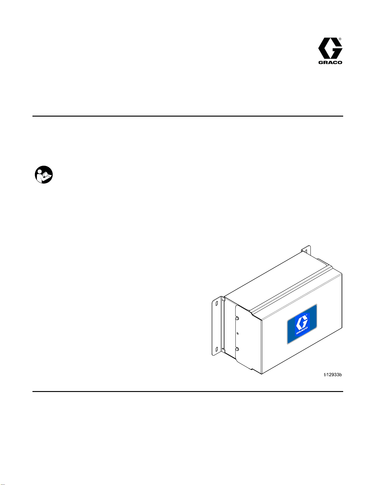
Advanced Web I
Installation and setup instructions to allow communication between a PC and various Graco devices, via
an ethernet. For professional use only. Not for use in explosive atmospheres or hazardous locations.
Important Safety Instructions
Read all warnings and instructions in this manual and in your system
manual. Save these instructions.
nterface Kit
EN
Kit 15V33
(AWI)
Kit 15V3
7, Advanced Web Interface
36, AWI Server Hub
PROVEN QUALITY. LEADING TECHNOLOGY.
Page 2
Warnings
The following
exclamation p
risks. When th
Warnings. Pr
the body of th
warnings are for the setup, use, grounding, maintenance and repair of this equipment. The
oint symbol alerts you to a general warning and the hazard symbol refers to procedure-specific
ese symbols appear in the body of this manual or on warning labels, refer backtothese
oduct-specific hazard symbols and warnings not covered in this section may appear throughout
is manual where applicable.
WARNING
FIRE AND EX
Flammable fumes, such as solvent and paint fumes, in work area can ignite or explode. To help
prevent fire and explosion:
• Use equipment only in well ventilated area.
• Eliminate all ignition sources; such as pilot lights, cigarettes, portable electric lamps, and
plastic drop cloths (potential static arc).
• Keep work
• Do not plug or unplug power cords, or turn power or light switches on or off when flammable
fumes are present.
• Ground all equipment in the work area. See Grounding instructions.
•Useonly
• Hold gun firmly to side of grounded pail when triggering into pail. Do not use pail liners unless
they are antistatic or conductive.
• Stop operation immediately if static sparking occurs or you feel a shock, Do not use
equipment until you identify and correct the problem.
• Keepaw
PLOSION HAZARD
area free of debris, including solvent, rags and gasoline.
grounded hoses.
orking fire extinguisher in the work area.
ELECTRIC SHOCK HAZARD
quipment must be grounded. Improper grounding, setup, or usage of the system can
This e
electric shock.
cause
• Turn off and disconnect power at main switch before disconnecting any cables and before
servicing or installing equipment.
• Connect only to grounded power source.
• All electrical wiring must be done by a qualified electrician and comply with all local codes
and regulations.
2
332459A
Page 3
WARNING
EQUIPMENT MISUSE HAZARD
Misuse can cause death or serious injury.
Warnings
• Do not operat
• Do not exceed the maximum working pressure or temperature rating of the lowest rated
system component. See Technical Data in all equipment manuals.
• Use fluids and solvents that are compatible with equipment wetted parts. See Technical Data
in all equipment manuals. Read fluid and solvent manufacturer’s warnings. For complete
information about your material, request MSDS from distributor or retailer.
• Do not leave
• Turn off all equipment and follow the Pressure Relief Procedure when equipment is not in use.
• Check equipment daily. Repair or replace worn or damaged parts immediately with genuine
manufacturer’s replacement parts only.
• Do not alte
and create
• Make sure all equipment is rated and approved for the environment in which youareusingit.
• Use equipment only for its intended purpose. Call your distributor for information.
• Route hos
• Do not kink or over bend hoses or use hoses to pull equipment.
• Keep children and animals away from work area.
•Complyw
e the unit when fatigued or under the influence of drugs or alcohol.
the work area while equipment is energized or under pressure.
r or modify equipment. Alterations or modifications may void agency approvals
safety hazards.
es and cables away from traffic areas, sharp edges, moving parts, and hot surfaces.
ith all applicable safety regulations.
332459A 3
Page 4

Related Manuals
Related Manuals
Manual Description Use For
313386
3A2040
3A2164
ProMix 2KS/3K
Informer Instructions/Parts Follow all instructions in 332459 first, thensee
ProControl 1KE Instructions/Parts Follow all instructions in 332459 first, then see Appendix
S Web Interfaces
All Installat
ProMix 2KS and
Manual 33245
Appendix B for specific Informer Settings and Operation
information.
B for specific ProControl 1KE Settings and Operation
information.
ion, Setup, and Operation information for
ProMix 3KS AWI or Basic Web Interface.
9 is not needed for the ProMix family.
4
332459A
Page 5
Installation
Overview
Installation
NOTE: Refer to
(the Informe
Manual 31338
The Advanced Web Interface (AWI) is an accessory that works with many Graco devices and gateways. The
AWI allows communication with a personal computer (PC) over an ethernet. With the AWI, users can view and
change system setup parameters and create reports from a remote PC. This manual contains installation and
setup information common to all devices. It includes sections on how to configure your computer, initialize the
system, configure the main system settings, and set up your network.
NOTE: Screen views in this manual are shown using Microsoft Windows 7.
Location
TheAWImodulemaybeinstalledinalocalnetwork
of Graco devices, such as a network of ProControl
1KEs. It also may be installed in a Local Area
Network (LAN).
Do not install equipment approved only for
non-hazardous location in a hazardous area.
Install the AWI near your system’s control module,
in a non-hazardous area.
this manual first, then look in your system manual for information specific to your system
r, for example, or the ProControl 1KE). ProMix 2KS and ProMix 3KS Users: Please refer to
6.
Mounting
1. See Dimensions, page 27.
2. Ensure that the wall and mounting hardware
are strong enough to support the weight of the
equipment, fluid, hoses, and stress caused
during operation.
3. Using the equipment as a template, mark the
mounting holes on the wall at a convenient height
for the operator and so equipment is easily
accessible for maintenance.
4. Drill mounting holes in the wall. Install anchors
as needed.
5. Bolt equipment securely.
332459A 5
Page 6
Installation
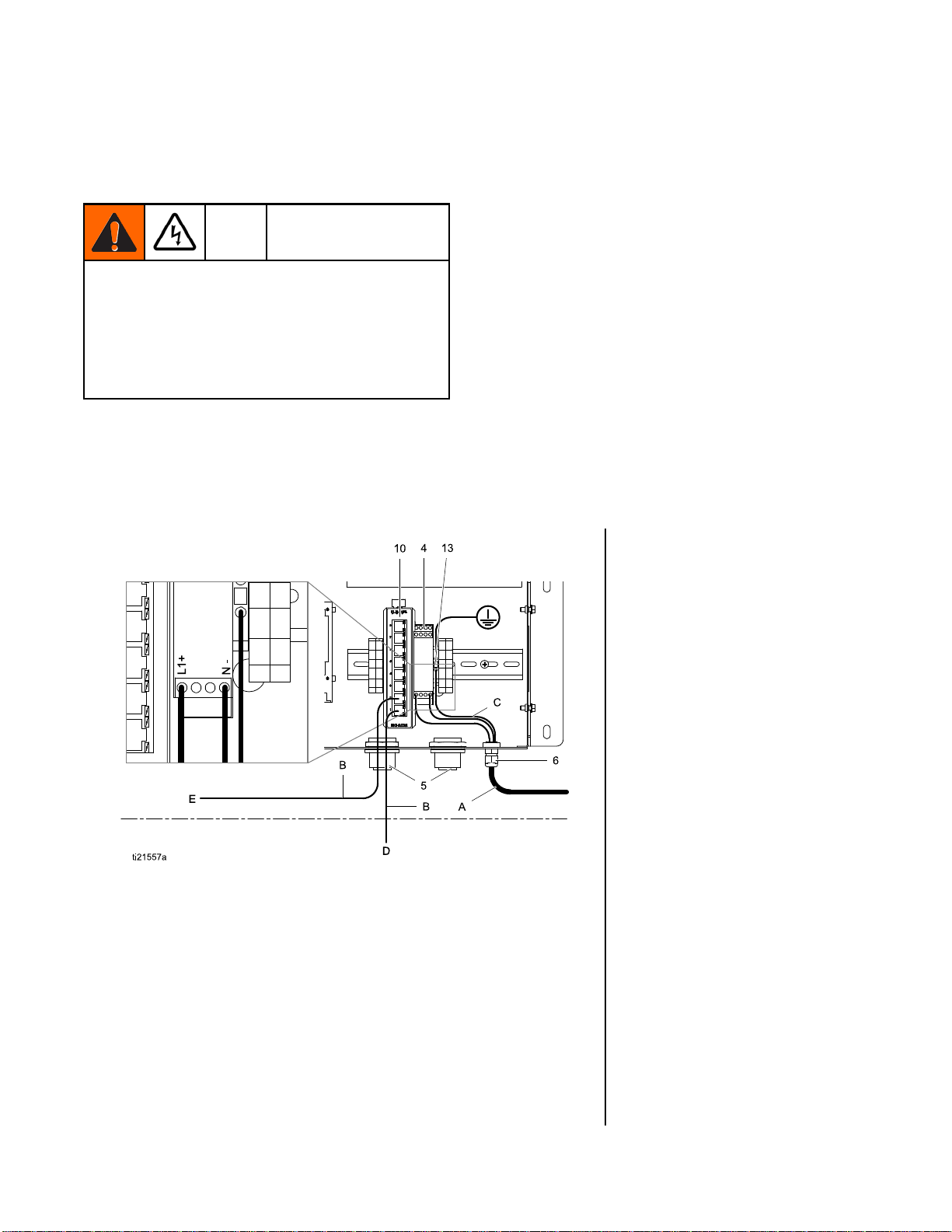
Connections
Make electrical and communication connections to
the AWI.
• To avoid electric shock, turn off power before
servicing.
• Shut off power at main circuit breaker.
• All electrical wiring must be done by a qualified
electrician and comply with all local codes and
regulations.
1. Connect the AWI to power.
a. Connect main power supply cord (A, not
supplied) through the strain relief to terminals
L1 (+) and N (-) on the power supply (4).
b. Connect power cord ground wire C) to the
terminal block (13).
2. Connect the AWI to another Graco device or
gateway and to a PC.
a. Shut off power to the Graco device (D). Also
shut off power at main circuit breaker.
b. Run a CAT5 cable through grommet from the
ethernet port on the Graco device or gateway
(D) and connect it to any port on the ethernet
switch (10) in the AWI .
c. Run another CAT5 cable from any port on
the ethernet switch (10) to the ethernet port
on a PC (E).
Key — Conections and
Installation Example
Supplied in AWI Module
4
POWER SUPPLY, 24 Vdc
5
GROMMET, cable entry
6
CONNECTOR, strain
relief
10
SWITCH, ethernet
13
BLOCK, terminal, ground
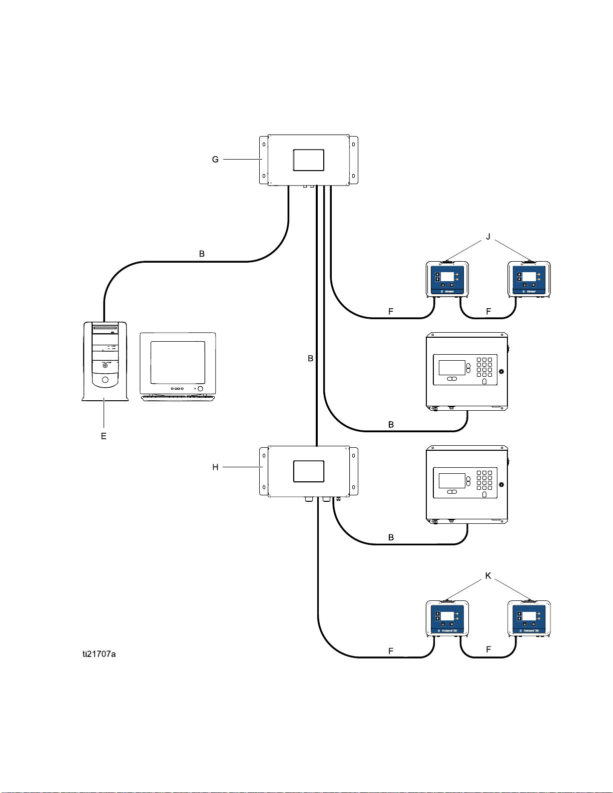
AWI Module
G
Accessories or
User-Supplied Components
A
Power Cord, user
supplied
B
Cable, CAT 5, user
supplied
C Ground wire from power
cord
D
Graco device or gateway
E Personal computer
F Fiber optic cable
HAWIHub
J
Informer Module
K
ProControl 1KE Module
6 332459A
Page 7
Installation
Installation Example
This sample installation is only a guide for setting up system communication. Contact your Graco distributor for
assistance in planning a system to suit your needs.
332459A
7
Page 8

Computer Configu
ration
Computer Confi
SetUpanAutom
The AWI requires an IP address obtained by your
computer. Set up your computer to obtain one
automatically.
1. Find the section for the browser that you use,
then follow the steps to set your computer to
obtain the IP address automatically.
• Windows XP
a. Click Start, then click Control Panel.
b. On the Control Panel window, double-click
Network Connections.
NOTE: Check the upper left corner of the
Control Panel screen. Click Switch to
Classic View to easily locate the Network
Connections icon.
c. Right-click Local Area Connection, then click
Properties.
d. On the Local Area Connection Properties
window, click Internet Protocol (TCP/IP).
Then click Properties.
e. Select Obtain an IP address automatically
and Obtain DNS server address
automatically.
f. Click OK to save the changes.
• Windows 7/Vista
a. Click the Windows icon, then click Control
Panel.
b. Under Network and Internet, click View
network status and tasks.
NOTE: At the upper right-hand corner of the
Control Panel window, you may change the
window’s view type. If you have Large icons
or Small Icons selected, you will click on
Network and Sharing Center instead.
atic IP Address
guration
e. Right-click L
Properties.
f. On the Local A
window, clic
(TCP/IPv4).
g. Select Obta
and Obtain D
automatica
h. Click OK to
• Windows 8
a. Press the Windows key on your keyboard to
show the Start screen, then click Desktop.
b. Right-click the Network icon located on the
bottom-right corner of the Desktop screen.
Then click Open Network and Sharing
Center.
c. Click Change adapter settings.
d. On the Ethernet Properties window, select
Internet Protocol Version 4 (TCP/IPv4). Then
click Properties.
e. Select Obtain an IP address automatically
and Obtain DNS server address
automatically.
f. Click OK to save the changes.
• Macin
a. Click the Apple icon, then click System
b. On the System Preferences window, click
c. On the Network window, look for the Show
d. Still on the Network window, look for the
tosh OS
Preferences.
Network.
field and select Built-In Ethernet.
TCP/IP tab. In the Configure IPv4 field,
select Using DHCP.
ocal Area Connection, then click
rea Connection Properties
k Internet Protocol Version 4
Then click Properties.
in an IP address automatically
NS server address
lly
.
save the changes.
c. Click Change adapter settings.
d. For Windows Vista, click Manage network
connections.
e. Click Apply Now.
2. Close your Control Panel and continue with
System Initialization.
8 332459A
Page 9

Computer Configu
ration
Set Up IP Addre
If the automatic configuration does not work or cannot
be used with your system, the IP address required by
the AWI can be set up manually.
1. In the previo
directions f
2. In the last st
Address.
Fill in the information, using the following
parameters.
IP Address 192.168.178.xxx
Gateway
Netmask 255.255.255.0
or your browser.
ep, choose Use the Following IP
ss Manually
us section, find and follow the
(210–224)
192.168.178.200
3. Then, select Use the Following DNS Server
Addresses. Fill in this address.
DNS
192.168.178.200
332459A 9
Page 10

Computer Configu
ration
System Initia
NOTE: System initialization must be done by an
administrator. This process is required only when
the system is first started.
NOTE: Do not c
it is configur
comes with DH
NOTE: Verify that the wireless connection is turned
off (disabled) before performing step 1.
1. Open a browser. Chrome 15 or above, Firefox
16 or above, or Internet Explorer 9 or above are
recommended.
2. Turn off any proxy server configurations.
3. Type http://gracoawi or http://192.168.178.200 in
the browser address bar, and press Enter.
4. The Welcome screen will appear. Click Next.
lization
onnect the system to a LAN unless
ed properly first. By default the system
CP and DNS servers enabled.
6. Initialization is complete. Click Finish.
7. The Login screen will appear. Type in the login
name and password you entered in Step 5. Click
Sign in. The Network screen will appear.
5. The Security screen will appear. The
administrator must fill in all fields. Click Next.
10 332459A
Page 11

Password Recovery
Computer Configu
ration
1. Ifyoutypeint
blocked. Click on the block icon
password recovery sequence.
2. Type in your login name, then click Next.
he wrong password, sign in will be
to initiate the
3. Type the answe
click Next.
4. If the answer matches the one entered in Step 5,
the system will prompt you for a new password.
Enter the new password twice, then click Next.
The system will return to the Login screen.
r to your secret question, then
332459A
11
Page 12

System Configura
tion
System Configu
ration
Settings Tab
Use the Settings tab to configure the main system
settings (Time, Language, Upgrade AWI, Accounts,
and Networking).
2
1
332459A
Page 13

System Configura
tion
System Time
Set the correct time and synchronize time settings.
1. Edit the infor
Click Save.
2. Click Sync to synchronize the AWI time
settings with the time settings on all connected
Graco devices. On the Sync screen, verify the
current time. If correct, click Sync. If incorrect,
click Cancel to return to the Settings tab and
make corrections.
mation in each field as required.
Language
Set the desired language of the screen text.
1. Click the arro
from the pull d
(default), C
German, Ital
Spanish.
2. Click Save.
w to select the desired language
own menu. Options are English
hinese (Simplified), Dutch, French,
ian, Japanese (Kanji), Korean, and
Upgrade AWI
Upgrade to the latest AWI software version.
Before using this screen, download the latest version
of AWI software to your computer. Contact your
Graco distributor for information.
1. Click
2. On the Upgrade popup, click on Choose File.
3. Locate the file you downloaded to your computer.
Highlight the filename. Click Upgrade.
NOTE: This process may take up to 5 minutes.
The system will indicate when the upgrade
process is done. If the system times out after
5 minutes, power off the unit and then power it
back on and log back in.
Upgrade.
332459A 13
Page 14

System Configura
Accounts
tion
The first person who logs in is automatically
designated as an Administrator. An Administrator
uses this screen to add a user or edit user information.
1. To add a new account, click
a. On the Add user popup window, enter
information into all the data fields. Click Add.
Add User.
2. To edit an existing account, click the Edit User
icon
a. On the Edit user popup window, enter
b. A check mark will appear in the top right
.
information into all the data fields. Click
Save.
NOTE: Do not change all users to the
status of User. At least one person must
have Admin status, to add users and edit
information.
corner when the save is complete.
b. A check mark will appear in the top right
corner when the save is complete.
3. To delete an existing account, click the Delete
User icon
Note: People who have a status of User see the
following Accounts section, and these are the only
changes available to them.
.
4
1
332459A
Page 15

Network
System Configura
tion
Local Network Configuration
In a local network mode, the AWI module is
configured for a closed network that includes a PC
and Graco devices. In this mode, AWI is set to a
static IP address (192.168.178.200). The system
enables DHCP and DNS servers.
1. On the Settings Tab, in the Network section,
select Local network.
2. Click Save, and when the confirmation screen
appears, click Confirm.
NOTE: Be sure there is no physical connection
to another existing LAN in local network mode. It
will lead to a possible disturbance to the network
operation.
Manual Configuration
In manual configuration mode, the AWI module
can be configured to operate on an existing local
area network (LAN). In this mode, the AWI is
assigned to a static IP address, gateway, and
netmask chosen by the user. The system will
disable DCHP and DNS servers. In addition, a
virtual network interface will be enabled (IP aliasing,
192.168.178.200/255.255.255.0).
1. To change to a manual network configuration,
connect and configure the AWI in local
network mode. See Connections, page 6 and
Computer Configuration, page 8 .
2. On the Settings Tab, in the Network section,
select Manual configuration.
3. Enter the IP address, gateway and netmask.
Contact your IS system administrator for
assistance.
NOTE: Make
network wi
4. Click Save
click Confi
Once the new settings are confirmed, the AWI will
disconnect the user computer. Reconnect the AWI
and computer. Reconfigure the user computer to
match the new LAN configuration. You can then login
to the AWI using the newly assigned IP address.
NOTE: If you change the addresses in this section,
be certain that the new adresses will work and be
sure to write them down. These addresses provide
access to the AWI program. If you change these
addresses and cannot remember the new ones, you
will not be able to access any AWI screens.
sure there is no other device on the
th a conflicting IP configuration.
.When the confirmation page appears,
rm.
332459A 15
Page 16

System Configura
tion
Recover IP Settings
If you have lost your IP settings and can no longer
access screens, you can force a network reset to
configure the AWI to the default Local Network
Configuration.
NOTICE
To avoid damage to the circuit board, wear Part No.
112190 grounding strap, and ground appropriately.
1. Turn off power to the AWI unit.
2. On the AWI computer board (TS-7800), remove
the jumper from JP1. Put it on DIO pin pair 1
(noted by dot).
3. Power up the AWI and wait one minute, then
power it down again.
4. Remove the jumper from DIO 1. Put it back on
JP1.
5. Power up the unit. The system will operate in
default Local Network Configuration. To login,
type http://gracoawi or http://192.168.178.200 in
the browser address bar. Press Enter.
6. The Login screen appears. Log in with the login
and password you set up. Your settings will be
intact.
JP-1
DIO-1
NOTICE
tain you move the jumper only to DIO
Be cer
air 1. Other placement of the jumper will
pin p
ge the board.
dama
ti21708a
16 332459A
Page 17

Network Tab
System Configura
tion
Thefirsttimey
show no Networ
ou click on the Network Tab it will
ked Devices.
1. Click Devices >> Search inthecolumnatthe
far left of the screen. The system will search for
Graco devices that already are connected to the
AWI.
NOTE: The search may take several minutes.
a. Successful Search: A window appears with
a listing of all networked devices. A check is
in the box for each device, indicating it will
be added.
332459A
17
Page 18

System Configura
b. Click Add. The Network Tab appears, now
populated with devices.
tion
NOTE: The located devices do not have
names. See your system manual for
directions on how to assign names, along
with other setup information specific to each
Graco device.
18 332459A
Page 19

System Configura
tion
c. Check that all device icons are blue, with the
system name above. If a device is grayed
out and says Offline, check the connection to
that device, then click Refresh.
d. Unsuccessful Search: An exclamation point
appears in the upper right hand corner of the
screen, indicating the system did not locate
any devices. Click Cancel.Adddevices
manually.
332459A 19
Page 20

System Configura
tion
Add or Remove Gateways
The AWI module communicates with Graco devices
through gateways installed in the system. The AWI
Module comes with default gateways set. Use the
Gateways section to add additional gateways through
which the AWI will communicate with Graco devices.
Add gateways before adding additional devices.
1. Click Gatewa
shows the gat
TCP Local is
ProMix user
gateway ins
users.
NOTE: To use the AWI Module,
Informer/ProControl 1KE users must have
purchased and installed Communication Kits
24N977 and 24N978. See Graco Manual 332356
for further information.
ys >> Remove. The popup window
eways that already are installed.
the default gateway installed for
s. Modbus TCP Local is the default
talled for Informer/ProControl IKE
2. To add a gateway, click Gateway >> Add.Adda
gateway if you accidentally removed the default
gateway, or to extend your network by adding
additional Modbus Gateway kits.
a. Gateway Type, ProMix: In the drop down
menu, select tcp_local.
b. Gateway Type, Informer/ProControl 1KE: In
the drop down menu, select modbus_tcp_rtu.
c. In the Name field, type an identifying name
of your choosing, for example Factory1,or
Line3.
NOTE: Do not remove these default gateways. If
they are removed accidentally, see Step 2d for
information on how to restore them.
d. In the Address field, type the IP address of
the gateway, established when you installed
that particular gateway.
NOTE: if you are restoring the default
gateway, the IP address is 192.168.178.205.
Be sure to eliminate
address only.
http://.
Use the IP
20 332459A
Page 21

Add or Remove Devices
System Configura
tion
After gateways are set up, use the Devices section
to add or remove Graco devices.
1. Click Devices
a. Gateway drop down: Choose a gateway
through which the AWI will communicate
with Graco devices. For example, if you are
adding a ProMix, select TCP Local.Ifyou
are adding an Informer or a ProControl 1KE,
select Modbus TCP Local.
b. Device name: Type the name of your
choosing in the field, for example, Informer2.
c. Device address, ProMix: Type in the IP
address that you set up on the EasyKey.
d. Device address, Informer or ProControl 1KE:
Type in the modbus addresses (1–247) that
you set up.
>> Add.
2. Click Add.
a. Successful Ad
(briefly) in th
screen. Then,
the new devic
b. Unsuccessfu
appears in th
screen. Clic
select Gate
that your ga
not correct
again, with
adding you
d: A check mark appears
e upper right hand corner of the
the Network Tab appears with
e listed.
l Add: An exclamation point
e upper right hand corner of the
k Cancel. On the Network Tab
ways >> Remove. Double check
teway address is correct. If it is
, click Remove. Add the gateway
the correct address. Then try
r device again.
332459A
21
Page 22

System Configura
Materials Tab
tion
Use the Materi
Organic Compo
Pollutants (H
your system, f
by your Graco
manufacture
MSDS sheet pr
AP) for each material being used in
r’s part number, are available on the
als Tab to enter information on Volatile
unds (VOC) and Hazardous Air
or material reporting, if supported
device. This information, and the
ovided by the material manufacturer.
1. Use the drop do
Gram/Liter fo
2. To add a new mat
Enter the val
3. To delete a material, click the Minus button
4. Click Save to save your changes. A check mark
appears wh
wn menu to select Lbs/Gal or
rtheVOC.
erial, click the Plus button
ues in the data fields.
en the save is complete.
.
.
NOTE: Installation and general system configuration are complete. Refer to your system
manual for operation and setup information specific to your system (the Informer, for
example, or the ProControl 1KE). ProMix 2KS and ProMix 3KS Users: Please refer
to Manual 313386.
2
2
332459A
Page 23

Replace AWI Board
Replace AWI Boar
d
•Toavoidelect
servicing.
• Shut off powe
• All electric
electrician
regulation
ric shock, turn off power before
r at main circuit breaker.
al wiring must be done by a qualified
and comply with all local codes and
s.
NOTICE
To avoid damage to the circuit board, wear Part No.
112190 grounding strap and ground appropriately.
1. Shut off po
2. Shut off po
3. Open the A
4. Disconne
the board
wer.
wer at main circuit breaker.
WI module.
ct the cable (15) and wires (17, 18) from
(22).
5. Remove the scr
6. Install the ne
and wires (17,
w board. reconnect the cable (15)
ews and board (22).
18).
332459A 23
Page 24

Parts
Parts
Kit 15V337 Advanced Web Interface Module
Connect to 4.
Connect to 10.
Connect to 22.
Ref.
1 15V339 PANEL 1
2
3
4 120369
5
6 111987
7
8▲ 186620 LABEL, ground symbol 1
9
10 15V342
11 120838
12 103833
Part Description
15T752
———
15V345
———
———
COVER
DIN RAIL 1
SUPPLY UNIT, power,
24Vdc
GROMMET, cable entry
CONNECTOR, cord strain
relief
WIREWAY 1
COVER, wireway
SWITCH, ethernet
BLOCK, clamp end
SCREW, #10 —32
UNF-2A
Wiring Diagrams
Qty.
1
1
2
1
1
1
2
4
Ref.
13 112443
15 121994
17
18
21 15V340
22 258355
25 ▲ 15W776 LABEL, warning 1
28
▲
Replacement Danger and Warning labels, tags,
and cards are available at no cost.
Items marked — — — are not sold separately.
Part Description
BLOCK, terminal ground
CABLE, CAT5
———
———
———
WIRE, copper, 16 ga; 9 in
(230 mm)
WIRE, copper, 16 ga; 9 in
(230 mm)
STANDOFF, board
BOARD, server
SCREW, machine,
serrated hex-head
Qty.
1
1
1
1
4
1
4
4
2
332459A
Page 25

Parts
Kit 15V336 Adv
Connect to 4.
anced Web Interface Server Hub
Wiring Diagrams
Connect to 10.
Part Description
Ref.
1 15V339 PANEL 1
2
15T752
———
3
4 120369
5
15V345
6 111987
———
7
8▲ 186620 LABEL, ground symbol 1
———
9
10 15V342
11 120838
COVER
DIN RAIL 1
SUPPLY UNIT, power,
24Vdc
GROMMET, cable entry
CONNECTOR, cord strain
relief
WIREWAY 1
COVER, wireway
SWITCH, ethernet
BLOCK, clamp end
Qty.
1
1
2
1
1
1
2
Part Description
Ref.
12 103833
13 112443
———
17
———
18
25 ▲ 15W776 LABEL, warning 1
———
28
▲
Replacement Danger and Warning labels, tags,
SCREW, #10 —32 UNF-2A
BLOCK, terminal ground
WIRE, copper, 18 in. (46
cm); not shown
WIRE, copper, 18 in. (46
cm); not shown
SCREW, machine,
serrated hex-head
and cards are available at no cost.
Items marked — — — are not sold separately.
Qty.
4
1
2
2
4
332459A 25
Page 26

Accessories
Accessories
Cables
• 121998, CAT 5, RJ45 Cable, 25 ft (7.6 m)
• 121999, CAT 5, RJ45 Cable, 50 ft (15 m)
• 15V842, CAT 5, RJ45 Cable, 100 ft (30 m)
• 15V843, CAT 5, RJ45 Cable, 200 ft (61 m)
• 16M172, Fiber Optic Cable, 50 ft (15 m)
• 16M173, Fiber Optic Cable, 100 ft (30 m)
26 332459A
Page 27

Dimensions
KEY
Dimensions
in. mm.
A 16.57 420.9
B 15.07 382.8
C
D 8.71 221.2
E 6.45 163.8
5.31 134.9
332459A
27
Page 28

Graco Standard Warranty
Graco warrants all equipment referenced in this document which is manufactured by Graco and bearing its
name to be free from defects in material and workmanship on the date of sale to the original purchaser for
use. With the exception of any special, extended, or limited warranty published by Graco, Graco will, for a
period of twelve months from the date of sale, repair or replace any part of the equipment determined
by Graco to be defective. This warranty applies only when the equipment is installed, operated and
maintained in accordance with Graco’s written recommendations.
This warranty does not cover, and Graco shall not be liable for general wear and tear, or any malfunction,
damage or wear caused by faulty installation, misapplication, abrasion, corrosion, inadequate or improper
maintenance, negligence, accident, tampering, or substitution of non-Graco component parts. Nor shall
Graco be liable for malfunction, damage or wear caused by the incompatibility of Graco equipment
with structures, accessories, equipment or materials not supplied by Graco, or the improper design,
manufacture, installation, operation or maintenance of structures, accessories, equipment or materials
not supplied by Graco.
This warranty is conditioned upon the prepaid return of the equipment claimed to be defective to an
authorized Graco distributor for verification of the claimed defect. If the claimed defect is verified, Graco
will repair or replace free of charge any defective parts. The equipment will be returned to the original
purchaser transportation prepaid. If inspection of the equipment does not disclose any defect in material
or workmanship, repairs will be made at a reasonable charge, which charges may include the costs of
parts, labor, and transportation.
THIS WARRANTY IS EXCLUSIVE, AND IS IN LIEU OF ANY OTHER WARRANTIES, EXPRESS OR
IMPLIED, INCLUDING BUT NOT LIMITED TO WARRANTY OF MERCHANTABILITY OR WARRANTY
OF FITNESS FOR A PARTICULAR PURPOSE.
Graco’s sole obligation and buyer’s sole remedy for any breach of warranty shall be as set forth above.
The buyer agrees that no other remedy (including, but not limited to, incidental or consequential damages
for lost profits, lost sales, injury to person or property, or any other incidental or consequential loss) shall
be available. Any action for breach of warranty must be brought within two (2) years of the date of sale.
GRACO MAKES NO WARRANTY, AND DISCLAIMS ALL IMPLIED WARRANTIES OF
MERCHANTABILITY AND FITNESS FOR A PARTICULAR PURPOSE, IN CONNECTION WITH
ACCESSORIES, EQUIPMENT, MATERIALS OR COMPONENTS SOLD BUT NOT MANUFACTURED BY
GRACO. These items sold, but not manufactured by Graco (such as electric motors, switches, hose, etc.),
are subject to the warranty, if any, of their manufacturer. Graco will provide purchaser with reasonable
assistance in making any claim for breach of these warranties.
In no event will Graco be liable for indirect, incidental, special or consequential damages resulting from
Graco supplying equipment hereunder, or the furnishing, performance, or use of any products or other
goods sold hereto, whether due to a breach of contract, breach of warranty, the negligence of Graco, or
otherwise.
FOR GRACO CANADA CUSTOMERS
The Parties acknowledge that they have required that the present document, as well as all documents,
notices and legal proceedings entered into, given or instituted pursuant hereto or relating directly or
indirectly hereto, be drawn up in English. Les parties reconnaissent avoir convenu que la rédaction du
présente document sera en Anglais, ainsi que tous documents, avis et procédures judiciaires exécutés,
donnés ou intentés, à la suite de ou en rapport, directement ou indirectement, avec les procédures
concernées.
Graco Information
For the latest information about Graco products, visit www.graco.com.
For patent information, see www.graco.com/patents.
To place an order, contact your G
Phone: 612-623-6921 or Toll Free: 1-800-328-0211 Fax: 612-378-3505
All written and visual data contained in this document reflects the latest product information available at the time of publication.
Graco reserves the right to make changes at any time without notice.
GRACO INC. AND SUBSIDIARIES • P.O. BOX 1441 • MINNEAPOLIS MN 55440-1441 • USA
Copyright 2013, Graco Inc. All Graco manufacturing locations are registered to ISO 9001.
raco Distributor or call to identify the nearest distributor.
Original Instructions. This manual contains English. MM 332459
Graco Headquarters: Minneapolis
International Offices: Belgium, China, Japan, Korea
www.graco.com
 Loading...