

Page 1
Instructions
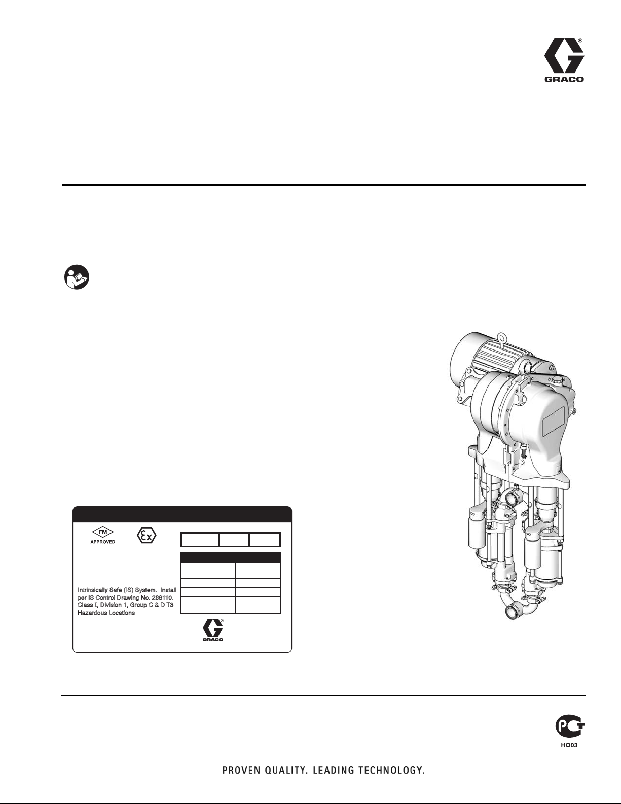
15J755 Sensor Circuit
Option
311603C
To upgrade E-Flo® Electric Circulation Pumps to include the sensor circuit option.
For professional use only.
Important Safety Instructions
Read all warnings and instructions in this manual
and in E-Flo Repair-Parts manual 311594. Save
these instructions.
E-Flo Pump with 15J755 Sensor
Circuit Option installed.
ENG
The following hazardous location listings
apply to the sensor circuit (item 25) only.
Circuit Assembly Intrinsic Safe Control
USC
Conforms to
FM std 3600 &3610
CAN/CSA 22.2 No 157-92
& No. 1010.1-92
for use in Class I Div 1
Group C & D T3
Hazardous locations
Intrinsically Safe (IS) System. Install
per IS Control Drawing No. 288110.
Class I, Division 1, Group C & D T3
Hazardous Locations
Read Instruction Manual Warning: Substitution of components
may impair intrinsic safety.
MIN / MAX TEMP RANGE: 0° - 50°C (32° - 122°F)
EEx ib IIB
FM 06 ATEX 0025U
PART NO.
II 2 G
288343
Intrinsic Safe Input Parameters
Ui
Ii
Pi
Ci
Li
TDC Circuit
15 V
60 mA
200 mW
220 nF
280 uH
SERIES SERIAL
Pressure Circuit
35 V
200 mA
1.4 W
.036 uF
.44 uH
GRACO INC.
P.O. Box 1441
Minneapolis, MN
55440 U.S.A.
Artwork No. 293140
ti8317b
Page 2
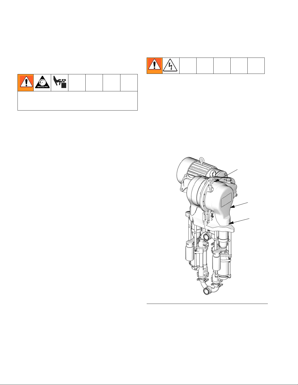
Pressure Relief Procedure
Pressure Relief
Procedure
System pressure can cause the pump to cycle unexpectedly, which could result in serious injury from
splashing or moving parts.
1. Set START/STOP switch to STOP.
2. Push in SECURE DISABLE switch.
3. Open the back pressure regulator and all fluid drain
valves in the system, having a waste container
ready to catch drainage. Leave open until you are
ready to pressurize system again.
4. Check that pressure gauges on fluid supply and
return lines read zero. If gauges do not read zero,
determine cause and carefully relieve pressure by
VERY SLOWLY loosening a fitting. Clear obstruction before pressurizing system again.
Kit Installation
1. Jog the motor to bring the stand side lower to the
bottom of its stroke.
2. Relieve pressure, page 2.
3. Shut off electrical power to the unit.
4. See F
5. See F
IG. 1. Remove two screws (12) and the cover
(32).
IG. 3, page 4. Remove six screws (12), the cir-
cuit board cover (B), and the gasket (33).
12*
Kit Parts
NOTE: Sensor Circuit Kit 15J755 includes all parts to
add the optional sensor circuit to a pump. Parts included
in the kit are marked with an asterisk, for example (12*).
Use all the new parts in the kit.
Ref.
No. Part No. Description Qty
12* 116719 SCREW, 8-32 hex washer head
25 n/a SENSOR CIRCUIT; includes items
25a-25c
25a* n/a PRESSURE TRANSDUCER
25b* n/a TDC SENSOR
25c* n/a CIRCUIT BOARD
32* n/a COVER, side opposite motor
33* n/a GASKET, circuit board
35* n/a CONNECTOR, strain relief, 45°
36* n/a LABEL, calibration
41* 111316 O-RING; chemically resistant fluoro-
elastomer
42* n/a ADAPTER, transducer
43* n/a NUT, transducer
44* n/a CONDUIT, transducer
58* n/a SPACER; brass
14
1
1
1
1
1
1
1
FIG. 1. Remove Cover
1
1
1
1
1
1
32*
12*
ti8317b
Parts designated n/a are not available separately.
2 311603C
Page 3

6. See FIG. 3, page 4. Apply medium strength thread
lock to the 45° connector (35*). Install the connector
(35*), nut (43*), and conduit (44*) in the gear housing, oriented as shown.
7. Unscrew the plug from the gear housing cavity (C)
and clean old sealant from the housing. Apply pipe
sealant and screw the TDC sensor (25b*) into the
gear housing. Torque to 66-78 in-lb (7.4-8.8 N•m).
NOTE: TDC sensor nuts are locked in place to ensure
correct positioning. Do not adjust.
Pressure Sensor Calibration Information
7
Torque to 15-20 ft-lb (21-27 N•m).
7
7
*43
*44
*42
58*
25a*
8. Install the circuit board (25c*) using four screws
(12*).
9. Connect the TDC cable (25b*) to J2 on the circuit
board (25c*).
10. Connect the IS circuit field wire to J2 and J3. See
the Electrical Schematic in the E-Flo Repair-Parts
Manual 311594.
11. See F
IG. 2. Install one new black o-ring (41*) and
the new brass spacer (58*) on the transducer
(25a*).
12. Thread the transducer’s cable (25a*) through the
adapter (42*) and conduit (44*). Connect the cable
to J1 on the circuit board (25c*). See F
13. See F
IG. 2. At the pump outlet manifold (D), remove
IG. 3.
the plug. Insert the transducer into the outlet manifold (D). Torque the adapter (F) first, then the nut (E)
to 15-20 ft-lb (21-27 N•m).
14. See F
IG. 3, page 4. Install the new gasket (33*), the
cover (B), and six screws (12*).
*41
D
F
IG. 2. Pressure Transducer
ti8721a
Pressure Sensor
Calibration Information
Pressure sensor information (Pr 20.34, 20.35, and
20.36) for your system must be keyed into the Variable Frequency Drive before system start-up.
To prevent accidental change of pressure sensor calibration parameters, they are locked by Pr 20.16. To
enter calibration parameters, perform the following
steps:
a. Set Pr 20.16 to 777, to unlock pressure sensor
parameters.
15. Attach the label (36*) to the cover (B).
b. Enter calibration parameters Pr 20.34, 20.35,
and 20.36.
16. Enter calibration information found on the label (36*)
into the VFD. See Pressure Sensor Calibration
Information.
17. See F
IG. 1. Reinstall the cover (32*) with two screws
(12*).
c. Set Pr 20.16 to 0 to lock pressure sensor
parameters.
Calibration Parameters from the label:
Pr 20.34 – Zero Calibration
Pr 20.35 – Calibration Pressure
Pr 20.36 – High Calibration
311603C 3
Page 4

Pressure Sensor Calibration Information
25c*
25b*
C
25b*
11
12*
25a*
36*
25c*
33*
B
ti8725a
35*
44*
11
Torque to 66-78 in-lb (7.4-8.8 N•m).
FIG. 3. Circuit Board Connections
4 311603C
Page 5

Pressure Transducer Calibration Procedure
Pressure Transducer Calibration Procedure
E-Flo pressure sensor must be calibrated against an
instrument grade High Precision Pressure Transducer,
which should be installed near the E-Flo pressure sensor.
1. Ensure that the High Precision Pressure Transducer
calibration is up to date.
2. Set Pr 20.16 to 777, to unlock pressure sensor
parameters.
3. Calibrate Low Pressure Point as follows:
a. Ensure that system is not pressurized. Calibra-
tion instrument pressure reading should be 0
psi.
b. Use Keypad to navigate to Pr 20.33; monitor its
reading for 5 – 10 seconds to determine its
average value. Make a record of it.
c. Navigate to Pr 20.34 and enter the recorded
average value of Pr 20.33.
4. Calibrate the High Pressure Point as follows:
a. Pressurize the system to 250 – 275 psi.
b. Keep the system pressurized and ensure that
pressure does not fluctuate.
c. Take a pressure reading from the calibration
instrument and make a record of it.
d. Navigate to Pr 20.35 and enter the recorded
system pressure.
e. Navigate to Pr 20.33; monitor its reading for
5-10 seconds to determine its average value.
Make a record of it.
f. Navigate to Pr 20.36 and enter the recorded
value of Pr 20.33.
5. Set Pr 20.16 to 0 to lock pressure sensor parame-
ters.
6. Verify pressure calibration.
a. Relieve system pressure.
b. Navigate to Pr 20.31 and verify that its reading
is within the range of 0-3 psi.
c. Pressurize the system to about 100 psi. Verify
that reading of Pr 20.31 is within +/- 2.5 psi of
the system pressure.
Do not exceed pressure rating of the system! If system
is rated to a pressure lower then 250 psi, use maximum allowable rated pressure. Refer to Operation
Manual 311593.
d. Pressurize system to about 250 psi. Verify that
reading of Pr 20.31 is within +/- 2.5 psi of the
system pressure.
311603C 5
Page 6

Graco Standard Warranty
Graco warrants all equipment referenced in this document which is manufactured by Graco and bearing its name to be free from defects in
material and workmanship on the date of sale to the original purchaser for use. With the exception of any special, extended, or limited warranty
published by Graco, Graco will, for a period of twelve months from the date of sale, repair or replace any part of the equipment determined by
Graco to be defective. This warranty applies only when the equipment is installed, operated and maintained in accordance with Graco’s written
recommendations.
This warranty does not cover, and Graco shall not be liable for general wear and tear, or any malfunction, damage or wear caused by faulty
installation, misapplication, abrasion, corrosion, inadequate or improper maintenance, negligence, accident, tampering, or substitution of
non-Graco component parts. Nor shall Graco be liable for malfunction, damage or wear caused by the incompatibility of Graco equipment with
structures, accessories, equipment or materials not supplied by Graco, or the improper design, manufacture, installation, operation or
maintenance of structures, accessories, equipment or materials not supplied by Graco.
This warranty is conditioned upon the prepaid return of the equipment claimed to be defective to an authorized Graco distributor for verification of
the claimed defect. If the claimed defect is verified, Graco will repair or replace free of charge any defective parts. The equipment will be returned
to the original purchaser transportation prepaid. If inspection of the equipment does not disclose any defect in material or workmanship, repairs will
be made at a reasonable charge, which charges may include the costs of parts, labor, and transportation.
THIS WARRANTY IS EXCLUSIVE, AND IS IN LIEU OF ANY OTHER WARRANTIES, EXPRESS OR IMPLIED, INCLUDING BUT NOT LIMITED
TO WARRANTY OF MERCHANTABILITY OR WARRANTY OF FITNESS FOR A PARTICULAR PURPOSE.
Graco’s sole obligation and buyer’s sole remedy for any breach of warranty shall be as set forth above. The buyer agrees that no other remedy
(including, but not limited to, incidental or consequential damages for lost profits, lost sales, injury to person or property, or any other incidental or
consequential loss) shall be available. Any action for breach of warranty must be brought within two (2) years of the date of sale.
GRACO MAKES NO WARRANTY, AND DISCLAIMS ALL IMPLIED WARRANTIES OF MERCHANTABILITY AND FITNESS FOR A
PARTICULAR PURPOSE, IN CONNECTION WITH ACCESSORIES, EQUIPMENT, MATERIALS OR COMPONENTS SOLD BUT NOT
MANUFACTURED BY GRACO. These items sold, but not manufactured by Graco (such as electric motors, switches, hose, etc.), are subject to
the warranty, if any, of their manufacturer. Graco will provide purchaser with reasonable assistance in making any claim for breach of these
warranties.
In no event will Graco be liable for indirect, incidental, special or consequential damages resulting from Graco supplying equipment hereunder, or
the furnishing, performance, or use of any products or other goods sold hereto, whether due to a breach of contract, breach of warranty, the
negligence of Graco, or otherwise.
FOR GRACO CANADA CUSTOMERS
The Parties acknowledge that they have required that the present document, as well as all documents, notices and legal proceedings entered into,
given or instituted pursuant hereto or relating directly or indirectly hereto, be drawn up in English. Les parties reconnaissent avoir convenu que la
rédaction du présente document sera en Anglais, ainsi que tous documents, avis et procédures judiciaires exécutés, donnés ou intentés, à la suite
de ou en rapport, directement ou indirectement, avec les procédures concernées.
Graco Information
For the latest information about Graco products, visit www.graco.com.
TO PLACE AN ORDER, contact your Graco distributor or call to identify the nearest distributor.
Phone: 612-623-6921 or Toll Free: 1-800-328-0211 Fax: 612-378-3505
All written and visual data contained in this document reflects the latest product information available at the time of publication.
Graco reserves the right to make changes at any time without notice.
Original instructions. This manual contains English. MM 311603
Graco Headquarters: Minneapolis
International Offices: Belgium, China, Japan, Korea
GRACO INC. P.O. BOX 1441 MINNEAPOLIS, MN 55440-1441
Copyright 2007, Graco Inc. is registered to ISO 9001
www.graco.com
Revised 09/2010
 Loading...