

Page 1
Instructions
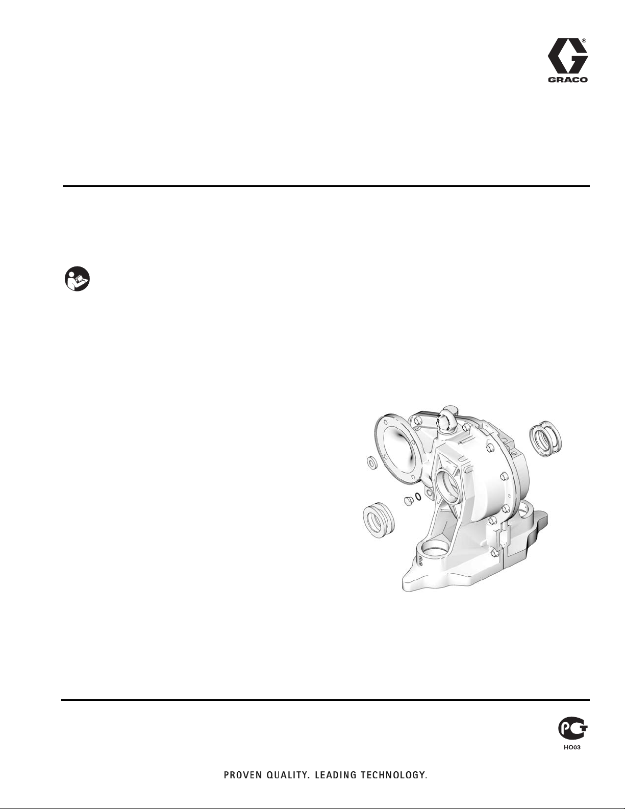
15H871 Reducer Seal
Replacement Kit
To replace gear reducer seals on E-Flo® Electric Circulation Pumps.
For professional use only.
Important Safety Instructions
Read all warnings and instructions in this manual
and in E-Flo Repair-Parts manual 311594. Save
these instructions.
311597C
ENG
ti8682a
Page 2

Pressure Relief Procedure
Pressure Relief
Procedure
System pressure can cause the pump to cycle unexpectedly, which could result in serious injury from
splashing or moving parts.
1. Set START/STOP switch to STOP.
2. Push in SECURE DISABLE switch.
3. Open the back pressure regulator and all fluid drain
valves in the system, having a waste container
ready to catch drainage. Leave open until you are
ready to pressurize system again.
4. Check that pressure gauges on fluid supply and
return lines read zero. If gauges do not read zero,
determine cause and carefully relieve pressure by
VERY SLOWLY loosening a fitting. Clear obstruction before pressurizing system again.
Kit Installation
1. Jog the motor to bring the motor-side pump to the
bottom of its stroke.
NOTE: Repair the motor side seals first, as follows.
2. Relieve pressure, page 2.
3. Shut off electrical power to the unit.
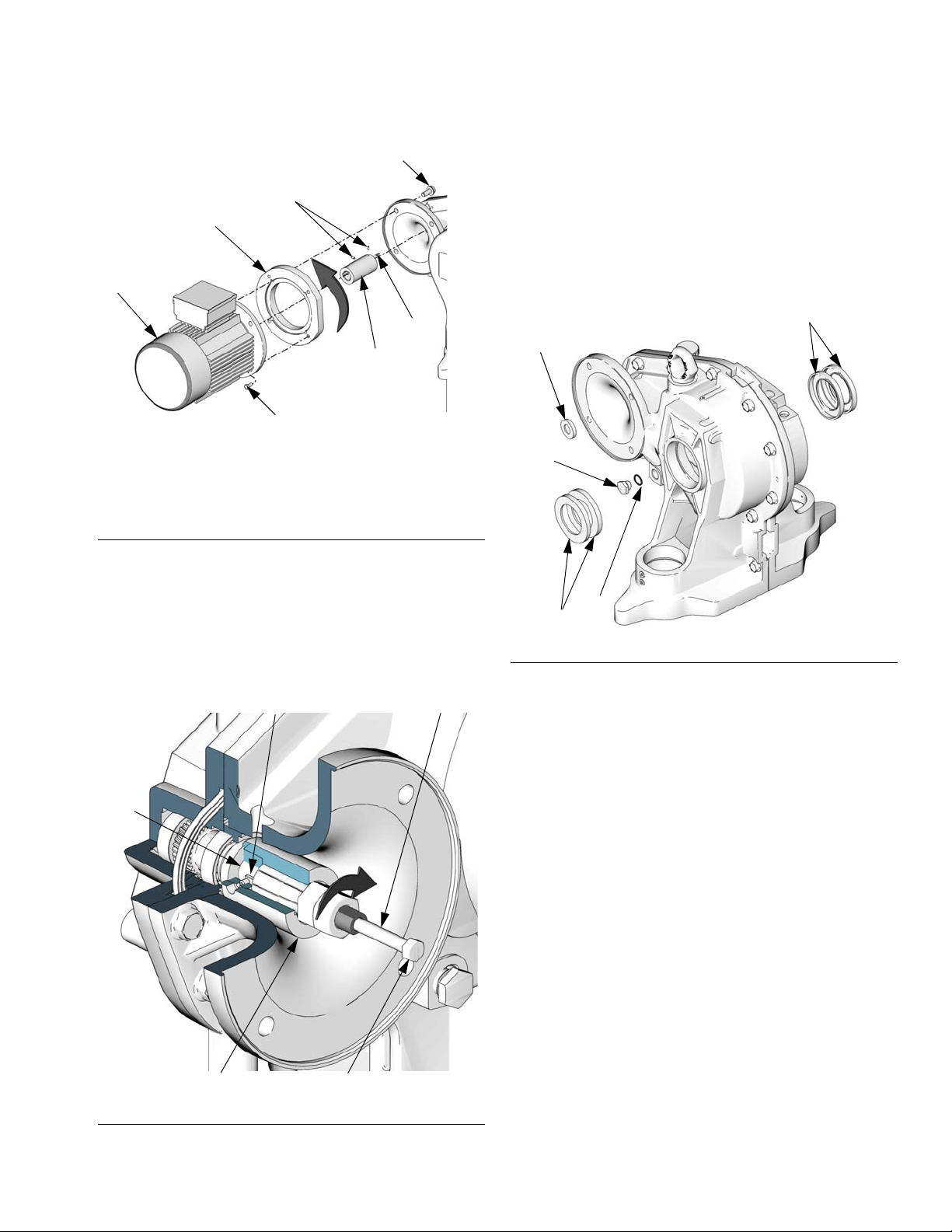
4. Remove the motor and coupler as follows:
a. See F
IG. 1 for NEMA 184/182 TC Frame electric
motors. See F
Frame electric motors. While one person supports the motor (19), remove the screws (37).
Pull the motor away from the gear reducer.
IG. 2 for IEC 112M/B5 or 100L/B5
37*
Kit Parts
NOTE: Gear Reducer Seal Replacement Kit 15H871
includes parts to replace all gear reducer seals. Parts
included in the kit are marked with an asterisk, for example (5*). Use all the new parts in the kit.
NOTE: Output Shaft Seal Tool Kit 15J926 is available for
removal and installation of the output shaft seals.
Ref.
No. Part No. Description Qty
5* n/a SCREW, cap, socket-head; 5/8-11
x 3 in. (76 mm)
12* 116719 SCREW, 8-32 hex washer head
31* 100664 SCREW, set, socket-head; 1/4-20
x 1/2 in. (13 mm)
37
109* n/a SEAL, input shaft
116* n/a SEAL, output
119* 120395 GASKET, oil plug
n/a
SCREW, cap, flange-head; 1/2-13 x
1.25 in. (31 mm)
20
*31
19
31*
28
Motor Rotation
4
4
2
4
1
4
1
(counter-clockwise as viewed from fan end)
FIG. 1. NEMA 184/182 TC Frame Electric Motors
ti8726a
Parts designated n/a are not available separately.
2 311597C
Page 3
19
MA
*31
28
37*
20
Kit Installation
5. Remove four screws (12) and both covers (21, 32).
F
IG. 5 shows the cover (32) on the stand side; the
motor side cover is (21).
6. See F
IG. 4. On the motor side of the gear reducer,
unscrew the oil drain plug (118) and remove the
gasket (119). Pierce the input seal (109) with a
hardened sheet metal screw and pull it out.
116*
109*
MS
Motor Rotation
(counter-clockwise as viewed from fan end)
F
IG. 2. IEC 112M/B5 or 100L/B5 Frame Electric
Motors
b. See FIG. 3. Loosen both setscrews (31). Insert
the coupler removal tool (T) into the coupler
(28). Turn nut clockwise until tight, then pull the
coupler off the gear reducer input shaft (105) by
turning hex-head screw (HS) clockwise.
20
105
ti9007a
T
118
116*
119*
ti8682a
FIG. 4. Gear Reducer Seals
7. Place tape over the input shaft keyway, to prevent
damage to the new seal. Pack the input shaft seal
cavity with Part No. 107411 Grease. Install the input
seal (109*) with the lip facing in, until the seal contacts the shoulder of the gear reducer housing.
Remove the tape.
8. Install the gasket (119*) on the oil drain plug (118)
and screw the plug into the gear reducer. Tighten
securely.
28
F
IG. 3. Motor Coupler Removal
311597C 3
HS
ti8743a
Page 4

Kit Installation
9. Disconnect the crank arm as follows:
a. Place a clean rag over the top of the slider cylin-
der (2) to prevent debris from falling into the
slider assembly during disassembly.
b. Place a 3/4 in. wrench on the slider piston (9)
flats (just above the coupling nut), to keep the
slider piston/connecting rod from turning when
you are loosening the coupling nut (14). Orient
the wrench so it is braced against one of the tie
rods (3). Applying excessive force to the slider
piston/connecting rod can shorten the life of the
lower pin bearing.
c. Using a 1-5/8 in. open-end wrench, unscrew the
coupling nut (14) from the slider piston (9) and
let it slide down onto the pump piston rod. Be
careful not to lose the collars (13).
9
Place clean rag over slider cylinder (2).
12
Apply antiseize lubricant to screw (5) threads. Torque
key-side screw to 210-230 ft-lb (283-310 N•m) first, then
torque gap side screw to 210-230 ft-lb (283-310 N•m).
9
5
38
39
12
d. See F
IG. 6. Using a 1/2 in. hex driver, unscrew
the two cap screws (5). Remove the crank arm
cap (38) and key (39). If necessary, use a plastic hammer to break these parts loose.
e. See F
IG. 7. Rotate the crank arm (4) to allow it
to be removed from the output shaft (OS).
9
Place clean rag over slider cylinder (2).
10
Hold slider piston (9) flats with 3/4 in. wrench, and brace
against tie rod (3).
9
3
10
14
F
IG. 5. Remove Coupling Nut (Stand Side Shown)
12
ti9223b
32
IG. 6. Remove Crank Arm Cap
F
4
CR
OS
F
IG. 7. Rotate Crank Arm
10. Remove the two output seals (116) as follows:
a. See F
IG. 8. Place the tool (C) onto the output
shaft (OS). Turn the tool 90°. Install and tighten
the two 0.5 in. (13 mm) screws (G) to lock the
tool in place.
ti9224b
ti9225a
4 311597C
Page 5

Kit Installation
b. Drill 1/8 in. (3 mm) diameter (maximum) pilot
holes in the seals (116), using the holes for the
sheet metal screws (D) as a template. Install the
sheet metal screws (D) through the tool and into
the seals (116).
c. Tighten screws (D) evenly to pull both seals out.
OSD
G
D
G
ti8964a
C
116
D
11. Install the two output seals (116) as follows:
a. Place tape over the output shaft keyway, to pre-
vent damage to the new seals. Pack the output
shaft seal cavity with Part No. 107411 Grease.
b. See F
IG. 9. Place one output seal (116) over the
output shaft (OS), with the lips facing in.
c. Remove the sheet metal screws from the tool
(C). Place the tool (C) onto the output shaft
(OS), fitting one screw (A) into the slot of the
shaft. Turn the tool 90°. Tighten the screws (G)
to lock it onto the shaft.
d. Place the installation tool (E) against the seal
(116) as shown.
e. Install the tool cover (F) and evenly tighten the
screws (J) to seat the seal on the output shaft
(OS).
f. Remove the tools. Take three measurements
120° apart, from the surface of the seal to the
face of the housing (H). The three measurements must be within .020 in. (0.5 mm). If not,
repeat steps c through e.
F
IG. 8. Remove Output Shaft Seals
1
Pack cavity with grease before installing seal.
4
Insert until 109 contacts shoulder.
5
Insert until 116 contacts shoulder.
J
H
IG. 9: Gear Reducer Seal Kit
F
g. Repeat for the second seal (116). Remove the
tape.
116
1
5
109
4
1
OS
118
116
ti8963a
119
116
5
ACEF
1
ti8682a
311597C 5
Page 6

Kit Installation
12. Reconnect the crank arm and shaft as follows:
a. Position the crank arm (4) to engage the output
shaft (OS), and rotate it to the bottom of the output shaft.
b. Place a clean rag over the top of the slider cylin-
der (2) to prevent debris from falling into the
slider assembly during reassembly.
c. See F
IG. 6. Apply antiseize lubricant to the
threads of the cap screws (5). Install the key
(39), crank arm cap (38), and cap screws (5),
oriented as shown. While the gap-side screw is
still loose, torque the key-side screw to 210-230
ft-lb (283-310 N•m). Then torque the gap-side
screw to 210-230 ft-lb (283-310 N•m).
d. Ensure that the collars (13) are in place in the
coupling nut (14).
e. Place a 3/4 in. wrench on the flats of the slider
piston (9), to keep it from turning when you are
tightening the coupling nut (14). Orient the
wrench so it is braced against one of the tie
rods (3) or the stand. Tighten the coupling nut
(14) onto the slider piston (9) and torque to
75-80 ft-lb (102-108 N•m).
13. Reinstall the coupler and motor as follows:
• To install a NEMA 184/182 TC Frame electric motor,
order Motor Coupler Kit 15H880. See manual
311605.
• To install an IEC 112M/B5 or 100L/B5 Frame electric motor, order Motor Adapter Kit 24E453. See
manual 311605.
f. See F
IG. 10. Assemble the key (20) in the input
shaft (105) keyway. Assemble the two setscrews
(31) in the coupler (28). Slide the coupler into
the gear reducer so the key and input shaft
mate with the coupler. Slide on until coupler bottoms out on the tapered step of the shaft.
Tighten setscrews to 66-78 in-lb (7.4-8.8 N•m).
Apply antiseize lubricant to bore of coupling.
15
Apply antiseize lubricant to bore of coupling (28).
20
28
105
15
F
IG. 10. Motor Coupler Installation
6 311597C
ti8913a
Page 7

NOTE: When installing an IEC 112M/B5 or 100L/B5
Frame electric motor, ensure that the motor adapter
(MA) and screws (MS) are in place before mounting the
motor on the gear reducer. See F
IG. 2.
NOTICE
When installing the electric motor, always ensure that
the motor shaft key cannot move out of position. If the
key works loose it could cause excessive heat and
equipment damage.
g. Lift the motor (19) into position. Align the key on
the motor shaft with the mating slot of the motor
coupler, and the four mounting holes with the
holes in the gear reducer (1). Slide the motor
into place.
h. While one person supports the motor (19),
install the screws (37). Tighten securely.
Kit Installation
14. Turn on electrical power to the unit.
15. Jog the motor to bring the stand-side pump to the
bottom of its stroke.
16. Shut off electrical power to the unit.
17. Repeat steps 9-12 to replace the output seals on
the stand side.
18. Reinstall the covers (21, 32) and screws (12).
19. Refill with gear oil.
311597C 7
Page 8

Graco Standard Warranty
Graco warrants all equipment referenced in this document which is manufactured by Graco and bearing its name to be free from defects in
material and workmanship on the date of sale to the original purchaser for use. With the exception of any special, extended, or limited warranty
published by Graco, Graco will, for a period of twelve months from the date of sale, repair or replace any part of the equipment determined by
Graco to be defective. This warranty applies only when the equipment is installed, operated and maintained in accordance with Graco’s written
recommendations.
This warranty does not cover, and Graco shall not be liable for general wear and tear, or any malfunction, damage or wear caused by faulty
installation, misapplication, abrasion, corrosion, inadequate or improper maintenance, negligence, accident, tampering, or substitution of
non-Graco component parts. Nor shall Graco be liable for malfunction, damage or wear caused by the incompatibility of Graco equipment with
structures, accessories, equipment or materials not supplied by Graco, or the improper design, manufacture, installation, operation or
maintenance of structures, accessories, equipment or materials not supplied by Graco.
This warranty is conditioned upon the prepaid return of the equipment claimed to be defective to an authorized Graco distributor for verification of
the claimed defect. If the claimed defect is verified, Graco will repair or replace free of charge any defective parts. The equipment will be returned
to the original purchaser transportation prepaid. If inspection of the equipment does not disclose any defect in material or workmanship, repairs will
be made at a reasonable charge, which charges may include the costs of parts, labor, and transportation.
THIS WARRANTY IS EXCLUSIVE, AND IS IN LIEU OF ANY OTHER WARRANTIES, EXPRESS OR IMPLIED, INCLUDING BUT NOT LIMITED
TO WARRANTY OF MERCHANTABILITY OR WARRANTY OF FITNESS FOR A PARTICULAR PURPOSE.
Graco’s sole obligation and buyer’s sole remedy for any breach of warranty shall be as set forth above. The buyer agrees that no other remedy
(including, but not limited to, incidental or consequential damages for lost profits, lost sales, injury to person or property, or any other incidental or
consequential loss) shall be available. Any action for breach of warranty must be brought within two (2) years of the date of sale.
GRACO MAKES NO WARRANTY, AND DISCLAIMS ALL IMPLIED WARRANTIES OF MERCHANTABILITY AND FITNESS FOR A
PARTICULAR PURPOSE, IN CONNECTION WITH ACCESSORIES, EQUIPMENT, MATERIALS OR COMPONENTS SOLD BUT NOT
MANUFACTURED BY GRACO. These items sold, but not manufactured by Graco (such as electric motors, switches, hose, etc.), are subject to
the warranty, if any, of their manufacturer. Graco will provide purchaser with reasonable assistance in making any claim for breach of these
warranties.
In no event will Graco be liable for indirect, incidental, special or consequential damages resulting from Graco supplying equipment hereunder, or
the furnishing, performance, or use of any products or other goods sold hereto, whether due to a breach of contract, breach of warranty, the
negligence of Graco, or otherwise.
FOR GRACO CANADA CUSTOMERS
The Parties acknowledge that they have required that the present document, as well as all documents, notices and legal proceedings entered into,
given or instituted pursuant hereto or relating directly or indirectly hereto, be drawn up in English. Les parties reconnaissent avoir convenu que la
rédaction du présente document sera en Anglais, ainsi que tous documents, avis et procédures judiciaires exécutés, donnés ou intentés, à la suite
de ou en rapport, directement ou indirectement, avec les procédures concernées.
Graco Information
For the latest information about Graco products, visit www.graco.com.
TO PLACE AN ORDER, contact your Graco distributor or call to identify the nearest distributor.
Phone: 612-623-6921 or Toll Free: 1-800-328-0211 Fax: 612-378-3505
All written and visual data contained in this document reflects the latest product information available at the time of publication.
Graco reserves the right to make changes at any time without notice.
Original instructions. This manual contains English. MM 311597
Graco Headquarters: Minneapolis
International Offices: Belgium, China, Japan, Korea
GRACO INC. P.O. BOX 1441 MINNEAPOLIS, MN 55440-1441
Copyright 2006, Graco Inc. is registered to ISO 9001
www.graco.com
Revised 09/2010
 Loading...