

Graco Inc 695 Premium Hi, 795 Premium Hi, Ultra Max Mark V, 1095 Premium Hi, Ultra Max II 695 User Manual
...Page 1
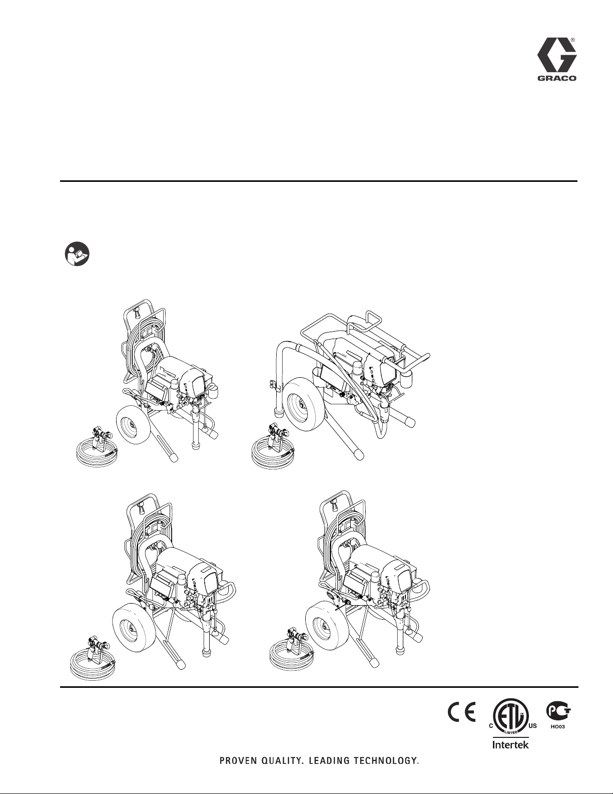
Operation
Electric Airless Sprayers
- For Portable Airless Spraying of Architectural Coatings and Paints -
3300 psi (227 bar, 22.7 MPa) Maximum Working Pressure
IMPORTANT SAFETY INSTRUCTIONS
Read all warnings and instructions in this
manual. Save these instructions.
ti14838a
ti15034a
3A0156A
ENG
695/795 Premium Hi
ti15036a
MARK V
695/795
ti15035a
1095/1595 Premium Hi
Related Manuals:
Repair 3A0157
Parts 3A0158
Gun 311861
Page 2

Models:
Models:
695 ULTRA MAX lIl
Model QuikReel Hi-Boy Lo-Boy
258719 ✓✓
258720 ✓
258722 ✓
258872 ✓
258873 ✓
258874 ✓
258876 ✓
258877 ✓✓
826124 ✓✓
826125 ✓
826127 ✓
795 ULTRA MAX III
Model QuikReel Hi-Boy Lo-Boy
258723 ✓✓
258724 ✓
258878 ✓✓
258879 ✓
258881 ✓
258882 ✓✓
826128 ✓✓
826129 ✓
1095 ULTRA MAX III
Model QuikReel Hi-Boy Lo-Boy
258727 ✓✓
258728 ✓
258883 ✓✓
258884 ✓
258886 ✓✓
826130 ✓✓
826131 ✓
1595 ULTRA MAX III
Model QuikReel Hi-Boy Lo-Boy
258763 ✓✓
258764 ✓
258765 ✓✓
258766 ✓
826132 ✓✓
826133 ✓
826134 ✓✓
826135 ✓
MARK IV
Model QuikReel Hi-Boy Lo-Boy
258729 ✓✓
MARK V
Model QuikReel Hi-Boy Lo-Boy
258730 ✓✓
258887 ✓✓
2 3A0156A
Page 3
Warnings
Warnings
The following warnings are for the setup, use, grounding, maintenance and repair of this equipment. The exclamation
point symbol alerts you to a general warning and the hazard symbol refers to procedure-specific risks. Refer back
to these warnings. Additional, product-specific warnings may be found throughout the body of this manual where applicable.
Grounding Instructions
This product must be grounded. In the event of an electrical short circuit, grounding reduces the risk of electric shock by
providing an escape wire for the electric current. This product is equipped with a cord having a grounding wire with an
appropriate grounding plug. The plug must be plugged into an outlet that is properly installed and grounded in accordance with all local codes and ordinances.
WARNING
GROUNDING
This product must be grounded. In the event of an electrical short circuit, grounding reduces the risk of electric shock by providing an escape wire for the electric current. This product is equipped with a cord having a
grounding wire with an appropriate grounding plug. The plug must be plugged into an outlet that is properly
installed and grounded in accordance with all local codes and ordinances.
• Improper installation of the grounding plug is able to result in a risk of electric shock.
• When repair or replacement of the cord or plug is required, do not connect the grounding wire to either
flat blade terminal.
• The wire with insulation having an outer surface that is green with or without yellow stripes is the ground-
ing wire.
• Check with a qualified electrician or serviceman when the grounding instructions are not completely
understood, or when in doubt as to whether the product is properly grounded.
• Do not modify the plug provided; if it does not fit the outlet, have the proper outlet installed by a qualified
electrician.
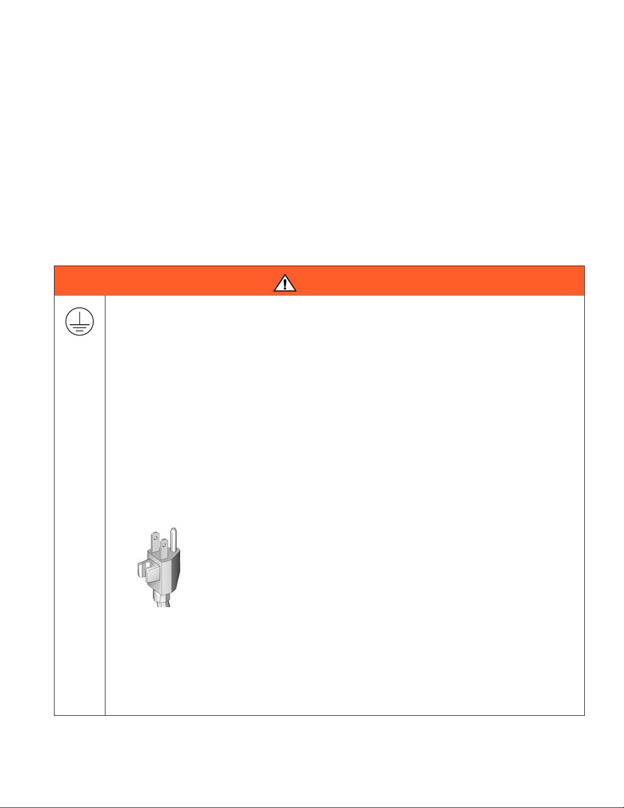
• This product is for use on a nominal 120V circuit and has a grounding plug similar to the plug illustrated
in the figure below.
• Only connect the product to an outlet having the same configuration as the plug.
• Do not use an adapter with this product.
Extension Cords:
• Use only a 3-wire extension cord that has a 3-blade grounding plug and a 3-slot receptacle that accepts
the plug on the product.
• Make sure your extension cord is not damaged. If an extension cord is necessary, use 12 AWG
2
(2.5 mm
• An undersized cord results in a drop in line voltage and loss of power and overheating.
) minimum to carry the current that the product draws.
3A0156A 3
Page 4
Warnings
WARNING
FIRE AND EXPLOSION HAZARD
Flammable fumes, such as solvent and paint fumes, in work area can ignite or explode. To help prevent fire
and explosion:
• Do not spray flammable or combustible materials near an open flame or sources of ignition such as cig-
arettes, motors, and electrical equipment.
• Paint or solvent flowing through the equipment is able to result in static electricity. Static electricity cre-
ates a risk of fire or explosion in the presence of paint or solvent fumes. All parts of the spray system,
including the pump, hose assembly, spray gun, and objects in and around the spray area shall be properly grounded to protect against static discharge and sparks. Use Graco conductive or grounded
high-pressure airless paint sprayer hoses.
• Do not clean with materials having flash points lower than 70° F (21° C). Use water-based material or
mineral spirits-type material only. For complete information about your fluid, request the MSDS from the
fluid distributor or retailer.
• Verify that all containers and collection systems are grounded to prevent static discharge.
• Connect to a grounded outlet and use grounded extensions cords. Do not use a 3-to-2 adapter.
• Do not use a paint or a solvent containing halogenated hydrocarbons.
• Keep spray area well-ventilated. Keep a good supply of fresh air moving through the area. Keep pump
assembly in a well ventilated area. Do not spray pump assembly.
• Do not smoke in the spray area.
• Do not operate light switches, engines, or similar spark producing products in the spray area.
• Keep area clean and free of paint or solvent containers, rags, and other flammable materials.
• Know the contents of the paints and solvents being sprayed. Read all Material Safety Data Sheets
(MSDS) and container labels provided with the paints and solvents. Follow the paint and solvents manufacturer’s safety instructions.
• Fire extinguisher equipment shall be present and working.
• Sprayer generates sparks. When flammable liquid is used in or near the sprayer or for flushing or clean-
ing, keep sprayer at least 20 feet (6 m) away from explosive vapors.
SKIN INJECTION HAZARD
• Do not aim the gun at, or spray any person or animal.
• Keep hands and other body parts away from the discharge. For example, do not try to stop leaks with
any part of the body.
• Always use the nozzle tip guard. Do not spray without nozzle tip guard in place.
• Use Graco nozzle tips.
• Use caution when cleaning and changing nozzle tips. in the case where the nozzle tip clogs while spray-
ing, follow the Pressure Relief Procedure for turning off the unit and relieving the pressure before
removing the nozzle tip to clean.
• Do not leave the unit energized or under pressure while unattended. When the unit is not in use, turn off
the unit and follow the Pressure Relief Procedure for turning off the unit.
• High-pressure spray is able to inject toxins into the body and cause serious bodily injury. In the event
that injection occurs, get immediate surgical treatment.
• Check hoses and parts for signs of damage. Replace any damaged hoses or parts.
• This system is capable of producing 3300 psi. Use Graco replacement parts or accessories that are
rated a minimum of 3300 psi.
• Always engage the trigger lock when not spraying. Verify the trigger lock is functioning properly.
• Verify that all connections are secure before operating the unit.
• Know how to stop the unit and bleed pressure quickly. Be thoroughly familiar with the controls.
4 3A0156A
Page 5
Warnings
WARNING
EQUIPMENT MISUSE HAZARD
Misuse can cause death or serious injury.
• Always wear appropriate gloves, eye protection, and a respirator or mask when painting.
• Do not operate or spray near children. Keep children away from equipment at all times.
• Do not overreach or stand on an unstable support. Keep effective footing and balance at all times.
• Stay alert and watch what you are doing.
• Do not leave the unit energized or under pressure while unattended. When the unit is not in use, turn off
the unit and follow the Pressure Relief Procedure for turning off the unit.
• Do not operate the unit when fatigued or under the influence of drugs or alcohol.
• Do not kink or over-bend the hose.
• Do not expose the hose to temperatures or to pressures in excess of those specified by Graco.
• Do not use the hose as a strength member to pull or lift the equipment.
ELECTRIC SHOCK HAZARD
This equipment must be grounded. Improper grounding, setup, or usage of the system can cause electric
shock.
• Turn off and disconnect power at main switch before disconnecting any cables and before servicing
equipment.
• Connect only to grounded power source.
• All electrical wiring must be done by a qualified electrician and comply with all local codes and regula-
tions.
PRESSURIZED ALUMINUM PARTS HAZARD
Use of fluids that are incompatible with aluminum in pressurized equipment can cause serious chemical
reaction and equipment rupture. Failure to follow this warning can result in death, serious injury, or property
damage.
• Do not use 1,1,1-trichloroethane, methylene chloride, other halogenated hydrocarbon solvents or fluids
containing such solvents.
• Many other fluids may contain chemicals that can react with aluminum. Contact your material supplier
for compatibility.
MOVING PARTS HAZARD
Moving parts can pinch, cut or amputate fingers and other body parts.
• Keep clear of moving parts.
• Do not operate equipment with protective guards or covers removed.
• Pressurized equipment can start without warning. Before checking, moving, or servicing equipment, fol-
low the Pressure Relief Procedure and disconnect all power sources.
PERSONAL PROTECTIVE EQUIPMENT
You must wear appropriate protective equipment when operating, servicing, or when in the operating area of
the equipment to help protect you from serious injury, including eye injury, hearing loss, inhalation of toxic
fumes, and burns. This equipment includes but is not limited to:
• Protective eyewear, and hearing protection.
• Respirators, protective clothing, and gloves as recommended by the fluid and solvent manufacturer.
3A0156A 5
Page 6
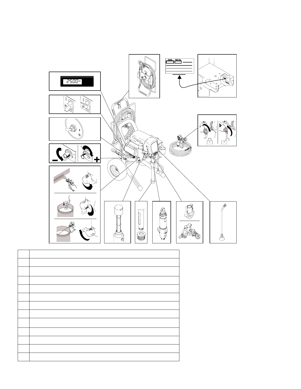
Component Identification
Component Identification
13.
1.
2.
3.
4.
5.
12.
11.
1 Premium Digital Display
2 ON/OFF Switch
3
WatchDog
™
Switch (not available on Mark V or Standard Units)
4 Pressure Control
5 Prime / Spray Valve
6 Filter
7 Siphon Tube
8Pump
9
Bearing Housing / ProConnect
10 Drain Tube
11 Trigger Lock
6. 7.
™
8.
9.
10.
ti14839a
12 Model/Serial Tag
13 Hose Reel
6 3A0156A
Page 7

Grounding
Grounding
The sprayer must be grounded. Grounding reduces the
risk of static and electric shock by providing an escape
wire for the electrical current due to static build up or in
the event of a short circuit.
The sprayer cord includes a grounding wire with an
appropriate grounding contact.
The plug must be plugged into an outlet that is properly
installed and grounded in accordance with all local
codes and ordinances.
ti2810a
Do not modify plug! Tampering with the plug will result in
a voided warranty. If plug will not fit in outlet, have
grounded outlet installed by a qualified electrician. Do
not use an adapter.
ti4297a
Pails
Solvent and oil/based fluids: follow local code. Use
only conductive metal pails, placed on a grounded surface such as concrete.
Do not place pail on a nonconductive surface such as
paper or cardboard which interrupts grounding continuity.
ti5850a
Grounding a metal pail: connect a ground wire to the
pail by clamping one end to pail and other end to a true
earth ground.
Power Requirements
• 100-120V units require 100-120 VAC, 50/60 Hz,
15A, 1 phase.
• 230V units require 230 VAC, 50/60 HZ,
10A, 1 phase.
To maintain grounding continuity when flushing or
Extension Cord
Use an extension cord with an undamaged ground contact. If an extension cord is necessary, use a 3-wire, 12
AWG (2.5 mm
Ground
120 volt plug
3A0156A 7
2
) minimum.
relieving pressure: hold metal part of spray gun firmly
to side of a grounded metal pail. Then trigger gun.
ti14840a
ti13243a
Page 8

15/20 Amp Switch (Not Available on All Units)
20
15/20 Amp Switch (Not Available on All Units)
ti14919a
Select 15A or 20A setting based on your circuit rating.
Pressure Relief Procedure
1. Turn power OFF. Wait 7 seconds for power to
dissipate.
ti4265a
2. Lock gun trigger safety. Remove guard and
SwitchTip.
3. Turn pressure to lowest setting. Trigger gun to
relieve pressure.
ti14841a
-
4. Put drain tube in pail. Turn prime valve down to
DRAIN position.
ti2595a
ti14842a
ti10166a
8 3A0156A
ti2769a
Page 9

Setup
1. Standard Units Only: Connect Graco airless hose
to sprayer. Tighten securely.
ti14843a
2. Standard Units Only: Connect other end of hose
to gun and tighten securely.
Setup
6. Fill throat packing nut with Graco TSL to prevent
premature packing wear. Do this each time you
spray.
ti13453a
7. Turn power OFF.
ti4265a
ti4265a
ti13031a
3. Engage gun trigger safety.
ti10166a
4. Remove tip guard.
ti2769a
5. Check inlet strainer for clogs and debris.
8. Plug power supply cord into a properly grounded
electrical outlet.
ti2810a
9. Turn prime valve down to DRAIN position.
ti14842a
10. Place pump in grounded metal pail partially filled
with flushing fluid. Attach ground wire to pail and
to true earth ground. Perform steps 1 - 5 of Startup
to flush out storage oil shipped in sprayer. Use water
to flush water-base paint and mineral spirits to flush
oil-base paint and storage oil.
ti14844a
3A0156A 9
Page 10

Startup
Startup
5. Hold gun against grounded metal flushing pail. Trigger gun and increase fluid pressure 1/2 turn. Flush
1minute.
1. Turn pressure control to lowest pressure.
2. Turn power ON.
ti4266a
ti4266a
3. Increase pressure 1/2 turn to start motor and allow
fluid to circulate through drain tube for 15 seconds;
turn pressure down.
1
/
2
ti4271a
6. Inspect for leaks. Do not stop leaks with hand or a
rag! If leaks occur, perform Pressure Relief Proce-
dure, page 8. Tighten fittings. Perform Startup,
steps 1 - 5. If no leaks, proceed to step 7.
7. Place pump in paint pail.
ti2714a
PAINT
ti13243a
8. Trigger gun again into flushing pail until paint
appears. Move gun to paint pail and trigger for 20
seconds. Set gun safety ON. Assemble tip and
15sec.
guard, see instructions on next page.
1/2
4. Turn prime valve forward to SPRAY position. Disengage gun trigger safety.
ti13029a
ti14845a
10 3A0156A
ti10167a
ti10166a
Page 11

Switch Tip Installation
1. Use spray tip (A) to insert OneSeal™ (B) into
guard (C).
Switch Tip Installation
Spray
1. Spray test pattern. Increase pressure to eliminate
heavy edges. Use smaller tip size if pressure adjustment can not eliminate heavy edges.
C
B
A
ti13023a
2. Insert Switch Tip.
3. Screw assembly onto gun. Tighten.
ti13030a
2. Hold gun perpendicular, 10-12 in. (25-30 cm) from
surface. Spray back and forth. Overlap by 50%. Trigger gun after moving and release before stopping.
ti13024a
ti13025a
Clearing Tip Clog
1. Release trigger, put safety ON. Rotate SwitchTip.
Take safety OFF. Trigger gun to clear clog. Never
point gun at your hand or into a rag!
ti2710a
ti10166a
ti13033a
ti10167a
2. Put safety ON. Return SwitchTip to original position.
Take safety OFF and continue spraying.
ti10166a
3A0156A 11
ti13034a
ti10167a
Page 12

WatchDog™ Protection System (Not Available on All Units)
WatchDog™ Protection
System
Pump stops automatically when material pail is empty.
To Activa te:
1. Perform Startup.
2. Premium units with digital display:
Turn WatchDog switch ON and WD ON displays.
EMPTY displays/flashes and pump stops when
Watchdog protection system detects an empty
material pail.
(Not Available on All Units)
ti7398a
Fast Flush
To flush the hose and gun at an accelerated speed, perform the following steps:
1. Perform steps 1 - 3 of Cleanup, page 16.
2. Hold gun trigger in and turn prime valve down to
DRAIN position and then over to FAST FLUSH.
ti14849a
ti6224a
3. Turn WatchDog switch OFF. Add material or reprime
sprayer. Turn pump switch OFF and ON to reset
WatchDog protection system. Turn WatchDog
switch back ON to continue to monitor material
level.
ti7399a
TIA
3. Continue flushing system until fluid appears clear.
12 3A0156A
Page 13

Hose Reel (Not Available on All Units)
3. Pull reel handle up and turn clockwise to reel in
Be sure to keep your head clear of hose reel while
winding up hose.
1. Make sure hose is routed through hose guide.
Hose Reel (Not Available on All Units)
hose.
ti13504a
2. Lift and turn pivot lock 90° to unlock hose reel. Pull
on hose to remove it from hose reel.
ti13501a
ti13503a
ti13502a
NOTE: The hose reel can be locked into two positions:
Usage (A) and Storage (B).
(A)
(B)
ti13563a
3A0156A 13
Page 14

Digital Tracking System (Not Available on All Units)
Digital Tracking System (Not Available on All Units)
Operation Main Menu
Short press to move to next display. Press and hold (5
seconds) to change units or reset data.
ti13605a
1. Turn pressure to lowest setting. Trigger gun to
relieve pressure. Turn prime valve down to DRAIN
position.
ti14842a
-
ti13243a
2. Turn power ON. Pressure display appears. Dashes
will not appear unless pressure is less than 200 psi
(14 bar, 1,4 MPa).
Job Gallons
1. Short press DTS button to move to Job Gallons (or
liters x 10).
Psi
ti13612a
ti13620a
ti13610a
NOTE: JOB scrolls past, then the number of gallons
sprayed above 1000 psi (70 bar, 7 MPa) displays.
2. Press and hold to reset to zero.
Lifetime Gallons
1. Short press DTS button to move to Lifetime Gallons
(or liters x 10).
NOTE: LIFE scrolls briefly, then the number of gallons sprayed above 1000 psi (70 bar, 7 MPa) displays.
ti4266a
psi
ti13621a
Change Display Units
Press and hold DTS button for 5 seconds to change
pressure units (psi, bar, MPa) to desired units. Selection of bar or MPa changes gallons to liters x 10. To
change display units DTS must be in pressure display
mode and pressure must be at zero.
Psi
ti13620a
Psi
bar
MPa
ti13604a
ti13601a
OR
ti13617a
ti13611a
14 3A0156A
Page 15

Secondary Menu - Stored Data and
WatchDog Pump Protection Modes
Digital Tracking System (Not Available on All Units)
1. Perform Pressure Relief, steps 1 - 4 if they have
not already been done.
2. Turn power switch on while holding DTS button
down.
ti4266a
ti13605a
3. SERIAL NUMBER scrolls past and then serial number (e.g. 00001) displays.
ti13622a
ti7362a
4. Short press DTS button and MOTOR HOURS
scrolls past and then total motor run hours are displayed.
7. Short press DTS button. W-DOG scrolls past then
OFF displays if watchdog switch is OFF. ON dis-
plays if Watchdog switch is ON.
ti13608a
ti13626a
ti13614a
8. Press and hold (8 seconds) DTS button to move to
WatchDog Trigger % menu. Continue to hold DTS
button and Watchdog can be set to trigger at 30, 40,
50, or 60% of current sprayer pressure setting.
Release DTS button when desired % is displayed.
Default is 50%.
ti13618a
ti13619a
5. Short press DTS button. LAST ERROR CODE
scrolls by and last error code is displayed; e.g. E=07
(see Repair manual).
ti13601a
ti13615a
ti13607a
6. Press and hold DTS button to clear error code to
zero.
ti13609a
ti13606a
TIA
9. Short press to move to SOFTWARE REV.
ti13613a
ti13623a
10. Short press DTS button. MOTOR ID RESISTOR
scrolls by and model code number (see below).
Code Number Models
0695
2 795 / MARK IV
4 1095 / 220V MARK V
6 1595 / 120V MARK V
3A0156A 15
Page 16

Cleanup
Cleanup
1. Perform Pressure Relief Procedure (page 8),
steps 1 - 4. Remove siphon tube set from paint and
place in flushing fluid. Remove tip guard from gun.
ti2756a
NOTE: Use water for water-base paint, mineral spirits
for oil-base paint, or other solvents recommended by
manufacturer.
5. Turn prime valve down to DRAIN position and allow
flushing fluid to circulate until flushing fluid appears
clear.
ti14842a
6. Turn prime valve forward to SPRAY position. Trigger
gun into flushing pail to purge fluid from hose.
2. Turn power ON. Turn prime valve forward to SPRAY
position.
ti4266a
ti14845a
3. Increase pressure to 1/2. Hold gun against paint
pail. Take trigger safety OFF. Trigger gun until flushing fluid appears.
1
/
2
ti4271a
ti14846a
4. Move gun to waste pail, hold gun against pail, trigger gun to thoroughly flush system. Release trigger
and put trigger safety ON.
ti14845a
ti14847a
7. Raise siphon tube above flushing fluid and run
sprayer for 15 to 30 seconds to drain fluid. Turn
power OFF
PAI NT
FLUSH
ti2820a
8. Turn prime valve down DRAIN position. Unplug
sprayer.
ti2718a
ti14842a
ti14847a
16 3A0156A
Page 17

9. Remove filters from gun and sprayer, if installed.
Clean and inspect. Install filters.
ti15018a
10. If flushing with water, flush again with mineral spirits,
or Pump Armor, to leave a protective coating to prevent freezing or corrosion.
Cleanup
ti2895a
Pump Armor
11. Wipe sprayer, hose and gun with a rag soaked in
water or mineral spirits.
ti2776a
3A0156A 17
Page 18

Technical Data
100 - 120V,
Model
695
795
Mark IV
1095
Mark V
1595
Mark V
220 - 240V,
A, Hz
14.8,
50/60
15,
50/60
15,
50/60
15,
50/60
N/A 10,
20/15,
50/60
20/15,
50/60
A, Hz
50/60
50/60
50/60
50/60
Technical Data
Generator
Minimum W
9,
10,
N/A 5000 2.2
10,
N/A 5000 2.8
N/A 5000 2.8
5000 2.0
5000 2.2
5000 2.4
5000 2.4
Motor HP
(W)
(1490)
(1640)
(1640)
(1790)
(1790)
(2090)
(2090)
Cycles per
gallon (liter)
226
(60)
195
(52)
195
(52)
123
(33)
110
(29)
110
(29)
110
(29)
Maximum Delivery
gpm (lpm)
0.95
(3.6)
1.1
(4.2)
1.1
(4.2)
1.2
(4.5)
1.3
(4.9)
1.35
(5.1)
1.35
(5.1)
Maximum
Tip Size
0.031 1/4 in.
0.033 1/4 in.
0.033 3/8 in.
0.035 1/4 in.
0.037 3/8 in.
0.039 1/4 in.
0.039 3/8 in.
Fluid
Outlet
npsm
Basic Sprayer Wetted Parts..............................
zinc- and nickel-plated carbon steel, nylon, stainless
steel, PTFE, Acetel, leather, UHMWPE, aluminum
tungsten carbide, PEEK, brass
Weight lb
Model
695
795
Mark IV
1095
1595
Mark V
94
(43)
98
(45)
N/A N/A 119
N/A 120
N/A 125
N/A 130
(kg)
94
(43)
98
(45)
(55)
(57)
(59)
111
(50)
115
(52)
(54)
141
(64)
146
(66)
151
(68)
27.5
(69.9)
27.5
(69.9)
N/A N/A 39
N/A 29.5 (74.9) Handle down,
N/A 29.5 (74.9) Handle down,
N/A 29.5 (74.9) Handle down,
Noise Level
Sound power ...............................................91 dBa*
Sound pressure .........................................82 dBa*
*per ISO 3744; measured at 3.1 feet (1 m)
Dimensions
Height in.
(cm)
28.5 (72.4) Handle down,
38.75 (98.4) Handle up
28.5 (72.4) Handle down,
38.75 (98.4) Handle up
38.5 (97.8) Handle up
38.5 (97.8) Handle up
38.5 (97.8) Handle up
39
(99)
39
(99)
(99)
39
(99)
39
(99)
39
(99)
Length in.
(cm)
Lo-Boy Hi-Boy QuikReel
37
(94)
37
(94)
N/A N/A 29.5
N/A 26
N/A 26
N/A 26
26
(66)
26
(66)
(66)
(66)
(66)
29.5
(75)
29.5
(75)
(75)
28
(71)
28
(71)
28
(71)
Width
in (cm)Lo-Boy Hi-Boy QuikReel Lo-Boy Hi-Boy QuikReel
22.5
(57.2)
22.5
(57.2)
22.5
(57.2)
24
(61)
22.5
(57.2)
24
(61)
18 3A0156A
Page 19

Notes
Notes
3A0156A 19
Page 20

Warranty
Graco warrants all equipment referenced in this document which is manufactured by Graco and bearing its name to be free from defects in
material and workmanship on the date of sale to the original purchaser for use. With the exception of any special, extended, or limited warranty
published by Graco, Graco will, for a period of twelve months from the date of sale, repair or replace any part of the equipment determined by
Graco to be defective. This warranty applies only when the equipment is installed, operated and maintained in accordance with Graco’s written
recommendations.
This warranty does not cover, and Graco shall not be liable for general wear and tear, or any malfunction, damage or wear caused by faulty
installation, misapplication, abrasion, corrosion, inadequate or improper maintenance, negligence, accident, tampering, or substitution of
non-Graco component parts. Nor shall Graco be liable for malfunction, damage or wear caused by the incompatibility of Graco equipment with
structures, accessories, equipment or materials not supplied by Graco, or the improper design, manufacture, installation, operation or
maintenance of structures, accessories, equipment or materials not supplied by Graco.
This warranty is conditioned upon the prepaid return of the equipment claimed to be defective to an authorized Graco distributor for verification of
the claimed defect. If the claimed defect is verified, Graco will repair or replace free of charge any defective parts. The equipment will be returned
to the original purchaser transportation prepaid. If inspection of the equipment does not disclose any defect in material or workmanship, repairs will
be made at a reasonable charge, which charges may include the costs of parts, labor, and transportation.
THIS WARRANTY IS EXCLUSIVE, AND IS IN LIEU OF ANY OTHER WARRANTIES, EXPRESS OR IMPLIED, INCLUDING BUT NOT LIMITED
TO WARRANTY OF MERCHANTABILITY OR WARRANTY OF FITNESS FOR A PARTICULAR PURPOSE.
Graco’s sole obligation and buyer’s sole remedy for any breach of warranty shall be as set forth above. The buyer agrees that no other remedy
(including, but not limited to, incidental or consequential damages for lost profits, lost sales, injury to person or property, or any other incidental or
consequential loss) shall be available. Any action for breach of warranty must be brought within two (2) years of the date of sale.
GRACO MAKES NO WARRANTY, AND DISCLAIMS ALL IMPLIED WARRANTIES OF MERCHANTABILITY AND FITNESS FOR A
PARTICULAR PURPOSE, IN CONNECTION WITH ACCESSORIES, EQUIPMENT, MATERIALS OR COMPONENTS SOLD BUT NOT
MANUFACTURED BY GRACO. These items sold, but not manufactured by Graco (such as electric motors, switches, hose, etc.), are subject to
the warranty, if any, of their manufacturer. Graco will provide purchaser with reasonable assistance in making any claim for breach of these
warranties.
In no event will Graco be liable for indirect, incidental, special or consequential damages resulting from Graco supplying equipment hereunder, or
the furnishing, performance, or use of any products or other goods sold hereto, whether due to a breach of contract, breach of warranty, the
negligence of Graco, or otherwise.
FOR GRACO CANADA CUSTOMERS
The Parties acknowledge that they have required that the present document, as well as all documents, notices and legal proceedings entered into,
given or instituted pursuant hereto or relating directly or indirectly hereto, be drawn up in English. Les parties reconnaissent avoir convenu que la
rédaction du présente document sera en Anglais, ainsi que tous documents, avis et procédures judiciaires exécutés, donnés ou intentés, à la suite
de ou en rapport, directement ou indirectement, avec les procédures concernées.
For the latest information about Graco products, visit www.graco.com.
TO PLACE AN ORDER, contact your Graco distributor or call 1-800-690-2894 to identify the nearest distributor.
All written and visual data contained in this document reflects the latest product information available at the time of publication.
Graco reserves the right to make changes at any time without notice.
This manual contains English. MM 3A0156
Graco Headquarters: Minneapolis
International Offices: Belgium, China, Japan, Korea
GRACO INC. P.O. BOX 1441 MINNEAPOLIS, MN 55440-1441
Copyright 2009, Graco Inc. is registered to ISO 9001
www.graco.com
2009
 Loading...