

Page 1
Instruction Manual
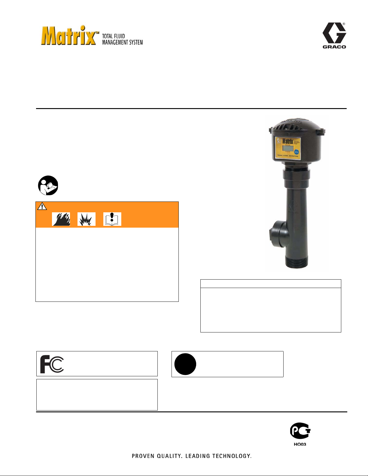
Tank Level Monitor
Part No. 119274, Series D, North America (N.A.)
Part No. 120105, Series D, (Australia)
Used to monitor tank levels for oils and anti-freeze mixtures.
The Tank Level Monitor is to be used only with Graco Matrix Software.
US Patent D484,819
Important Safety Instructions
Read all warnings and instructions in this manual.
Save these instructions.
WARNING
Not for use in hazardous locatons.
Ambient temperature range -22°F to 122°F (-30°C
to 50°C).
309500L
Do not use the Tank Level Monitor with fluids having
an auto ignition below 392° F (200° C).
Do not use the Tank Level Monitor with pressurized
tanks.
Read warnings and instructions.
The Matrix Tank Level Monitor contains an RF device with the following approvals:
FCC ID: JHIGNET
IC: 4840AGNET
Industry Canada Statement
The term “IC” before the certification/registration number only signifies that the Industry
Canada technical specifications were met.
✓
• Do not over tighten tank level monitor into
tank bung! Over tightening can cause perma-
nent damage and result in inaccurate readings.
• Do not use thread sealant or adhesive! Many
of these products are chemically incompatible
with the PC/ABS plastic.
Australian Vendor Code: N3845
CAUTION
Page 2

Notes
2 309500L
Page 3
Warnings
Warnings
The following warnings include general safety information for this equipment. More specific warnings are included in
the text where appropriate.
WARNING
FIRE AND EXPLOSION HAZARD
When flammable fluids are present in the work area, such as gasoline and windshield wiper fluid, be
aware that flammable fumes can ignite or explode. To help prevent fire and explosion:
• Use equipment only in well ventilated area.
• Eliminate all ignition sources, such as cigarettes and portable electric lamps.
• Keep work area free of debris, including rags and spilled or open containers of solvent and gasoline.
• Do not plug or unplug power cords or turn lights on or off when flammable fumes are present.
• Ground equipment.
• Use only grounded hoses.
• If there is static sparking or you feel a shock, stop operation immediately. Do not use equipment
until you identify and correct the problem.
BATTERY SAFETY
The battery may leak, explode, cause burns, or cause an explosion if mishandled:
• You must use the battery type specified for use with the equipment.
• Sparking can occur when changing batteries. Only replace the battery in a non-hazardous location,
away from flammable fluids or fumes.
• Handle and dispose of battery properly - do not short circuit, charge, force over discharge, disassemble, crush, penetrate, incinerate, or heat the battery to a temperature exceeding 185° F (85° C).
EQUIPMENT MISUSE HAZARD
Misuse can cause death or serious injury.
• Do not exceed the maximum working pressure or temperature rating of the lowest rated system
component. See Technical Data in all equipment manuals.
• Use fluids and solvents that are compatible with equipment wetted parts. See Technical Data in all
equipment manuals. Read fluid and solvent manufacturer’s warnings.
• Check equipment daily. Repair or replace worn or damaged parts immediately.
• Do not alter or modify equipment.
• For professional use only.
• Use equipment only for its intended purpose. Call your Graco distributor for information.
• Route hoses and cables away from traffic areas, sharp edges, moving parts, and hot surfaces.
• Do not use hoses to pull equipment.
• Comply with all applicable safety regulations.
309500L 3
Page 4
Installation
Installation
WARNING
Installing and servicing this equipment requires
access to parts which may cause fire, explosion, and
serious injury if work is not performed properly. Do not
install or service this equipment unless you are trained
and qualified. Read warnings, page 3.
The location of the dipswitches will change to the same
settings of the Transceiver that it must communicate
with. The factory default setting for all Tank Level Monitors is (AA) using a RS232 connection. The first A refers
to the Network ID and the second A refers to the Transceiver ID. If multiple Transceivers are used or if RS422
connection is used, the factory default settings will
require changing.
Determining what settings to use
CAUTION
• Do not over tighten tank level monitor into tank
bung! Over tightening can cause permanent dam-
age and result in inaccurate readings.
• Do not use thread sealant or adhesive! Many of
these products are chemically incompatible with the
PC/ABS plastic.
TLM Dipswitch Settings
Tank Level Monitors (TLM) and Transceivers have two, 4
- position dipswitches labeled S1 and S2.
• Network ID (S1): This is the RF identification
setting assigned to a Matrix installation. All components in the system use this same Network
ID. For example, if one dealership is using Network ID (A), the dealership across the street
would require Network ID (B) to avoid RF interference between the two systems.
• Transceiver ID (S2): This is the RF identifica-
tion setting assigned to a Matrix Transceiver(s).
Matrix system components are then assigned to
the Transceiver(s) ID's as desired for RF communication. For example, if a system required
two Transceivers, some components would be
assigned to one Transceiver and other components would be assigned to the second Transceiver using the Transceiver ID dipswitch.
There are (8) Network ID's and (8) Transceiver ID's possible by changing the position of the dipswitches. The
eight positions are identified as A, B, C, D, E, F, G, and
H.
Tank Level Monitor dipswitches must be set to match
those of the transceiver the TLM will be communicating
with.
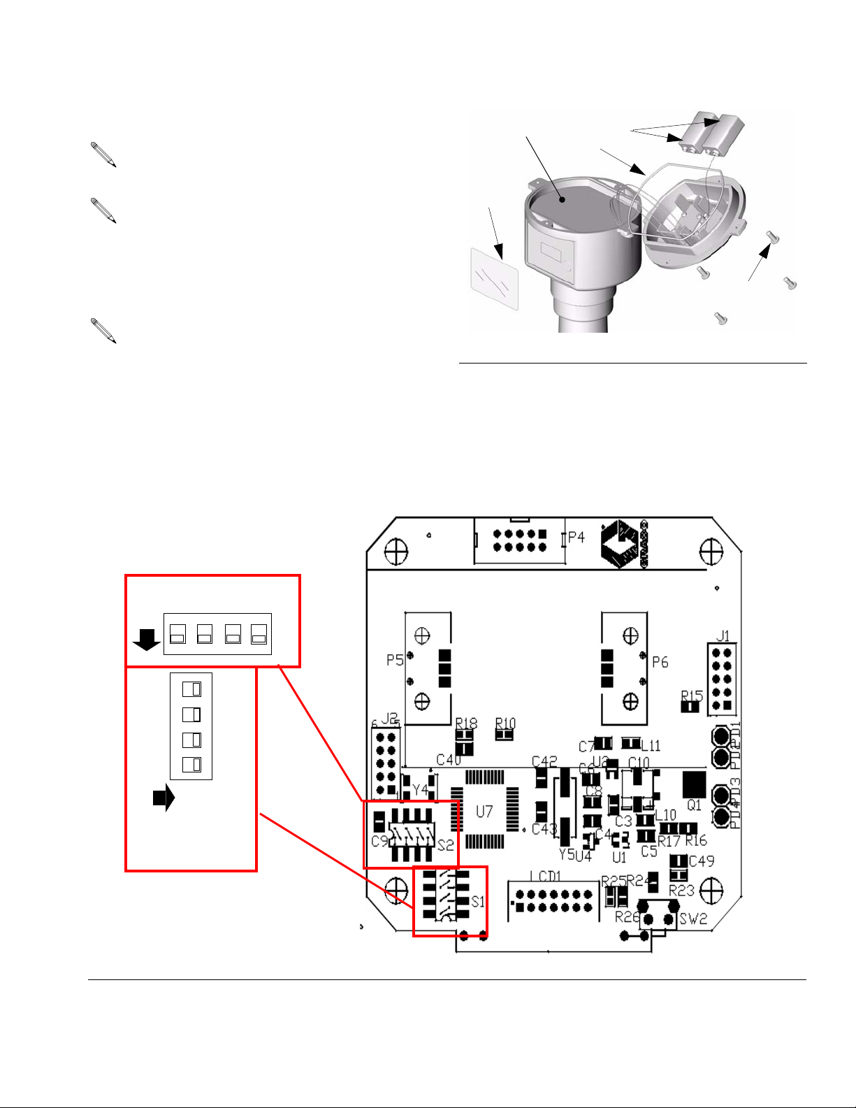
1. Remove the protective plastic cover (5) over the
Tank Level Monitor display that was used for shipping and discard. See F
2. Remove the four screws (3) holding the tank monitor
cover in place.
WARNING
Read and follow
3. Remove the cover.
4. Remove the insulating foam (4) to access the circuit
board.
5. Set the S1 and S2 settings to match those of the
transceiver that this TLM will communicate with.
Wait at least 30 seconds after the dipswitch settings
are made before installing the batteries. If you do
not wait the 30 seconds, the software will not recognize the new settings.
6. Install the (2) alkaline 9-volt batteries (1) provided.
Be sure that the batteries fully engage the mounting
clips by pushing on the bottom of the batteries with
your thumbs.
On initial power up of the TLM, it will take about 30
seconds for the monitor to display information after
pressing the blue display button. This time will
decrease thereafter to a few seconds
BATTERY SAFETY
IG. 1.
warnings, page 3.
4 309500L
Page 5
7. Replace the insulating foam (4) and reconnect the
batteries.
Make sure the o-ring (2) is not damaged and is in
the correct location.
Make sure the RF antenna wire (black formed wire
near the center of the top PC board) is not flattened against the PC board. This can result in poor
RF communication.
8. Replace cover and secure it with the four screws (3).
Installation
4
1
2
5
3
Make sure the cover screws are tightened securely
(18-22 in-lb) to avoid water leakage into the TLM
electronics. If a torque wrench is not used, verify
there are no gaps under the screw heads and no
gaps under the cover flange. This will ensure
proper compression of the o-ring for a water-tight
seal.
All dipswitches in down
or off position.
on
S2
12
4
3
2
4
3
F
IG. 1
n
1
o
S1
All dipswitches
to right or off
position.
F
IG. 2
309500L 5
Page 6
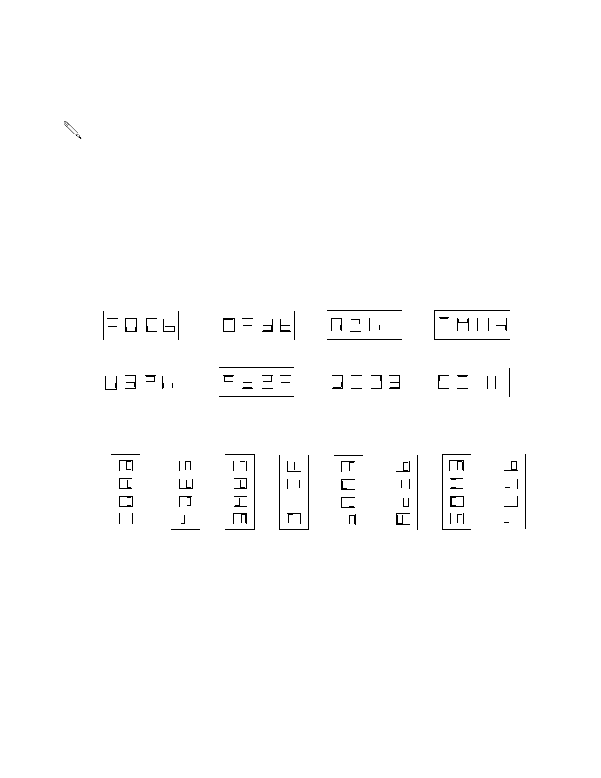
Dipswitch Setting using RS232 Connection
Dipswitch Setting using RS232 Connection
See FIG. 3 for dipswitch settings.
b
All dipswitch settings must be made without power
to the TLM (no batteries) or the settings will not be
properly communicated to the PC software.
RS232 Cable Settings
S2 Tank Level Monitor ID
F
IG. 3
A - default
on
12
3
E
on
12
3
A - default
4
3
2
1
on
S1
S2
S2
C
on
12
G
on
12
4
3
4
3
B
on
S2
4
12
4
3
F
on
S2
4
12
4
3
S2
S2
D
on
12
H
on
12
S2
4
3
S2
4
3
S1 Network ID
B
C
4
3
2
n
1
o
S1
n
o
S1
D
4
3
2
1
on
S1
E
4
3
2
1
n
o
S1
F
4
3
2
1
n
o
S1
G
4
3
2
1
n
o
S1
H
4
3
2
1
4
3
2
n
1
o
S1
6 309500L
Page 7

Dipswitch Setting using RS422 Connection:
Dipswitch Setting using RS422 Connection:
See FIG. 4 for dipswitch settings.
All dipswitch settings must be made without power
to the TLM's or the settings will not be properly
communicated to the PC software.
RS422 Cable Settings
S2 Tank Level Monitor ID
4
B
on
12
F
on
12
C
S2
4
3
S2
4
3
S1 Network ID
D
4
A
on
12
E
on
12
A
S2
4
3
S2
4
3
B
4
4
Dipswitch setting (4) of the S1 Network ID changes
position when using RS422 cable instead of
RS232 cable.
S2
S2
4
D
on
12
H
on
12
G
S2
4
3
S2
4
3
H
4
C
on
12
G
on
12
E
4
3
4
3
F
4
4
F
IG. 4
3
2
n
1
o
S1
3
2
n
1
o
S1
3
2
1
on
S1
3
2
n
1
o
S1
3
2
n
1
o
S1
3
2
n
1
o
S1
3
2
n
1
o
S1
3
2
n
1
o
S1
309500L 7
Page 8

Dipswitch Setting using RS422 Connection:
Programming Tank Level
Monitors
Graco recommends that tank monitors be programmed
prior to installation.
The PC software allows a 5 minute period to program a Tank Level Monitor
To program the tank monitors:
• Load the Matrix software to the PC and set the
Transceiver(s) dipswitches. Connect the Transceiver(s) to the PC using either RS232 or RS422
cable then supply power to the Transceiver.
• The Matrix Tank Level Monitoring PC software must
be at the Tank Monitor Setup screen and in program
mode.
1. At the Matrix Setup screen on the PC, enter all the
desired tank parameters and settings.
2. After parameters are set, program each TLM in the
system one at a time by clicking on the “Program”
action on the Matrix Setup screen.
display “Complete”. A pop-up window will appear on
the PC screen indicating the TLM is programmed.
See F
IG. 5. Label the tank name and fluid name on
the TLM. Repeat this procedure for each TLM in the
system.
4. Press the blue TLM button (A) to reset the internal
clock. If not done, the TLM will not read and report
at the scheduled time(s). When the batteries require
changing, it is not necessary to re-program the
TLM, but the blue button (A) should be pushed to
reset the internal TLM clock. If not done, the TLM
will not report at the correct scheduled times. See
Instruction Manual 309501 PC Software Guide or
Manual 309504 Tank Level Monitor Software Guide
for details.
B
3. Hold down the blue button (A) until the display (B)
reads “Program Mode.” After 5 seconds the TLM will
F
IG. 5
A
8 309500L
Page 9

Dipswitch Setting using RS422 Connection:
Installing Tank Level Monitor
CAUTION
• Do not over tighten tank level monitor into tank
bung! Over tightening can cause permanent dam-
age and result in inaccurate readings.
• Do not use thread sealant or adhesive! Many of
these products are chemically incompatible with the
PC/ABS plastic.
1. Remove the 2 in. bung fitting and screw in the TLM
hand-tight. DO NOT use a wrench to tighten as this
may damage the TLM. Do not use thread lock adhesive as this may damage the TLM.
2. The TLM must be mounted within 2 degrees of the
surface of the fluid. A level that measures degrees
should be used. Place the level on the top of the
pipe fitting on the tank. If outside the 2 degree specification, the fitting should be changed. Graco recommends that the height of the tank fitting should
not exceed 1/2 in. (1.27 cm). The fitting height can
be up to 2 in. (5.08 cm), provided the fitting is within
2 degrees of the surface of the fluid. Also, the taller
the tank, the more critical the 2 degree specification
becomes. See F
IG. 6.
CAUTION
Do not install the TLM in the tank’s fill port. Repeated
removal of the TLM will damage the unit and void the
warranty.
Port (D) is not to be used as a fill hole for oil deliveries.
See F
IG. 7.
The tank’s breather port might be the only available
location for mounting the TLM. The horizontal 2 in. npt
port (D) can be used to accommodate the breather. The
breather should be mounted in an upright position using
a 90° elbow fitting.
Do not use the horizontal port for routing pressure
relief return tubes. This can result in inaccurate
readings.
D
CAUTION
The TLM will not operate correctly if tilted more than 2°
from the surface of the tank liquid.
The TLM will not read properly when the fluid in the tank
is agitated (i.e. filling a tank with oil or anti-freeze). Be
sure to take all TLM readings when the fluid in the tank
is calm.
TLM must be mounted within 2° from perpendicular to
the surface of the fluid.
2°
F
2°
IG. 6
F
IG. 7
TI4794A
309500L 9
Page 10

Operation
Operation
Tank Level Data
The tank level monitor is equipped with an LCD display
screen (B) and a display button (A). See
The LCD display is used to view tank data. It displays:
Battery Life - the remaining life of the unit’s batteries.
Batteries should be replaced before the power remaining drops below 10%.
FIG. 9
.
Battery
100%
Nw ID - A
Tx ID - A
Version
XX.XX.XXX
First Display
Second Display
Third Display
Battery life is dependent on the number of readings
taken per day.
Network ID and Transceiver ID - displays the Network
and Transceiver ID information for 2 seconds. This ID
information relates to the dipswitch settings on the PC
board of the TLM.
Firmware - TLM version displays current firmware revision.
Fluid Level - remaining inches or cm of fluid in the tank.
Fluid Volume - the volume of fluid remaining in the tank,
based on the tank geometry defined during setup. The
TLM can be programmed to display in either gallons or
liters during programming of the TLM.
Vertical tanks use this capacity figure to calculate
tank volume. Obround and cylindrical tanks use the
tank dimensions to calculate tank volume.
No RF Signal - displays when the tank level monitor is
not receiving an RF signal from the PC transceiver. If
the tank monitor is receiving a signal or the signal is
re-established, this screen will not appear. If “No RF Signal” appears, the fluid volume and battery life data is not
being transmitted or updated at the PC. This may take
up to 15 seconds to display.
36”
Fourth Display
Fluid
100
Gallons
No RF
Signal
F
IG. 8: Example Display
After tank re-fill from an oil distributor or waste oil
tank is emptied from a waste oil service provider,
press the blue button on the TLM to ensure the
TLM will maintain the most current tank volume
status. If button is not pushed, the TLM will automatically read correctly at the next scheduled
tank reading.
Daylight Saving Time (DST) Change
The PC software automatically changes the PC time
when daylight saving time changes occur (Spring and
Fall).
When this happens the Matrix software displays a
pop-up screen instructing the administrator to re-boot
the Matrix PC. This changes the Matrix clock to match
the PC clock.
Fifth Display
(can program for liters)
Screen display when
no RF signal is
received after 10-12
seconds
The first TLM reading will be 1 hour earlier or later
(depending on the Spring or Fall daylight saving
time change), but all subsequent TLM reading will
be accurate.
10 309500L
Page 11

Viewing Data
Press and release the blue display button (A). See FIG.
9. Displays appear (B), each lasting a few seconds
before going on to the next screen. See F
Tank Level data can be viewed remotely at the PC,
using the Matrix software. See Instruction Manual
309501 PC Software Guide or Manual 309504
Tank Level Monitor Software Guide for details.
IG. 9.
Viewing Data
B
A
F
IG. 9
If the TLM reading is outside of the programmed size
parameters, the LCD display will show “Invalid Reading.”
See F
IG. 10.
F
IG. 10
Invalid
Reading
309500L 11
Page 12

Troubleshooting
Troubleshooting
Problem Cause Solution
Brand new monitor’s display is very dim.
Monitor displays “Invalid
Reading”.
Monitor will not program. Incorrect COM port selected for
Monitor has intermittent
RF communication
Unit is shipped with protective coating over display.
The TLM reading is outside of the
programmed size parameters.
transceiver.
Transceiver is not powered-up. Verify transceiver is powered-up
Attempt to program while red lights
on transceiver are lit.
Transceiver dipswitches not set cor-
rectly.
PC is not in program mode. Ensure PC is in program mode.
PC program window has expired. The PC software allows a 5-minute period to program a TLM.
TLM dipswitches settings do not
match transceiver settings.
Out of RF range.
RF obstruction.
Weak or dead batteries. Replace batteries. See Determining what settings to use,
Microprocessor not completely shut
down before installing new batteries.
RF antenna is flattened or out of
position inside the TLM.
Out of RF range.
RF obstruction.
Two TLMs are programmed to the
same address.
Weak or dead batteries. Replace batteries. See Determining what settings to use,
Remove protective coating.
Verify the programmed parameters and re-program the TLM if
necessary.
Ensure correct COM port is selected.
Wait until red lights on transceiver go blank before attempting
to program.
Ensure transceiver dipswitches are set for appropriate communication cable.
Verify settings with Transceiver (see page. 6 for dipswitch setting instructions).
Reposition Transceiver until TLM has good RF communication.
page 4.
After you have removed old batteries, wait 30 seconds to
ensure the microprocessor has completely shut down, before
installing new batteries.
Position antenna wire to suspend above the circuit board. See
7, page 5.
Reposition Transceiver until TLM has good RF communication.
Verify that each TLM is correctly programmed to a unique
address.
page 4.
12 309500L
Page 13

Problem Cause Solution
Monitor is not reporting
scheduled readings.
Monitor will not take reading when blue button is
pressed.
Monitor readings are
inaccurate.
Troubleshooting
Out of RF range.
RF obstruction.
Two TLMs are programmed to the
same address.
Weak or dead batteries. Replace batteries. See Determining what settings to use,
Microprocessor not completely shut
down before installing new batteries.
Tank Level Monitor was not programmed after scheduled times
were entered into software.
Reading is scheduled when pump is
operating.
Clock was changed on PC but the
monitor was not reprogrammed.
Weak or dead batteries. Replace batteries. See Determining what settings to use,
Batteries are not correctly seated. Ensure the batteries fully engage the mounting clips by push-
Microprocessor not completely shut
down before installing new batteries.
Monitor display is cracked. Replace monitor display.
Tank geometry incorrectly defined. See Instruction Manual 309504 Tank Level Monitor Software
Tank Level Monitor has not been
reprogrammed with latest adjustments made within Tank Setup
screen of the software.
Two TLMs are programmed to the
same address.
Fluid surface is moving while reading
is being taken.
Pipe adapters installed in the tank
bung.
Tank Level Monitor is not perpendicular to top of fluid.
Inside tank obstruction. Install in different tank bung to avoid tank obstruction.
Reposition Transceiver until TLM has good RF communication.
Verify that each TLM is correctly programmed to a unique
address.
page 4.
After you have removed old batteries, wait 30 seconds to
ensure the microprocessor has completely shut down, before
installing new batteries.
Reprogram Tank Level Monitor.
Ensure readings are scheduled at times that the pump is not
operating.
The monitor’s internal clock is synchronized with the PC clock
upon programming. Manipulating the scheduled reporting time
by changing the PC clock will cause a false indication that the
monitor is not reporting at the scheduled reporting times.
page 4.
ing on the bottom of each battery with your thumbs.
After you have removed old batteries, wait 30 seconds to
ensure the microprocessor has completely shut down, before
installing new batteries.
Guide or manual 309501 PC Software Guide for details.
Reprogram Tank Level Monitor.
Verify that each TLM is correctly programmed to a unique
address.
Ensure pump is not operating and that nothing is disturbing the
surface of the fluid during readings.
Ensure there are no adapters installed in the tank bung.
Level tank so that it is perpendicular to top of the fluid and/or
realign Tank Level Monitor.
309500L 13
Page 14

Service
Service
Once the Tank Level Monitor has been installed, no
additional maintenance or service is necessary, with the
exception of replacing batteries.
Replacing Batteries
When the tank sensor or PC battery indicator shows
that replacement of batteries is needed (before power
drops below 10%), replace the TLM batteries as follows:
1. Remove the four tank monitor cover screws.
2. Replace the batteries using alkaline 9v batteries. Be
sure the batteries fully engage the mounting clips by
pushing on the bottom of the batteries with your
thumbs.
3. Replace the cover and tighten the four cover
screws.
14 309500L
Page 15

Parts
119274 (N.A.), Tank Level Monitor
120105 (Australia), Tank Level Monitor
2
4
2
Parts
1
1
1
Remove protective cover used for shipping before programming.
2
Do not remove. This is required to maintain intrinsic safety approval.
Ref.
Part No. Description Qty
No.
1 BATTERY, 9V (purchase locally) 2
2 112343 O-RING 1
3 117467 SCREW, self tapping, HI-LO,
#10-16 x 9/16
4 117743 FOAM, insulator 1
3
4
309500L 15
Page 16

Technical Data
Technical Data
Ultrasonic Tank Depth Measurement range 0 - 30 ft. (0 - 9 m) Not for use in pressurized tanks.
Fluid Level Measurement Accuracy +/- 0.5%
Mounting Standard 2 in. (npt) bung.
Height above tank for TLM and tube mount-
ing
TLM Mounting Tube and Tank Vent Graco recommends venting the tank separately from the TLM. If not
Weight (with batteries installed) 2.34lb. (1.06 g)
Operating Temperature Range -22° F to 185° F (- 30° C to 85° C) Note: Display will not function
RF Operating Temperature Range -40°F to 185°F (-40°C to 85°C)
Storage Temperature Range -40°F to 185°F (-40°C to 85°C)
Batteries Two 9V alkaline
Battery Life 1.5 years
Enclosure IP65
Intrinsic Safety Instrinsically safe Exia for use in Class I, Division 1, Group D Haz-
15 in. (30.48 cm).
possible, the TLM mounting and vent function can be combined if
required for tanks with one hole in tank.
below 32°F (0°C).
ardous Locations when used with (2) 9-volt alkaline batteries.
• Ambient temperature range -22°F to 122°F (-30°C to 50°C).
• Temperature Code: T3.
The Matrix TLM is not to be used with materials with an auto
ignition below 392°F (200°C).
RF Communication 902-928 MHz frequency hopping, spread-spectrum (N.A.).
Totally Unobstructed RF Communication
Range (based on TLM and Transceiver
mounting and RF environment)
Unobstructed RF Communication Range
(based on building construction and RF environment)
Obstructed RF Communication Range
(based on building construction and RF environment)
Tank Geometry Vertical walled tanks, cylindrical tanks, and obround tanks.
915-928 MHz frequency hopping, spread-spectrum (Australia).
1/4 mile / 1320 ft (.4 km / 402.3 m)
300-500ft (91.0-152.0)
250-300ft (76.2-91.0 m)
•Vertical Tanks
Maximum Volume 999,999 gallons or liters
Maximum Height 30ft. (360 in.)
•Cylindrical Tanks
Maximum Volume 999,999 gallons or liters
Maximum Diameter 30ft. (360 in.)
Maximum Length Unlimited
16 309500L
Page 17

Dimensions
Dimensions
A 9.1 in (231 mm)
B 4.9 in. (124 mm)
B
A
1-1/2 in. npt
2 in. npt
TI4631A
309500L 17
Page 18

Graco Standard Warranty
Graco warrants all equipment manufactured by Graco and bearing its name to be free from defects in material and workmanship
on the date of sale to the original purchaser for use. With the exception of any special, extended, or limited warranty published by
Graco, Graco will, for a period of twenty-four months from the date of sale, repair or replace any part of the equipment determined
by Graco to be defective. This warranty applies only when the equipment is installed, operated and maintained in accordance with
Graco's written recommendations.
This warranty does not cover, and Graco shall not be liable for general wear and tear, or any malfunction, damage or wear caused
by faulty installation, misapplication, abrasion, corrosion, inadequate or improper maintenance, negligence, accident, tampering,
or substitution of non-Graco component parts. Nor shall Graco be liable for malfunction, damage or wear caused by the
incompatibility of Graco equipment with structures, accessories, equipment or materials not supplied by Graco, or the improper
design, manufacture, installation, operation or maintenance of structures, accessories, equipment or materials not supplied by
Graco.
This warranty is conditioned upon the prepaid return of the equipment claimed to be defective to an authorized Graco distributor
for verification of the claimed defect. If the claimed defect is verified, Graco will repair or replace free of charge any defective parts.
The equipment will be returned to the original purchaser transportation prepaid. If inspection of the equipment does not disclose
any defect in material or workmanship, repairs will be made at a reasonable charge, which charges may include the costs of parts,
labor, and transportation.
THIS WARRANTY IS EXCLUSIVE, AND IS IN LIEU OF ANY OTHER WARRANTIES, EXPRESS OR IMPLIED, INCLUDING BUT
NOT LIMITED TO WARRANTY OF MERCHANTABILITY OR WARRANTY OF FITNESS FOR A PARTICULAR PURPOSE.
Graco's sole obligation and buyer's sole remedy for any breach of warranty shall be as set forth above. The buyer agrees that no
other remedy (including, but not limited to, incidental or consequential damages for lost profits, lost sales, injury to person or
property, or any other incidental or consequential loss) shall be available. Any action for breach of warranty must be brought within
two (2) years of the date of sale Graco makes no warranty, and disclaims all implied warranties of merchantability and fitness for a
particular purpose in connection with accessories, equipment, materials or components sold but not manufactured by Graco.
These items sold, but not manufactured by Graco (such as electric motors, switches, hose, etc.), are subject to the warranty, if any,
of their manufacturer. Graco will provide purchaser with reasonable assistance in making any claim for breach of these warranties.
In no event will Graco be liable for indirect, incidental, special or consequential damages resulting from Graco supplying
equipment hereunder, or the furnishing, performance, or use of any products or other goods sold hereto, whether due to a breach
of contract, breach of warranty, the negligence of Graco, or otherwise.
FOR GRACO CANADA CUSTOMERS
The parties acknowledge that they have required that the present document, as well as all documents, notices and legal
proceedings entered into, given or instituted pursuant hereto or relating directly or indirectly hereto, be drawn up in English. Les
parties reconnaissent avoir convenu que la rédaction du présente document sera en Anglais, ainsi que tous documents, avis et
procédures judiciaires exécutés, donnés ou intentés à la suite de ou en rapport, directement ou indirectement, avec les
procedures concernées.
Graco Phone Numbers
TO PLACE AN ORDER, contact your Graco distributor or call to identify the nearest distributor.
Phone: 612-623-6928 or Toll Free: 1-800-533-9655, Fax: 612-378-3590
All written and visual data contained in this document reflects the latest product information available at the time of publication.
Graco reserves the right to make changes at any time without notice.
This manual contains English. MM 309500
Graco Headquarters: Minneapolis
International Offices: Belgium, China, Japan, Korea
GRACO INC. P.O. BOX 1441 MINNEAPOLIS, MN 55440-1441
Copyright 2003, Graco Inc. is registered to I.S. EN ISO 9001
www.graco.com
Revised 11/2008
 Loading...