


VIC

INSTRUCTION MANUAL
IOMGWVICR01-EN
MODEL VIC
VERTICAL INDUSTRIAL TURBINE CAN PUMPS
INSTALLATION, OPERATION AND MAINTENANCE INSTRUCTIONS

Foreword
Foreword
This manual provides instructions for the Installation, Operation, and Maintenance of the Goulds Water
Technology Vertical Industrial Turbine Type Can Pumps. This manual covers a standard product. For special
options, supplemental instructions are available. This manual must be read and understood before
installation and start-up.
This instruction manual covers several different pump models. Most assembly, disassembly, and inspection
procedures are the same for all the pumps. However, where there are differences, these differences will be noted
within the manual. The design, materials, and workmanship incorporated in the construction of the Goulds Water
Technology VIC pumps makes them capable of giving long, trouble-free service. The life and satisfactory service
of any mechanical unit, however, is enhanced and extended by correct application, proper installation, periodic
inspection, condition monitoring and careful maintenance. This instruction manual was prepared to assist
operators in understanding the construction and the correct methods of installing, operating, and maintaining
these pumps.
The information contained in this book is intended to assist operating personnel by providing information on the
characteristics of the purchased equipment. It does not relieve the user of their responsibility of using accepted
engineering practices in the installation, operation, and maintenance of this equipment.
Goulds Water Technology pumps shall not be liable for physical injury, damage, or delays caused by
failure to observe the instructions for installation, operation, and maintenance contained in this manual.
Warranty is valid only when genuine Goulds Water Technology pumps parts are used.
Use of the equipment on a service other than stated in the order will nullify the warranty, unless written approval
is obtained in advance from Goulds Pumps.
For information or questions not covered in this manual, contact Goulds Water Technology at (806) 743-5700.
THIS MANUAL EXPLAINS :
• Proper Installation • Pump Overhaul
• Start-up Procedures • Trouble Shooting
• Operation Procedures • Ordering Spare or Repair Parts
• Routine Maintenance
Owner’s Information
Pump Model Number:
Pump Serial Number:
Motor Model Number:
Motor Serial Number:
Dealer:
Dealer Telephone:
Purchase Date:
Installation Date:
2

Table of Contents
SUBJECT PAGE
SECTION 1 – Safety ................................................................................................................................................... 4
SECTION 2 – General Information ............................................................................................................................. 4
Introduction .............................................................................................................................................................. 4
Receiving and Checking ............................................................................................................................................4
Materials and Equipment Required ...........................................................................................................................5
Storage ...................................................................................................................................................................... 5
General Description .................................................................................................................................................. 6
SECTION 3 – Installation ........................................................................................................................................... 9
Foundation / Piping ...................................................................................................................................................9
Pump Installation .................................................................................................................................................... 10
Installing the Bowl Assembly ................................................................................................................................... 10
Installing the Column .............................................................................................................................................. 11
Installing the Discharge Head .................................................................................................................................. 12
Installing the Stuffing Box........................................................................................................................................12
Installing the Mechanical Seal .................................................................................................................................. 13
Installing the Driver ................................................................................................................................................ 14
Installing the Thrust Pot ..........................................................................................................................................14
SECTION 4 – Pump Start Up and Operation ............................................................................................................ 20
SECTION 5 – Maintenance ...................................................................................................................................... 21
Preventive Maintenance Schedule ............................................................................................................................ 21
Packing Adjustment and Replacement ...................................................................................................................... 21
Thrust Pot Lubrication and Maintenance ................................................................................................................. 22
Seasonal Shutdown .................................................................................................................................................. 22
Recommended Lubricants .......................................................................................................................................23
Troubleshooting ......................................................................................................................................................24
SECTION 6 – Disassembly and Reassembly ..............................................................................................................26
Disassembly ............................................................................................................................................................. 26
Inspection and Reassemble ......................................................................................................................................27
SECTION 7 – Repair Parts ........................................................................................................................................29
Limited Warranty ......................................................................................................................................................30
3

Safety Instructions – SECTION 1
DANGER
WARNING
CAUTION
WARNING
Hazardous voltage
can shock, burn or
cause death.
WARNING
CAUTION
WARNING
CAUTION
TO AVOID SERIOUS OR FATAL PERSONAL
INJURY OR MAJOR PROPERTY DAMAGE, READ
AND FOLLOW ALL SAFETY INSTRUCTIONS IN
THE MANUAL AND ON THE PUMP.
This is a SAFETY ALERT SYMBOL.
When you see this symbol on the pump or
in the manual, look for one of the following signal words and be alert to the potential for personal injury or property damage.
Warns of hazards that WILL cause serious
personal injury, death or major property
damage.
Warns of hazards that CAN cause serious
personal injury, death or major property
damage.
Warns of hazards that CAN cause personal
injury or property damage.
If equipment is to be installed in a potentially explosive atmosphere and these procedures are not
followed, personal injury or equipment damage
from an explosion may result.
NOTICE: INDICATES SPECIAL INSTRUCTIONS
WHICH ARE VERY IMPORTANT AND MUST BE
FOLLOWED.
THIS MANUAL IS INTENDED TO ASSIST IN
THE INSTALLATION AND OPERATION OF
THIS UNIT. THOROUGHLY REVIEW ALL
INSTRUCTIONS AND WARNINGS PRIOR TO
PERFORMING ANY WORK ON THIS PUMP.
MAINTAIN ALL SAFETY DECALS.
Install, ground and wire according
to local and National Electrical Code
Requirements.
Install an all leg disconnect switch
near the pump.
Disconnect and lockout electrical
power before installing or servicing
the pump.
Electrical supply must match motor’s
nameplate specifications. Incorrect
voltage can cause fire, damage motor
and void the warranty.
Single phase pump motors are equipped with an
automatic thermal protector, which opens the motor’s
electrical circuit when an overload condition exists.
This can cause the pump to start unexpectedly.
General Precautions
Personal injuries will result if procedures
outlined in this manual are not followed
can cause fire, damage to motor and voids warranty.
Safety Apparel:
• Insulated work gloves when handling hot sand collar.
• Heavy work gloves when handling parts with sharp
4
Electric supply MUST match pump’s
nameplate specifications. Incorrect voltage
edges, especially impellers.
• Safety glasses (with side shields) for eye protection.
• Steel-toed shoes for foot protection when handling
parts, heavy tools, etc.
• Other personal protective equipment to protect against
hazardous/toxic fluid.
Maintenance Safety:
• Always lock out power prior to any procedure.
• Ensure pump is isolated from system and the pressure
is relieved before disassembling the pump, removing
plugs, or disconnecting the piping.
• Use proper lifting and supporting equipment to prevent
serious injury or death.
• Observe all decontamination procedures.
General Information – SECTION 2
INTRODUCTION
NOTE: The information in this manual intends to be
used as a guide only. If you are in doubt, consult
your Goulds Water Technology representative
for specific information about your pump.
The design, material, and workmanship incorporated
in the construction of Goulds Water Technology VIC
pumps makes them capable of giving long, trouble
free service. The life and satisfactory service of any
mechanical unit, however, is enhanced and extended
by correct application, proper installation, periodic
inspection and careful maintenance. This instruction
manual was prepared to assist operators in understanding
the construction and the correct methods of installing,
operating and maintaining these pumps.
Rotating components of the pump
assembly must be covered with a suitable
rigid guard to prevent injury to personnel.
Improper impeller adjustment could cause
contact between the rotating and stationary
parts, resulting in a spark and heat generation.
Study thoroughly Sections 1 through 6 and carefully
follow the instructions for installing and operating.
Section 5 contains answers to troubleshooting and
maintenance questions. Keep this instruction manual
handy for reference.
Goulds Water Technology will not be
liable for any damages or delay caused by
failure to comply with the provisions of this instruction
manual.
RECEIVING AND CHECKING
The pump should be carefully supported prior to
unloading from the carrier. Handle all components
carefully. Inspection for damage of the shipping crate
should be made prior to unpacking the pump. After
unpacking, visually inspect the pump and check the
following:
1. Contents of the pump assembly against the
packing list.
2. All components against damage.

3. All shafting for damage, should the crate be
broken or show careless handling. All shafting
must be checked for straightness.
Any shortages or damages should be immediately called
to the attention of the local freight agent of the carrier by
which the shipment arrived and proper notation made on
the bill. This will prevent any controversy when a claim is
made and facilitate prompt and satisfactory adjustment.
MATERIALS AND EQUIPMENT REQUIRED
The material and equipment necessary for installation
of the pump will vary with the size of the pump and the
type of installation.
The following list of standard tools and supplies is
offered only as a guide.
BULK MATERIAL
• Anti-Galling lubricant
(such as Dow Corning “MOLYKOTE”)
• Thread Compound
• Lubrication Oil
• Turbine Oil
• Grease
RIGGING EQUIPMENT
• Mobile power hoist, traveling crane or derrick.
• Drag line and blocks.
• Lifting Bail for Threaded Column.
• Elevator clamps, if unit is unassembled.
• Clevises – for use with eyebolts.
• Timbers – size, length and quantity to support long
pump parts on the floor.
• I-Beams or timbers to support pump over
installation.
HAND TOOLS
• Pipe wrenches
• Feeler gauges
• Machinist Level
• Set of mechanics tools including: files, wire brush,
pliers, wire cutters and pocket knife.
• Clean rags
• Dial indicator to assist in motor and pump
alignment.
OPTIONAL TOOLS TO FACILITATE PUMP
ASSEMBLY AND DISASSEMBLY
• Taperlock driver to assist in bowl assembly and
disassembly for pumps with taper lock impellers
only.
STORAGE
Goulds Water Technology carefully preserves and
protects its products for shipment. However, the
effective life of the preservatives applied at the factory
can vary from 3 to 18 months depending on the severity
of the environment in which the equipment is stored.
This section provides procedures for preparation prior to
storage and maintenance during storage of Goulds Water
Technology pumps. These procedures are necessary
to protect the precision parts of the pumps. Specific
procedures for storing motors, gear-drivers, and engines,
should be obtained from the equipment manufacturer.
This section is intended to be of general assistance to
users of Goulds Water Technology VIC pumps. It shall
not modify, amend and/or otherwise alter the scope
of Goulds Water Technology VIC pumps warranty
responsibilities to the purchaser in any way whatsoever.
Storage Preparation
Goulds Water Technology VIC pumps require proper
preparation for storage and, regular maintenance during
storage. The pump shall be considered in storage when
it has been delivered to the job site and is awaiting
installation.
Preferably, the storage area shall be paved, well drained
and free from flooding, and be indoors whenever
possible.
Weatherproof coverings used for outdoor storage shall be
flame resistant type sheeting or tarpaulins. They shall be
placed so as to provide good drainage and air circulation
and shall be tied down to protect from wind damage.
Storage area shall be maintained in a clean condition at
all times.
Pumps and/or component parts shall be placed on skids,
pallets, or shoring to permit good air circulation.
Pumps and/or component parts shall be sorted so as to
permit ready access for inspection and/or maintenance
without excessive handling.
Pumps and/or component parts stacked during storage
shall be arranged so that the racks, containers, or crates
bear full weight without distortion of pumps or parts.
Identification markings must be readily visible. Any
cover removed for internal access shall be replaced
immediately.
Pump and bowl assembly shafting shall be rotated
counter clockwise, as a minimum, once a month. Shaft
shall not be left in the same previous position, nor in the
extreme raised or lowered lateral position. Shaft should
rotate freely.
NOTE: For further information on these procedures
contact your Goulds Water Technology
representative.
Recommended Storage Procedures
Controlled storage facilities should be maintained at an
even temperature 10º F (6º C) or more above the dew
point with relative humidity less than 50% and little or
no dust. (If these requirements can not be met the pump
is to be considered in uncontrolled storage.)
For uncontrolled storage periods of 6 months or less,
the pump is to be inspected periodically to insure that all
preservatives are intact.
All pipe threads and flanged pipe covers are to be sealed
with tape.
The pump must not be stored closer than six inches (15
cm) from the ground.
5

Uncontrolled Long Term Storage Preparations
When applicable to the pump, storage periods over six
months require the preceding storage procedure and
storage preparation plus the following:
Inspect the lube oil and seal flush piping and either
fill the piping with rust preventative oil, or re-coat the
piping periodically to prevent corrosion.
Place 10 pounds (4.5 kg) of moisture absorbing desiccant
or 5 pounds (2.3 kg) of vapor phase inhibitor crystals
near the center of the pump. If the pump is assembled,
place an additional one pound (0.5 kg) in the discharge
nozzle securely fastened to the discharge elbow.
Install a moisture indicator near the perimeter of the
pump. Cover the pump with 6 mil (0.15 mm) minimum
thickness black polyethylene or equal and seal it with
tape. Provide a small ventilation hole approximately ½
inch (12 mm) diameter.
Discharge Head
The discharge head is either a cast iron head or a
fabricated head. Ports are provided for connecting
the pressure gauge, stuffing box or mechanical seal
bypass return and lubricator connections. The driver
support portion of the discharge head is designed with
large windows for easy stuffing box or mechanical seal
adjustment. The windows are covered with coupling
guards for safe operation.
Column
Threaded or flanged column construction provides
positive shaft and bearing alignment and ease of assembly
and disassembly. The line-shaft is supported within
the column by using bearing retainers in the column
assembly. The retainers are usually integrally fabricated
in the column pipes. Bearings are spaced to provide
vibration free operation below the shaft first critical
speed in order to insure long bearing life and reduced
shaft wear.
Provide a roof or shed shelter to protect from direct
exposure to the elements.
GENERAL DESCRIPTION
The model VIC pump is a vertical industrial turbine type
pump installed in a can (barrel), and is designed to meet
wide ranges of service with maximum dependability. See
Figure 1 or Figure 2 for some typical VIC pump.
Drivers
When mechanical seals are required, the most common
type of drivers supplied are solid vertical shaft motors
with adjustable spacer type couplings. When packed
stuffing boxes are used with open line shaft pumps,
hollow shaft motors or right angle gear drives, are often
used with a separate head shaft through the driver and
connected to the pump by a threaded coupling.
Bowl Assembly
The bowls are generally of flanged construction for
accurate alignment and ease of assembly and disassembly.
Impellers may be either open or enclosed depending
on the design requirements. They are fastened to the
pump shaft by taperlocks. For temperatures over 140°F
(60°C) and in the larger size bowls (over 18”), impellers
are keyed to the shaft. A special first stage low NPSH
impeller may be provided in certain application.
Thrust Pot
A thrust pot is utilized when the driver is not designed to
carry the pump thrust.
6
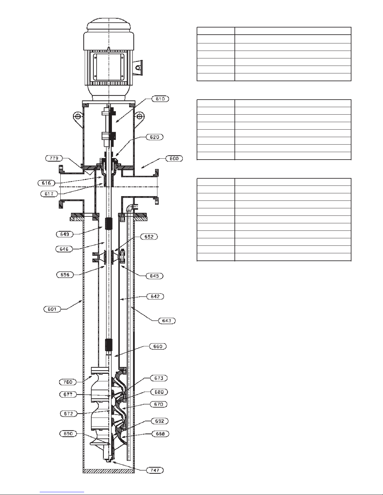
DISCHARGE HEAD ASSEMBLY
ITEM DESCRIPTION
600 DISCHARGE HEAD
610 COUPLING ASSEMBLY
617 SEAL HOUSING BEARING
616 SEAL HOUSING
779 SEAL HOUSING GASKET
620 MECHANICAL SEAL
COLUMN ASSEMBLY
642 COLUMN PIPE
645 COLUMN BOLTING
646 LINESHAFT
649 LINESHAFT COUPLING
652 BEARING RETAINER
656 LINESHAFT BEARING
643 CLEAN-OUT PIPE (OPTIONAL)
601 BARREL
BOWL ASSEMBLY
660 PUMP SHAFT
670 INTERMEDIATE BOWL
672 INTER. BOWL BEARING
673 IMPELLER
677 TAPERLOCK
680 WEAR RING (OPTIONAL)
760 HEX BOLT
692 SAND COLLAR
688 SUCTION BOWL/BELL
690 SUCTION BEARING
747 PLUG
Figure 1 VIC Pump with Solid Shaft Motor, Fabricated
T-Head, Mechanical Seal and Flanged Column
7
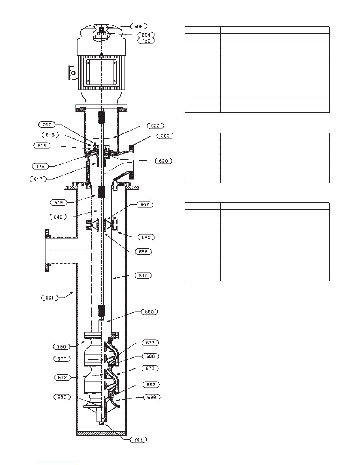
DISCHARGE HEAD ASSEMBLY
ITEM DESCRIPTION
600 DISCHARGE HEAD
604 ADJUSTING NUT
730 GIB KEY
608 HEAD SHAFT
616 STUFFING BOX
617 STUFFING BOX BEARING
618 SPLIT GLAND
620 PACKING
622 SLINGER
757 GLAND ADJUSTING SCREW
779 STUFFING BOX GASKET
COLUMN ASSEMBLY
642 COLUMN PIPE (FLG)
645 COLUMN BOLTING
646 LINESHAFT
652 BEARING RETAINER
656 LINESHAFT BEARING
649 LINESHAFT COUPLING
601 BARREL
BOWL ASSEMBLY
660 BOWL SHAFT
670 INTERMEDIATE BOWL
672 INTER. BOWL BEARING
673 IMPELLER
677 TAPERLOCK
680 WEAR RING (OPTIONAL)
760 HEX BOLT
692 SAND COLLAR
688 SUCTION BOWL/BELL
690 SUCTION BEARING
747 PLUG
8
Figure 2 VIC Pump with Cast L-Head, VHS Motor,
Packed stufng Box and anged
column
Installation – SECTION 3
When pumping unit is installed in a potentially
explosive environment, the instruction after
the symbol must be followed. Personal
injury and/or equipment damage may occur if these
instructions are not followed. If there is any question
regarding these requirements or equipment is to be
modified, please contact a Goulds Water Technology
representative before proceeding.
FOUNDATION AND PIPING
SUB BASE (SOLE PLATE) OR BARREL FLANGE
INSPECTION
Sub base and sole plate are terms in common use to
describe a general class of solid steel plates mounted
in grout (or bolted to steel structures) at the pumpfoundation interface.
1. Remove the sub base from the pump discharge head
or barrel flange, when shipped assembled.
2. Completely clean the underside of the sub base. It is
sometimes necessary to coat the underside of the sub
base with an epoxy primer. (This is available as an
option.)
3. Remove the rust preventative solution from the
machined topside with an appropriate solution.
SITE WITH CONCRETE FOUNDATION
1. A pump should have adequate space for operation,
maintenance, and inspection.
2. Sub base mounted pumps are normally grouted
on a concrete foundation, which has been poured
on a solid footing. The foundation must be able to
absorb any vibration and to form a permanent, rigid
support for the pumping unit.
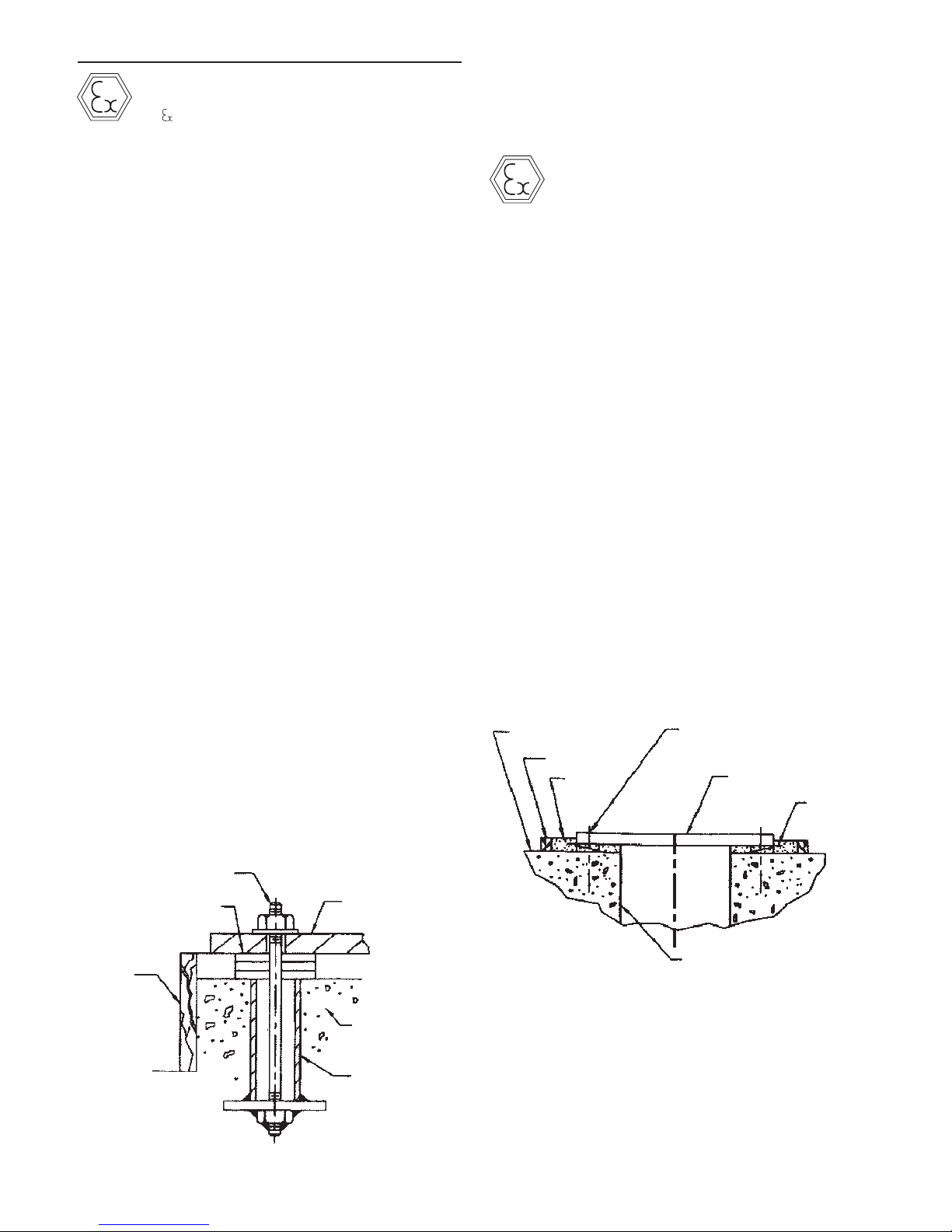
3. The foundation must be of adequate strength to
support the complete weight of the pump, plus the
weight of the liquid passing through it. A typical
installation will have bolts with a pipe sleeve 2 ½
times the bolt diameter embedded in the concrete.
Bolts should be sized and located in accordance
with the dimensions given on the Certified Pump
Outline Drawing, if provided. The pipe sleeve
allows movement for the final positioning of the
foundation bolts to conform to the holes in the sub
base flange. See Figure 3.
All equipment being installed must be properly
grounded to prevent unexpected static electrical
discharge. If not, a static electric discharge may
occur when the pump is drained and disassembled for
maintenance purpose.
4. Remove water and/or debris from anchor bolt holes/
sleeves prior to grouting. If the sleeve type bolts are
being used, fill the sleeves with packing or rags to
prevent grout from entering.
5. Carefully lower the sub base onto the foundation
bolts. Hand tighten the nuts.
6. Leveling the sub base may be done by several
methods. Two common methods are:
A. Using leveling wedges. This is shown in Figure 4.
B. Leveling nuts on the anchor bolts.
Regardless of the method, a machinist level must be
used for leveling.
NOTE: When using a machinist level, it is important
that the surface being leveled is free of all
contaminants, such as dust, to ensure an
accurate reading.
7. Level the sub base in two directions at 90º on the
machined surface. The levelness tolerance is 0.005
inches per foot for commercial, and 0.001 inches
per foot for API.
FOUNDATION
DAM
GROUT
CENTERLINE
ANCHOR BOLT
SUB BASE
LEVELING
WEDGES
BOLT
SHIMS
DAM
Figure 3
SUB BASE
FOUNDATION
SLEEVE
FLOOR SLEEVE
(OPTIONAL)
Figure 4
SUB BASE OR BARREL FLANGE GROUTING
1. Inspect foundation for dust, dirt, oil, chips, water,
etc. and remove any contaminants. Do not use oilbased cleaners as grout will not bond to it. Refer to
grout manufacturer’s instructions.
2. Build dam around foundation (See Figure 4).
Thoroughly wet foundation.
9

3. Pour grout between sub base or barrel flange and
WARNING
WARNING
CAUTION
concrete foundation, up to level of dam. Remove
air bubbles from grout as it is poured by puddling,
using a vibrator, or pumping the grout into place.
Non-shrink grout is recommended.
4. Allow grout to set at least 48 hours.
5. Tighten foundation bolts.
SITE WITH STRUCTURAL STEEL FOUNDATION
When the pump is mounted directly on a structural steel
frame, pumps shall be located directly over, or as near as
possible to, the main building members, beams or walls.
The barrel, discharge head mounting flange or sub base,
shall be bolted to the support to avoid distortion, prevent
vibration and retain proper alignment.
PUMP INSTALLATION
When pumping unit is installed in a potentially
explosive environment, the instruction after the
symbol must be followed. Personal injury and/
or equipment damage may occur if these instructions
are not followed. If there is any question regarding these
requirements or equipment is to be modified, please
contact a Goulds Water Technology representative before
proceeding.
Pumps of 20 feet (6 m) or less in length are usually
shipped assembled, with the exception of the driver,
mechanical seal with tubing and coupling assembly,
spacer or non spacer type. When provided, refer to the
Certified Pump Outline for the applicable base plate plan
for the location of anchor bolt holes.
INSTALLING A PARTIALLY ASSEMBLED PUMP
PIPING
Guidelines for piping are given in the “Hydraulic
Institute Standards”, available from: Hydraulic Institute,
9 Sylvan Way, Parsippany, NJ 07054-3802 and must be
reviewed prior to pump installation.
Never draw piping into place by forcing
the flange connections of the pump. Pipe
strain will adversely effect the operation of the pump
resulting in damage to the equipment and possible
physical injury.
1. All piping must be supported independently, and
line up naturally with the pump flange so that undue
pipe strain is not imposed on the pump.
2. DO NOT connect piping to pump until grout has
hardened and pump hold-down bolts have been
tightened.
3. It is suggested that expansion loops or joints, if used,
be properly installed in the discharge line. When
handling liquids at elevated temperatures expansion
joints are used, so linear expansion of piping will
not draw pumps out of alignment.
4. Carefully clean all pipe parts, valves and fittings, and
piping branches prior to assembly.
5. Isolation and check valves should be installed in
discharge line. Locate the check valve between
isolation valve and pump, this will permit inspection
of the check valve. The isolation valve is required
for regulation of flow, and for inspection and
maintenance of pump. The check valve prevents
pump or seal damage due to reverse flow through
the pump when the driver is turned off.
6. Increasers, if used, should be placed between pump
and check valves.
7. Cushioning devices should be used to protect the
pump from surges and water hammer if quickclosing valves are installed in the system.
1. If a base plate was supplied, install as described in
Foundation/Piping Section (page 9).
2. Clean the mounting surface of the plate and clean
bottom surface of discharge head mounting flange.
3. Check that all fasteners on the pump are tight, as it
is recognized that transportation and handling may
result in bolt relaxation.
4. Install the barrel (can) to discharge head O-ring
(743).
5. Sling through discharge head holes or thread two
eyebolts through bolt holes in mounting flange and
hoist unit into position over foundation.
NOTE: Eyebolts or sling should be rated to handle
in excess of the pump weight (see Outline
Drawing).
6. Lower the unit and carefully guide it so that unit
does not strike the side of the base plate. Continue
to lower unit until the discharge head flange engages
and rests firmly on the plate, then secure with
capscrews provided.
7. When a lineshaft is shipped separately check shaft
for straightness; average total run out should not
exceed 0.005” T.I.R. (0.127mm) for 10 feet (3 m).
Shaft must be within tolerance prior to installation.
8. Refer to remainder of this manual for complete
assembly, startup, maintenance, disassembly and
recommended lubricants for the pump.
INSTALLING THE BOWL ASSEMBLY
Do not work under a heavy suspended
object unless there is positive support and
safe guards, which will protect personnel, should a hoist
or sling fail.
Do not attempt to lift bowl assembly
by the pump shaft. This can result in
damaging the pump shaft.
10
 Loading...