

Page 1
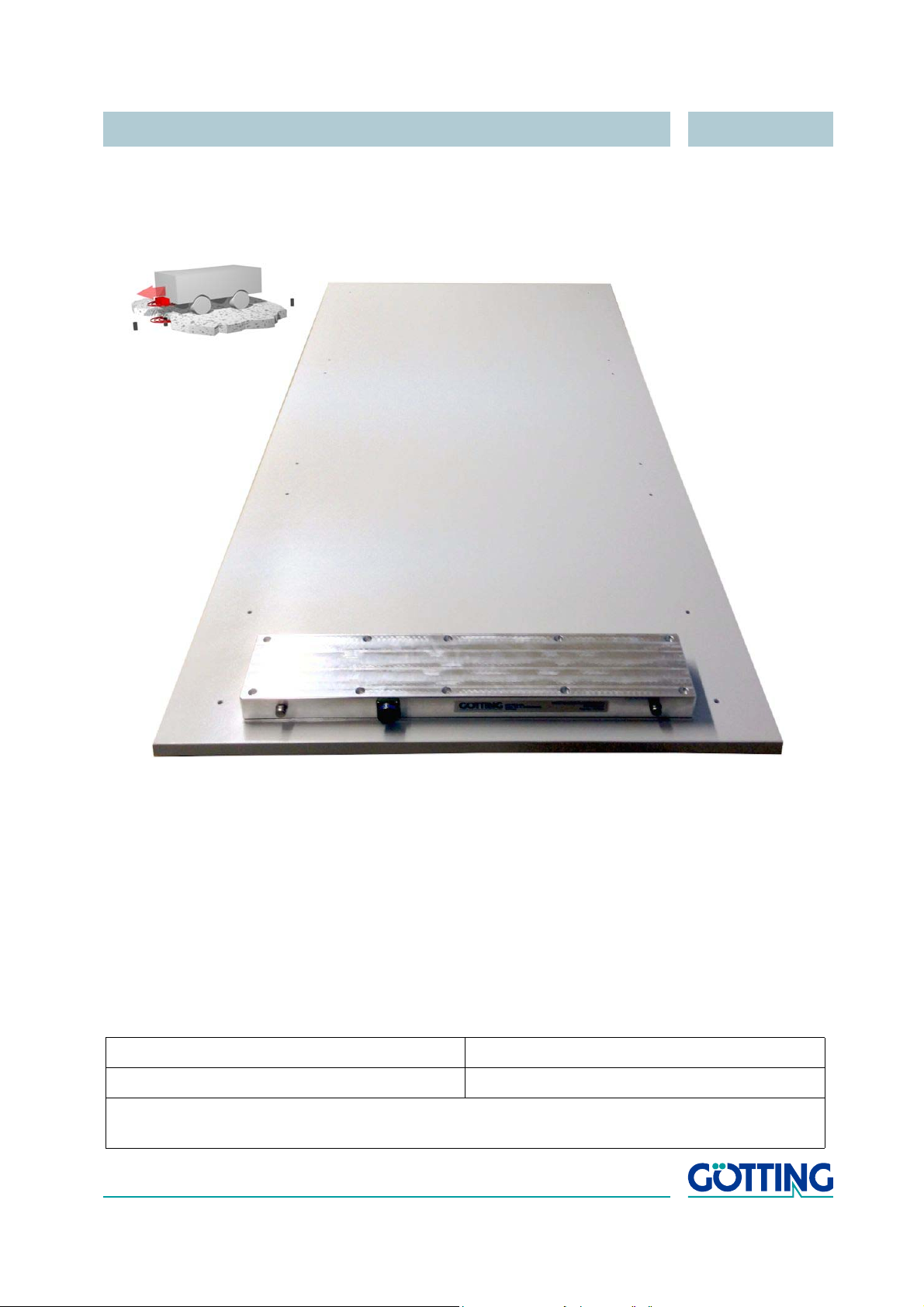
Technical Description HG 98860ZA
2-dim. Positioning and
Identification Antenna Outdoor
HG 98860ZA
English, Revision 04 Dev. by: WM / MH / DF
Date: 19.01.2015 Author(s): RAD / AF
Götting KG, Celler Str. 5, D-31275 Lehrte - Röddensen (Germany), Tel.: +49 (0) 51 36 / 80 96 -0,
Fax: +49 (0) 51 36 / 80 96 -80, eMail: [email protected], Internet: www.goetting.de
Page 2

Contents HG 98860ZA
Contents
1 Introduction.......................................................................5
1.1 System Components............................................................... 6
1.2 Function ................................................................................. 6
1.3 Application Example ............................................................... 7
1.4 Definitions .............................................................................. 7
2 Installation ........................................................................8
2.1 Transponder HG 70653ZA ...................................................... 8
2.2 Antenna HG 98860ZA ............................................................. 8
3 Installation / Commissioning ............................................10
4 Components and Operation .............................................15
4.1 Components in the Ground ................................................... 15
4.1.1 Transponders .............................................................................. 15
4.2 Transmitter-Receiver Antenna HG 98860ZA .......................... 15
4.2.1 Connection .................................................................................. 17
4.2.2 Turn-on characteristics ................................................................ 17
4.2.3 Interfaces .................................................................................... 18
4.2.3.1 Serial (RS 422) ....................................................................... 18
4.2.3.1.1 List of the system data which can be output.............. 18
4.2.3.1.2 List of commands ..................................................... 22
4.2.3.1.3 System Monitor ........................................................ 25
4.2.3.2 CAN Bus................................................................................. 25
4.2.3.2.1 Description of the CAN Protocol ............................... 25
4.2.3.2.2 CAN Bus Infrastructure............................................. 25
4.2.3.2.3 CAN Message Object 1 (Transmission Object).......... 25
4.2.3.2.4 CAN Message Object 2 (Transmission Object).......... 26
4.2.3.2.5 CAN Message Object 3 (Transmission Object).......... 26
4.2.3.2.6 CAN Message Object 4 (Reception Object)............... 27
4.2.3.3 Positioning Pulse .................................................................... 27
4.2.3.4 Analysis Interface ................................................................... 27
4.2.4 Software Download...................................................................... 28
4.2.5 Connection Cable HG 09240DB ................................................... 28
5 Software .........................................................................30
5.1 Terminal Program ................................................................. 30
5.2 Parameter Settings ............................................................... 30
5.3 System Monitor..................................................................... 31
5.3.1 How to start the monitor program ................................................. 31
5.3.2 How to work with the monitor program ......................................... 32
English, Revision 04, Date: 19.01.2015 2
Page 3

Contents HG 98860ZA
5.3.2.1 Main menu.............................................................................. 33
5.3.2.2 (S)erial Output ........................................................................ 35
5.3.2.3 (T)ime & Code ........................................................................ 37
5.3.2.4 (F)requency & Antenna Tuning................................................ 38
5.3.2.5 C(A)N-Parameters .................................................................. 39
5.3.2.6 Cs(v) ...................................................................................... 40
5.3.2.7 Display (X)Histogram / (-)........................................................ 41
5.3.2.8 Display (Y)Histogram / (+)....................................................... 42
5.3.2.9 (L)oad values to EEProm ........................................................ 43
5.3.2.10 (U)pdate Firmware .................................................................. 43
5.3.2.11 Import (1) / export (2) User Parameter..................................... 43
5.3.2.12 P(r)int Parameters .................................................................. 43
5.4 Software Update (Antenna Software) .................................... 44
5.4.1 Installation of the ST10-Flasher Program for Software Update ...... 44
5.4.2 Software Update.......................................................................... 44
6 Maintenance ...................................................................46
7 Trouble Shooting.............................................................47
8 Technical Data ................................................................48
8.1 Transmitter-Receiver Antenna............................................... 48
8.2 Connection Cable ................................................................. 49
9 Appendix.........................................................................50
A Procedure 3964R ............................................................................. 50
A.1 Data direction antenna -> SPS.................................................................50
A.2 Data direction SPS -> Antenna ................................................................51
B Procedure „transparent“ ................................................................... 51
B.1 Data direction antenna -> SPS.................................................................51
B.2 Data direction SPS -> antenna.................................................................51
C Influence of a metal plate on the antenna........................................ 52
D Influence of a metal frame on the antenna....................................... 52
E Influence of reinforcement steel mesh below the transponder......... 53
F Accuracy of the deviation calculation ............................................... 54
10 List of Figures .................................................................55
11 List of Tables .................................................................. 56
12 Index ..............................................................................57
13 Handbook Conventions....................................................58
14 Copyright and Terms of Liability ......................................59
14.1 Copyright.............................................................................. 59
14.2 Exclusion of Liability ............................................................. 59
English, Revision 04, Date: 19.01.2015 3
Page 4

Contents HG 98860ZA
14.3 Trade Marks and Company Names........................................ 59
English, Revision 04, Date: 19.01.2015 4
Page 5

Introduction HG 98860ZA
1 Introduction
The described antenna is designed to be used for positioning and/or trackguiding vehicles in rough outdoor environment, as all electronic components are fully sealed as
well as equipped with an extended temperature range. All important parameter set
tings, calibration and updates are carried out via an integrated serial interface.
Figure 1 Examples of automated vehicles using transponder systems
Antenna HG 98860ZA utilizes a completely new antenna concept, which has a large
reading area with a linear transponder positioning function. The antenna is so-called
2-dimensional, meaning that it outputs the Transponder code as well as the linear de
viation rectangular to the direction of travel, in direction of travel and in addition the
information “Crossing of the transponder“.
-
-
NOTE! The accuracy of the measured value for the position X (in direc-
tion of travel) only meets the specified accuracy (see Table 14 on
page 48) for travelling speeds of up to 1 m/s! For higher speeds
the positioning pulse has to be used as the reference which has
an accuracy within the millimeter range.
NOTE! The point at which the positioning pulse is generated is not
exactly the same point at which the position X is equal to zero (X
= 0) since these points are calculated using different procedures.
For the above described antenna, the use of Transponders of the type HG 70653ZA
(Read Write — RW) is mandatory.
The transponder antenna has an output format, which enables the user to configure
additional system information. This additional information, for example, may be used
by an external visualization system (e.g. vehicle control unit with display) and enables
statements regarding the condition and availability of antennas and transponders.
This system description refers to Transponder Positioning Antenna HG 98860ZA with
the firmware 98860MA1.0 or higher (also refer to
Figure 17 on page 33).
English, Revision 04, Date: 19.01.2015 5
Page 6
Introduction HG 98860ZA
HG 70653ZA
1.1 System Components
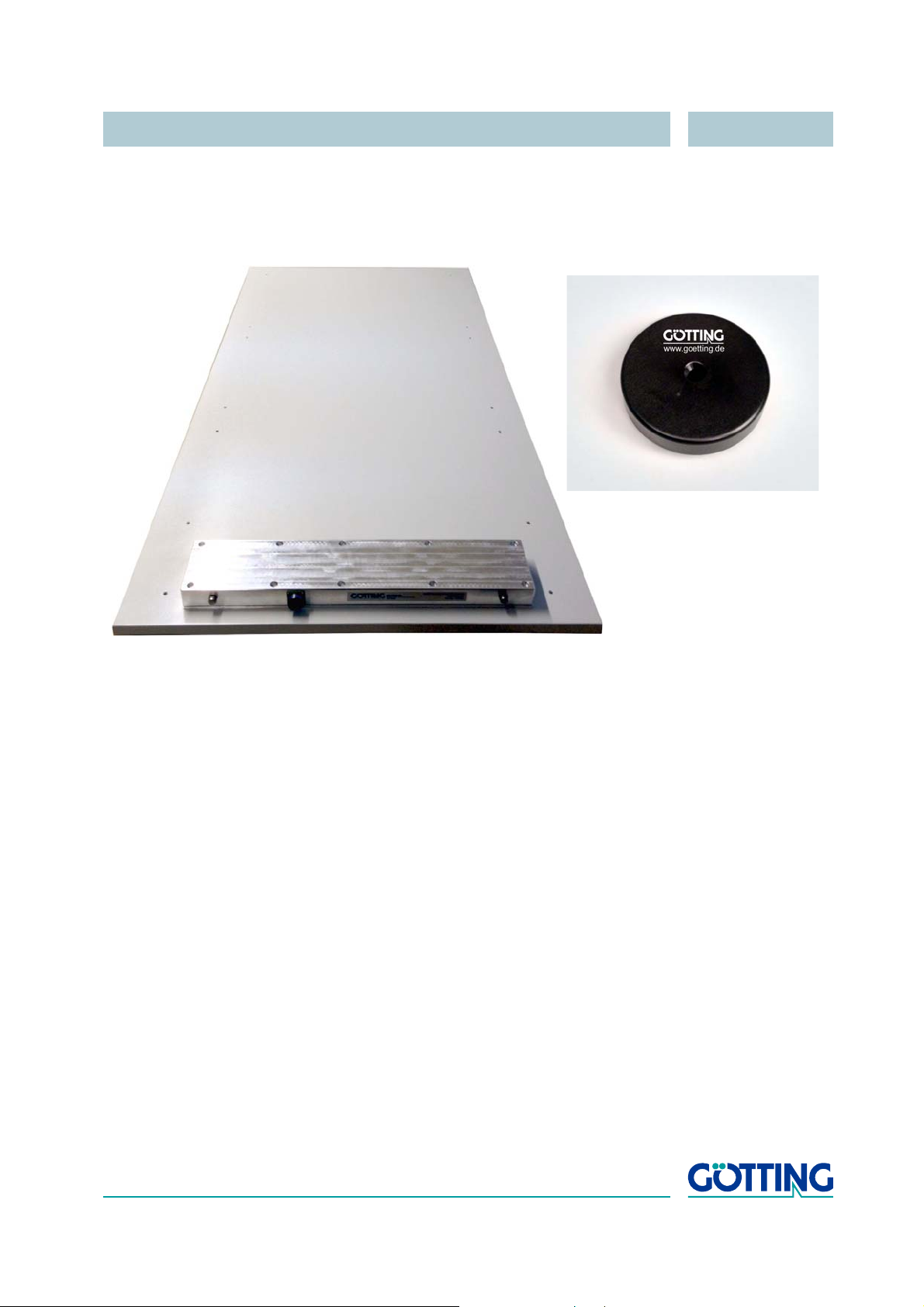
The 2-dimensional Positioning and Identification System using the antenna
HG 98860ZA consists of up to four different components:
Figure 2 System components (optional extras in brackets)
1. Transmitter-receiver antenna HG 98860ZA incl. interpreter
(refer to section 4.2 on page 15)
2. Transponder HG 70653ZA
(within the track; refer to section 4.1.1 on page 15)
3. Connection cable HG 09240DB
(not in this picture; refer to section 4.2.5 on page 28)
4. Washer set for mounting
(not in this picture, refer to section 2.2 on page 8)
5. Optional Read / Write Unit HG_81830YA
(not in this picture; refer to separate data sheet)
1.2 Function
As the antenna passes over the Transponder, it energizes the latter with an energy field
kHz. The transponder transmits its code back at half this frequency.
of 128
The relative Transponder position is measured. This relative position does not provide
the knowledge of the heading of the vehicle, as the field of the Transponder is rotationsymmetric to the longitudinal axis of the Transponder. Via a cable with the max. length
of 20 meters (RS
electronic.
422, CAN) Antenna HG 98860 is connected to the vehicle control
English, Revision 04, Date: 19.01.2015 6
Page 7
Introduction HG 98860ZA
-Y <— Deviation —> +Y
-X <— Direction of Travel —> +X
The internal interpreter unit decodes the Transponder code and interpolates the Transponder position rectangular to the direction of travel and in direction of travel from the
measured values.
Each coordinate axis crossing in direction of travel generates a positioning pulse of
adjustable duration.
In addition, various parameters of the antenna, such as current consumption and power supply voltage are measured and may be added to the serial output protocol.
1.3 Application Example
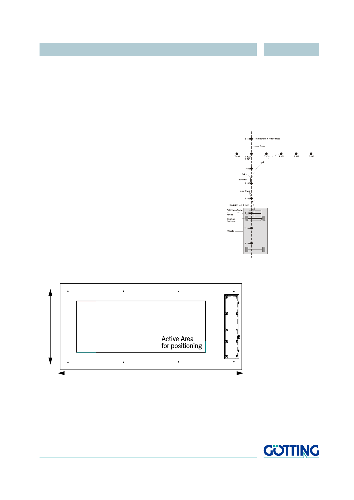
Figure 3 Track guiding a vehicle with one antenna
The figure shows a vehicle with an antenna frame for track guidance.
With the aid of the transponder (T 105) the deviation from the predeter
mined track is determined. With this information, an external computer is
able to determine the new direction required to return to the predeter
mined track as soon as possible (the external computer is not part of the
system). Rotary encoders enable changing the direction of travel when
ever necessary. Thus it is possible to switch tracks at predetermined
points. Again, the vehicle corrects its position independently upon
reaching the next transponder.
-
-
-
1.4 Definitions
The definitions and signatures used for this system and in this user´s
manual are defined according to the following drawing:
Figure 4 Polarity of the deviation
English, Revision 04, Date: 19.01.2015 7
Page 8
Installation HG 98860ZA
Antenna body
2 Installation
2.1 Transponder HG 70653ZA
Pay attention to the required minimum distances from metal, as the influence on positioning accuracy and range is dependent upon size and distance of metal parts. For
the same reason, the transponder should be mounted as vertically aligned as possi
ble. Please refer to the data sheet/mounting instructions for the transponder.
2.2 Antenna HG 98860ZA
-
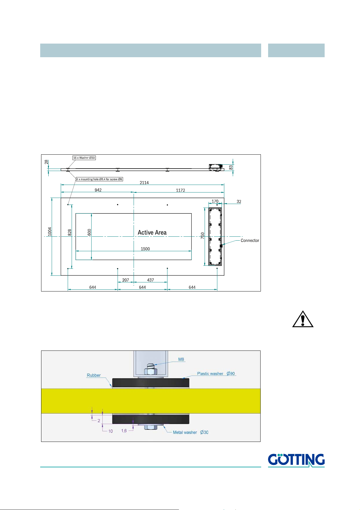
Figure 5 Antenna dimensions
ATT ENTION! When mounting the antenna, the washers that are part of the
scope of supply have to be used on both sides of each mounting
hole (see picture and text below)!
Figure 6 Application of the washers while mounting the antenna
English, Revision 04, Date: 19.01.2015 8
Page 9

Installation HG 98860ZA
To preserve the antenna body and especially avoid any dents or cracks in the area of
the mounting holes we would strongly recommend the following steps:
1. Apply the combined rubber / plastic washers with approx. 90 mm diameter to
secure a better distribution of the pressure. Place the rubber side on the
antenna to avoid surface damages.
2. Apply metal washers with approx. 30 - 40 mm diameter under head of screw/
nut.
3. Use self-locking nuts or screw locking varnish to fix screw fittings.
ATT ENTION! Do not exceed maximum torque of 10 NM.
To prevent any adverse effects on the system:
- The Antenna itself may not be mounted directly onto metal, on each side of the
Antenna, a minimum distance of 300
structures must be maintained (essential cabling and special mounting struts
excluded). The influence of metal behind the antenna is shown in the appendices,
see section
C on page 52.
mm to any larger electrically conductive
- For perfect operation of the transponder system, it is essential that there are no
interfering signals in the frequency range of 64 ±4
etc.)!
- Steel reinforcement structures located very close to the surface of the runway may
transform the Antenna energy in the ground to deviating locations in such a way
that the measured Transponder position is a faulty one, see section
kHz (e. g. chopped engines,
E on page 53.
English, Revision 04, Date: 19.01.2015 9
Page 10

Installation / Commissioning HG 98860ZA
3 Installation / Commissioning
NOTE! Check the operating voltage before connecting! Although the
RS
422 / CAN interface is largely insensitive to interferences, the
cable should not lie directly next to power supply cables.
Connect the antenna with the vehicle control unit using the delivered cable.
Connect a laptop to the antenna using the serial interfaces of both devices. The aid of
a suitable RS 422 to RS 232 converter may be necessary for this step (the interface
converter is not part of the scope of supply). Then start the monitor program as de
scribed in section 5.3 on page 31.
Default Values The standard setting of the system is „Monitor only“ as listed in
section
need for the user to download a command file. However, please
pay attention to the fact that these may have been altered by a
different user!
1. If the antenna is mounted next to metal, it must be re-calibrated (also refer to
section
5.3.2.3 on page 37), it is useful to record a complete test run over the set track.
The serial interface of antenna HG 98860ZA may be used accordingly (refer to
section
interface (section 4.2.3.4 on page 27).
2.2 on page 8). In order to set the positioning threshold (refer to section
5.3.2.6 on page 40). In addition to this you can use the TxD 232 debug
5.3.1 on page 31 at 38400 bd. Thus it will start without the
-
2. Move a transponder into reception range.
The voltage S should increase considerably. The code must be detected immediately and the number of readings must be continuously counted up to 255.
3. Remove the transponder again from the reception range.
While no transponder is located within the antenna field, the voltage S must
decrease to a very small value. The display of the code and the number of read
ings, if applicable, remains identical. If this is not the case, interferences in the
frequency range of 64
As long as no errors have occurred, save any altered parameters and exit the monitor
program. If certain parameters are altered, a system reset is necessary (turn off and
reactivate the antenna) as described in the corresponding section of the monitor pro
gram (section 5.3). Now the system has been correctly put into operation.
kHz are being induced.
-
-
English, Revision 04, Date: 19.01.2015 10
Page 11
Installation / Commissioning HG 98860ZA
Low Interference Level
Undisturbed Transponder Decoding
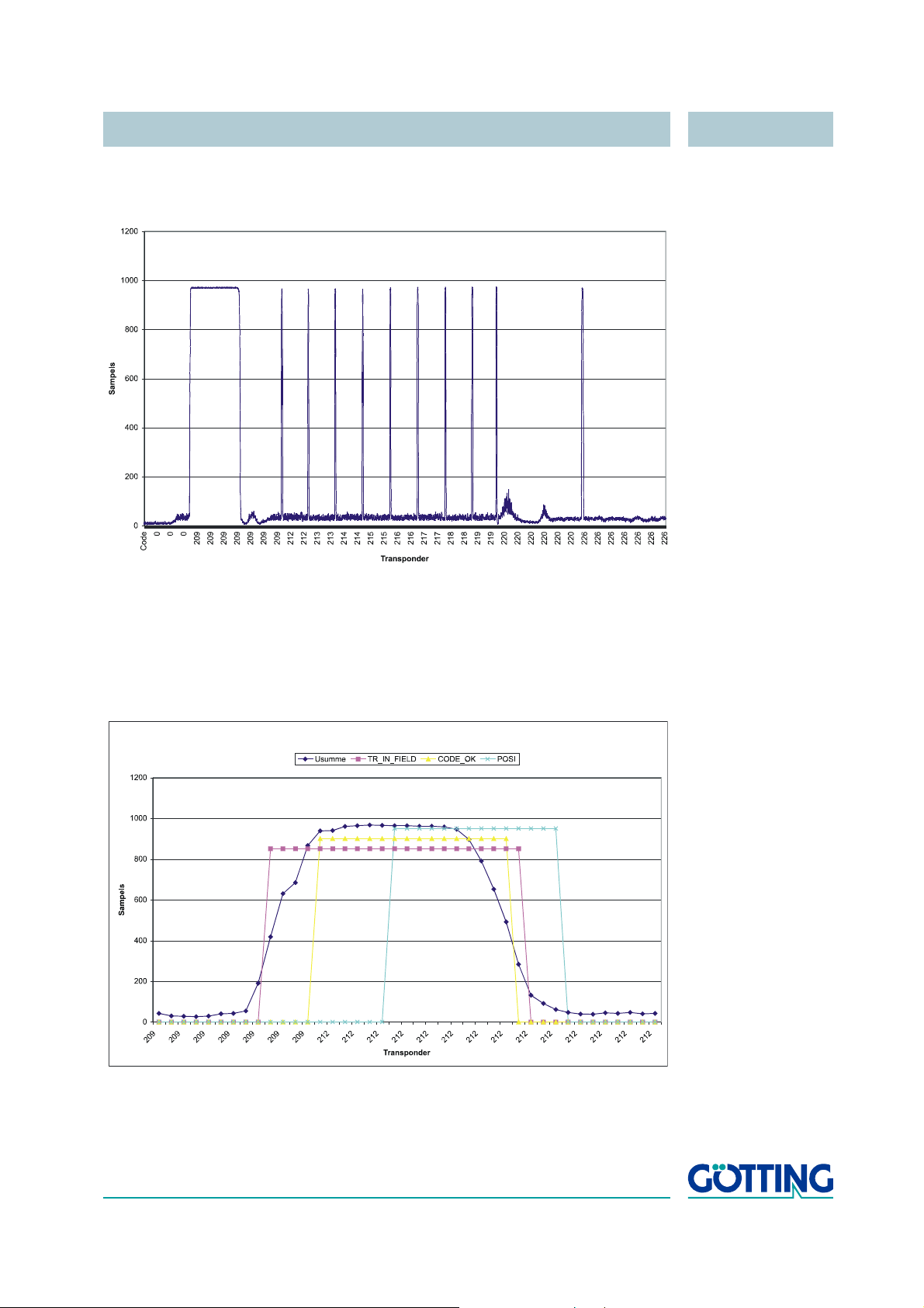
The following diagrams show examples of logged system data:
Figure 7 Diagram: Commissioning Protocol / insignificant interference level; shown is
the sum voltage over the travelled distance
The above diagram shows the sum voltage (in units) over the travelled distance. The
noise is in this case approx. 50 units, the transponder signal approx. 950 units. The
Transponder decoding is perfect, as also shown in the following diagram:
Figure 8 Diagram: Commissioning Protocol / undisturbed Transponder decoding
English, Revision 04, Date: 19.01.2015 11
Page 12
Installation / Commissioning HG 98860ZA
High Interference Level
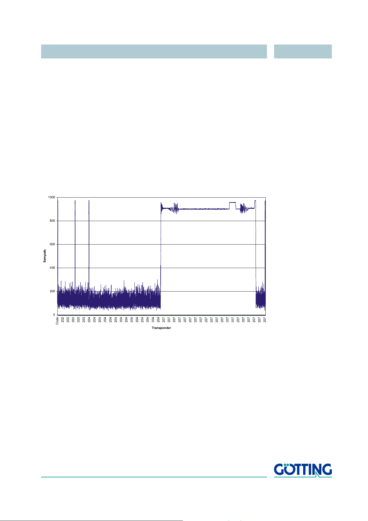
During each Transponder crossing, the sum voltage increases initially. Once the
threshold Threshold for Decoding has been exceeded, the bit
TRANS_IN_FIELD is set. Following 4 x 8
is decoded. The duration depends on the setting for Number of Equal Codes within
the menu Time & Code. In this example, this parameter is = 2, i.
ceived code is compared to 2 already received codes.
Once the center of the Antenna has been crossed, the POSI-Puls is generated. Its
duration is adjustable. The bits TRANS_IN_FIELD and CODE_OK are deleted, when
ever the sum voltage decreases under the value for Threshold for Decoding. In
the shown example there is spare time of 6 x 8
Puls.
The following protocols show the influences of high interference levels on the Antenna
performance.
ms (= 4 data points) the Transponder code
e., the newly re-
-
ms for the generation of the POSI-
Figure 9 Diagram: Commissioning Protocol / high interference level; shown is the
sum voltage over the traveled distance
The interference level reaches up to 300 units. At Transponder 207 the noise is at such
a level that it even influences the Transponder signal. As a result it takes 9 x 8 ms until
the Transponder 207 has been decoded (refer to
crossing speed 9 x 8 ms is still sufficient for generating a POSI-Puls, but at high
speed it would no longer be possible to decode this Transponder.
Figure 10 on page 13). For the slow
English, Revision 04, Date: 19.01.2015 12
Page 13
Installation / Commissioning HG 98860ZA
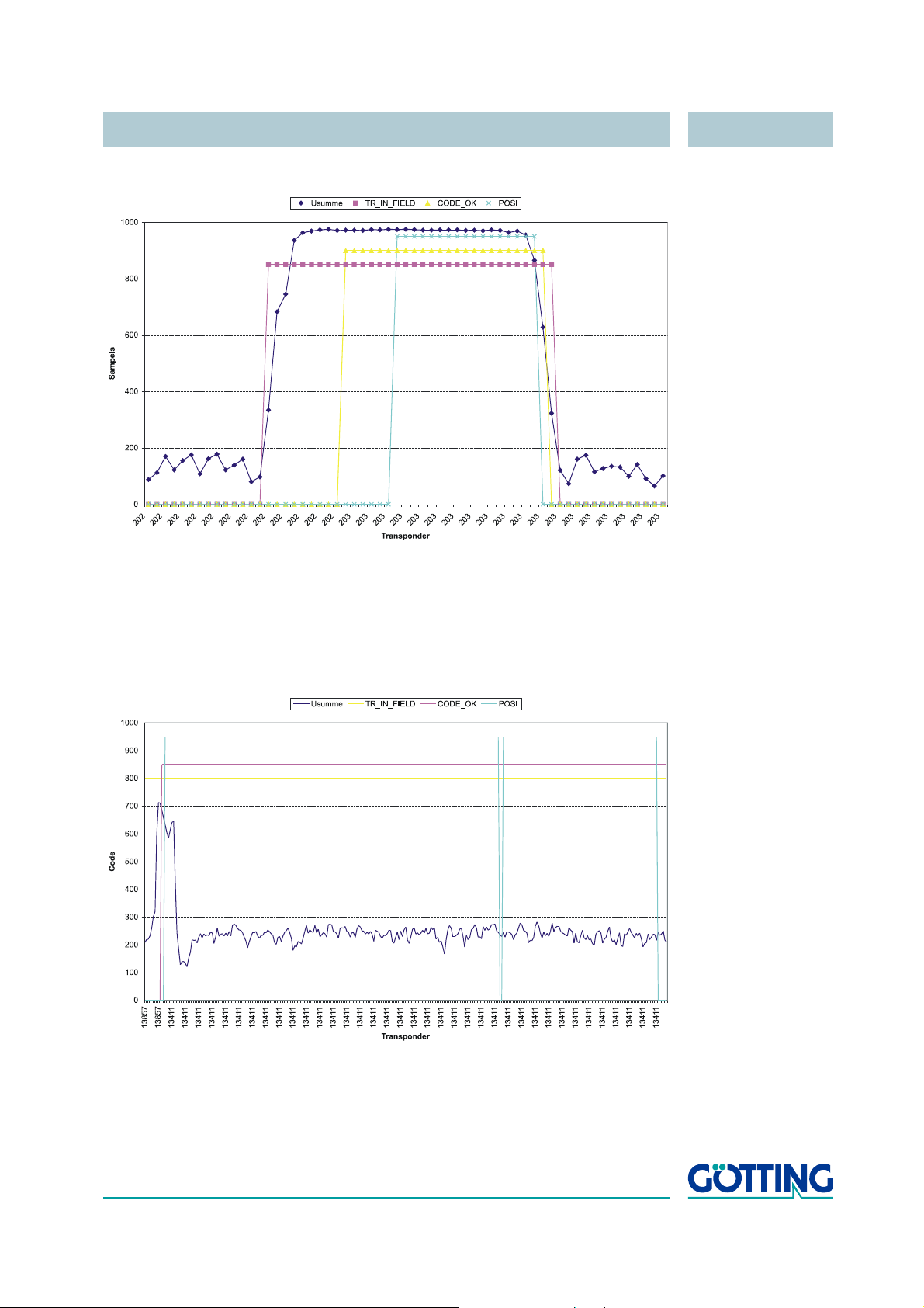
Jammed Decoding (function still ensured)
False POSI Pulse generated by noise and threshol d se t too low
Figure 10 Diagram: Commissioning Protocol / jammed decoding (function still en-
sured)
The following diagram shows a case in which false POSI-Pulses are generated
through wrongly set parameters for Threshold for Decoding and/or
Threshold for Positioning.
Figure 11 Diagram: Commissioning Protocol / false POSI Pulse generated through
noise and threshold set too low
English, Revision 04, Date: 19.01.2015 13
Page 14

Installation / Commissioning HG 98860ZA
For this example, the thresholds are set to 100 units. The bit TRANS_IN_FIELD is permanently set. Following a successful Transponder decoding, initially a correct POSI-
Puls is generated. However, as the software does not realize that the Transponder
leaves the Antenna field (the noise is stronger than the set 100 units for the threshold),
each zero crossing of the difference voltage (not shown in the diagram) will generate
another POSI-Puls.
English, Revision 04, Date: 19.01.2015 14
Page 15
Components and Operation HG 98860ZA
4 Components and Operation
4.1 Components in the Ground
4.1.1 Transponders
As reference markers only transponders of the type HG 70653ZA can be used. These
are special high signal types due to the large reading distance possible with this an
tenne. Please refer to the separately available data sheet for HG 70653ZA for further
information about the transponder.
Range and accuracy of positioning are influenced by:
- any large metal pieces (sheets) on the ground.
- proximity of any floor reinforcement
- inductive loops, as they are created e. g. by steel building mats, have a greater
influence. Individual metal poles have little effect. Those may partially be within
the metal-free area.
The following environmental conditions have no effect on the system:
- snow, ice, water.
-
- oil, tar, earth, dirt, etc.
4.2 Transmitter-Receiver Antenna HG 98860ZA
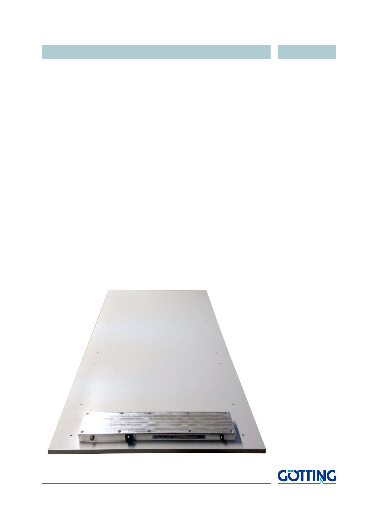
This antenna has RS 422 and CAN interfaces.
Figure 12 Photo Transmitter-Receiver Antenna HG 98860ZA
English, Revision 04, Date: 19.01.2015 15
Page 16
Components and Operation HG 98860ZA
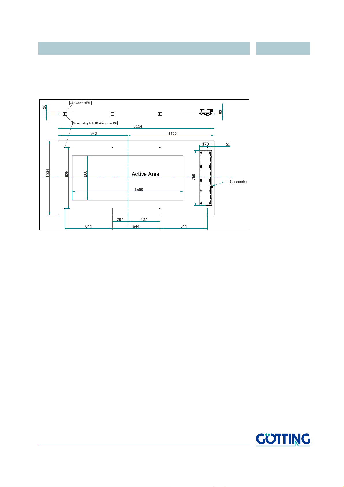
The antenna systems and the pre-amplifiers are housed in a casing with the below given dimensions. In order to limit the weight, the casing has been filled with construction
foam, which serves as sealing compound as well as the stabilizing elements. The ca
ble (the connecter) exits at one side of the antenna.
-
Figure 13 Drawing Antenna HG 98860ZA (with casing dimensions)
The interpreter is integrated in the antenna casing. The electronics are varnished. A
thermostat controlled heater is included.
English, Revision 04, Date: 19.01.2015 16
Page 17
Components and Operation HG 98860ZA
Socket (pin)
front view
4.2.1 Connection
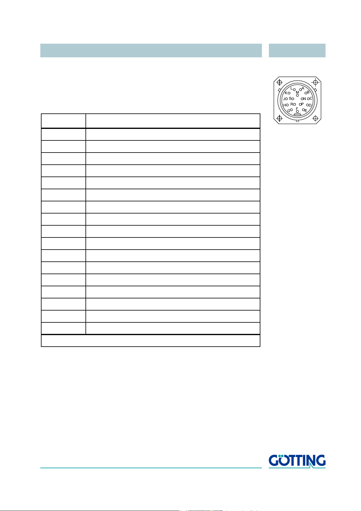
Figure 14 16-pin Antenna connection socket
The antenna is equipped with a 16 pin connection socket. The pin allocation is as follows:
Contact HG 98860ZA (RS 422)
A +24 V (antenna)
B GND (antenna)
C n.c.
D SL Rx
E Rx 422+ *)
F Rx 422- *)
G Tx 422+ *)
H Tx 422- *)
J +20 mA Positioning Pulse
K -20 mA Positioning Pulse
L CAN_H
M CAN_L
N Signal Ground
P SL TX
R Tx RS 232 output for data logging
S Casing
Casing shield
*) = Rx and Tx are related to the antenna.
Tab le 1 Allocation of the 16 pin Antenna Connection Socket
The two positioning pins are lead through separately and internally neither connected
to +24
V nor to GND, as in some applications it is essential that strict potential separation is maintained. For security reasons, a 20 mA current limitation for these outputs
is implemented within the Antenna. Thus if, e.
possible to connect pin 9 with +24
V and pin 10 via a 1 KOhm resistance with GND.
g., a 24 V voltage output is required it is
4.2.2 Turn-on characteristics
Upon applying the operating voltage, the antenna requires 10 seconds startup time.
During this period, it is possible to start a firmware update (also refer to section
page 44).
English, Revision 04, Date: 19.01.2015 17
5.4 on
Page 18

Components and Operation HG 98860ZA
21
Byte
Telegram
------------------------- 11
Bit
Byte
----------- - 38400
Bit
s
------ - 6
ms
Telegram
-------------------------=
Following this period of time, the actual program starts. If configured accordingly (also
refer to
procedure takes another 16 seconds.
4.2.3 Interfaces
4.2.3.1 Serial (RS 422)
The serial output may be configured in various ways. The transmission rate is adjustable at 19200 or 38400 Bd, the output protocol may be chosen as either „transparent“
or „3964R“. Apart from that, the content of the output telegrams is configurable. From
a parameter list the required parameters may be selected.
4.2.3.1.1 List of the system data which can be output
One Telegram consists of max. 21 user bytes. The minimum update rate at 38400 Bd
is then calculated as follows:
Figure 15 Formula: Minimum update rate
As the transmission is binary, it is possible to add further (DLE) characters to the procedure when using the 3964R-procedure.
Figure 21 on page 38), the transmission coils will be automatically tuned. This
All multiple-byte variables are output either with the highest byte or the lowest byte first
(adjustable)!
The 8 bit check sum is only output when using the transparent protocol and includes
the start pulse. The start pulse, as well as the check sum (protocol transparent), can
not be removed from the data block.
-
English, Revision 04, Date: 19.01.2015 18
Page 19

Components and Operation HG 98860ZA
Table of the data words of a telegram with 21 byte length.
Byte # Length Value Type Description
1 1 Byte 0x0000.0001 ASCII-061 : „=“ Start pulse (Default: „=“)
2,3 2 Byte 0x0000.0002 signed short Y-Position: Y [mm] (lateral deviation)
within the range of -750 .. 0 .. +750
In case of an invalid value (no Transponder
detected) = 32767 *)
4,5 2 Byte 0x0000.0004 signed short X-Position: X [mm] (longitudinal deviation)
within the range of -300 .. 0 .. +300
In case of an invalid value (no Transponder
detected) = 32767 *)
6,7 2 Byte 0x0000.0008 unsigned short 16 bit Transponder code
8,9 2 Byte 0x0000.0010 signed short Voltage generated by the transponder in the
reference coils in [units]
10,11 2 Byte 0x0000.0020 unsigned short voltage generated by the Transponder in the
positioning coils in [units]
12 1 Byte 0x0000.0040 unsigned char operational voltage for the Antenna [100 mV]
13 1 Byte 0x0000.0080 unsigned char power consumption [10 mA]
14 1 Byte 0x0000.0100 signed char temperature within the antenna [oC]
15 1 Byte 0x0000.0200 unsigned char number of readings during the latest Transpon-
der crossing
16,17 2 Byte 0x0000.0400 unsigned short receiver frequency [10 Hz]
18,19 2 Byte 0x0000.0800 unsigned short transmitter frequency [10 Hz]
20, 21 2 Byte 0x0000.1000 unsigned short system status in binary encoding
(22) 1 Byte unsigned char check sum, only in transparent protocol!
XOR operation of all bytes including the start
character.
*) = In case that either the position for x or y exceeds its valid range, both values are set to 32767.
Tab le 2 Data words in a telegram with 21 byte length
English, Revision 04, Date: 19.01.2015 19
Page 20
Components and Operation HG 98860ZA
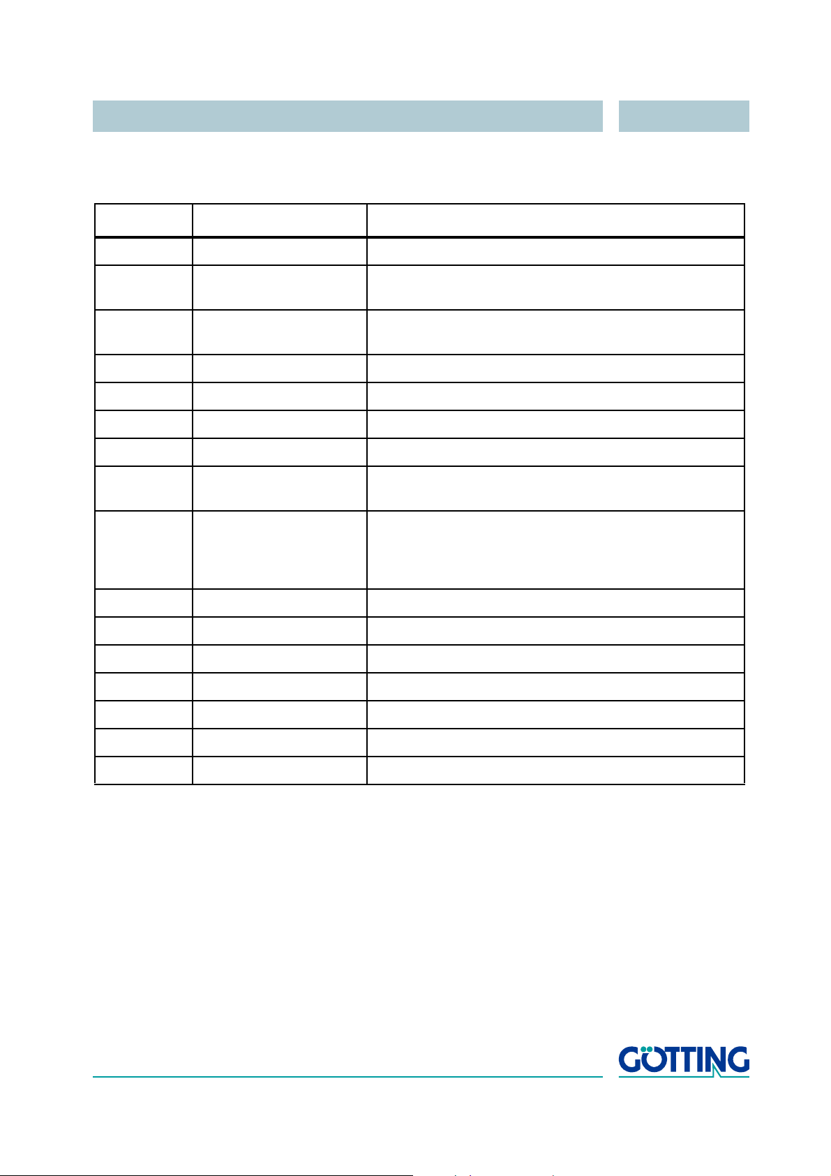
In the following table you will find a list of the binary codes used to describe the system
status (for byte # 20 and 21 in
Value Name Description
0x0001 DEC_HW_ERROR code decoder hardware error
0x0002 CODE_PAR_ERR reception of transponder code with parity error or Hi-Nibble
0x0004 RX_NOISE Set whenever TRANS_IN_FIELD was set but no codes
0x0008 NO_SLAVE_COM No communication with slave processor
0x0010 EEPROM_ERROR parameter E²Prom not addressable
0x0020 PARAM_CRC_ER parameter block not safe
0x0040 POT_ERROR IIC-Bus Potis not addressable
0x0080 F_ERROR Transmitting or receiving oscillator not tuned to the set fre-
Table 2 ):
received
were received
quency
0x0100 ESTIMATE If the exact Transponder Position cannot be determined
due to wrong reading distances or e.
g. steel reinforcements in the ground, an estimated value with the accuracy
of ±46
mm is determined and this bit is set
0x0200 TRANS_IN_FIELD transponder is being detected *)
0x0400 CODE_OK Code decoded without errors *)
0x0800
0x1000 POSIPULS Transponder has crossed the Antenna center
0x2000
0x4000
0x8000 HEATER_ON Internal heating active
Tab le 3 Possible system status messages
*) These bits are deleted as soon as the Transponder leaves the
Antenna reception range.
Example:
System status 0x0018
Description NO_SLAVE_COM and EEPROM_ERROR.
This status message 0x0002 may also occur during an ordinary transponder crossing, if the code transmission is aborted due to decreasing output level.
The connection between „number of readings“ and „system status“ is as follows:
English, Revision 04, Date: 19.01.2015 20
Page 21

Components and Operation HG 98860ZA
The antenna approaches a transponder:
- voltages S and D increase
- once the voltages S or D exceed the set „Threshold Decoding/Calculation“
1. the counter „number of readings“ is reset to 0
2. the status bit „TRANS_IN_FIELD“ (0x200) is set
- codes are decoded and the counter „number of readings“ is incremented
1. if the value is larger than „number of equal codes“, the status bit
„CODE_OK“ (0x400) is set and the code output.
2. each decoded code now increases the counter „number of readings“
3. if the value of „number of equal codes“ is = 0, each received code is output
4. if the value of „number of equal codes“ is not = 0, the detected code is not
renewed
The antenna departs from a transponder:
- voltages S and D decrease
- once the voltages S or D fall below the set „Threshold Decoding/Calculation“, the
status bits „CODE_OK“ (0x400) and „TRANS_IN_FIELD“ (0x200) are reset
The counter „code readings“ stops, either whenever the line or column parities of the
code are wrong or no startsyncs were received. However, the bit „CODE_OK“ is
cleared only when the voltages U
Normally, the value for „number of equal codes“ is set to a value > 0. In this case, the
code is only updated once, when the required number of equal codes was success
fully decoded and then output without amendments until a new code is decoded at the
next transponder.
and Ud fall below the defined thresholds.
s
-
English, Revision 04, Date: 19.01.2015 21
Page 22
Components and Operation HG 98860ZA
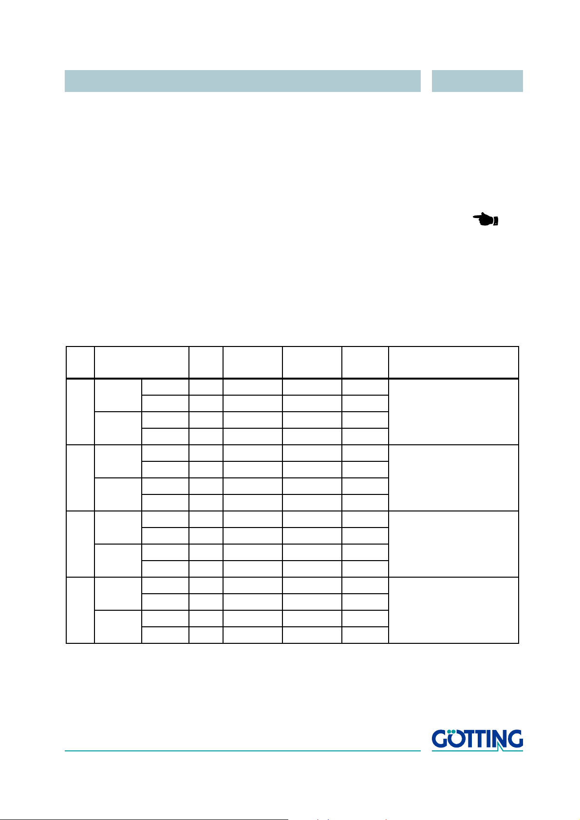
4.2.3.1.2 List of commands
A command telegram always consists of four bytes, including the actual command
and the parameters. When using the procedure „transparent“ it is, in addition, necs
sary to transfer one start character and a check sum (XOR operation of all bytes including the start character).
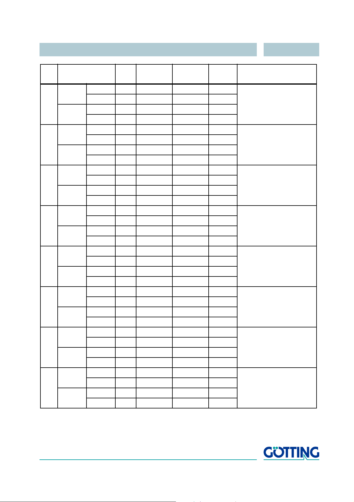
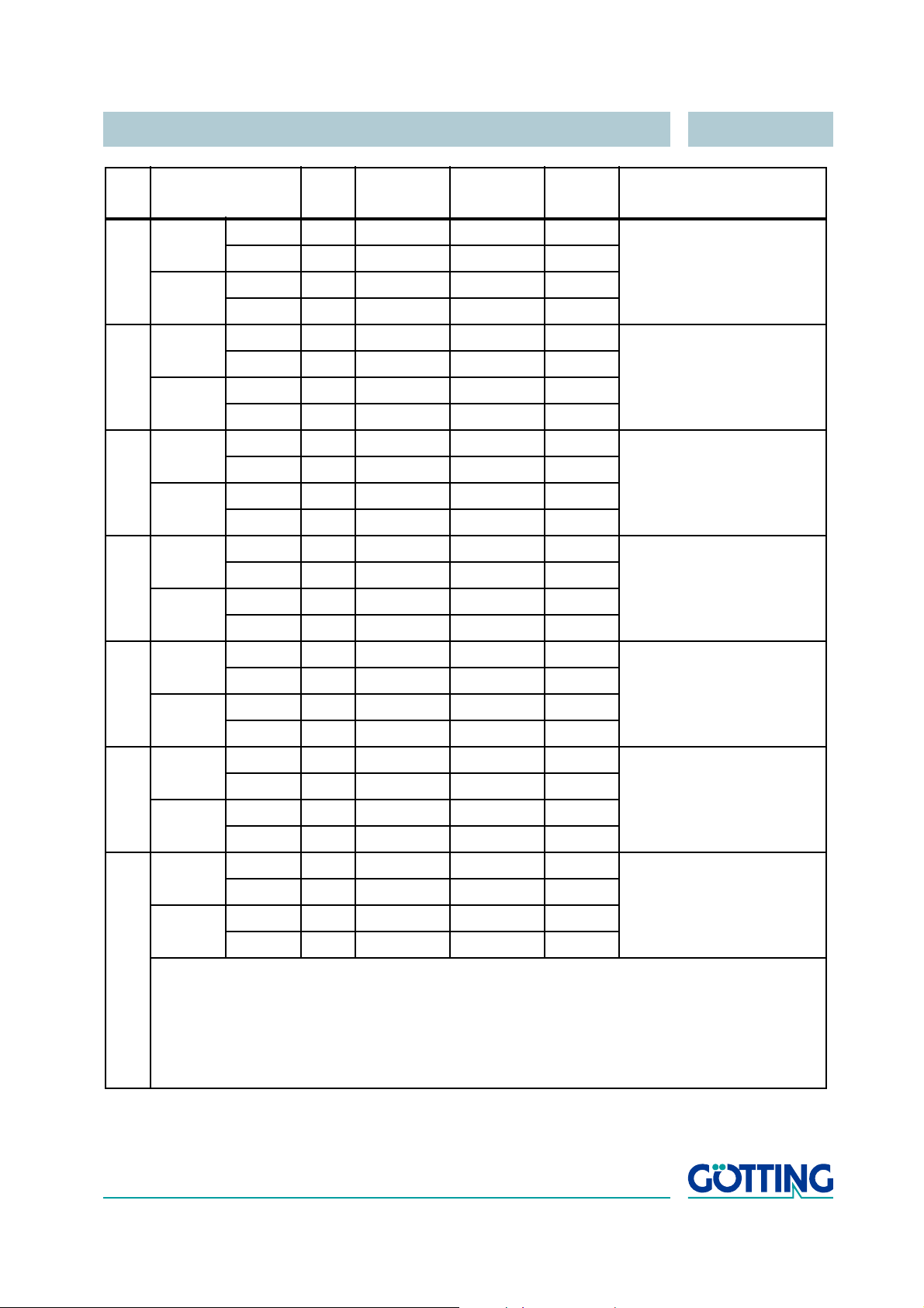
There are 19 predefined commands:
NOTE! The table below is valid for 'High Byte First'-transmission. For
'Low Byte First'-transmission the order of command and parame
ter bytes has to be changed.
The duration of 'Tune Antenna Once'-command is maximal 10
seconds for 16 tuning steps.
The monitor mode should not be used during normal operation
(e. g. from a PLC), as the following signal output is not according
to a ’transparent’ or ’3964R’ protocol but only suitable for output
on a VT52-terminal and used for the alteration of parameters.
-
-
No. Procedure Start
1
HEX 4D164F
3964R
ASCII MO NI
transparent
2
HEX 3D
16
ASCII = MO NI 8
HEX 541655
3964R
ASCII TU NE
transparent
3
HEX 3D
16
ASCII = TU NE 7
HEX 531654
3964R
ASCII ST 01
transparent
4
HEX 3D
16
ASCII = ST 01 8
HEX 531654
3964R
ASCII ST 02
transparent
HEX 3D
16
ASCII = ST 02 ;
Command
Bytes
16
4D164F
541655
531654
531654
16
16
16
16
16
16
16
Parameter
Bytes
4E1649
4E1649
4E1645
4E1645
301631
301631
301632
301632
16
16
16
16
16
16
16
16
Check Sum
38
16
37
16
38
16
3B
16
Description
Switch to monitor mode
Tune antenna once
Set tuning value to 1
Set tuning value to 2
Tab le 4 List of the system commands (part 1 of 3)
English, Revision 04, Date: 19.01.2015 22
Page 23
Components and Operation HG 98860ZA
No. Procedure Start
5
HEX 531654
3964R
ASCII ST 03
transparent
6
HEX 3D
16
ASCII = ST 03 9
HEX 531654
3964R
ASCII ST 04
transparent
7
HEX 3D
16
ASCII = ST 04 >
HEX 531654
3964R
ASCII ST 05
transparent
8
HEX 3D
16
ASCII = ST 05 ?
HEX 531654
3964R
ASCII ST 06
transparent
9
HEX 3D
16
ASCII = ST 06 <
HEX 531654
3964R
ASCII ST 07
Command
Bytes
16
531654
531654
531654
531654
16
16
16
16
16
16
16
16
Parameter
Bytes
301633
301633
301634
301634
301635
301635
301636
301636
301637
16
16
16
16
16
16
16
16
16
Check
Sum
39
16
3E
16
3F
16
3C
16
Description
Set tuning value to 3
Set tuning value to 4
Set tuning value to 5
Set tuning value to 6
Set tuning value to 7
10
transparent
3964R
HEX 3D
ASCII = ST 07 =
HEX 531654
16
531654
16
16
ASCII ST 08
11
transparent
3964R
HEX 3D
ASCII = ST 08 2
HEX 531654
16
531654
16
16
ASCII ST 09
12
transparent
3964R
HEX 3D
ASCII = ST 09 3
HEX 531654
16
531654
16
16
ASCII ST 10
transparent
Tab le 4 List of the system commands (part 2 of 3)
HEX 3D
ASCII = ST 10 ;
16
531654
16
301637
301638
301638
301639
301639
311630
311630
16
16
16
16
16
16
16
3D
32
33
3B
16
Set tuning value to 8
16
Set tuning value to 9
16
Set tuning value to 10
16
English, Revision 04, Date: 19.01.2015 23
Page 24
Components and Operation HG 98860ZA
No. Procedure Start
13
HEX 531654
3964R
ASCII ST 11
transparent
14
HEX 3D
16
ASCII = ST 11 :
HEX 531654
3964R
ASCII ST 12
transparent
15
HEX 3D
16
ASCII = ST 12 9
HEX 531654
3964R
ASCII ST 13
transparent
16
HEX 3D
16
ASCII = ST 13 8
HEX 531654
3964R
ASCII ST 14
transparent
17
HEX 3D
16
ASCII = ST 14 ?
HEX 531654
3964R
ASCII ST 15
Command
Bytes
16
531654
531654
531654
531654
16
16
16
16
16
16
16
16
Parameter
Bytes
311631
311631
311632
311632
311633
311633
311634
311634
311635
16
16
16
16
16
16
16
16
16
Check
Sum
3A
16
39
16
38
16
3F
16
Description
Set tuning value to 11
Set tuning value to 12
Set tuning value to 13
Set tuning value to 14
Set tuning value to 15
18
transparent
3964R
HEX 3D
ASCII = ST 15 >
HEX 531654
16
531654
16
16
ASCII ST 16
19
transparent
3964R
HEX 3D
ASCII = ST 16 =
HEX 531650
16
531654
16
16
ASCII SP *)
transparent
HEX 3D
ASCII = SP *) *)
16
531650
16
*) No ASCII-coded values
**) Depending on the parameters used. Examples:
- Level should be set to 1000 (3E816)
The transparent telegram is: 3D16531650160316E816D5
- Level should be set to 300 (12C16)
The transparent telegram is: 3D165316501601162C1613
Tab le 4 List of the system commands (part 3 of 3)
311635
311636
311636
0 ... 3E8
0 ... 3E8
16
16
16
16
16
3E
3D
**)
16
16
16
Set tuning value to 16
16
Set postioning level
(0 <= level < 1024)
English, Revision 04, Date: 19.01.2015 24
Page 25
Components and Operation HG 98860ZA
4.2.3.1.3 System Monitor
The system may be configured via menus in monitor mode. Refer to section 5.3 „System Monitor“ on page 31.
4.2.3.2 CAN Bus
4.2.3.2.1 Description of the CAN Protocol
It possible to configure the Basic or the Full-CAN-Mode. The CAN parameters are set
via the system monitor. The internal CAN module is based on the CAN specifications
V2.0 part B. Standard or Extended frames are transmitted (to be configured). It is also
possible to configure the bit timing as well as the identifier within the system monitor.
Different CAN message objects can be output. In addition it is to be set whether telegrams are to be output permanently at the set update rate or only as long as a Transponder is within range. Remote operation is also possible. Objects are activated
within the CAN menu, through the input of an address unequal 0. Message Object 3
is used for the analysis of the system behavior.
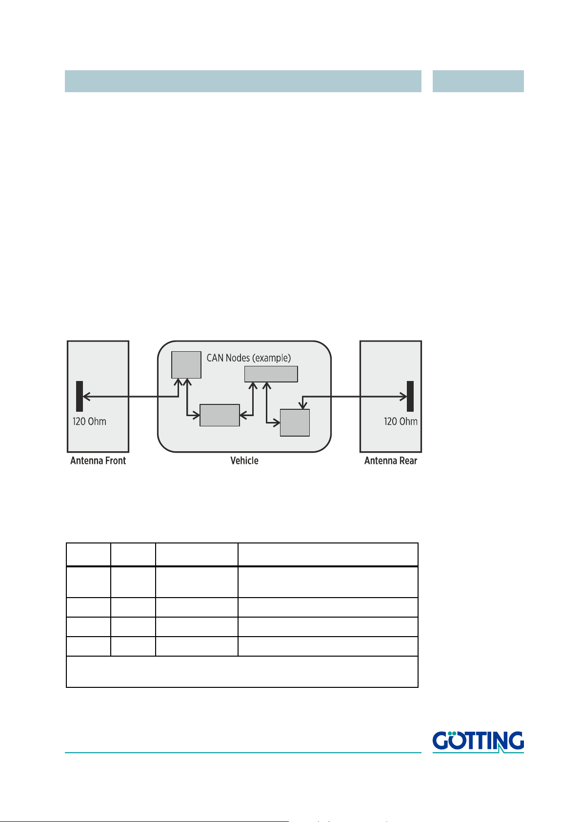
4.2.3.2.2 CAN Bus Infrastructure
Figure 16 CAN Bus Infrastructure (Example)
The terminating resistors (120 Ohm) are integrated within the antennas. The antennas
thus have to be at both ends of the CAN network.
4.2.3.2.3 CAN Message Object 1 (Transmission Object)
Byte # Length Type Description
1,2 2 Byte unsigned short System status information according to
Table 3 on page 20
3,4 2 Byte unsigned short 16 Bit Transponder code
5,6 2 Byte signed short Deviation X [mm] *
7,8 2 Byte signed short Deviation Y [mm] **
* X = Direction of travel
** Y = Lateral deviation
Tab le 5 Structure of the CAN Message Object 1
English, Revision 04, Date: 19.01.2015 25
Page 26
Components and Operation HG 98860ZA
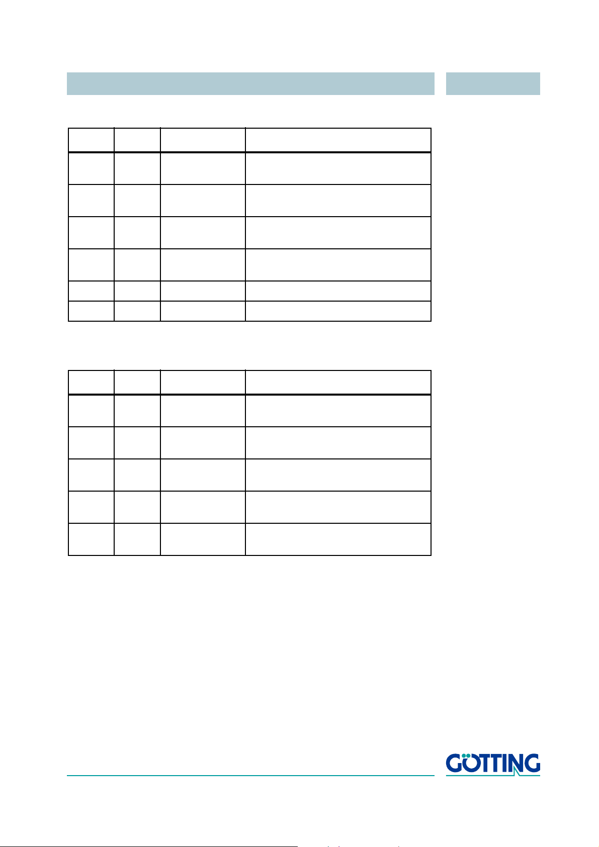
4.2.3.2.4 CAN Message Object 2 (Transmission Object)
Byte # Length Type Description
1,2 2 Byte unsigned short Voltage within the sum antenna gener-
ated by the Transponder
3,4 2 Byte signed short Voltage within the difference antenna
generated by the Transponder
5 1 Byte unsigned char Number of code readings during the
last valid Transponder crossing
6 1 Byte unsigned char Operational voltage for the Antenna
[100 mV]
7 1 Byte unsigned char Power consumption [10 mA]
8 1 Byte signed char temperature within the antenna [oC]
Tab le 6 Structure of the CAN Message Object 2
4.2.3.2.5 CAN Message Object 3 (Transmission Object)
Byte # Length Type Description
1,2 2 Byte unsigned short System status information according to
Table 3 on page 20
3,4 2 Byte unsigned short the lower 16 Bit of the Transponder
code
5,6 2 Byte unsigned short Voltage of the frame antenna gener-
ated by the Transponder [in units]
7 1 Byte unsigned char Number of code readings during the
last valid Transponder crossing
8 1 Byte unsigned char Number of code reading errors during
the last valid Transponder crossing
Tab le 7 Structure of the CAN Message Object 3
English, Revision 04, Date: 19.01.2015 26
Page 27
Components and Operation HG 98860ZA
4.2.3.2.6 CAN Message Object 4 (Reception Object)
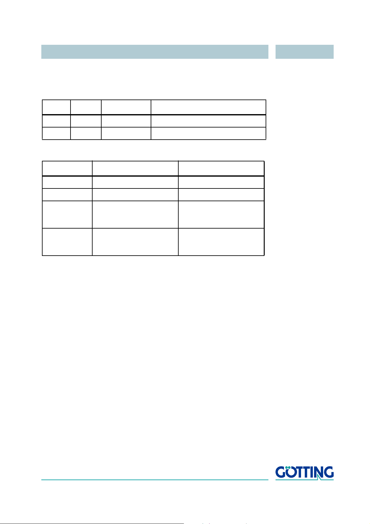
It is possible to send commands to the antenna. For this it is necessary to send a Message Object with the same address as Message Object 1 and a length of 6 bytes.
Byte # Length Type Description
1,2 2 Byte Unsigned short Command (see Table 9 below)
3,4,5,6 4 Byte Unsigned long Parameter (see Table 9 below)
Tab le 8 Structure of the CAN Message Object 4
Command Meaning Parameter
0000
0001
0002
16
16
16
No command —
Tune antenna once —
Set tuning value Tuning value
0000.000116 to
0004
16
0000.0010
Set position level Positioning level
16
0000.000016 to
0000.03E8
Tab le 9 Coding of commands
4.2.3.3 Positioning Pulse
The digital positioning output indicates the antenna center crossing in direction of travel. Its duration can be set within a millisecond pattern. Furthermore it is possible to limit
it to one pulse per crossing.
It is possible to ’freeze’ the content of the serial telegrams at the time of the positioning
pulse for an adjustable number of telegrams (refer to section
on page 35 and 5.3.2.5 „C(A)N-Parameters“ on page 39).
4.2.3.4 Analysis Interface
This interface (pin „R“ of the connection socket, see Table 1 on page 17) enables recording important system data independently of the serial data traffic. The interface
parameters are:
16
5.3.2.2 „(S)erial Output“
57600 Baud, 8 Data bit, no parity
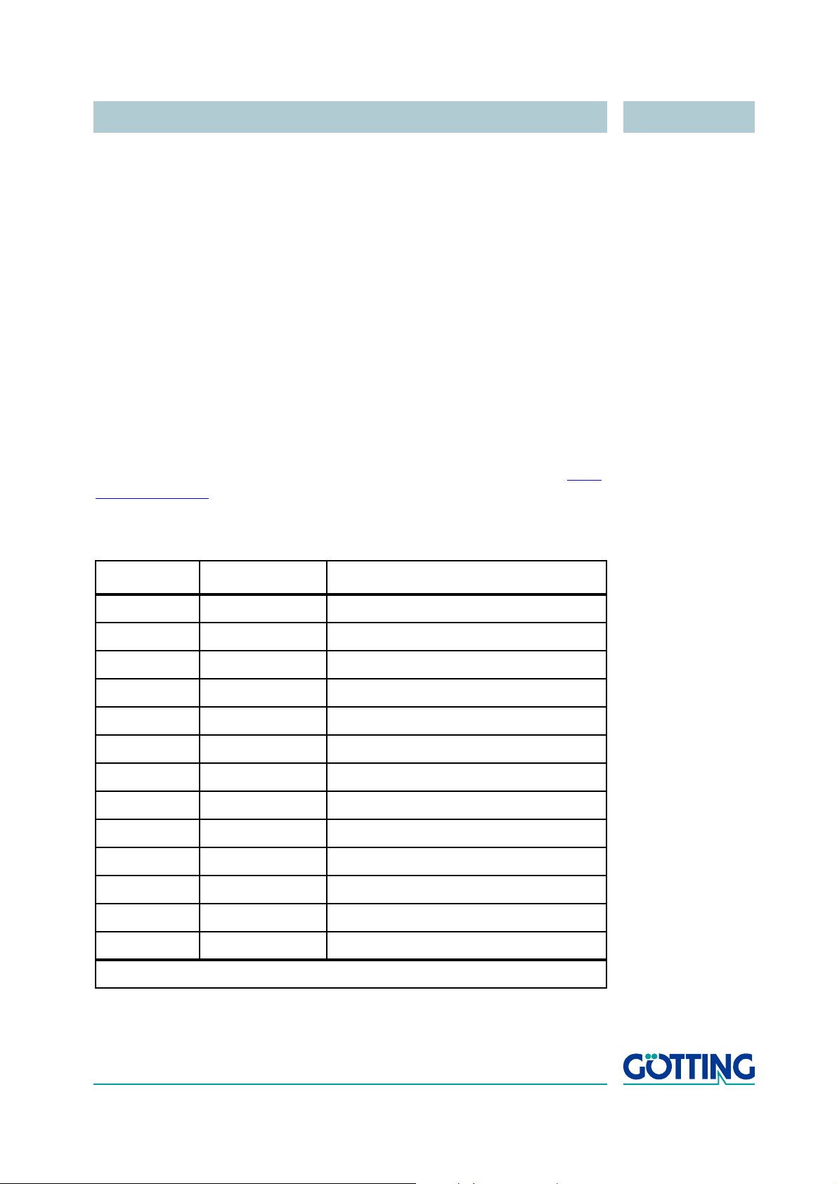
The following values are output as ASCII characters, separated by commas. Each line
is terminated with CR LF.
- Code (decimal)
- Sum voltage (decimal)
- Dif voltage (decimal)
- Deviation X (mm)
English, Revision 04, Date: 19.01.2015 27
Page 28
Components and Operation HG 98860ZA
- Deviation Y (mm)
- TRANS_IN_FIELD (Bit)
- ESTIMATE (Bit)
- COILSEL (Bit)
It is, for example, possible to record this data with the terminal program Hyperterm,
save it as *.csv file and interpret it accordingly (refer to section
4.2.4 Software Download
If necessary, the Antennas may be updated via the serial interface. Please refer to section 5.4 „Software Update (Antenna Software)“ on page 44.
4.2.5 Connection Cable HG 09240DB
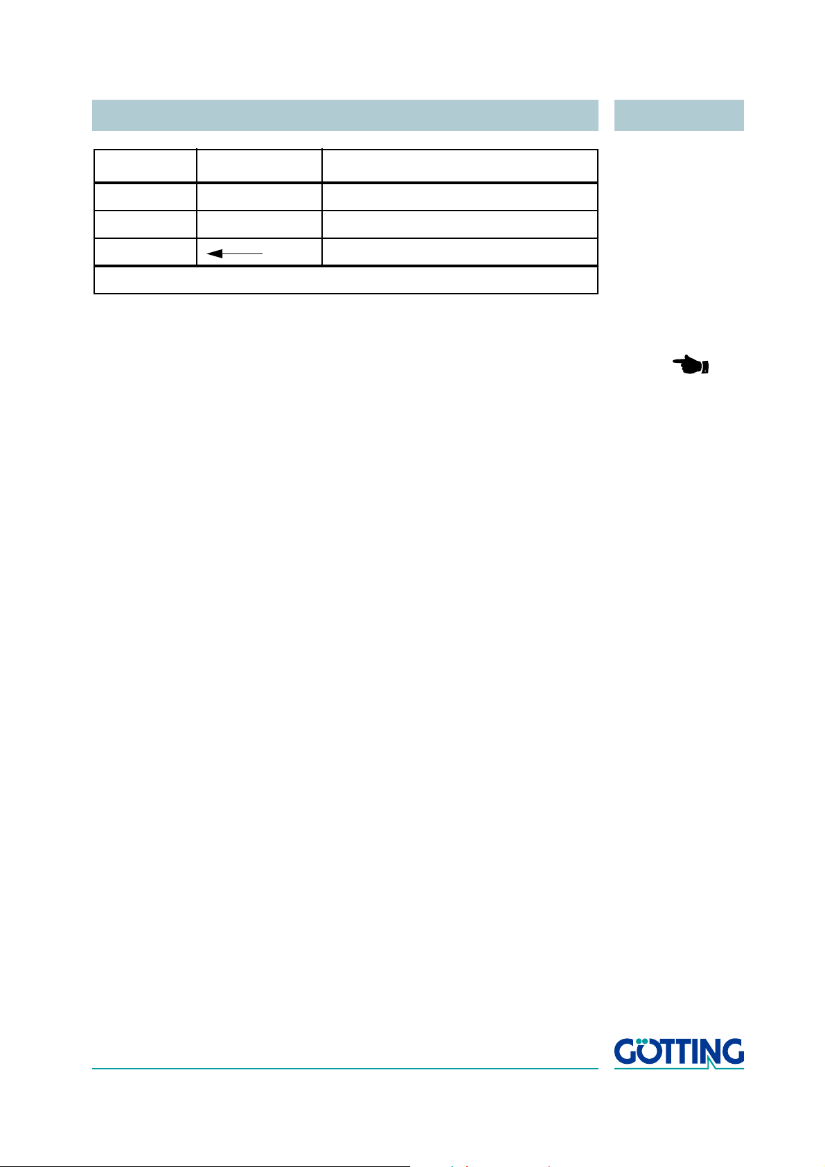
The connection cable included in the scope of supply will be fitted with the corresponding connector on the antenna side, while the vehicle side will be open. The necessary length (max. 20 m) is to be stated in the purchase order. The cable is a
HELUKABEL F-C-PURÖ-JZ grey, 12x 1
www.helukabel.de/). The cable consists of a shield, 11 black wires of 1 mm² (num-
bered 1 through 11) and one green-and-yellow wire. The shield is connected to the
connector housing. The pin allocation is as follows:
mm² (for further information refer to http://
5.3.2.6 on page 40).
Contact Wire no. / Color Allocation
A 1 +24 V (antenna)
B 2 GND (antenna)
C — n. c.
D — n. c.
E 5 Rx 422+ *
F 3 Rx 422- *
G 7 Tx 422+ *
H 4 Tx 422- *
J 9 +20 mA Positioning connection
K 10 -20 mA Positioning connection
L 6 CAN_H
M 8 CAN_L
N green-yellow signal ground
* = Rx and Tx relative to the antenna.
Table 10 Connection cable pin allocation (part 1 of 2)
English, Revision 04, Date: 19.01.2015 28
Page 29
Components and Operation HG 98860ZA
Contact Wire no. / Color Allocation
P — n. c.
R 11 RS 232 TxD for data logging
S Shield
* = Rx and Tx relative to the antenna.
Table 10 Connection cable pin allocation (part 2 of 2)
NOTE! In order to achieve cable lengths of up to 100 m (for RS 422,
CAN), it is essential to use a cable with shielded twisted pairs!
English, Revision 04, Date: 19.01.2015 29
Page 30
Software HG 98860ZA
5 Software
The system can be configured via an antenna internal software. To enter the program,
you have to connect the serial interface of an ordinary PC to the serial interface of the
antenna. For the antenna type HG
HW
CAB00113 (see section 5.4.2 on page 44) or an interface converter RS 422 ->
RS 232 is necessary. Once all the connections have been set up, start a terminal program on the PC.
NOTE! The interface converter is not part of the system´s scope of sup-
ply! However, it is available from several well-known distributors,
as e. g. RS components
refer to the section „Industrial Interface Converters“ of the RS
components catalogue.
5.1 Terminal Program
In the following we will refer to the program HyperTerminal® (Hypertrm.exe), which
was part of the scope of supply of Microsoft® Windows® up until version XP. We prefer
the use of this program because it is easily available for many users and, due to the
supplied configuration files, it is very easy to use.
98860ZA either the Götting adapter cable
http://www.rs-components.com/. Please
Nevertheless, any other terminal program can be utilized, provided that it enables
VT52 emulation. If you should use a different program, please read its documentation
carefully and adjust it to the values given in section
5.2 on page 30.
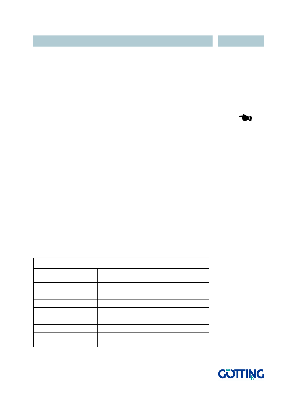
5.2 Parameter Settings
Depending upon what you want to do (starting the monitor program or the software update), different parameters are necessary. If you are using HyperTerminal, you do not
need to enter these settings and can go straight on to section
Terminal settings monitor program (refer to section 5.3)
baud rate 19200 or 38400 Bd
depending on the system configuration
terminal emulation VT52
parity even
data bits 8
stop bits 1
character delay 1 ms
line delay 0 ms
PC interface (port) COM1
can alter depending on the PC (see below)
5.3 on page 31.
Tab le 11 Terminal settings for the monitor program
English, Revision 04, Date: 19.01.2015 30
Page 31
Software HG 98860ZA
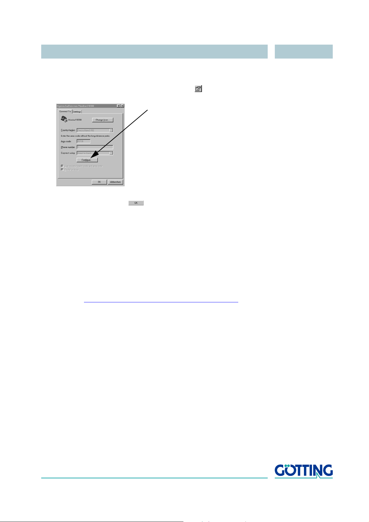
If you are using a different port than COM1 with HyperTerminal, then adjust the port as
follows:
1. Select Properties from the menu file (or click the Icon ). The following window
appears:
2. Choose the direct connection to the respective port via the submenu direct
connection. Confirm with
while exiting HyperTerminal.
5.3 System Monitor
. Save the altered values if you are asked for it
In monitor mode the system can be configured using the corresponding menu. To use
the monitor mode you need to know which protocol is set in your antenna.
5.3.1 How to start the monitor program
The command for switching to monitor mode should be input directly via a PC. For the
startup, a set of configuration files is necessary (small text files and HyperTerminal
configuration files). These files are accessible always in the latest version from our in
ternet server at http://www.goetting-agv.com/components/transponderconf for down-
load. On that page you‘ll find the individual text files.
Start your terminal program. If you are using HyperTerminal (section 5.1) it can now be
started directly by double clicking the respective *.ht file (Monitor19200.ht at
19200
Bd and Monitor38400.ht at 38400 Bd). If necessary, adapt the COM-port
(see section
Following the switching on and a minimum period of 10 (respectively 26) seconds, you
may transfer the required *.txt file from the disc using the terminal program. The follow
ing four files are on the disc:
1. Mon3964r.txt
Transfer if the system is adjusted to procedure 3964R with “HighByte first“. The
file contains the characters: 0x02 0x4D 0x4F 0x4E 0x49 0x10 0x03
0x16 in hexa-decimal notation
5.2).
-
-
2. Mon6439r.txt
Transfer if the system is adjusted to procedure 3964R with “LowByte first“. The
file contains the characters: 0x02 0x4F 0x4D 0x49 0x4E 0x10 0x03
0x16in hexa-decimal notation
English, Revision 04, Date: 19.01.2015 31
Page 32
Software HG 98860ZA
3. Montrans.txt
Transfer if the system is adjusted to procedure Transparent with “HighByte
first“. The file contains the characters: 0x3D 0x4D 0x4F 0x4E 0x49
0x38 in hexa-decimal notation.
4. Transmon.txt
Transfer if the system is adjusted to procedure Transparent with “LowByte
first“. The file contains the characters: 0x3D 0x4F 0x4D 0x49 0x4E
0x38in hexa-decimal notation
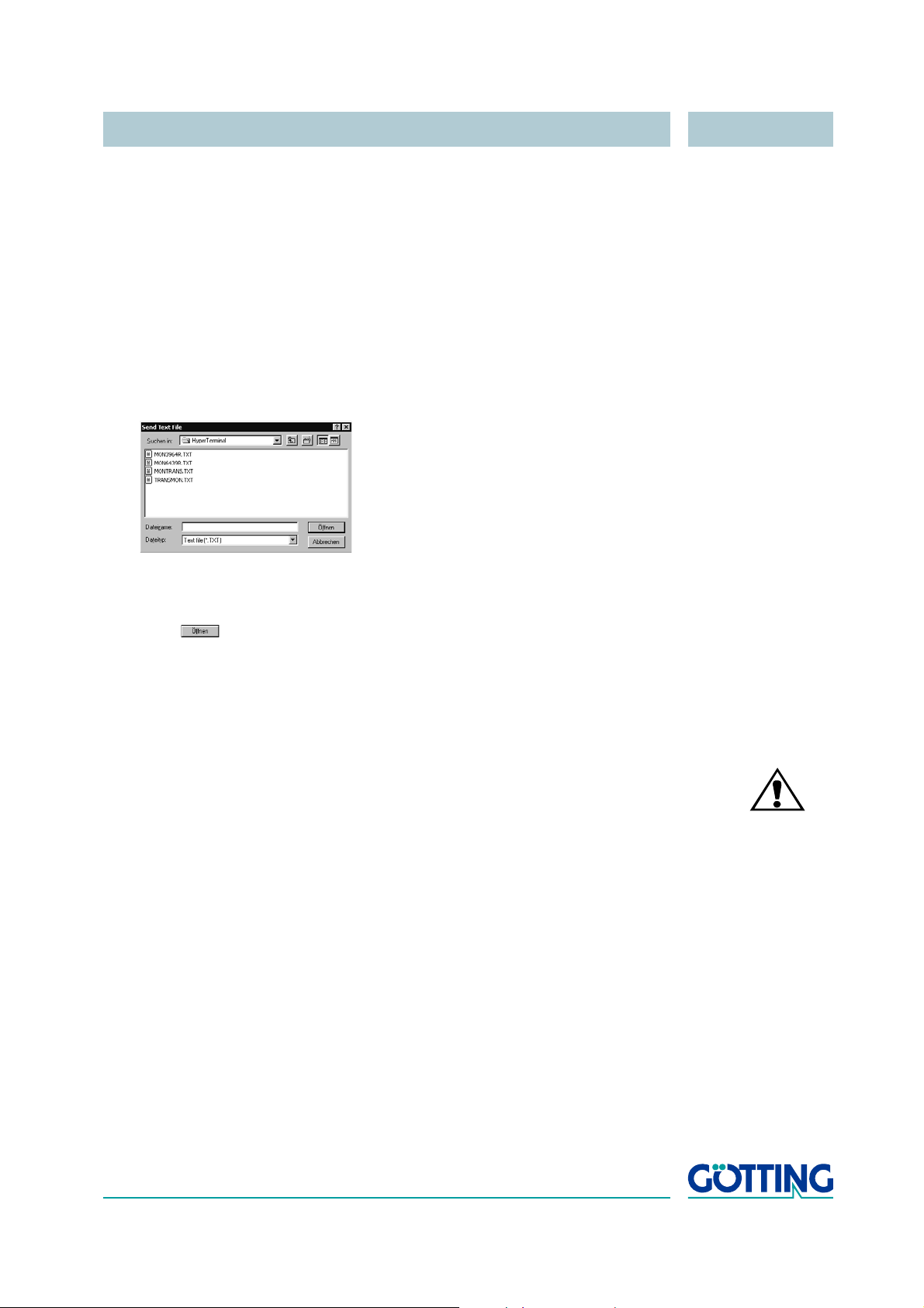
Using HyperTerminal the file is transferred as follows:
1. Select Send Text file in the menu Transfer. The following window will
appear:
2. Switch to disc drive (in our example, the files are located on the hard disc) and
select the respective *.txt file.
3. Click . The file will be transferred and (once the corresponding file has
been selected) the monitor program will be started. The menus will then appear
directly within the HyperTerminal Window. First, the main menu from
on page 33 will appear.
Figure 17
5.3.2 How to work with the monitor program
ATT ENTION! Effect only alterations on values for the system interface as posi-
tioning accuracy will decrease if the calculation coefficients are
altered!
Any change to the interface parameters will be only activated after a system reset (turn
antenna off and on). Afterwards it may be necessary to use a different file from the four
given *.txt documents to start the monitor!
After the transfer of the *.txt file (refer to section 5.3.1) the monitor program starts with
the main menu. If it does not, you have either based your settings on a wrong system
configuration, or you are using a different terminal emulation and did not adjust the
character delay to 1 ms, or you did not wait at least 10
tenna.
s (26 s) after activating the An-
English, Revision 04, Date: 19.01.2015 32
Page 33
Software HG 98860ZA
S:0005 D:+005 D_Y:+32767 D_X:+32767 Code: 0000 Read: 0: N: 1
Frx[/Hz]:61280 Ftx[/Hz]:127990 CSEL: 1
U[/mV]:24200 I[/mA]: 340 T[Grd.C]:+14 S_MA: 8002 S_SL: 0000 Noise 0
(S)erial Output
(T)ime & Code
(F)requency & Antenna tuning
Basic C(A)N-Parameters
CA(N)-Open-Parameters
(D)isplay Systemstatus
Cs(v) [38,4 KB Code,Us,Ud,X,Y,Tr,Co,Pos,N,E,Cnt<crlf>] (abort with <a>)
display Histogram: (X) AbsValues, (-)SignedValues
display Histogram: (Y) AbsValues, (+)SignedValues
[L]oad Userparameters to EEProm
[U]pdate Firmware
(1) Import User Parameter from Host to Antenna
(2) Export User Parameter from Antenna to Host
P(r)int Parameters
{3} Service Menu
Software Version 98860MA1.02 / 15.NOV.2013 Serial Number: 123456
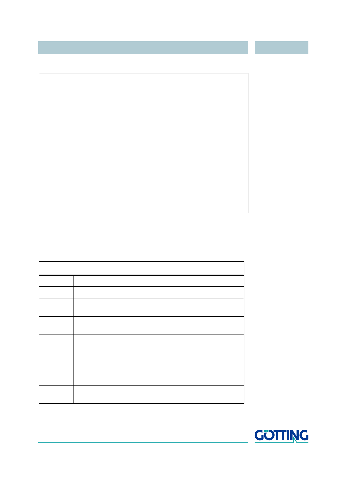
5.3.2.1 Main menu
Figure 17 Main menu of the monitor program
Each of the monitor menu windows contains important system variables in the upper
four lines (also refer to
Table 12), as they also appear in the output telegram (described
in section 4.2.3.1.1 on page 18). The bottom line on the screen contains possible status messages, e. g. if allowed values ranges were not obeyed during input.
Description of the system variables
S Measured voltage of the sum coil in units (max. 1023)
D Measured voltage of the positioning coil in units (max. 1023)
D_Y [mm] Transponder position rectangular to the direction of travel in milli-
meters (max. ±750, 32767 when position invalid)
D_X [mm] Transponder position in direction of travel in millimeters
(max.
±300, 32767 when position invalid)
Code The 32 data bits of the Transponder in hexa decimal coding. The
code is recorded as soon as voltage S exceeds the Threshold
for Positioning (refer to
Figure 20 on page 37)
Read The number of code readings per Transponder crossing (max.
N Number of reading errors per Transponder crossing. This value
Table 12 Description of system variables (monitor program) (part 1 of 2)
255). This value is being stored until a new Transponder code
has been detected. May be deleted by noise
is stored until a new Transponder has been detected
English, Revision 04, Date: 19.01.2015 33
Page 34

Software HG 98860ZA
Description of the system variables
Frx [Hz]
and
Ftx
[Hz]
Display of important system frequencies for transmission and
reception. These frequencies are permanently monitored and
are included in the system status word E (see
below)
CSEL Determins from which channel the code is detected
U [mV] Supply voltage of the processor board measured with an accu-
racy of 100 mV. This voltage is, due to various safety measures,
always a little lower than the connected overall supply voltage
I [mA] Current consumption of the positioning unit measured with an
accuracy of 10
mA
T [Grd.C] Average temperature measured in steps of 5o C
S_MA Hexadecimal system status from master. The description of the
individual bits is included in
Table 4 „List of the system com-
mands“ on page 22
S_SL Hexadecimal system status from slave.
Noise Output of one counter:
- Whenever the sum voltage S exceeds the Threshold for
Decoding the counter is increase every 8
ms until it has
reached the value 1.000.
- Whenever S falls under this threshold, the counter counts
backwards until it has reached 0 again. When a code is
decoded, the counter is immediately set to 0.
This mechanism checks whether a Transponder or a foreign signal is received. Every time this counter exceed an adjustable
value (refer to section
5.3.2.3 „(T)ime & Code“ on page 37), the
system status bit RX_NOISE is set.
Table 12 Description of system variables (monitor program) (part 2 of 2)
Further menus are activated via input of the (characters in brackets). Before altered
values are transferred into the permanent memory, the pass word 815 has to be en
tered by first entering . This prevents unwanted alterations of values. With the val-
ues are saved after alteration and input of the password.
Input of enables reading the description of a possibly occurring system status message. If the procedure is „transparent or „3964r“ input of will exit this menu.
The following section describes the submenus
- ()erial Output (section 5.3.2.2 on page 35)
- ()ime & code (section 5.3.2.3 on page 37)
- ()requency & Antenna tuning (section 5.3.2.4 on page 38)
- Basic C()N Parameters (section 5.3.2.5 on page 39)
- CA()-Open-Parameters. This interface is part of another documentation.
-
English, Revision 04, Date: 19.01.2015 34
Page 35

Software HG 98860ZA
S:0007 D:-007 D_Y:+32767 Code: 00000000 Read: 0: N: 1
Frx[/Hz]:66760 Ftx[/Hz]:127990 Csel:1
U[/mV]:23100 I[/mA]: 530 T[Grd.C]:+24 E: 0002 Noise 0
(B)audrate: 19200
(O)rder of Data Transfer (0= HiByte first): 0
(T)elegram Content Mask [0..1FFF]: 00001fff
(D)isplay Telegram Content
(C)har-Delaytime [1..220ms]: 220
(P)rocedure Transparent
Co(n)tinous Telegrams 1
(S)erial Data Period [4.500mS]: 8
(F)reeze Values for n Telegrams:[0..10]: 0
(Q)uit Menue
- Cs() (section 5.3.2.6 on page 40)
- display Histogram (/) (section 5.3.2.7 on page 41)
- display Histogram (/) (section 5.3.2.8 on page 42)
- ()oad Userparameters to EEProm (section 5.3.2.9 on page 43)
- () Import / () Export User Parameter (section 5.3.2.11 on page 43) and
- ()pdate Firmware (section 5.3.2.10 on page 43) and
- P()int Parameters (section 5.3.2.12 on page 43).
5.3.2.2 (S)erial Output
Any changes effected to this sub menu are activated only after a system reset (switching the antenna off and on again). Depending on the alterations made, it may become
necessary to use a different baud rate / different text document for the startup of the
monitor (section
5.3.1 on page 31).
Figure 18 Menu: (S)erial Output
Pressing switches between 19200 and 38400 Bd. Pressing selects between
high byte first and high byte last. When using this system together with a Siemens PLC
it is essential, that this parameter is 0 (High Byte first).
enables influencing the structure of the output telegram. The telegram length is set
automatically.
According to the values given in Table 2 „Data words in a telegram with 21 byte length“
on page 19, it is possible to set the customized contents of the telegram using
hexadecimal addition. The parameter sequence cannot be influenced. It is always the
same sequence as shown in the table!
English, Revision 04, Date: 19.01.2015 35
Page 36

Software HG 98860ZA
S:0005 D:+005 D_Y:+32767 D_X:+32767 Code: 0000 Read: 0: N: 1
Frx[/Hz]:61280 Ftx[/Hz]:127990 CSEL: 1
U[/mV]:24200 I[/mA]: 340 T[Grd.C]:+19 S_MA: 8000 S_SL: 0000 Noise 0
STX 1 Bytes from Position: 1
Delta_Y 2 Bytes from Position: 2
Delta_X 2 Bytes from Position: 4
CODE 2 Bytes from Position: 6
Usum 2 Bytes from Position: 8
Udif 2 Bytes from Position: 10
Vcc 1 Bytes from Position: 12
Current 1 Bytes from Position: 13
Temp. 1 Bytes from Position: 14
CodesRd 1 Bytes from Position: 15
Rx-Freq 2 Bytes from Position: 16
Tx-Freq 2 Bytes from Position: 18
STATUS 2 Bytes from Position: 20
(esc) to quit
Example Only the Displacements X and Y, the Code and the System
Status are to be output.
Add, according to the table the values 0x0000.0001,
0x0000.0002, 0x0000.0004, 0x0000.0008 and 0x0000.1000. The
result is 0x0000.100F. Therefore the input for the “(
Content Mask“ is 0x100F.
Using “()isplay Telegram Content“ it is possible to check the review telegram (also
refer to
Figure 19). The shown case has a mask value of 0x0000.1fff. Pressing any key
generates the return to menu Serial Output.
)elegram
Figure 19 Menu: „(D)isplay Telegram Content“
Parameter „()har Delaytime“ is the so-called Character Delay Time for procedure
3964R (refer to appendix, section
A „Procedure 3964R“ on page 50) and the timeout
time for incoming characters transparent mode (refer to appendix, section B „Procedure „transparent““ on page 51).
Pressing generates the selection of the corresponding telegram procedure — 3964R
or transparent. For procedure 3964R it is also possible to set the acknowledgement
delay time.
enables choosing between the permanent output according to the set erial
Data Period (1), or output only whenever a Transponder is decoded within the read
ing range (0).
enables ’freezing’ the serial output for 0 to 10 telegrams, i. e. the values at the time
of the positioning pulse output are preserved.
English, Revision 04, Date: 19.01.2015 36
-
Page 37

Software HG 98860ZA
S:0006 D:+005 D_Y:+32767 D_X:+32767 Code: 0000 Read: 0: N: 1
Frx[/Hz]:61280 Ftx[/Hz]:127990 CSEL: 1
U[/mV]:24200 I[/mA]: 350 T[Grd.C]:+19 S_MA: 8002 S_SL: 0000 Noise 0
(B)Level to Noise Error [0..1000]: 1000
(H)igh-Nibble of RW-Code [0..F,>F]: 10
(N)umber of equal Codes [0..15]: 1
(T)hreshold Decoding-X/Calculation [20.1023]: 256
Thr(e)shold /Calculation-Y [20.1023]: 400
PosiPulse (a)fter Decoding 1
(L)evel for Positioning [20.1023]: 500
(P)osi-Pulse Time [n*1ms]: 100
(O)ne Positioning Pulse per Crossing 0
(X) Timed Positioning Pulse 1
Th(r)eshold MAX-Detection-X [10.1023]: 400
Thre(s)hold MAX-Detection-Y [10.1023]: 400
(esc)to quit
5.3.2.3 (T)ime & Code
This menu offers the option setting the values for the Transponder decoding, the position calculation and the positioning pulse.
Figure 20 Menu: (T)ime & Code
enables setting the threshold for generating the bit RX_NOISE of the system status
word as described in
As the Trovan technology secures the code transmission only via a simple parity
check, two additional security strategies were implemented:
1. It is possible to verify the four highest bits via a preset value (0-F). enables
setting this value, which then has to be programmed into the transponders
together with the code. For entries larger F, this verification is switched off.
2. It is possible to choose the number of codes to be compared between 0 and 15
by pressing
input of 1 generates the comparison of the received code with the very last code
received just before this one, etc. Note, that this procedure reduces the maxi
mum crossing speed, because the necessary transmission time increases
accordingly with (n+1) x 8
With it is possible to determine the voltage threshold S at which the decoding is
started, in order to suppress decoding cycles with a too weak signal, and the X-posi
tion calculation generated.
With it is possible to determine the voltage threshold S at which the Y-position calculation is generated.
releases the output of a positioning pulse only after the decoding of a Transponder.
In an interference laden environment this will avoid false positioning pulses. For high
speed crossing this item should be set to 0.
English, Revision 04, Date: 19.01.2015 37
Table 12 on page 33 under ’Noise’.
. Input of 0 generates the immediate output of the received code,
ms.
-
-
Page 38

Software HG 98860ZA
S:0006 D:+005 D_Y:+32767 D_X:+32767 Code: 0000 Read: 0: N: 1
Frx[/Hz]:61280 Ftx[/Hz]:127990 CSEL: 1
U[/mV]:24200 I[/mA]: 270 T[Grd.C]:+19 S_MA: 0002 S_SL: 0000 Noise 0
(R)x_Frequency [/Hz]: 1575000 ( 61250 Hz)
A(u)to-Tune 0
(A)ntenna-Tuning [0..15,+,-]: 15
switch (T)ransmitter: 1
(esc)to quit
F
rx
4FZF64 kHz– +-
B
2
--- -
=
enables setting the voltage value S which is the threshold for releasing the position-
ing pulse output in order eliminate false statements due to antenna side lopes.
The duration of the positioning pulse is adjustable by pressing within a 1 ms pat-
tern. With it is possible to set whether with each crossing of the center axis of the
Antenna, a positioning pulse is to be generated (e.
ment directly above a Transponder). If not, only one pulse per Transponder crossing
is output. For a re-newed triggering it would then be essential that the voltage S falls
again under the Threshold for Calculation-Positioning (refer to section
5.3.2.3 on page 37).
With you can choose whether the Posi Pulse and its corresponding bit are turned
off in the system status after the time persiod set with
below the threshold set with
.
enables setting the the threshold value which has to be succeeded in order to ac-
tivate the use of the measured voltages in X direction for the calculation. does the
same for the Y direction. The actual threshold value is determined by the maximum of
a scan cycle minus the input value.
5.3.2.4 (F)requency & Antenna Tuning
g. during a back-and-forth move-
or after the voltage S has fallen
Figure 21 Menu: (F)requency & Antenna Tuning
The receiver frequency „()x“ is calculated with FZF = 455 kHz and the bandwidth
B = 5.5
Figure 22 Formula: Calculation of the receiver frequency
As this is a SSB-reception, according to the above mentioned formula the upper sideband should be set to 1553000 Hz and the lower sideband to 1575000 Hz.
English, Revision 04, Date: 19.01.2015 38
kHz according to the following formula:
Page 39

Software HG 98860ZA
S:0006 D:+005 D_Y:+32767 D_X:+32767 Code: 0000 Read: 0: N: 1
Frx[/Hz]:61280 Ftx[/Hz]:127990 CSEL: 1
U[/mV]:24200 I[/mA]: 270 T[Grd.C]:+19 S_MA: 0000 S_SL: 0000 Noise 0
SR = 00: NO ERROR / / / /
(C)AN active NO
E(X)tended CAN STANDARD
(I)dentifier: TX [0..2047]: 10
(A)-Identifier: TX [0..2047]: 0
(D)-Identifier: TX [0..2047]: 0
CAN-(B)aud [20,50,125,250,500,1000 kB]: 1000.0
or
B(R)P Baudrate Prescaler [0..63]: 0
(S)JW Sync Jump Width [0..3]: 0
Tseg(1) [2..15]: 6
Tseg(2) [1..7]: 1
resulting sample point: 70 %
(P)eriod [4.500mS]: 8
Co(n)tinous Telegrams 1
CAN on Re(m)ote Request 0
(F)reeze Values for n Telegrams [0..20]: 0
(esc) to quit
With or with the or keys you may tune the transmitting antenna by switching
the power consumption to max. (resulting in the largest reception range).
switching the transmitter on (1) or off (0) for control reasons.
is automatically set to
1 upon leaving the monitor.
enables activating auto tuning. Following each system switch on, the transmitter cy-
cle is retuned. This procedure takes approx. 16 sec. After that, every 10 sec. the tuning is re-checked (as long as there is no transponder within the field) and re-tuned if
necessary.
5.3.2.5 C(A)N-Parameters
This menu enables setting the various CAN Bus parameters. Before being able to use
the CAN bus interface it is essential to activate it by pressing
.
enables
Figure 23 Menu: C(A)N-Parameters
Entering enables the generation of telegrams either as standard frames according
to CAN2.0A or as extended frames according to CAN2.0B. Correspondingly it is pos
sible to either set the Identifier (CAN address) as 11 bit value (0-2047) or as 29 bit
value (0-536870911).
The identifier selectable under corresponds to the transmitted frames for the Message Object 1 (refer to Table 5 on page 25). The identifier selectable under refers
to the Message Object 2 (refer to Table 6 on page 26), refers to the Message Object
3 (refer to Table 7 on page 26). Input of 0 deactivates the corresponding Message Object.
With it is possible to change the CAN baudrate.
enables either the activation of a permanent output of the Clock for Sampling
which can be set by pressing
ated whenever a Transponder is within the reception range (0).
English, Revision 04, Date: 19.01.2015 39
(1), or the activation of an output that is only gener-
-
Page 40

Software HG 98860ZA
activates the remote operation. In this case (independent of the settings of Con-
tinuos Telegrams) telegrams are no longer generated, but only remote frames with
the corresponding address are answered.
offers the option to ’freeze’ the output for 0 to 20 telegrams, i. e. the values at the
time of the positioning pulse output are preserved.
The CAN status register is displayed in the uppermost line of the menu. This information may be used for simple diagnosis.
5.3.2.6 Cs(v)
For diagnosis, it is possible to start the output of the values Code, U
X-Pos, the states Transponder within range, Code OK, Positioning pulse
(also refer to
reading failures (N) and in addition a telegram counter in CSV format (Comma Separated Values; especially for processing text files with programs for table calculation).
Data output is carried out with 38.400
pressing any key. Following the pressing of a key, a reset is generated and the Antenna
is re-set to its original condition (not monitor mode) including the saved parameters.
The CSV output could e. g. be saved using the program HyperTerminal® (also refer to
section
Transmission and insert a file name (this file name should have the ending .csv, in
order to enable the table calculation program to automatically detect this file later).
Once the file has been recorded and closed under HyperTerminal®, it may be loaded
into a table calculation program (e.
Table 3 on page 20), number of code readings (Read), number of code
Bd, 8 bit and even parity, until it is terminated by
5.1 on page 30). To do so, use the function record text ... of menu
g. Microsoft® Excel®, Sun® StarCalc®, ...).
Sum
, U
, Y-Pos,
Dif
When opening the file, the table calculation program prompts various options. Select
the option that indicates that this file consists of comma separated values. Then the
data may be processed as diagrams or recorded as native table calculation file for
transmission.
English, Revision 04, Date: 19.01.2015 40
Page 41

Software HG 98860ZA
X_Histogram, press any key to return
> 1000.....................
> 900:.....................
> 800:.....................
> 700:.........OoOoo.......
> 600:.......oOOOOOOo......
> 500:o.....oOOOOOOOOOoo..O
> 400:OooOoOOOOOOOOOOOOO.OO
> 300:OOOOOOOOOOOOOOOOOOOOO
> 200:OOOOOOOOOOOOOOOOOOOOO
> 100:OOOOOOOOOOOOOOOOOOOOO
---+---+---+---+---+ 1 4 8 12 16 20
<<<<<<<M>>>>>
55 57 60
5
X_Histogram, press any key to return
> 900:.....................
> 800:.....................
> 700:..................... (M)ux [0..3,END = 9]
> 600:.....................
> 500:O...................O
> 400:O................O..O
> 300:OOOO.............OO.O
> 200:OOOO.............OO.O
> 100:OOOO.............OO.O
> 0:OOOO.............OO.O
>-100:....OOOOOOOOOOOOO..O.
>-200:....OOOOOOOOOOOOO..O.
>-300:....OOOOOOOOOOOOO..O.
>-400:.....OOOOOOOOOOOO..O.
>-500:.......OOOOOOOOO.....
>-600:........OOOOOO.......
>-700:.........O.O.........
>-800:.....................
>-900:.....................
<<<<<M>>>>>>>
55 59 59
4
5.3.2.7 Display (X)Histogram / (-)
This submenu displays the voltages induced by a Transponder in X-direction as absolute or signed values.
Figure 24 Menu: display (X)Histogram
Each column represents a location. A voltage value is represented by a row of Os.
Directly underneath the histogram, the values used for the respective position calculation are marked as <<<<M>>>>. Below this row, the calculated position with minimum, actual, and maximum values is displayed. Pressing any key returns to the main
menu.
NOTE! The (M)ux item is for test purposes only.
English, Revision 04, Date: 19.01.2015 41
Page 42

Software HG 98860ZA
Y_Histogram, press any key to return
> 1000........................................
> 900:........................................
> 800:...................oOOOo................
> 700:..................OOOOOOOo..............
> 600:.................OOOOOOOOOO.............
> 500:................OOOOOOOOOOOo............
> 400:..........o.o...OOOOOOOOOOOO....o.......
> 300:O..oooOOOOOOOO.OOOOOOOOOOOOOO.oOOOOoOo.O
> 200:OOOOOOOOOOOOOOoOOOOOOOOOOOOOO.OOOOOOOOoO
> 100:OOOOOOOOOOOOOOOOOOOOOOOOOOOOOOOOOOOOOOOO
---+---+---+---+---+---+---+---+---+---+
1 4 8 12 16 20 24 28 32 36 40
<<<<<<M>>>>>
101 103 105
4
Y_Histogram, press any key to return
> 900:........................................
> 800:........................................
> 700:........................................
> 600:........................................
> 500:........................................
> 400:........................................
> 300:....O.OOOOOOO..................OOOO..O.O
> 200:O.OOOOOOOOOOOO................OOOOOOOO.O
> 100:O.OOOOOOOOOOOO...............OOOOOOOOO.O
> 0:O.OOOOOOOOOOOO...............OOOOOOOOO.O
>-100:.O............OOOOOOOOOOOOOOO.........O.
>-200:...............OOOOOOOOOOOOOO...........
>-300:...............OOOOOOOOOOOOO............
>-400:................OOOOOOOOOOOO............
>-500:................OOOOOOOOOOO.............
>-600:.................OOOOOOOOOO.............
>-700:..................OOOOOOO...............
>-800:.....................OO.................
>-900:........................................
<<<<<<M>>>>>
101 103 105
4
5.3.2.8 Display (Y)Histogram / (+)
This submenu displays the voltages induced by a Transponder in Y-direction as absolute or signed values.
Figure 25 Menu: display (Y)Histogram
Each column represents a location. A voltage value is represented by a row of Os.
Directly underneath the histogram, the values used for the respective position calculation are marked as <<<<M>>>>.
Below this row, the calculated position with minimum, actual, and maximum values is
displayed. Pressing any key returns to the main menu.
English, Revision 04, Date: 19.01.2015 42
Page 43

Software HG 98860ZA
5.3.2.9 (L)oad values to EEProm
This submenu enables saving the parameters within a non-volatile memory once the
corresponding pass word has been entered. This is necessary in order to accept the
current changes as permanent settings.
5.3.2.10 (U)pdate Firmware
This submenu offers the option of a software update without having to disconnect and
re-connect the power supply. However, first it is necessary to install the update pro
gram as described in section 5.4 on page 44.
Then press within the main menu. A display with the following instructions will appear:
1. Close the COM-Port in Hyperterm using the icon .
2. Open the flash program ST10-Flasher 2.exe on your PC.
3. In ST10-Flasher 2.exe select the COM-Port, via which the antenna is cur-
rently connected to your PC.
4. Select the hex file to be programmed in ST10-Flasher 2.exe.
5. Now return to Hyperterm, re-connect the COM-Port via the icon and press
any key.
-
6. Within the next 20 sec. close the COM-Port using the icon , in Hyperterm,
switch back to ST10-Flasher 2.exe and start programming.
Once the programming is completed, return to Hyperterm, wait 10 sec. and re-connect the COM-Port (e. g. via the icon ). Then re-start the monitor mode (also refer
to section 5.3.1 on page 31).
5.3.2.11 Import (1) / export (2) User Parameter
It is possible to store or load all user parameters on or from a host via XMODEM file
transfer protocol:
- With you can import a parameter file from a host. After pressing that key you
should start an XMODEM file transfer within 50 seconds. When using Hyperterm
go to Transfer > Send file > XMODEM > File name. If the message Success is
displayed the file has been checked and loaded in the parameter RAM. To pre
serve the loaded values you should transfer them into the EEPROM (see 5.3.2.9
on page 43).
- With you can export user parameters to a host. After pressing that key you
should start an XMODEM file transfer. When using Hyperterm go to Transfer >
Receive file > XMODEM > Folder and then specify a file name. The file is trans
ferred and the message Success should be displayed.
5.3.2.12 P(r)int Parameters
Enables writing the system parameters into terminal program file (e. g. Hyperterm).
-
-
English, Revision 04, Date: 19.01.2015 43
Page 44

Software HG 98860ZA
5.4 Software Update (Antenna Software)
It is possible to update the software of the integrated interpreters via the serial interfaces using a portable PC. Following switching-on, the integrated download unit will
check for approx. 10 seconds whether a download is to be carried out. In case a
download is not generated, the units will return to the normal operating program. Data
received during this period of 10 seconds are examined for their validity.
NOTE! Only the update program described below may be used for the
software update!
5.4.1 Installation of the ST10-Flasher Program for Software Update
The program for the antenna software update is a 32-bit application for Microsoft®
Windows®. Upon request, this program is sent by email. Please address your re
quests to the email, phone, fax or mailing address given on the cover of this manual.
In order to install the program follow these steps:
1. Save the file ST10-Flasher2_setup.exe from the email to your hard disk,
then open the Windows Explorer and navigate to the file.
-
2. Double click ST10-Flasher2_setup.exe in order to start the installation pro-
cess. The installation routine allows you to adjust the installation path but usually
the defaults should work.
3. In order to start the software update program, use the Windows start menu,
where you can find
update of the antenna software as follows.
ST10-Flasher 2.exe. Then you can proceed with the
5.4.2 Software Update
While the software update is carried out, no other programs may occupy the used serial interface (COM-Port). Thus, terminate any such connections in your Terminal program (e. g. Hyperterm). Then connect the antenna to your PC. Unless you use the
Götting Adapter HW CAB00113 (see below) you have to use an appropriate interface
converter (not included in the antenna scope of supply; refer to the note on the top of
page 30). Then start the update program on your PC as described above.
The antenna HG 98860ZA contains 2 microprocessors. The master processor is programmed via the serial interface (see section 4.2.3.1 on page 18). The slave processor
can be controlled with the same program ST10-Flasher 2.exe. The connection to
this processor however is to be made via the slave interface (RS 232, see pins D and
P in
Table 1 on page 17). The connection parameters can be chosen in ST10-Flas-
her 2.exe. The Baudrate should not be set to values above 57600 Baud.
NOTE! The Programming-/Service-Adapter HW CAB00113 by Götting
can be used to connect the antenna socket to the PC. The
adapter cable is fitted with two DE9 sockets that are used alter
nately for the master and slave connection.
-
English, Revision 04, Date: 19.01.2015 44
Page 45
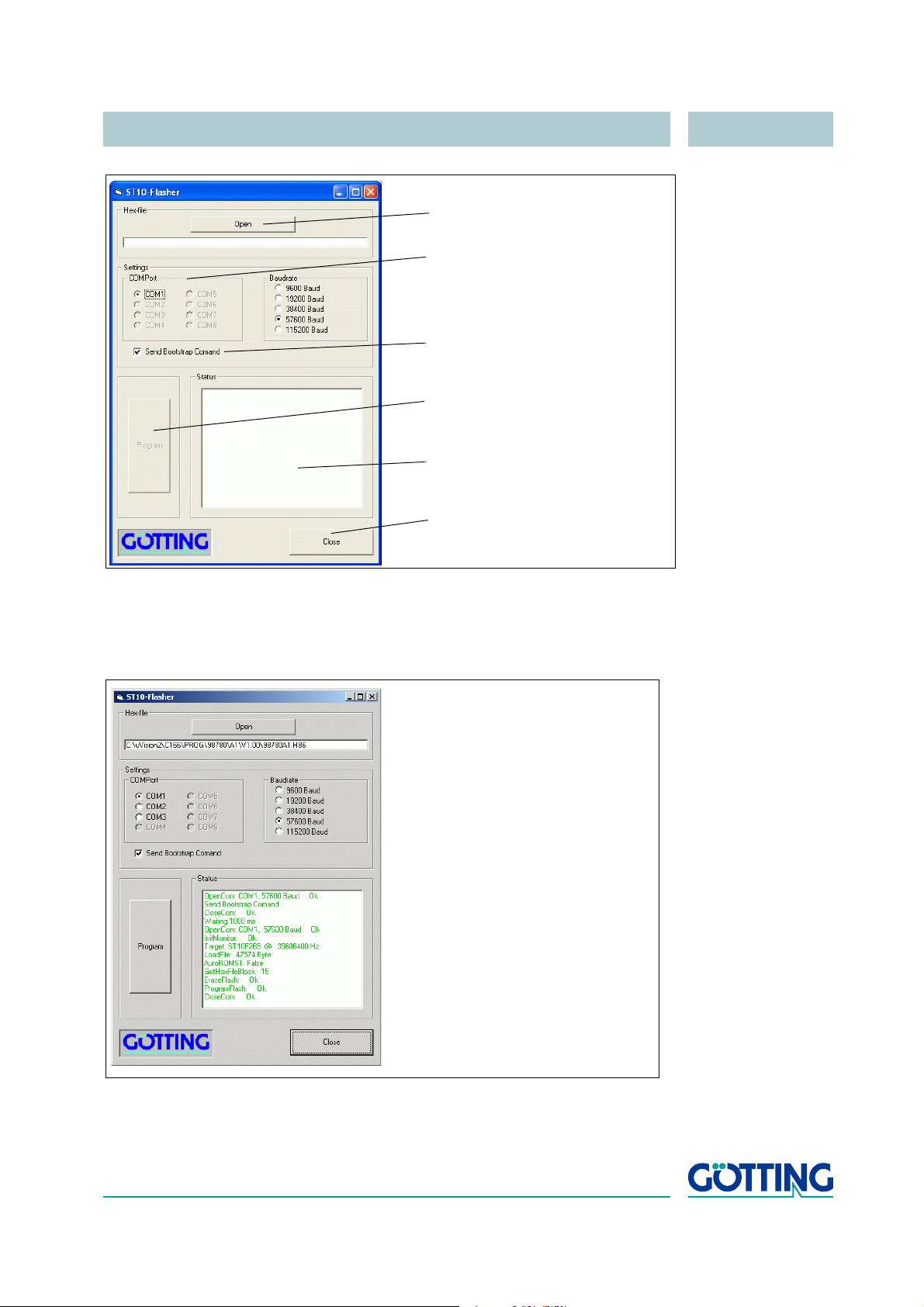
Software HG 98860ZA
2 Selection of the serial interface
1 Selection of the Hex file to be
5 Status messages
4 Start the programming procedure
6 Exit the program
transmitted
3 This option must always be
activated
and baud rate (max 57600 Baud)
If an error occurs during the transmission, red colored status messages are
shown. As long as green colored messages are output, the software update
is correct.
The last 2 messages of a normal update procedure are: ProgramFlash:
Ok and CloseCom: Ok
Figure 26 Update program: Operating Elements
Start the programming process by switching on the antenna and then click Program
within a period of 10 seconds afterwards. A device reset follows and after a short period of time, the file is being transmitted.
Figure 27 Update program: programming procedure
Once the programming process is completed, the program can be closed (close).
The interpreter is restarted automatically and uses the new program.
English, Revision 04, Date: 19.01.2015 45
Page 46

Maintenance HG 98860ZA
6 Maintenance
The system is largely maintenance free. Any maintenance is limited to:
- visual examination of the antennae (ensuring all screws, cables and plugs are
correctly fastened).
Document regularly the power consumption and power supply of each antenna. These
values can be obtained from any menu in the monitor program.
If necessary, effect an update of the system software as described above (section
5.3.2.10 on page 43 or 5.4 on page 44). Date and version of the current antenna software can be obtained from the main menu.
English, Revision 04, Date: 19.01.2015 46
Page 47

Trouble Shooting HG 98860ZA
7 Trouble Shooting
The following table contains a list of errors that might occur. For each error, a symptom
description is given. In the third column you will find a description of how to locate and
possibly correct the error.
If you should not be able to correct an occurring error, please use the table to locate
the source of the error as exactly as possible (nature of malfunction, at which point of
time did the error occur, etc.) before consulting us.
Error Possible cause Diagnosis/Correction
No system function
Even though a transponder is located within
reception range, all out
puts remain inactive
No contact is possible,
only unintelligible char
acters are sent.
Inaccurate values at low
temperature.
Output values are not
reproducible, lack of
accuracy
-
Power supply is not sufficient Measure the voltage at the respec-
tively labeled clamps.
-
1. RS 422 T+ (R+) exchanged with
RS 422 T- (R-) by mistake
2. Signal ground not connected, a
too high potential difference
between antenna and receiver.
3. Wrong setting of transfer parameters
4. Wrong procedure.
System needs a certain warm-up
time in order to operate at sufficient
accuracy in low ambient tempera
ture.
Radio interference Check value for S in the monitor
1. Check the connections
2. Connect signal ground
3. Choose only 19200 or
38400
Bd, 8 bit, even parity.
4. Choose the correct procedure
with the PC and the system
monitor.
Wait until the system has warmed
up (approx. 5 minutes at -20
-
mode. If these are over ca. 50,
there could be interference in the
range of 64
kHz.
o
C).
Transponders are
detected unreliably / no
reliable positioning
pulses
Table 13 Trouble shooting
English, Revision 04, Date: 19.01.2015 47
1. Interfering frequencies
2. The corresponding thresholds
(refer to
are not correctly set
Figure 20 on page 37)
1. refer to above paragraph
2. Carry out the commissioning as
described in section
10
3 on page
Page 48
Technical Data HG 98860ZA
8 Technical Data
8.1 Transmitter-Receiver Antenna
Antenna HG 98860ZA
Casing see Figure 13 on page 16
Weight approx. 36 kg
Effective antenna area 1500 x 600 mm (function range positioning)
Power supply antenna 24 V -20 % +50 %, max. 1.3 A @ 24 V
Operating temperature -25 to +50 oC
heat-up time 5 minutes
Mechanical stability 5 g 11 ms / 2 g 10 to 55 Hz
Metal free area see description for Figure 5 on page 8, and sec-
tion C on page 52
Protection IP 65
Cabling max. 20 m cable
Max. pass-over speed 10 m/s tested
Reading distance (distance transponder underside reading
antenna)
Nominal reading distance
Width of the active
Antenna reading area
Static positioning accuracy (Vx & Vy < 1 m/s)
Connection 16-pin Amphenol connector
Signal processing time 8 ms
output RS 422 / CAN The output requires 19200 or 38400 Bd. The tele-
Output positioning pulse 20 mA current source, potentially separated
150 to 350 mm (with transponder HG 70653)
200 to 250 mm (with HG 70653)
±750 mm (Y) x ±300 mm (X)
±15 mm @ nominal reading distance (with
HG
70653; also refer to section F on page 54)
gold-plated contacts
gram content may be configured. 3964R or “transparent“ selectable
Table 14 Technical Data Antenna HG 98860ZA
English, Revision 04, Date: 19.01.2015 48
Page 49
Technical Data HG 98860ZA
8.2 Connection Cable
Connection Cable HG 09240DB
Length according to purchase order, max. 20 m
Diameter approx. 10.9 mm
Type HELUKABEL F-C-PURÖ-JZ grey, 12x 1 mm²,
EMC preferred type, tear resistant, coolant resistant, Cu screened, without inner sheath
Weight: 262 kg/km
Cop. Weight: 187 kg/km
(also refer to http://www.helukabel.de/)
Table 15 Technical Data Connection Cable HG 09240DB
English, Revision 04, Date: 19.01.2015 49
Page 50
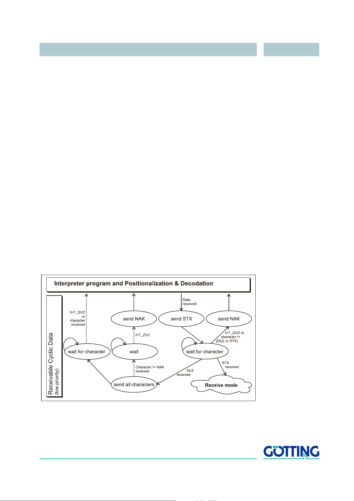
Appendix HG 98860ZA
(Figure
9Appendix
A Procedure 3964R
For the computer interconnection between antenna <—> SPS a 3964R-Protocol may be
used. As the antenna outputs data cyclical, this results in some simplifications during
implementation of the 3964R. The following diagrams describe the procedure.
The following settings need to be observed:
- Transponder system has lower priority
- Data transfer is set to 1 start bit, 8 Data bit, parity even, 1 stop bit, Baudrate
19200
Bd (default) or 38400 Bd.
A.1 Data direction antenna -> SPS
In this direction the antenna data is transmitted cyclically. The data sentence always
starts with an „=“-character (hex 0x3d). The cycle time is parameterizeable and should
take a complete part, or multiple thereof, of the transponder code´s transmission line.
In the present system, the duration for the transponder code transmission is 32
The minimum cycle duration depends upon the telegram length, the Baudrate and the
chosen telegram content.
ms.
In the diagram
T_ZVZ stands for the programmable character delay and
T_QVZ for the programmable acknowledgement delay.
Figure 28 Diagram procedure 3964R; antenna —> SPS
English, Revision 04, Date: 19.01.2015 50
Page 51
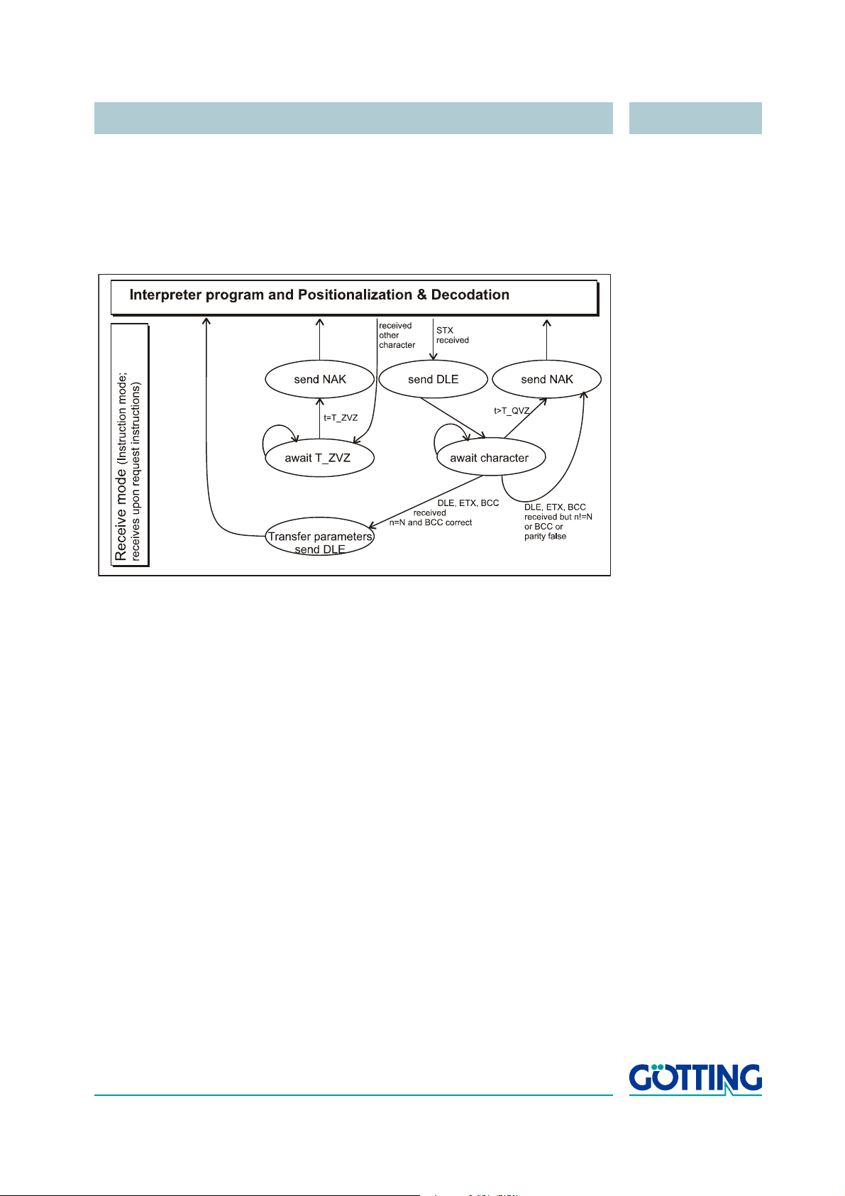
Appendix HG 98860ZA
A.2 Data direction SPS -> Antenna
In this direction commands are transmitted only when required (by now the command
for starting the monitor program is implemented; see section
overcome the frequent cyclical data output of the antenna, the 3964R of the antenna
has a lower priority (see
Figure 28).
4.2.3.1.2 on page 22). To
Figure 29 Diagram procedure 3964R; SPS —> antenna
B Procedure „transparent“
For the interconnection antenna <—> SPS a transparent protocol can be used. The following settings have to be observed for the data transmission:
- 1 start bit, 8 data bit, parity even, 1 stop bit, Baudrate 19200 Bd (default) or
38400
Bd.
B.1 Data direction antenna -> SPS
In this direction, cyclical antenna data is transmitted. The duration is parameterizeable, it should take an integral part or multiple of the transponder code transmission.
The minimum cycle duration depends upon the telegram length, the Baudrate and the
chosen telegram content.
The data sentence always starts with an „=“-character (hex 0x3d). Then the parameters chosen from the respective menu follow. The telegram is to be quit with an 8 bit
check sum over all characters. The characters are sent without delay.
B.2 Data direction SPS -> antenna
Commands are transmitted into this direction if necessary. Each command must start
with a „=“-character (hex 0x3d). The format of the commands is described in
„Possible system status messages“ on page 20. The telegram is to be quit with a 8 bit
Table 3
English, Revision 04, Date: 19.01.2015 51
Page 52
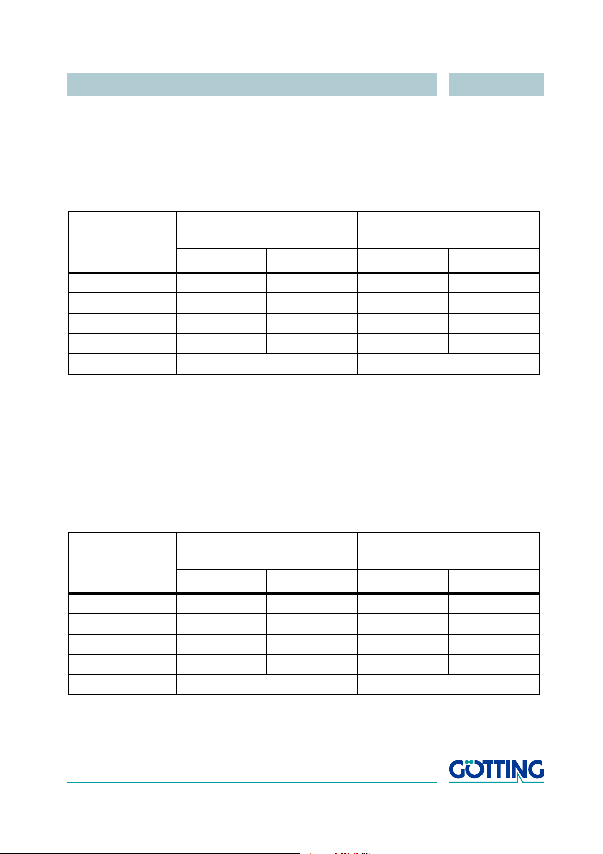
Appendix HG 98860ZA
check sum over all characters. The characters are sent without delay. The characters
must be received within the parameterizeable character delaytime. Otherwise the tele
gram will be chopped.
C Influence of a metal plate on the antenna
1 mm thickness of the plate
-
Distance
(metal <—> antenna)
[mm]
150 5 180 240 320
200 5 480 250 810
300 385 650 300 900
400 490 650 420 900
Table 16 Influence of metal on the antenna
Measurements have been carried out with a steel plate above the antenna in variable
distances. The transponder was positioned at nominal reading distance (250
derneath the antenna. Current consumption was retuned to maximum value, see section 5.3.2.4 on page 38. The measured displacement signal of the transponder is not
influenced through metal as long as the surface of the antenna is covered evenly.
Transponder HG 70653 @ 250 mm
[S /units]
without with retuning without with retuning
650 900
antenna current
[mA]
mm) un-
D Influence of a metal frame on the antenna
Size of frame: 1600 mm x 800 mm, 30 mm hollow profile, 1 mm wall thickness
Distance
(metal <—> antenna)
[mm]
150 215 520 290 800
200 340 540 350 830
300 510 585 580 880
400 595 605 840 900
Table 17 Influence of metal on the antenna
English, Revision 04, Date: 19.01.2015 52
Transponder HG 70653 @ 250 mm
[S /units]
without with retuning without with retuning
640 900
antenna current
[mA]
Page 53
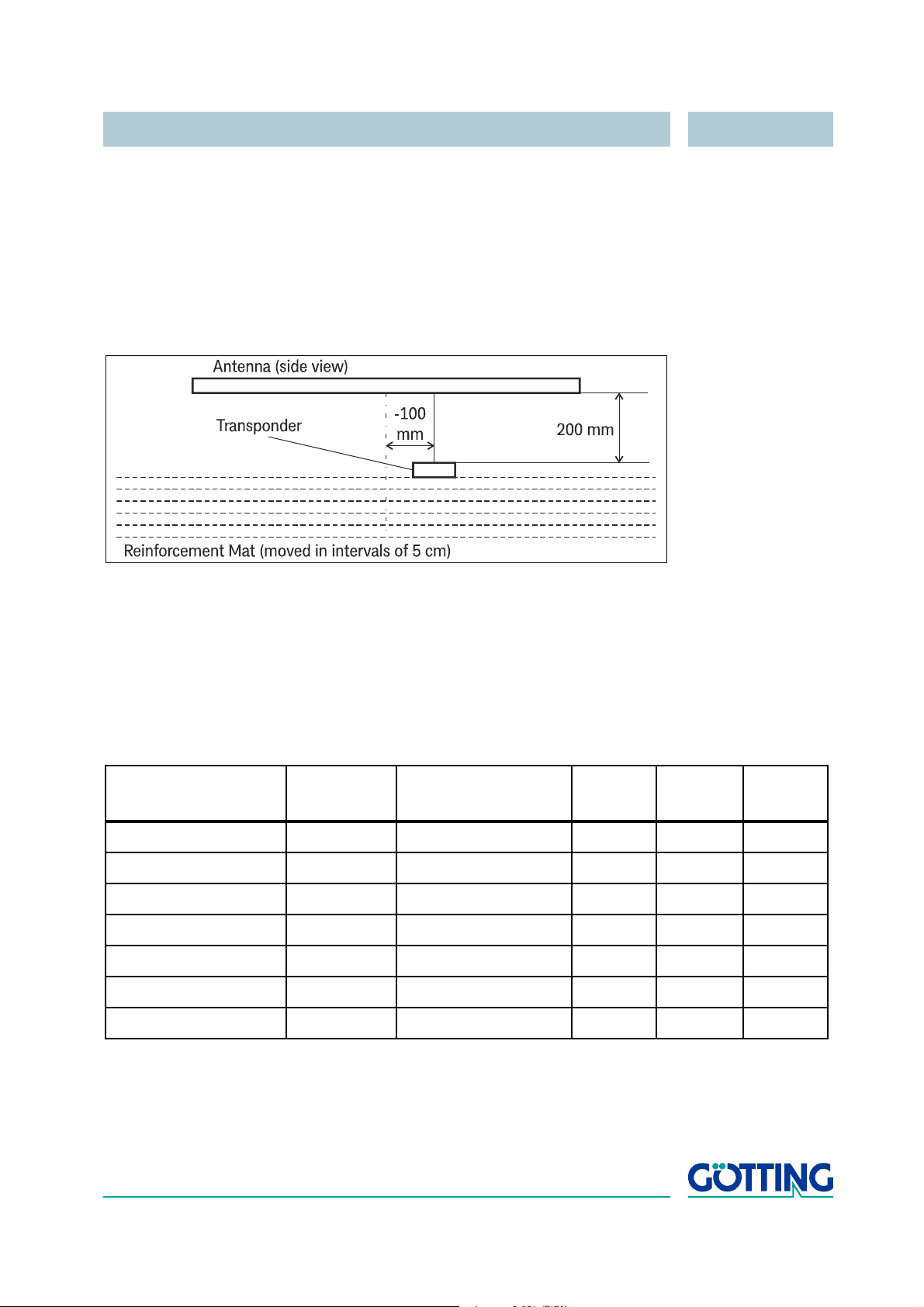
Appendix HG 98860ZA
Measurements have been carried out with a steel frame above the antenna in variable
distances. The transponder was positioned at nominal reading distance (250
derneath the antenna. Current consumption was retuned to maximum value, see section 5.3.2.4 on page 38. The measured displacement signal of the transponder is not
influenced through metal as long as the surface of the antenna is covered evenly.
E Influence of reinforcement steel mesh below the transpon-
der
Figure 30 Test setup with Transponder and reinforcement mat
mm) un-
The measurement was performed with a reinforcement mat with the meshes sized at
90 x 240
value of reference coil Us, value of positioning coil Ud and whether the antenna is able
to decode the Transponder code. The position of the transponder was X = -100 mm,
Y = 0 mm.
The transponder was located in a distance of 20 cm below the antenna, and the mat
was lowered in intervals of 5 cm.
Distance between mat
and transponder / cm
mm. The measured parameters were: Tuning value, current consumption,
Tuning value
antenna
Current consumption
antenna / mA
Us / units Ud / units decoding
Without mat 4 980 850 920 yes
25 6 920 750 830 yes
20 6 890 700 780 yes
15 7 860 640 710 yes
10 8 780 460 530 yes
5 9 770 400 460 no
0 12 660 0 0 no
Table 18 Influence of reinforcement steel mesh on the transponder
English, Revision 04, Date: 19.01.2015 53
Page 54
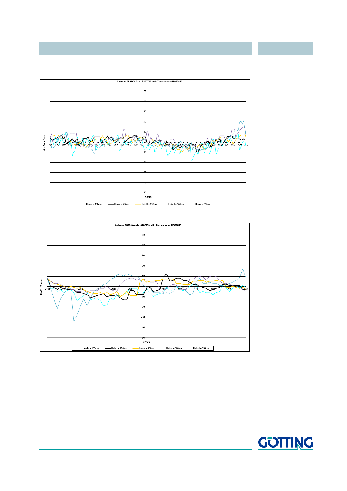
Appendix HG 98860ZA
F Accuracy of the deviation calculation
Figure 31 Typical accuracy of theY-deviation
Figure 32 Typical accuracy of the X-deviation
English, Revision 04, Date: 19.01.2015 54
Page 55

List of Figures HG 98860ZA
10 List of Figures
Figure 1 Examples of automated vehicles using transponder systems............ 5
Figure 2 System components (optional extras in brackets) .............................. 6
Figure 3 Track guiding a vehicle with one antenna........................................... 7
Figure 4 Polarity of the deviation ....................................................................... 7
Figure 5 Antenna dimensions............................................................................ 8
Figure 6 Application of the washers while mounting the antenna..................... 8
Figure 7 Diagram: Commissioning Protocol / insignificant interference level;
shown is the sum voltage over the travelled distance....................... 11
Figure 8 Diagram: Commissioning Protocol / undisturbed Transponder deco-
ding.................................................................................................... 11
Figure 9 Diagram: Commissioning Protocol / high interference level; shown is
the sum voltage over the traveled distance ...................................... 12
Figure 10 Diagram: Commissioning Protocol / jammed decoding (function still
ensured)............................................................................................. 13
Figure 11 Diagram: Commissioning Protocol / false POSI Pulse generated
through noise and threshold set too low ...........................................13
Figure 12 Photo Transmitter-Receiver Antenna HG 98860ZA........................... 15
Figure 13 Drawing Antenna HG 98860ZA (with casing dimensions)................ 16
Figure 14 16-pin Antenna connection socket.................................................... 17
Figure 15 Formula: Minimum update rate.......................................................... 18
Figure 16 CAN Bus Infrastructure (Example) .................................................... 25
Figure 17 Main menu of the monitor program ................................................... 33
Figure 18 Menu: (S)erial Output......................................................................... 35
Figure 19 Menu: „(D)isplay Telegram Content“ ................................................. 36
Figure 20 Menu: (T)ime & Code ........................................................................ 37
Figure 21 Menu: (F)requency & Antenna Tuning .............................................. 38
Figure 22 Formula: Calculation of the receiver frequency................................. 38
Figure 23 Menu: C(A)N-Parameters .................................................................. 39
Figure 24 Menu: display (X)Histogram .............................................................. 41
Figure 25 Menu: display (Y)Histogram .............................................................. 42
Figure 26 Update program: Operating Elements .............................................. 45
Figure 27 Update program: programming procedure ...................................... 45
Figure 28 Diagram procedure 3964R; antenna —> SPS .................................... 50
Figure 29 Diagram procedure 3964R; SPS —> antenna .................................... 51
Figure 30 Test setup with Transponder and reinforcement mat........................ 53
Figure 31 Typical accuracy of theY-deviation ................................................... 54
Figure 32 Typical accuracy of the X-deviation .................................................. 54
English, Revision 04, Date: 19.01.2015 55
Page 56

List of Tables HG 98860ZA
11 List of Tables
Table 1 Allocation of the 16 pin Antenna Connection Socket ........................ 17
Table 2 Data words in a telegram with 21 byte length ................................... 19
Table 3 Possible system status messages..................................................... 20
Table 4 List of the system commands ............................................................ 22
Table 5 Structure of the CAN Message Object 1........................................... 25
Table 6 Structure of the CAN Message Object 2........................................... 26
Table 7 Structure of the CAN Message Object 3........................................... 26
Table 8 Structure of the CAN Message Object 4........................................... 27
Table 9 Coding of commands ........................................................................ 27
Table 10 Connection cable pin allocation........................................................ 28
Table 11 Terminal settings for the monitor program ........................................ 30
Table 12 Description of system variables (monitor program) .......................... 33
Table 13 Trouble shooting................................................................................ 47
Table 14 Technical Data Antenna HG 98860ZA.............................................. 48
Table 15 Technical Data Connection Cable HG 09240DB.............................. 49
Table 16 Influence of metal on the antenna .....................................................52
Table 17 Influence of metal on the antenna .....................................................52
Table 18 Influence of reinforcement steel mesh on the transponder............... 53
English, Revision 04, Date: 19.01.2015 56
Page 57

Index HG 98860ZA
12 Index
Numbers
3964R 50
A
accuracy 54
Analyis Interface 27
Antenna
Dimensions 16
Interfaces 18
Mounting 8
Technical Data 48
C
Company names 59
Connection Cable 28
Technical Data 49
Copyright 59
E
Exclusion of Liability 59
F
Function 6
M
Maintenance 46
Monitor Program 31
Parameter Settings 30
Usage 32
P
Positioning Pulse 27
Procedure „transparent“ 51
Procedure 3964R 50
R
Receiver Frequency
Calculation of the 38
S
Software 30
Software update 44
Softwareupdate 44
System Commands 22
System Components 6
System Monitor 31
System Variables 33
H
HG
09240 6, 28, 49
70653 8, 48
81830 6
98860 5, 6, 8, 17
I
Installation 10
Interfaces
CAN 25
T
Technical Data 48
Telegram 18, 19
Terminal Program 30
trade marks 59
transparent 51
Transponder 8
Trouble Shooting 47
U
Update Rate 18
English, Revision 04, Date: 19.01.2015 57
Page 58
Handbook Conventions HG 98860ZA
13 Handbook Conventions
In documentations of Götting KG the following symbols and assignments are being
used at the time of printing this manual:
Security advices have the following symbols, depending on the emphasis and the
degree of exposure:
NOTE!
ATT ENTION!
CAUTION!
WARNING!
Continuative information and tips are identified as follows:
Tip!
Program texts and variables are highlighted by using the font ’Courier’.
Whenever input of key combinations is required for the operation of programms,
the corresponding
possible to use small and capitalized characters equally).
Sections, figures and tables are automatically numbered consecutively through-
out the entire document. In addition, each document has an index listed behind
the front page, including pages and - whenever the document has more than 10
pages - following the actual system description a figure and table index in the
back. In certain cases (for long and/or complicated documents) a subject index is
added.
Each document provides a table block with metainformation on the front page,
indicating the system designer, author, revision and date of issue. In addition, the
information regarding revision and date of issue are included within the footer of
each page, enabling the exact allocation of the information with a date and cer
tain system revision.
Online-Version (PDF) and printed manual are generated from the same source.
Due to the consistent use of Adobe FrameMaker for the generation of documenta
tion, all directory entries (including page numbers and subject index) and cross
references in the PDF file can be clicked on with the mouse and will lead to the
corresponding linked contents.
eys are ighlighted (in Götting KG programs it is usually
-
-
English, Revision 04, Date: 19.01.2015 58
Page 59

Copyright and Terms of Liability HG 98860ZA
14 Copyright and Terms of Liability
14.1 Copyright
This manual is protected by copyright. All rights reserved. Violations are subject to penal legislation of the Copyright.
14.2 Exclusion of Liability
Any information given is to be understood as system description only, but is not to be
taken as guaranteed features. Any values are reference values. The product charac
teristics are only valid if the systems are used according to the description.
This instruction manual has been drawn up to the best of our knowledge. Installation,
setup and operation of the device will be on the customer’s own risk. Liability for con
sequential defects is excluded. We reserve the right for changes encouraging technical improvements. We also reserve the right to change the contents of this manual
without having to give notice to any third party.
14.3 Trade Marks and Company Names
-
-
Unless stated otherwise, the herein mentioned logos and product names are legally
protected trade marks of Götting
be trade marks or registered trade marks of the corresponding companies.
KG. All third party product or company names may
English, Revision 04, Date: 19.01.2015 59
 Loading...