

Page 1
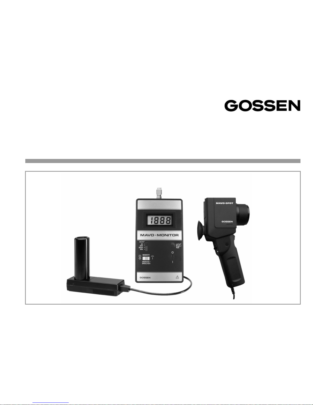
MAVO-MONITOR / MAVO-SPOT
Instrument Set for Contact or Distant Measurements of Luminances
15043
1/1.00
Operating Instructions
Page 2
2 GOSSEN Foto- und Lichtmeßtechnik
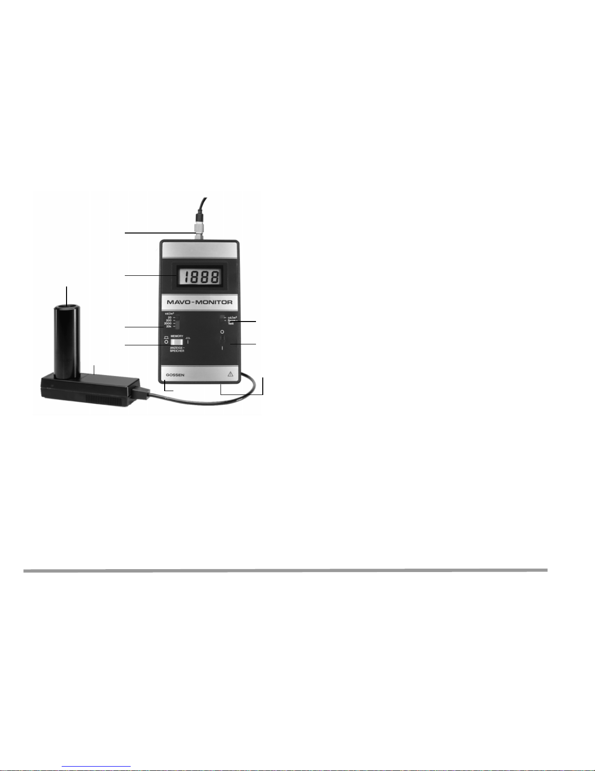
1 Display
2 Slider switch cd/m² – segment test
3 ON/OFF switch
4 Rechargeable battery socket
5 Socket for recorder output
6 Hold key
7 Selector slider switch
8 Socket for connection to meas. sensor
9 Measuring sensor
10 Sensor aperture
Contents Page
1 Description of MAVO-MONITOR .............3
2 Applications .............................................. 3
3 Operating the MAVO-MONITOR ..............4
3.1 Inserting the Battery ........................................4
3.2 Preparing the Measur e m en t .......... ... ... ............4
3.3 Contact Measurements ...................................5
3.4 Overflow ..........................................................5
4 Functioning and Circuitry ....... ........... ......6
5 What is Luminance? ................................6
6 Technical Data ......................... .................7
7 Maintenance ..............................................8
7.1 Calibration Service ..........................................8
7.2 Cleaning and Maintenance .............. ................8
8 Description of MAVO-SPOT ......... ............9
9 Operating the MAVO-SPOT ...................10
9.1 Inserting the Battery ......................................10
9.2 Battery Control ... ... .............. ... .............. .. ... .....11
9.3 Preparing the Measur e m en t .......... ... ... .......... 11
9.4 Measuring ................ ................ ................. .....11
10 Technical Data ................... ........... ..........12
11 Maintenance ............................................13
11.1 Calibration Service ........................................13
11.2 Cleaning and Mai ntenance ............. ...............13
1
7
6
8
2
3
5
9
10
4
Page 3

GOSSEN Foto- und Lichtmeßtechnik 3
1 Description of MAVO-MONITOR
The MAVO-MONITOR is an illumination level
meter designed for easy and precise measure-
ments in cd/m² on backlighted or luminous surfaces. The instrument is colour-corrected, i.e. the
spectral response of the photo diode is adapted to
that of the human eye V (λ).
The correction filters are incorporated in the sensor. They can thus measure all salient kinds of
light without having to take correction factors into
account.
The recorder output of the MAVO-MONITOR
makes it particularly suitable for monitoring applications, checking technical acceptance conditions
and wherever hardcopy results are required.
2 Applications
Contact Measurements
with the MAVO-MONITOR
placed directly on the surface to be measured.
Suitable for
• monitors
• television screens
• light boxes
• light displays
Measuring at a Distance
Using the MAVO-MONITOR plus
MA VO-SPOT attachment.
Suitable for measuring
• monitors taking the existing ambient light
into consideration
• lighting of streets and airfield areas
• lighting of sports areas
• ligh t contrasts at work stations
• lighting in museums
• uniform illumination of projection screens
Page 4
4 GOSSEN Foto- und Lichtmeßtechnik
3 Operating the MAV O-MONIT O R
3.1 Inserting the Battery
The battery compartment is to be found at the
back of the unit.
To open the compartment turn the screw through
90° using a coin so that the lid pops open.
Insert the included battery into the battery compartment.
Make sure you insert the batteries with the right
polarity. Close the battery compartment.
Attention
Only use new batteries or rechargeable accus
according to IEC 6 LF 22!
3.2 Preparing the Measurement
Connect the measuring sensor to the
MAVO-MONITOR. Switch the instrument on using
the ON/OFF switch and carry out a segment test.
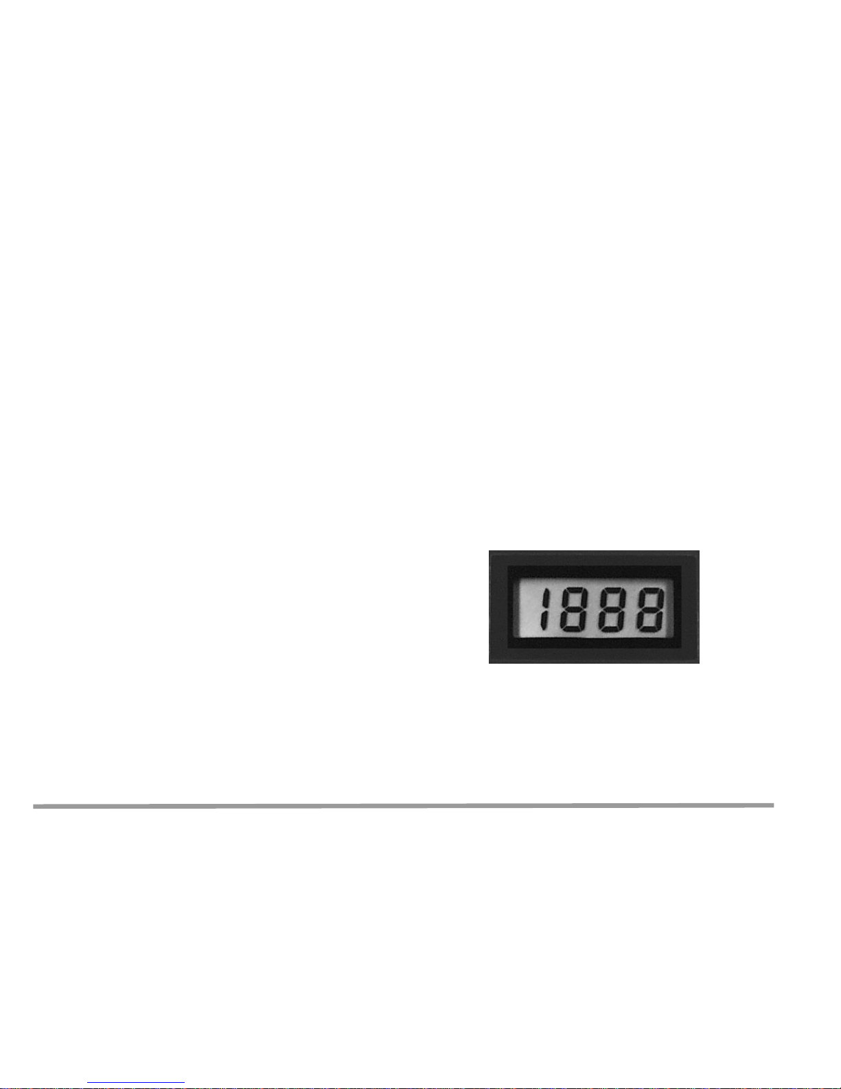
Segment test
Move the slider switch to the position
“Segm.-Test”. The display is working properly
when the readout 1888 appears for 1.5 seconds
(followed by an undefined readout).
If not, the instrument must be returned to our
Service Department.
Page 5
GOSSEN Foto- und Lichtmeßtechnik 5
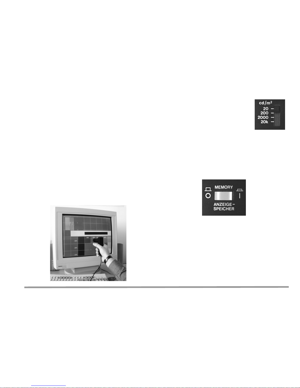
3.3 Contact Measurements
Move the slider switch to “cd/m²”.
Place the sensor flat on the surface to be measured. Select the desired measuring range using
the selector slider switch.
Notes
– Strong ambient light can influence the measure-
ment. This is particularly important when a glass
pane is sandwiched between the actual screen
surface and the sensor.
– Artificial light sources do not achieve full lumi-
nance until they have warmed up. It is therefore
advisable to switch on 15 min. earlier.
– The luminance of light sources depends on the
power supply i.e. check the voltage with a voltmeter where necessary.
3.4 Overflow
If the measuring range is exceeded
the display merely shows a 1 on
the left, the other digits will be
blank. Move to the next higher
range.
Display Hold
Pressing the display hold button will “freeze” the
readout at that time. Pressing this button again will
release the hold and normal measurements can
be resumed.
Page 6

6 GOSSEN Foto- und Lichtmeßtechnik
4 Functioning and Circuitry
The instrument essentially comprises the sensor
containing the silicon photocell and the correction
filters and the instrument itself. In an integrated
(IC) operational amplifier the short-circuit current
of the photocell, which is located directly at the
input to the op amp, is measured. This kind of
short-circuit current measurement has the advantage of low dependency on temperature and producing a linear result. Range selection is done by
means of the selector slider switch. Sensors can
be interchanged by means of the “sensor matching” circuit in conjunction with the potentiometer
control in the sensor. This circuit also generates
the voltage level for the recorder output.
5 What is Luminance?
This is the amount of light as registered by the
eye. Luminance thus expresses the brightness of
a surface. The luminance in a certain direction is
the density of the illumination emitted from the
light-source surface, i.e. the quotient of the illuminance J in the direction concerned and the illuminating surface area A • cos ε.
The unit of measurement of luminance is the candela per square centimeter = cd/cm²
or for very low luminance levels cd/m² (the former
unit was: “Apostilb” (1 asb = 0.31831 cd/m²)).
Also used:
1 fL (footlambert) = 3.426 cd/m²
1 cd/ft² (candela per square foot) = 10.76 cd/m²
A • cos ε
A
ε
Probe
(7)
IC
cd/m²
Segment test
Probe
Adaptor
Power Supply
Battery Monitoring
Segment test
Analogue
Digital
Converter
ON
Batt.
Recorder Output Store
D
I
S
P
L
A
Y
Page 7

GOSSEN Foto- und Lichtmeßtechnik 7
6 Technical Data
Meas. Ranges /
Resolution 0.01...19.99 cd/m² ( 10 mcd/m²)
0.1...199.9 cd/m² (100 mcd/m²)
1...1999 cd/m² ( 1 cd/m²)
0.01...19.99 kcd/m²( 10 cd/m²)
Accuracy for incandescent bulb light
(normal light A)
± (2.5% of rdg. + 4 digits)
Additional error for other light
sources (acc. to CIE TC - 2.2):
max. ± 3% of rdg.
Recorder
Output 0 ... 1.00 V for each range.
Necessary input impedance
of recorder at least ≥ 500 kΩ.
The recorder output socket
complies with safety class III
requirements.
Meas. Sensor
– Aperture
– Meas. Area
18.5 mm ∅
10 x 10 mm
Display LCD 3½ digits
Digit Height 12.7 mm
Power Supply 9 V IEC 6 F 22 battery
(e.g. Mallory MN 1604/Alkali
or Varta Super 438)
Accu IEC 6 LF 22
(e.g. Varta 4002)
Case Plastic
Cable Length 1.5 m
Dimensions
– Meas.
Instrument 86 x 153 x 25 mm
– Meas. Sensor 32 x 105 x 95 mm
– Ever-Ready
Case approx. 140 x 200 x 40 mm
Weight approx. 350 g without b atteries
Included
Accessories Ever-ready case
Optional Accessories
MAVO-SPOT attachment
for measuring at a distance
Page 8

8 GOSSEN Foto- und Lichtmeßtechnik
7 Maintenance
7.1 Calibration Service
The instruments are calibrated at the light of
a scientific standard lamp having a colour
temperature of 2856 K, fully in accordance with
the PTB standard.
Depending on how the instrument is being used
we recommend a recalibration interval between
12 and 18 months.
For this purpose please contact our
Calibration Service Department
(telephone +49 911 8602 172).
7.2 Cleaning and Maintenance
Keep the instrument dry and clean, away from
dust. Avoid exposing the sensor to unnecessary
light.
Please use a slightly damp cloth only for cleaning
the plastic surfaces; avoid the use of cleaning
agents or other strong chemicals. The lenses
should be cleaned with a special cloth or brushes
as used for optics.
Page 9

GOSSEN Foto- und Lichtmeßtechnik 9
1 ON/OFF switch
2 B atte ry control
3 Lens with protective filter or close-up lenses
4 Ocular with eye-cup
5 Battery compartment
6 Con nection cable
8 Description of MAVO-SPOT
The MAVO-SPOT is a very precise measuring
instrument attached to the basic instrument
MAVO-MONITOR with a measuring angle of 1°.
This combined equipment set permits measuring
the luminance at distances from 1 m to ∞ while
including the existing ambient light.
That distance can be further reduced down to
34 cm when using the close-up lenses which are
available as optional accessories.
The MAVO-SPOT is colour-corrected, i.e. the
spectral response of the photo diode is adapted to
that of the human eye V (λ) according to
DIN 5032/T7 class B.
Measuring at a Distance
Using the MAVO-MONITOR plus
MA VO-SPOT attachment.
Suitable for measuring
• monitors taking the existing ambient light
into consideration
• lighting of streets and airfield areas
• lighting of sports areas
• ligh t contrasts at work stations
• lighting in museums
• uniform illumination of projection screens
3
5
6
2
1
4
Page 10

10 GOSSEN Foto- und Lichtmeßtechnik
9 Operating the MAVO-SPOT
9.1 Inserting the Battery
The battery compartment is located at the front of
the grip of the unit.
Slide the cover of the compartment downwards,
insert the battery and attach the connector clips
to the new battery.
Take care to get the polarity right.
Close the battery compartment.
Attention
Only use new batteries or rechargeable accus
according to IEC 6 LF 22!
Page 11

GOSSEN Foto- und Lichtmeßtechnik 11
9.2 Battery Control
When the instrument is switched on the green LED
on the right of the ON/OFF switch lights up. When
the battery is exhausted the red LED to the left of
the ON/OFF switch will light up. You should then
immediately replace the battery.
A new alkaline-manganese battery will last for
approx. 60 hours of continuous measuring.
9.3 Preparing the Measurement
Screw the protective filter supplied with the instrument or one of the close-up lenses on the ocular of
the MAV O-SPOT. For measuring either the protective filter or one of the close-up lenses must be
attached. Connect the MAVO-SPOT with the
MAVO-MONITOR by means of the connection
cable.
Select a suitable measuring range at the
MA VO-MONITOR and switch both instruments on.
9.4 Measuring
View through the ocular of the SLR viewfinder of
the MAV O-SPOT and direct the measuring circle
you see in the viewfinder to the area to be measured. This area should be illuminated uniformly
and be as large as possible as compared to the
measuring circle.
After that press the memory switch of the MAVOMONITOR and read the measuring value on the
display. When the measuring range is exceeded,
switch over to the next higher range and repeat the
measurement.
Page 12

12 GOSSEN Foto- und Lichtmeßtechnik
10 Technical Data
Light Sensor silicon photodiode
with V(λ) adaptation approx. 4%
acc. to DIN 5032/T7 class B
Meas. Angle 1°
Meas. Range 0.01 cd/m² to 20.000 cd/m²
in 4 ranges
Meas. Accuracy same as MAVO-MONITOR
Power Supply 9 V IEC 6 F 22 battery
(e.g. Mallory MN 1604/Alkali or
Varta Super 438)
Accu IEC 6 LF (e.g. Varta 4002)
Operating
Duration approx. 60 hours
of continuous measuring
EMC Emission
EN 50081-1: 1992
Immission
EN 50082-1: 1992
Cable Length approx.1 m
Dimensions 200 mm x 90 mm x 55 mm
Weight 375g (without battery)
Accessories
Included Protective filter
Ever-ready case
Optional Accessories
– Close-up lens 1: Reducing the meas. distance
down to approx. 51 cm to 1 m
Ordering No.: M496G
– Close-up lens 2: Reducing the meas. distance
down to approx. 34 to 51 cm
Ordering No.: M497G
– Transport case Ordering No.: M495G
Page 13

GOSSEN Foto- und Lichtmeßtechnik 13
Close-up Lenses
The MA VO-SPOT with the included protective filter
attached to the lens permits measuring from a distance of 1 m to ∞.
For shorter distances two different close-up lenses
are available as optional accessories. The closeup lens 1 reduces the measuring distance to
approx. 51 cm to 1 m. Lens no. 2 permits reducing
the measuring distance to approx. 34 to 51 cm.
Please note that one of the close-up lenses or
the protective filter must be mounted to the
lens.
Ever-ready Case and Transport Case
An ever-ready case is included with the MAVOSPOT where also the protective filter and one
close-up lens can be placed.
As an optional accessory a sturdy transport and
storage case for the combined set comprising both
the MAVO-SPOT and the MAVO-MONITOR and
also for two close-up lenses and two spare batteries is available.
11 Maintenance
11.1 Calibration Service
The instruments are calibrated at the light of
a scientific standard lamp having a colour
temperature of 2856 K, fully in accordance with
the PTB standard.
Depending on how the instrument is being used
we recommend a recalibration interval between
12 and 18 months.
For this purpose please contact our
Calibration Service Department
(telephone +49 911 8602 172).
11.2 Cleaning and Maintenance
Keep the instrument dry and clean, away from
dust and with the protective cover placed on the
lens.
Please use a slightly damp cloth only for cleaning
the plastic surfaces; avoid the use of cleaning
agents or other strong chemicals. The lenses
should be cleaned either with a special cloth or
brushes as used for optics.
Page 14

14 GOSSEN Foto- und Lichtmeßtechnik
Page 15

GOSSEN Foto- und Lichtmeßtechnik 15
Page 16

Printed in Germany • Subject to change without notice
GOSSEN Foto- und Lichtmeßtechnik GmbH
Lina-Ammon-Str. 22
90471 Nürnbe rg, Germa ny
Telephone:+49 911 / 8602-181
Telefax: +49 911 / 8602-142
http://www.gossen-photo.de
 Loading...