


 Loading...
Operating Instructions
METRAHIT 27 and METRAHIT H+E CAR
METRA HIT 27M: Digital Multimeter and Milliohmmeter
METRA HIT 27I: Digital Multimeter, Milliohmmeter and Megohmmeter METRA HIT H+E CAR: Mega Tester for Hybrid E-cars
3-349-207-02 15/2.19

|
|
|
|
|
|
|
|
|
|
1 |
|
|
|
|
|
|
|
|
|
|
|
||
|
|
|
|
|
|
|
|
|
|
2 |
|
|
|
|
|
|
|
|
|
|
|||
|
|
|
|
|
|
|
3 |
||||
|
|
|
|
|
|||||||
|
|
|
|
|
|
|
|
4 |
|||
|
|
|
|
|
|
||||||
|
|
|
|
|
|
|
|
|
5 |
||
|
|
|
|
|
|
|
|||||
7 |
|
|
|
|
|
|
|
|
6 |
||
|
|
|
|
|
|
|
|
||||
|
|
|
7 |
||||||||
|
|
|
|||||||||
|
|
|
|
|
|
8 |
|||||
|
|
|
|
|
|||||||
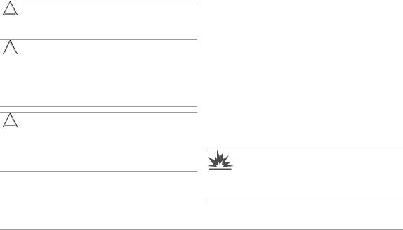
max. 600 V !
1Display (LCD)
2ON|OFF key
Operating mode menu: open submenus / acknowledge entries METRA HIT 27I: background illumination ON / OFF
3DATA|CLEAR key for following functions: save measured value, delete and MIN/MAX
Operating mode menu: Selection of individual menu items
against direction of flow / increase values
4MAN|AUTO key for manual measuring range selection Operating mode menu: Selection of individual menu items
in direction of flow, decrease values
5FUNC key for selecting functions, start key INS measurement Operating mode menu: Exit menu level and return to a higher level/
exit parameters configuration without saving data
6 Rotary selector switch for measuring function
7Connector jacks *
8Connector jacks for mains power battery charger NA HIT 27 (only with storage batteries inserted)
*Earthing input
S- Sense –, for 4-wire connection only with Ω/mΩ/mΩ@1A S+ Sense +, for 4-wire connection only with Ω/mΩ/mΩ@1A V; Ω; °C, MΩ measurement input
3 |
4 |
5 |
|
6 |
|
|
|
|
|||||||||
10 |
|
|
|
|
|
|
|
|
|
|
|
|
|
|
|
|
|
|
|
|
|
|
|
|
|
|
|
|
|
|
|
|
|
|
|
|
|
|
|
|
|
|
|
|
|
|
|
|
|
|
|
|
|
|
|
|
|
|
|
|
|
|
|
|
|
|
|
|
|
||
9 |
|
|
|
|
|
|
|
|
|
|
|
8 |
|
|
7 |
||
|
|
|
|
|
|
|
|
|
|
|
|
|
|||||
|
|
|
|
|
|
|
|
|
|
|
|
||||||
1 |
|
|
|
|
|
|
|
|
|
|
|
|
|
|
|||
|
|
|
|
|
|
|
|
|
|
|
|
|
|
|
|
|
|
2 |
|
|
|
|
|
|
|
|
|
|
|
|
|
|
|
|
|
|
|
|
|
|
|
|
|
|
|
|
|
|
|
|
|
|
|
Symbols used in the Digital Display
1Main display with decimal point and polarity display
2Auxiliary display with decimal point and polarity display
3
 : Multimeter in continuous operation,
ON blinks at transmission frequency in transmission mode
4REM: Memory mode operation, disappears after communication
via the interface is ended by means of key or switch operation
5ZERO: Zero balancing
6MAN: Manual measuring range selection
7Unit of measure (if blinking, refer to chapter 11.2 on page 16 and chapter 15 on page 26)
8MIN/MAX: Display of smallest/largest recorded values with time specification
9
 : Acoustic signal enabled,
beeper is activated for corresponding function
10 |
|
|
: |
Low recharcheable battery voltage (< 3.3 V), recharge batteries |
|
|
|
|
|
Standard Equipment
Type |
27M |
27I |
27AS |
27I Set |
H+E CAR |
H+E CAR |
|
|
|
|
|
|
|
Set |
|
Article Number |
M227A |
M227B |
M227C |
M227S |
M227T |
M227U |
|
|
|
|
|
|
|
|
|
Instrument METRA HIT |
27M |
27I |
27I |
27I |
H+ECAR |
H+ECAR |
|
|
|
|
|
|
|
|
|
3 size AA NiMH storage batteries |
• |
• |
• |
• |
• |
• |
|
|
|
|
|
|
|
|
|
Measurement cable set |
KS17-S |
KS17-S |
KS17-S |
KS17-2 |
— |
— |
|
|
|
|
|
|
|
|
|
operating instructions |
• |
• |
• |
• |
• |
• |
|
|
|
|
|
|
|
|
|
abbreviated operating instructions |
• |
• |
• |
• |
• |
• |
|
|
|
|
|
|
|
|
|
GH18 protective rubber |
green |
green |
green |
green |
orange |
orange |
|
cover with carrying strap |
|||||||
|
|
|
|
|
|
||
DAkkS calibration certificate |
• |
• |
• |
• |
• |
• |
|
|
|
|
|
|
|
|
|
Charging unit NA HIT 27 |
— |
• |
• |
• |
• |
• |
|
|
|
|
|
|
|
|
|
Kelvin clips KC4 (1 set = 2 each) |
— |
• |
• |
• |
— |
— |
|
|
|
|
|
|
|
|
|
Kelvin prob. KC27 (1 set=2 each) |
— |
— |
• |
— |
— |
— |
|
|
|
|
|
|
|
|
|
Hard case HC30 |
— |
— |
• |
• |
— |
— |
|
|
|
|
|
|
|
|
|
Hybrid Diagnostic-Kit |
— |
— |
— |
— |
— |
• |
2 |
GMC-I Messtechnik GmbH |

Table of Contents |
|
|
|
|
Page |
1 |
Safety Features and Precautions |
...............................4 |
2 |
Initial Start-Up ............................................................ |
5 |
3Selecting Measuring Functions and Measuring
|
Ranges ....................................................................... |
6 |
3.1 |
Automatic Measuring Range Selection ..................................... |
6 |
3.2 |
Manual Measuring Range Selection ......................................... |
6 |
3.3 |
Quick Measurements .............................................................. |
7 |
4 |
Triple Digital Display .................................................. |
7 |
5 |
Measured Value Storage ............................................ |
8 |
5.1Measured Value Storage – Key Function “DATA”
(Hold/Compare) ...................................................................... |
8 |
6Saving Minimum and Maximum Values
|
“MIN/MAX” with Time Stamp ..................................... |
9 |
7 |
Voltage and Frequency Measurement ...................... |
10 |
7.1 |
Voltage Measurement [V] ...................................................... |
10 |
7.1.1 |
Zero Balancing in the 3 V DC Measuring Range ...................... |
10 |
7.2 |
Frequency Measurement [Hz] ................................................ |
10 |
8 |
Resistance and Diode Measurements ...................... |
11 |
8.1 |
Resistance Measurement (2-wire connection) [Ω] .................. |
11 |
8.1.1 |
Zero Balancing in the 300 Ω and 3 kΩ Measuring Ranges ..... |
11 |
8.2 |
Continuity Test during Resistance Measurement .................... |
12 |
8.3 |
Diode Measurements ........................................................... |
12 |
9 |
Milliohm Measurement (4-Pole-Measurement) ....... |
13 |
9.1 |
Compensation of Cable Resistance ........................................ |
13 |
9.1.1 |
Measurement with Kelvin Probe KC27 ................................... |
13 |
9.2 |
Thermovoltage Compensation ................................................ |
13 |
9.3 |
Milliohm Measurement with 200 mA or 20 mA DC [mΩ] ........ |
14 |
9.4Milliohm Measurement with 1 A Pulsating Measuring Current [mΩ@1 A]
|
(automatic thermovoltage correction in 3 … 300 mΩ range) ........... |
14 |
10 |
Temperature Measurement [°C] .............................. |
14 |
11 |
Insulation Resistance Measurement [MΩ@...V] |
|
|
(METRA HIT 27I and METRA HIT H+E CAR only) ........ |
15 |
11.1 |
Preparing for Measurement ................................................... |
15 |
11.2 |
Insulation Resistance Measurement ....................................... |
16 |
11.3 |
Ending the Measurement and Discharging .............................. |
16 |
|
|
Page |
12 |
Using the Menus – from the Initial InFO Menu to |
|
|
Operating and Measuring Parameters ..................... |
17 |
12.1 |
Sampling rAtE ........................................................... |
17 |
12.2 |
Saving Measured Values ....................................................... |
17 |
12.2.1Memory Mode – DATA Key Function (see also chapter 5.1) ..... |
17 |
|
12.2.2Memory Mode Operation – STORE Menu Function .................. |
18 |
|
12.3 |
Querying Memory Occupancy – INFO MEMO/OCCUP ......... |
18 |
12.4 |
Clearing the Memory – MEMO CLEAr ................................ |
18 |
12.5 |
Activating the Default Values ................................................. |
18 |
12.6 |
Transmission Mode Operation with RS 232 Interface .............. |
19 |
13 |
Characteristic Values ..................................... |
22 |
14 |
Maintenance ............................................................ |
25 |
14.1 |
Storage Batteries and Batteries ............................................. |
25 |
14.2 |
Fuses ................................................................................... |
26 |
14.3 |
Housing ............................................................................... |
26 |
14.4 |
Device Return and Environmentally Compatible Disposal ......... |
26 |
15 |
Multimeter Messages .............................................. |
26 |
16 |
Accessories ............................................................. |
27 |
17Repair and Replacement Parts Service,
Calibration Center* and Rental Instrument Service . 27
18 |
Guarantee ................................................................ |
28 |
19 |
Product Support ....................................................... |
28 |
20 |
Recalibration ............................................................ |
28 |
GMC-I Messtechnik GmbH |
3 |
1Safety Features and Precautions
You have selected an instrument which provides you with high levels of safety.
This instrument fulfills the requirements of the applicable EU guidelines and national regulations. We confirm this with the CE marking. The relevant declaration of conformity can be obtained from GMC-I Messtechnik GmbH.
The METRA HIT27 or METRA HIT H+E CAR respectively is manufactured and tested in accordance with safety regulations IEC 61010–1:2010 / DIN EN 61010–1:2010 / DIN EN 61010–1:2010 / VDE 0411–1:2011. When used for its intended purpose, safety of the operator, as well as that of the instrument, is assured. Their safety is however not guaranteed, if the instrument is used improperly or handled carelessly.
In order to maintain flawless technical safety conditions, and to assure safe use, it is imperative that you read the operating instructions thoroughly and carefully before placing your instrument into service, and that you follow all instructions contained therein.
Observe the following safety precautions:
•The instrument may only be operated by persons who are capable of recognizing contact hazards and taking the appropriate safety precautions. Contact hazards exist anywhere, where voltages of greater than 33 V (RMS) may occur.
•Avoid working alone when taking measurements which involve contact hazards. Be certain that a second person is present.
!Attention!
Maximum allowable voltage between any given connector jack and earth is 600 V, category II.
!Attention!
Nominal system voltage may not exceed 600 V. Voltage measurements may only be performed with the selector switch set to the V 

 or the V~ position. If the multimeter sockets are confused with the sense sockets, the instrument may be damaged and the operator may be subjected to danger!
!Attention! Contact hazard!
Dangerous voltages at the external jacks may be looped through to the sense sockets during voltage measurement. Therefore do not touch the sense sockets.
•Be prepared for the occurrence of unexpected voltages at devices under test (e.g. defective devices). For example, capacitors may be dangerously charged.
•Weak battery
If the „weak battery“ icon appears in the battery level indicator, it’s no longer permissible to perform safetyrelevant measurements. Furthermore, compliance with the listed specifications is no longer assured in the case of a weak battery.
•Make certain that the measurement cables are in flawless condition, e.g. no damage to insulation, no interruptions in cables or plugs etc.
•No measurements may be made with this instrument in electrical circuits with corona discharge (high-voltage).
•Special care is required when measurements are made in HF electrical circuits. Dangerous pulsating voltages may be present.
•Measurements under moist ambient conditions, or with an instrument with condensation moisture are not permitted.
•Be absolutely certain that the measuring ranges are not overloaded beyond their allowable capacities. Limit values are listed in chapter 13 on page 22.
•The device may only be used for measurements of category CAT II 600 V per IEC 61010-1.
CAT II 600 V is applicable for measurements in electrical circuits with a nominal voltage not exceeding 600 V which are directly connected to the low voltage system via mains sockets or similar terminals.
•Maximum allowable interference voltage between the
jacks (7) and earth briefly amounts to 600 VRMS in all selector switch positions in the event of an error. The fuse blows at an interference voltage value of > 3 V in the mΩ range.
•Be prepared for the occurrence of unexpected voltages at devices under test (e.g. defective devices, after testing coil resistance at contactors etc.), for example, capacitors may be dangerously charged. In the interest of safety, always test for the absence of voltage first with the selector switch in the V 

 and V~ positions.
•In order to avoid damage to the instrument when
interference voltages are applied (within allowable limit values), the mΩ measuring circuit is equipped with an F1.6A/1000 V fuse, which makes this measuring circuit highly resistive if excessive current should occur in the event of a fault for the duration of overloading.
•Do not plug the mains power battery charger into the instrument if normal batteries have been installed instead of storage batteries.
Warning!
The instrument may not be operated in explosive atmospheres, or connected to intrinsically safe electrical circuits.
4 |
GMC-I Messtechnik GmbH |

Meanings of symbols on the instrument:
!Warning concerning a source of danger (attention: observe documentation!)
|
|
|
|
|
|
|
Ground |
|
|
|
|
|
|
|
|
|
|
|
|
|
|
||
|
|
|
|
|
|
Mains power battery charger connection for |
|
|
|
+ |
|
|
|
||
|
|
|
|
|
|
|
recharging storage batteries |
|
|
|
|
|
|
|
|
|
|
|
|
|
|
|
|
|
|
|
|
|
|
|
(rechargeable batteries) |
Continuous, doubled or reinforced insulation
CAT II Measurement category II device
Indicates EC conformity
This device may not be disposed with the trash. For further details on the WEEE marking, please refer to our website www.gossenmetrawatt.com and enter search term ’WEEE’.
DAkkS calibration seal (blue seal):
XY123 Consecutive number
D-K- Deutsche Akkreditierungsstelle GmbH – calibration laboratory 15080-01-01 Registration number
2012-08 Date of calibration (year - month)
Repair, Parts Replacement and Balancing
When the instrument is opened, voltage conducting parts may be exposed. The instrument must be disconnected from the measuring circuit before the performance of repairs, the replacement of parts, or balancing. If balancing, maintenance or repair of a live open instrument is required, this may only be carried out by trained personnel who are familiar with the dangers involved.
Defects and Extraordinary Strains
If it may be assumed that the instrument can no longer be operated safely, it must be removed from service and secured against unintentional use.
Safe operation can no longer be relied upon,
•If the instrument or the test probes are damaged
•If the instrument no longer functions
•After long periods of storage under unfavorable conditions (e.g. humidity, dust, or excessive temperature), see „Ambient Conditions“, page 24.
2Initial Start-Up
Storage Batteries or Batteries
Refer to chapter 14.1 regarding correct storage battery or battery installation.
Warning!
The mains power battery charger may not be connected if normal batteries (which are not suited for recharging) have been inserted: Danger of explosion!
!Attention!
As a result of internal voltage monitoring, the instrument may respond as follows if the
battery charge level is low (symbol 
 is displayed):
–Cannot be switched on
–Shuts back down immediately
–Shuts back down immediately when a load is applied during milliohm and insulation resistance measurement.
If this is the case, replace or recharge the storage batteries.
!Attention!
The mains power battery charger may only be used to recharge the storage batteries!
Mains power battery chargers with an output voltage of greater than 5 V may not be used. The milliohmmeter’s internal voltage regulator might otherwise be destroyed. No guarantee claims can be accepted if any mains power battery charger other than the NA HIT 27 is used (available as an accessory).
Switching the Instrument On Manually
Press the ON|OFF key.
As long as the key is held depressed, all of the segments at the LCD are illuminated. The LCD is shown on page 2. Power-up is acknowledged with a brief acoustic signal.
The instrument is ready for use as soon as the key is released.
Switching the Instrument On with a PC
After transmission of a data frame from the PC, the multimeter is switched on. See also chapter 12.6.
Switching the Instrument On Automatically
The multimeter is switched on automatically in the transmission and memory modes.
Note!
Electrical discharge and high frequency interference may cause incorrect displays to appear, and may disable the measuring sequence. In such cases, switch the instrument off and back on again in order to reset. If the problem persists, briefly dislodge the storage batteries from the connector contacts.
GMC-I Messtechnik GmbH |
5 |

Setting Time and Date
See chapter 12 on page 17.
Switching the Instrument Off Manually
Press and hold the ON|OFF key until OFF appears at the display.
Shutdown is acknowledged with two, brief acoustic signals.
Switching the Instrument Off Automatically – SLEEP MODE
The instrument is switched off automatically if none of the keys or the rotary switch are activated for approximately 10 minutes. Shutdown is acknowledged with a brief acoustic signal.
Transmission mode: In this case, checking is first performed to determine whether or not the sampling rate has been set to a value of greater than 10 s. The instrument is switched off after 10 minutes, but the instrument is reactivated 10 s before data is to be saved to memory. The instrument is then switched back off again.
In the transmission mode, the instrument can be manually activated with the ON|OFF key. After activation of this type, the instrument returns to the “SLEEP MODE”.
If the instrument is to be fully shut down, it must first be activated and then switched off with the ON|OFF key. This ends both memory mode and transmission mode operation. We recommend setting the instrument to continuous operation for transmission mode operation.
The continuous operation mode is not effected by automatic shutdown.
Disabling Automatic Shutdown
The instrument can be set to continuous operation.
Press and hold the FUNC key and then switch the instrument on by pressing the ON|OFF key. Continuous operation is indicated at the display with the 


 symbol.
Switching LCD Illumination On and Off (METRA HIT 27I only)
Briefly press the ON|OFF key after the instrument has already been switched on.
Illumination is switched off automatically after approximately 2 minutes.
Note: Electrical discharge and high frequency interference may cause incorrect displays to appear, and may disable the measuring sequence. In such cases, switch the instrument off and back on again in order to reset. If the problem persists, briefly dislodge the storage batteries or batteries from the connector contacts.
Disconnect the instrument from the measuring circuit before opening and refer to chapter 14.1, “Storage Batteries and Batteries”!
3Selecting Measuring Functions and Measuring Ranges
3.1Automatic Measuring Range Selection
The multimeter is equipped with auto-ranging for all measuring ranges, except for temperature measurement, and diode and continuity testing. Auto-ranging is active as soon as the multimeter is switched on. The instrument automatically selects the measuring range which allows for highest possible resolution for the applied quantity. When the instrument is switched to frequency measurement, the previously selected voltage measuring range remains active. The instrument automatically switches to the next highest or next lowest measuring range for the following measured quantities:
|
|
|
Resolu- |
Switching to next |
Switching to next |
|
Measuring Ranges |
highest range |
lowest range |
||||
tion |
||||||
|
|
|
at ±(... d +1 d) |
at ±(... d -1 d) |
||
|
|
|
|
|||
V~, V |
|
, Hz, Ω, mΩ, |
4¾ |
31,000 |
2800 |
|
30 / 300 mΩ at 1 A |
||||||
|
|
|
||||
|
|
|
|
|
|
|
3 mΩ@1A, MΩ@...V |
3¾ |
3100 |
280 |
|||
3.2Manual Measuring Range Selection
Auto-ranging can be deactivated and measuring ranges can be selected manually in accordance with the following table. The manual mode is deactivated by pressing and holding the MAN|AUTO key (approx. 1 s), by activating the rotary switch, or by switching the instrument off and then back on again.
|
|
Acknow- |
|||
|
ledgement |
||||
MAN| |
Function |
||||
Dis- |
|
Acoust. |
|||
AUTO |
|
|
|||
|
|
play |
|
Signal |
|
short |
Manual mode active: |
MAN |
|
1 x |
|
|
utilized measuring range is fixed |
|
|
|
|
|
Range switching sequence for: |
|
|
|
|
|
V: 3 V → 30 V → 300 V → 600 V → 3 V →… |
|
|
|
|
short |
Hz: 300 Hz → 3 kHz → 300 Hz → … |
MAN |
|
1 x |
|
Ω: 30 MΩ → 300 Ω → 3 kΩ → 30 kΩ → 300kΩ → 3 MΩ → … |
|
||||
|
mΩ: 30 mΩ → 300 mΩ → 3 Ω → 30 Ω → 30 mΩ → … |
|
|
|
|
|
mΩ@1A: 3 mΩ →30 mΩ →300 mΩ →3 mΩ → … |
|
|
|
|
long |
Return to automatic range selection |
— |
|
2 x |
|
Automatic range selection is disabled as long as the MIN/MAX function is active.
6 |
GMC-I Messtechnik GmbH |

3.3Quick Measurements
If you wish to perform quicker measurements than those possible with the automatic measuring range selection function, make sure to establish the appropriate measuring range:
•by manual measuring range selection, i. e. by selecting the measuring range with the best resolution, see
chapter 3.2.
or
•via DATA function, see chapter 5. After the first measurement, the proper measuring range will be automatically determined so that measurements are performed more rapidly from the second measured value onwards.
With both functions, the established measuring range is maintained for the subsequent series mode measurments.
4Triple Digital Display
The three digital displays (1 main display and 2 auxiliary displays) show the measured value with decimal and plus or minus sign. The selected unit of measure is displayed as well. A minus sign appears to the left of the value during the measurement of zero-frequency quantities, if the plus pole of the measured quantity is applied to the “ ” input.
“OL” (overload) appears if the measuring range upper limit is exceeded for the following measured quantities:
V AC, V DC, Hz, Ω, |
|
|
|
, mΩ, 30 / 300 mΩ at 1 A: |
30999 |
|
|
|
|||
3 mΩ at 1 A, , MΩ@...V: |
3099 |
||||
The digital display is refreshed at different frequencies for the various measured quantities.
Main Display
Auxiliary Display MIN Auxiliary Display MAX
The main display appears immediately after the multimeter is switched on, but the auxiliary displays have to be activated by pressing the DATA|CLEAR key (except for position MΩ@...V, where the auxiliary displays appear immediately upon selecting the function).
This assures that any undefined existing condition which prevailed when measurement was started is not continuously displayed as a maximum value, e.g. no-load operation.
In the following flowcharts, the initial displays are highlighted through the use of a bold border line.
GMC-I Messtechnik GmbH |
7 |

5Measured Value Storage
The METRA HIT27 provides two entirely different options for storing data:
•Measured Value Memory – DATA Key Function:
Each time a measuring point is contacted, a measured value is stored in accordance with a defined condition (see chapter 5.1).
•Memory Mode Operation – STORE Menu Function:
After activating the STORE menu function, all measured values are saved in accordance with the selected sampling rate. Memory mode operation is ended manually using the same menu function, see
chapter 12.2.
In both cases, saved measured values can be read out with the help of METRAwin10 PC software (as of version 5.22). However, read-out is only possible if a BD232 IR adapter has been plugged into the METRA HIT27 and connected to the PC with an interface cable.
5.1Measured Value Storage – Key Function “DATA” (Hold/Compare)
Measured values can be automatically “frozen” with the DATA hold function. This is useful when, for example, contacting the measuring points with the test probes requires your full attention.
Memory should be cleared before starting a measurement series with the DATA key function.
This assures, on the one hand, that adequate memory capacity is available and, on the other hand, that only data from the last measurement series are read out in a contiguous fashion. Check current memory occupancy to this end:
INFO MEMO/OCCUP
Clear memory if required: MEMO CLEAr.
After the measured value has been applied and the corresponding “condition” from the table below has been fulfilled, the measured value appears at the left-hand auxiliary display and 2 acoustic signals are generated. At the same time, “MAN” appears, indicating that the measuring range is now fixed. The test probes can now be removed from the measuring points, and the measured value can be read from the auxiliary display. If the measured value is less than the
value specified in the table, the instrument is reactivated for storage of the next value and “data” blinks at the display. The
measured value is saved to non-volatile memory, which is acknowledged by an acoustic signal in each case.
Acoustic Signal
MAN
Comparison of measurement values (DATA Compare)
If the newly stored measurement value deviates less than 0.33% of the measuring range from the first measurement value, the acoustic signal (DATA Compare) sounds twice. If it deviates more than 0.33% from the measuring range, only a brief signal sonds.
|
Condition |
Response at Instrument |
Function |
|
Sub-Display |
DATA |
DATA |
Measuring |
Measurement |
Meas. |
|
Acoustic |
|
|
Function |
Value |
DATA |
Signal |
|
|
|
Value |
||||
|
|
|
|
|
|
|
Switch on |
brief |
|
|
|
|
brief |
Store |
|
V, Hz |
> 10% of MR |
is |
is |
brief |
|
displayed |
|||||
(stabilized mea- |
|
|
|
|||
|
Ω, |
0L |
displayed |
2x 2) |
||
surement value) |
|
|
||||
Reactivate 1) |
|
V, Hz |
< 10% of MR |
stored |
|
|
|
Ω, |
0L |
meas. |
blinks |
|
|
|
|
value |
|
|
||
Switch to |
|
|
|
|
|
|
function |
brief |
|
see Table chapter 6 |
|
|
|
MIN/MAX |
|
|
|
|
|
|
Quit |
long |
|
|
is |
is |
2x |
|
|
deleted |
deleted |
|||
|
|
|
|
|
||
1)Reactivation results from falling short of specified measured value limits.
2)When a measurement value is stored for the first time as a reference value, the acoustic signal sounds twice.
For subsequent data hold, two acoustic signals are only generated if the currently frozen value deviates from the fist saved value by less than 0.33% of the measuring range, depending upon resolution.
Key
R = measuring range, MV = measured value
As long as the DATA function is active, the measuring ranges should not be changed manually.
The DATA function is deactivated if the DATA|CLEAR key is pressed and held (approx. 1 s), by turning the rotary switch or by switching the instrument off and back on again.
8 |
GMC-I Messtechnik GmbH |

6Saving Minimum and Maximum Values “MIN/MAX” with Time Stamp
Minimum and maximum values can be displayed at the |
|
|
|||||
auxiliary displays for long-term observation of measured |
|
|
|||||
quantities. |
|
|
|
|
|
|
|
Press the DATA|CLEAR key twice: Current MIN and MAX |
|
|
|||||
values appear at the auxiliary displays. |
|
|
|
|
|||
Automatic range selection is disabled as long as the |
|
|
Current Measured Value |
||||
MIN/MAX function is active. |
|
|
|
|
|||
Press the DATA|CLEAR key once again for a display of the |
|
|
|||||
minimum value and the time of its occurrence. |
|
|
|
||||
Press the DATA|CLEAR key once again for a display of the |
|
|
|||||
maximum value and the time of its occurrence. |
|
|
|
||||
The MIN and MAX values are deleted by pressing and holding |
|
blinks |
|||||
the DATA|CLEAR key (approx. 1 s), by turning the rotary switch, |
|
|
|||||
or by switching the instrument off and back on again. |
|
|
|
||||
|
|
|
|
|
|
|
Current Measured Value |
|
|
MIN and MAX |
Response from Instrument |
|
MAN |
||
|
|
Display |
|
|
|
||
Function |
Measured Values / |
|
Acoustic |
|
|
||
MIN/MAX |
DATA |
Time of |
|
Aux. |
|
|
|
|
|
Measurement |
Main Display |
Signal |
|
|
|
|
|
|
|
Display |
|
|
|
1. |
2 x short |
are |
|
MIN and |
1 x |
MIN |
MAX |
Save |
|
saved |
|
MAX |
|
|
|
|
|
|
|
|
|
||
2. |
short |
|
Current |
t and |
|
|
|
|
measured value |
1 x |
|
Current Measured Value |
|||
Save and |
|
are |
|
MIN |
|
|
|
Display |
short |
saved |
|
t and |
1 x |
|
MAN |
|
|
|
|
MAX |
|
||
3. |
|
are |
|
same as |
|
|
|
Return to 1 |
short |
same as 1 |
1 x |
|
|
||
saved |
1 |
|
|
||||
|
|
|
|
|
|
||
Stop |
long |
are deleted |
is deleted |
is |
2 x |
tMIN |
MIN |
|
|
||||||
|
deleted |
|
|
||||
|
|
|
|
|
|
|
|
|
|
|
|
|
|
|
Current Measured Value |
Note! |
|
|
|
|
|
MAN |
|
No new MIN/MAX values are calculated for a period |
|
|
|||||
of 2 to 4 seconds after the measuring range has been |
|
|
|||||
changed (depending upon measuring function), in |
|
|
|||||
order to allow measured values to settle in. |
|
tMAX |
|
||||
|
|
|
|
|
|
|
MAX |
|
|
|
|
|
|
|
DATA |
|
|
|
|
|
|
|
short |
|
|
|
|
|
|
|
CLEAR |
|
|
|
|
|
|
|
long |
GMC-I Messtechnik GmbH |
|
|
|
|
9 |
||
Loading...