

Page 1
Page 2

Page 3

Page 4

CONTENTS MAVOLOG PRO – Waveform and Transient Recorder
GMC-I Messtechnik GmbH
I
Contents
POWER QUALITY ANALYZER MAVOLOG PRO ..................................................................... 1
WARNINGS, INFORMATION AND NOTES REGARDING DESIGNATION OF PRODUCT ........... 2
BEFORE SWITCHING THE DEVICE ON ................................................................................. 3
DEVICE SWITCH OFF WARNING ......................................................................................... 3
HEALTH AND SAFETY ......................................................................................................... 4
REAL TIME CLOCK .............................................................................................................. 4
DISPOSAL .......................................................................................................................... 5
OPENING OF EQUIPMENT / REPAIR ................................................................................... 5
BASIC DESCRIPTION AND OPERATION ............................................................................... 6
Contents ......................................................................................................................... 6
Description of the MAVOLOG PRO Power Quality Analyzer .......................................... 7
Abbreviation/Glossary .................................................................................................... 8
Purpose and use of the MAVOLOG PRO Power Quality Analyzer ................................ 10
Device application and benefits ................................................................................... 11
Main Features, supported options and functionality of MAVOLOG PRO Power
Quality analyzer ............................................................................................................ 12
CONNECTION 17
Mounting ...................................................................................................................... 18
Electrical connection for MAVOLOG PRO Power Quality Analyzer .............................. 19
Connection of input/output modules .......................................................................... 21
Communication connection ......................................................................................... 24
Connection of Real Time Synchronization module C ................................................... 24
Connection of aux. Power supply ................................................................................. 26
FIRST STEPS 27
Installation wizard ........................................................................................................ 27
Notification icons .......................................................................................................... 29
LCD Navigation ............................................................................................................. 30
SETTINGS 31
MAVO-View software ................................................................................................... 31
Devices management ...................................................................................................... 32
Device settings ................................................................................................................ 34
Real time measurements ................................................................................................ 35
Page 5

MAVOLOG PRO – Waveform and Transient Recorder CONTENTS
II
GMC-I Messtechnik GmbH
Data analysis ................................................................................................................... 37
My Devices ...................................................................................................................... 37
Upgrade .......................................................................................................................... 37
Software upgrading ........................................................................................................ 38
Setting procedure ............................................................................................................ 40
General Settings ........................................................................................................... 41
Description & Location .................................................................................................... 41
Average interval .............................................................................................................. 41
Language ......................................................................................................................... 41
Currency .......................................................................................................................... 41
Temperature unit ............................................................................................................ 41
Date format ..................................................................................................................... 42
Date and time ................................................................................................................. 42
Real Time Synchronization Source .................................................................................. 42
Time zone ........................................................................................................................ 42
Auto Summer/Winter time .............................................................................................. 42
Maximum demand calculation (MD mode) .................................................................... 43
Thermal function ............................................................................................................. 43
Fixed window .................................................................................................................. 43
Sliding windows ............................................................................................................... 44
MD Time constant (min) ................................................................................................. 45
Maximum demand reset mode ....................................................................................... 46
Min/Max reset mode ...................................................................................................... 46
Starting current for PF and PA (mA) ................................................................................ 46
Starting current for all powers (mA) ............................................................................... 46
Starting voltage for SYNC ................................................................................................ 46
Harmonics calculation ..................................................................................................... 46
Reactive power & energy calculation .............................................................................. 46
LCD navigation ................................................................................................................ 47
Connection ................................................................................................................... 48
Connection mode ............................................................................................................ 48
Setting of current and voltage ratios .............................................................................. 48
Neutral line Primary/Secondary current (A) .................................................................... 48
Used voltage/current range (V/A) ................................................................................... 48
Frequency nominal value (Hz) ......................................................................................... 48
Max. demand current for TDD (A) ................................................................................... 48
Wrong connection warning ............................................................................................. 48
Energy flow direction ...................................................................................................... 49
CT connection .................................................................................................................. 49
LCD navigation ................................................................................................................ 49
Communication ............................................................................................................ 50
Push Data Format ........................................................................................................... 50
Push Response Time (sec)................................................................................................ 50
(Push) Time Synchronization ........................................................................................... 50
USB Communication ........................................................................................................ 50
Ethernet communication ................................................................................................. 50
Device Address ................................................................................................................ 51
IP Address ........................................................................................................................ 51
IP Hostname .................................................................................................................... 51
Local port ........................................................................................................................ 51
Subnet Mask .................................................................................................................... 52
Gateway Address ............................................................................................................ 52
NTP Server ....................................................................................................................... 52
Push communication settings ......................................................................................... 52
MAC Address ................................................................................................................... 53
Firmware version ............................................................................................................. 53
Communication modes ................................................................................................... 53
Page 6

CONTENTS MAVOLOG PRO – Waveform and Transient Recorder
GMC-I Messtechnik GmbH
III
LCD navigation ................................................................................................................ 55
Display .......................................................................................................................... 56
Contrast/Black light intensity .......................................................................................... 56
Saving mode (min) .......................................................................................................... 56
Demo cycling period (sec) ............................................................................................... 56
Custom screen 1/2/3 ....................................................................................................... 56
LCD navigation ................................................................................................................ 57
Security ......................................................................................................................... 57
Password - Level 0 >PL0) ................................................................................................. 57
Password - Level 1 >PL1) ................................................................................................. 57
Password - Level 2 >PL2) ................................................................................................. 57
A Backup Password->BP)................................................................................................. 57
Password locks time >min) .............................................................................................. 58
Password setting ............................................................................................................. 58
Password modification .................................................................................................... 58
Password disabling .......................................................................................................... 58
Password and language .................................................................................................. 58
LCD navigation ................................................................................................................ 58
Energy ........................................................................................................................... 59
Active Tariff ..................................................................................................................... 59
Common Energy Counter Resolution............................................................................... 59
Common Energy Cost Exponent ...................................................................................... 59
Counter divider ................................................................................................................ 59
Common Tariff Price Exponent ........................................................................................ 59
1 kWh Price in Tariff (1,2,3,4) .......................................................................................... 60
1 kvarh Price in Tariff (1,2,3,4) ........................................................................................ 60
1 kVAh Price in Tariff (1,2,3,4) ......................................................................................... 60
LED Energy Counter ......................................................................................................... 60
LED Number of pulses ..................................................................................................... 60
LED Pulse Length (ms) ..................................................................................................... 60
Measured Energy ............................................................................................................ 60
Individual counter Resolution .......................................................................................... 60
Tariff Selector .................................................................................................................. 60
Tariff Clock ...................................................................................................................... 61
Holidays/Holiday date 1-20 ............................................................................................. 62
LCD navigation ................................................................................................................ 62
Inputs and outputs ....................................................................................................... 63
Introduction ..................................................................................................................... 63
I/O Modules options ........................................................................................................ 63
I/O Modules..................................................................................................................... 63
Analogue output module ................................................................................................ 63
Analogue input module ................................................................................................... 64
Pulse output module ....................................................................................................... 65
Digital input module ........................................................................................................ 65
Pulse input module .......................................................................................................... 65
Tariff input module.......................................................................................................... 65
Bistable alarm output module......................................................................................... 65
Alarm Output .................................................................................................................. 66
Status (Watchdog) and Relay output module ................................................................. 66
Auxiliary I/O Modules A & B ............................................................................................ 66
RTC Synchronization module C ........................................................................................ 67
LCD navigation ................................................................................................................ 68
Alarms ........................................................................................................................... 69
Alarms PUSH functionality .............................................................................................. 69
Push data to link .............................................................................................................. 69
Pushing period ................................................................................................................. 69
Page 7

MAVOLOG PRO – Waveform and Transient Recorder CONTENTS
IV
GMC-I Messtechnik GmbH
Pushing time delay .......................................................................................................... 70
Alarms group settings ..................................................................................................... 70
Alarm statistics reset ....................................................................................................... 70
MD Time constant (min) ................................................................................................. 70
Compare time delay (sec) ................................................................................................ 70
Hysteresis (%) .................................................................................................................. 70
Response time ................................................................................................................. 71
Individual alarm settings ................................................................................................. 71
Advanced recorders ...................................................................................................... 72
Logical Inputs and Logical Functions ............................................................................... 73
Triggers ........................................................................................................................... 74
Recorders ........................................................................................................................ 93
Conformity of voltage with EN 50160 standard ......................................................... 104
General PQ settings ....................................................................................................... 104
Monitoring mode .......................................................................................................... 104
Electro energetic system ............................................................................................... 104
Monitoring voltage connection ..................................................................................... 105
Nominal supply voltage ................................................................................................. 105
Nominal power frequency ............................................................................................. 105
Flicker calculation function ........................................................................................... 105
Monitoring period (weeks) ............................................................................................ 105
Monitoring start day ..................................................................................................... 105
Flagged events setting .................................................................................................. 105
Sending Reports and Report Details .............................................................................. 106
EN 50160 parameters settings ...................................................................................... 107
Reset ........................................................................................................................... 108
Reset energy counter .................................................................................................... 108
Reset energy counter Cost ............................................................................................. 108
Reset MD values ............................................................................................................ 108
Reset last period MD ..................................................................................................... 108
Synchronize MD ............................................................................................................. 108
Alarm relay [1/2/3/4] Off .............................................................................................. 109
Reset Min/Max values ................................................................................................... 109
Reset alarm statistic ...................................................................................................... 109
LCD navigation .............................................................................................................. 109
MEASUREMENTS 110
Online measurements ................................................................................................ 110
Interactive instrument ................................................................................................ 111
Supported measurements .......................................................................................... 112
Available connections ................................................................................................. 112
Selection of available quantities ................................................................................. 112
Explanation of basic concepts .................................................................................... 117
Sample factor MV .......................................................................................................... 117
Average interval MP ...................................................................................................... 117
Sample frequency .......................................................................................................... 117
Average interval ............................................................................................................ 117
Average interval for measurements and display........................................................... 117
Average interval for min/max values ............................................................................ 117
Average (storage) interval for recorders ....................................................................... 117
Average (aggregation) interval for PQ parameters ...................................................... 117
Power and energy flow ................................................................................................. 118
Calculation and display of measurements ................................................................. 119
Keyboard and LCD display presentation ..................................................................... 119
Measurements menu organization ............................................................................ 120
Page 8

CONTENTS MAVOLOG PRO – Waveform and Transient Recorder
GMC-I Messtechnik GmbH
V
Measurements menu MAVOLOG PRO ....................................................................... 120
Present values ............................................................................................................ 121
Present values on LCD and TFT display ...................................................................... 121
Voltage .......................................................................................................................... 121
Current .......................................................................................................................... 122
Active, reactive and apparent power ............................................................................ 122
Power factor and power angle ...................................................................................... 122
Frequency ...................................................................................................................... 123
Energy counters ............................................................................................................. 123
MD values ..................................................................................................................... 123
Harmonic distortion ...................................................................................................... 123
Harmonic distortion parameters ................................................................................... 124
Flickers evaluation ......................................................................................................... 124
Flickers .......................................................................................................................... 124
Customized screens ....................................................................................................... 124
Min/Max values .......................................................................................................... 125
Average interval for min/max values ............................................................................ 125
Display of min/max values on MAVOLOG PRO ............................................................. 125
Display of min/max values – MAVO-View software...................................................... 126
Alarms ......................................................................................................................... 127
Survey of alarms ......................................................................................................... 128
Demo cycling .............................................................................................................. 129
Harmonic analysis ....................................................................................................... 129
Display of harmonic parameters ................................................................................... 130
Harmonic analasis – MAVO-View ................................................................................. 131
PQ Analysis ................................................................................................................. 134
LCD navigation .............................................................................................................. 142
PQDIF and COMTRADE files on MAVOLOG PRO – concept description ..................... 143
Working with PQDIF and COMTRADE files on the device .......................................... 143
Accessing PQDIF files ..................................................................................................... 143
Accessing COMTRADE files ............................................................................................ 149
PQDiffractor - PQDIF and COMTRADE file viewer ......................................................... 150
TECHNICAL DATA 153
Accuracy ..................................................................................................................... 153
Measurement inputs .................................................................................................. 155
Connection ................................................................................................................. 156
Communication .......................................................................................................... 156
Input/Output modules ............................................................................................... 157
Safety .......................................................................................................................... 160
Time synchronization input ........................................................................................ 160
Universal Power Supply .............................................................................................. 161
Mechanical ................................................................................................................. 161
Ambient conditions .................................................................................................... 161
Real time clock ............................................................................................................ 162
Operating conditions .................................................................................................. 162
Dimensions ................................................................................................................. 163
APPENDICES 165
APPENDIX A: MODBUS communication protocol....................................................... 165
APPENDIX B: DNP3 communication protocol ............................................................. 174
APPENDIX C: Equations............................................................................................... 182
APPENDIX D: XML Data format ................................................................................... 186
Page 9

MAVOLOG PRO – Waveform and Transient Recorder CONTENTS
VI
GMC-I Messtechnik GmbH
APPENDIX E: PQDIF and COMTRADE recorder data storage organization ................. 188
APPENDIX F: IEC61850 protocol support overview .................................................... 191
Page 10

MAVOLOG PRO – Waveform and Transient Recorder
GMC-I Messtechnik GmbH
1
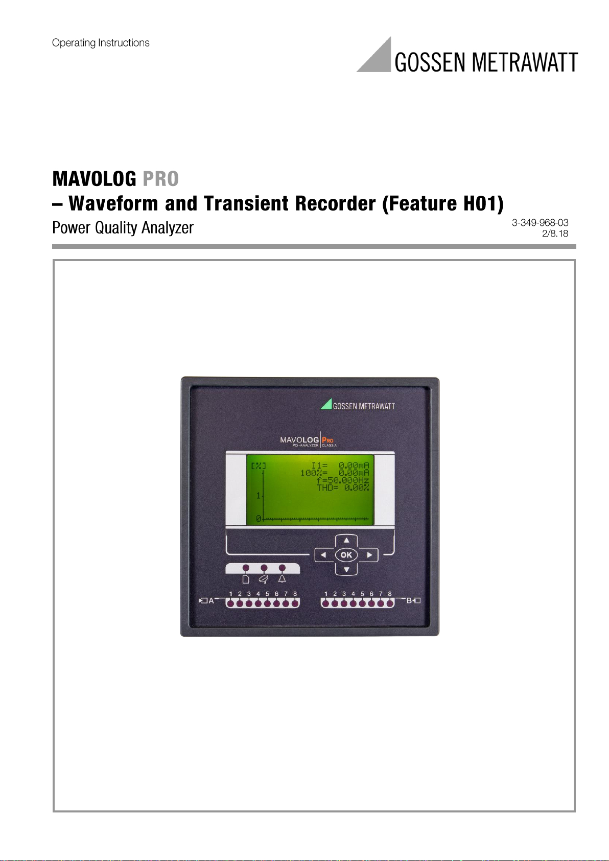
MAVOLOG PRO
- Waveform and Transient Recorder (Feature H01)
MAVOLOG PRO with Feature H01
Page 11
MAVOLOG PRO – Waveform and Transient Recorder
2
GMC-I Messtechnik GmbH
WARNINGS, INFORMATION AND
NOTES REGARDING DESIGNATION
OF PRODUCT
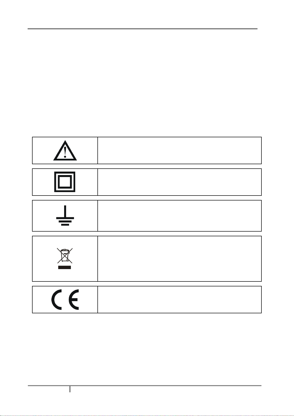
Used symbols:
See product documentation.
Double insulation in compliance with the EN 61010−1 standard.
Functional ground potential.
Note: This symbol is also used for marking a terminal for protective ground
potential if it is used as a part of connection terminal or auxiliary supply
terminals.
Compliance of the product with directive 2012/19/EU, as first priority, the
prevention of waste electrical and electronic equipment (WEEE), and in
addition, the reuse, recycling and other forms of recovery of such wastes so as
to reduce the disposal of waste. It also seeks to improve the environmental
performance of all operators involved in the life cycle of electrical and
electronic equipment.
Compliance of the product with European CE directives.
Page 12

MAVOLOG PRO – Waveform and Transient Recorder
GMC-I Messtechnik GmbH
3
BEFORE SWITCHING THE DEVICE ON
Check the following before switching on the device:
Nominal voltage,
Supply voltage,
Nominal frequency,
Voltage ratio and phase sequence,
Current transformer ratio and terminals integrity,
Protection fuse for voltage inputs (recommended maximal external fuse size is 6 A)
External switch or circuit-breaker must be included in the installation for disconnection of the devices’
aux. power supply. It must be suitably located and properly marked for reliable disconnection of the
device when needed.
Integrity of earth terminal
Proper connection and voltage level of I/O modules
Important: A current transformer secondary should be short circuited before connecting the device.
WARNING!
Feature A01 only (no more available): Auxiliary power supply can be LOW range (19-70VDC, 48-77VAC). Connecting device
with LOW power supply to higher voltage will cause device malfunction. Check devices’ specification before power on!
DEVICE SWITCH OFF WARNING
Auxiliary supply circuits for (external) relays can include capacitors between supply and ground. In order to
prevent electrical shock hazard, the capacitors should be discharged via external terminals after having
completely disconnected auxiliary supply (both poles of any DC supply).
Page 13

MAVOLOG PRO – Waveform and Transient Recorder
4
GMC-I Messtechnik GmbH
HEALTH AND SAFETY
The purpose of this chapter is to provide a user with information on safe installation and handling with the
product in order to assure its correct use and continuous operation.
We expect that everyone using the product will be familiar with the contents of chapter »Security Advices and
Warnings«.
If equipment is used in a manner not specified by the manufacturer, the protection provided by the equipment
may be impaired.
REAL TIME CLOCK
As a backup power supply for Real time clock super-cap is built in. Support time is up to 2 days (after each
power supply down).
Page 14

MAVOLOG PRO – Waveform and Transient Recorder
GMC-I Messtechnik GmbH
5
DISPOSAL
It is strongly recommended that electrical and electronic equipment is not deposit as municipal waste. The
manufacturer or provider shall take waste electrical and electronic equipment free of charge. The complete
procedure after lifetime should comply with the Directive 2012/19/EU about restriction on the use of certain
hazardous substances in electrical and electronic equipment.
OPENING OF EQUIPMENT / REPAIR
The equipment may be opened only by authorized service personnel to ensure the safe and correct operation
of the equipment and to keep the warranty valid.
Even original spare parts may be installed only by authorized service personnel.
In case the equipment was opened by unauthorized personnel, no warranty regarding personal safety,
measurement accuracy, conformity with applicable safety measures or any consequential damage is granted by
the manufacturer.
Page 15

MAVOLOG PRO – Waveform and Transient Recorder
6
GMC-I Messtechnik GmbH
BASIC DESCRIPTION AND
OPERATION
This chapter presents all relevant information about the instrument required to understand its purpose,
applicability and basic features related to its operation.
Apart from this, it also contains navigational tips, description of used symbols and other useful information for
understandable navigation through this manual.
Regarding the options of this instrument, different chapters should be considered since a particular sub variant
might vary in functionality. More detailed description of device functions is given in chapters Main Features,
Supported options and Functionality.
The MAVOLOG PRO Advanced Power Quality Analyzer is available in 144 mmx144 mm panel mounting
enclosure. Specifications of housing and panel cut out for housing is specified in chapter
Contents
Contents and size of a packaging box can slightly vary depending on type of consignment.
Single device shipment or a very small quantity of devices is shipped in a larger cardboard box, which offers
better physical protection during transport. This type of packaging contains the following items:
Measuring instrument
Fixation screws
Pluggable terminals for connection of inputs, aux. Power supply and I/O modules
Short installation manual
When larger quantities of devices are sent they are shipped in smaller cardboard boxes for saving space and
thus reducing shipment costs. This type of packaging contains:
Measuring instrument
Fixation screws
Pluggable terminals for connection of inputs, aux. power supply and I/O modules
Short installation manual
All related documentation on this product can be found at www.gossenmetrawatt.com. The instrument
desktop based setting software – MAVO-View, together with accompanying drivers can be found on our web
page www.gossenmetrawatt.com. Due to environmental reasons, all this information is longer provided on a
separate CD.
CAUTION
Please examine the equipment carefully for potential damage which might have occurred during transport!
Page 16

MAVOLOG PRO – Waveform and Transient Recorder
GMC-I Messtechnik GmbH
7
Description of the MAVOLOG PRO Power Quality Analyzer
The MAVOLOG PRO Advanced Power Quality Analyzer is a comprehensive device intended for permanent
monitoring of power quality from its production, transmission, distribution all the way to the final consumers,
who are most affected by inadequate voltage quality. It is mostly applicable in medium and low voltage
applications.
Lack of information regarding supplied voltage quality can lead to unexplained production problems and
malfunction or can even damage equipment being used during factory production process. Therefore, this
device can be used for the needs of electrical utilities (evaluation against standards) as well as for industrial
purposes (e.g. for monitoring the level of supplied power quality).
Page 17
MAVOLOG PRO – Waveform and Transient Recorder
8
GMC-I Messtechnik GmbH
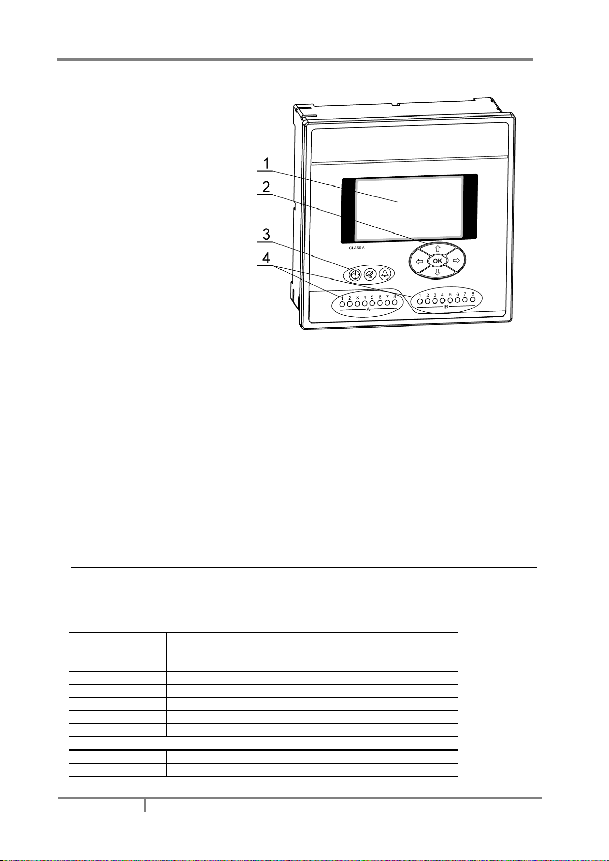
Appearance
1 – Graphical LCD
2 – Navigation keyboard
3 – General operation LED indicators
(clock synchro./comm./alarm)
4 – I/O status LED indicators
Graphical LCD:
A graphical LCD with back-light is used for displaying measuring quantities and for a display of selected
functions when setting the device.
Navigation keyboard:
The "OK" key is used for confirming the settings, selecting and exiting the display. Direction keys are
used for shifting between screens and menus.
LED indicators:
There are two types of LED indicators positioned on the front panel. General operation LED indicators
and I/O status LED indicators.
General operation LED indicators warn on certain device status. The left-most (red) indicator indicates
that the device internal clock is synchronized (via GPS, IRIG-B or NTP protocol). The middle (green) one
is blinking when transmitting MC data via communication to the server. The right-most (red) one is
blinking when any of the alarm conditions is fulfilled.
I/O state LED indicators are in operation when additional Modules A and/or B are built-in. These
modules can have the functionality of Digital input or Relay output. They are indicating the state of a
single I/O. Red LED is lit in either of the following conditions:
Relay output is activated
Signal is present on Digital input
Abbreviation/Glossary
Abbreviations are explained within the text where they appear the first time. Most common abbreviations and
expressions are explained in the following table:
Term
Explanation
RMS
Root Mean Square value
Flash
Type of a memory module that keeps its content in case of power
supply failure
Ethernet
IEEE 802.3 data layer protocol
MODBUS / DNP3
Industrial protocol for data transmission
Memory card
Multimedia memory card. Type MMC and SD supported.
MAVO-View
Setting Software for GOSSEN METRAWATT
PA total
Power Angle calculated from total active and apparent power
Term
Explanation
PA
phase
Angle between fundamental phase voltage and phase current
PF
phase
Power factor, calculated from apparent and active power (affected
Page 18

MAVOLOG PRO – Waveform and Transient Recorder
GMC-I Messtechnik GmbH
9
by harmonics)
THD (U, I)
Total harmonic distortion
TDD (I)
Total demand distortion (according to IEEE Std. 519-1992). Indicates
harmonic distortion at full load.
K factor (I)
Indicates a weighting of the harmonic load currents according to
their effects on transformer heating. (according to IEEE C57.110)
CREST factor (I)
Indicates a ratio between the peak amplitude of the waveform and
the RMS value of the waveform.
MD
Max. Demand; Measurement of average values in time interval
FFT graphs
Graphical display of presence of harmonics
Harmonic voltage −
harmonic
Sine voltage with frequency equal to integer multiple of basic
frequency
InterHarmonic
voltage −
interharmonics
Sine voltage with frequency NOT equal to integer multiple of basic
frequency
Flicker
Voltage fluctuation causes changes of luminous intensity of lamps,
which causes the so-called flicker
RTC
Real Time Clock
Sample factor
Defines a number of periods for measuring calculation on the basis of
measured frequency
Mp − Average interval
Defines frequency of refreshing displayed measurements
Hysteresis [%]
Percentage specifies increase or decrease of a measurement from a
certain limit after exceeding it.
IRIG-B
Serial Inter-range instrumentation group time code
GPS
Satellite navigation and time synchronization system
PO
Pulse output module
TI
Tariff input module
RO
Relay output module
BO
Bistable alarm output module
AO
Analogue output module
DI
Digital input module
PI
Pulse input module
AI
Analogue input module
WO
Status (watchdog) module – for supervision of proper operation
PQDIF
Power Quality Data Interchange Format, which is a binary file format
(according to IEEE Std 1159.3-2003) that is used to exchange power
quality data among different SW products.
COMTRADE
Common format for Transient Data Exchange for power systems is a
file format for storing oscillography and status data related to
transient power system disturbances.
Waveform
Represents the detailed time-dependent shape and form of a
voltage, current or logical input signal
Transient
Represents power quality disturbances that involve destructive high
magnitudes of current and voltage or even both. They exist in a very
short duration from less than 50 nanoseconds to as long as 50
milliseconds.
Disturbance
These are used for monitoring long-term disturbances. Every half/full
cycle, RMS value is calculated, based on the previous cycle.
PQ
Power Quality
List of common abbreviations and expressions
Page 19

MAVOLOG PRO – Waveform and Transient Recorder
10
GMC-I Messtechnik GmbH
Purpose and use of the MAVOLOG PRO Power Quality
Analyzer
This instrument performs measurements in compliance with regulatory requested standard EN 61000-4-30 and
evaluates recorded parameters for analysis according to parameters defined in European power quality
standard EN50160. It enables storage of a wide variety of highly detailed oscillography data in 8GB of internal
flash memory based on a sophisticated trigger settings mechanism. Data can be stored in standardized PQDIF
(IEEE 1159-3) and COMTRADE (IEEE C37.111) file formats which can easily be exchanged with third party PQ
analysis SW systems.
Moreover the MAVOLOG PRO stores measurements and quality reports in internal memory for further
analysis. By accessing recorded or real time values from multiple instruments installed on different locations it
is possible to gain the overall picture of the complete systems’ behavior. This can be achieved with regard to
MAVOLOG PRO accurate internal real time clock and wide range of synchronization sources support, which
assure accurate, time-stamped measurements from dislocated units.
Stored data can then be transferred to a PC or server for post analysis. The simplest way this is done is by
directly connecting a PC with installed MAVO-View Setting Studio SW via USB cable. In cases where multiple
devices are used the MAVO-Database system server usage is recommended where all relevant data from all
system connected instruments is always available from a centralized database through the push XML
communication mechanism. To save server space high precision data can also be transferred from a selected
device on-demand using FTP.
The following characteristics are measured and recorded:
Monitored Power Quality indices as defined by EN 50160
Phenomena
PQ Parameters
Frequency variations
Frequency distortion
Voltage variations
Voltage fluctuation
Voltage unbalance
Voltage changes
Rapid voltage changes
Flicker
Voltage events
Voltage dips
Voltage interruptions
Voltage swells
Harmonics & THD
THD
Harmonics
Inter-harmonics
Signaling voltage
Page 20

MAVOLOG PRO – Waveform and Transient Recorder
GMC-I Messtechnik GmbH
11
Device application and benefits
The MAVOLOG PRO Quality Analyzer can be used as a standalone PQ monitoring device for detection and
analysis of local PQ deviations, transients, alarms and periodic measurements. For this purpose it is normally
positioned at the point-of-common-coupling (PCC) of industrial and commercial energy consumers to monitor
quality of delivered electric energy or at medium or low voltage feeders to monitor, detect and record possible
disturbances caused by operation of consumers.
Identifying relevant fixed measuring points is the most important task prior to complete system installation.
The implementation of a PQ system itself will not prevent disturbances in network but rather help diagnose
their origins and effects by comparing and scrutinizing data from multiple time synchronized measurement
points.
Therefore the most extensive benefits are achieved when the MAVOLOG PRO is used as a part of a PQ
monitoring system comprising of strategically positioned meters connected to the MAVO-Database software
solution. This three-tier middleware software represents a perfect tool for utility companies, energy suppliers
and other parties on both ends of supply-demand chain. MAVO-Database data collector with “push”
communication system allows automatic recording of all predefined measured parameters in the device. All
sent data are stored in the MAVO-Database, while leaving a copy of the same parameters stored locally in
device memory of each device as a backup copy. Database records can be analyzed, searched as well as viewed
in tabelaric and graphic form using the native MAVO-Database web client application or other third-party
software. (e.g. SCADA systems, OPC server, PQ analysis established software…) At the same time device data
can also be visualized and analyzed on-demand by means of the powerful freely-downloadable MAVO-View
setting studio SW.
Server database records (with a copy in device memory) include numerous parameters of three-phase systems,
which have been setup in the device (PQ parameters, over 700 evaluated electrical quantities, I/O module
related physical parameters (e.g. temp., pressure, wind speed…). On the other hand the database also holds
data on alarms and detailed time-stamped transient, waveform, disturbance PQ data and fast trend trigger
records with complete oscillography data in standardized PQDIF/COMTRADE file formats.
Page 21

MAVOLOG PRO – Waveform and Transient Recorder
12
GMC-I Messtechnik GmbH
Main Features, supported options and functionality of
MAVOLOG PRO Power Quality analyzer
MAVOLOG PRO Advanced Power Quality Analyzer is a perfect tool for monitoring and analyzing medium or low
voltage systems in power distribution and industrial segments. It can be used as a standalone PQ monitoring
device for detection of local PQ deviations. For this purpose it is normally positioned at the point-of-commoncoupling (PCC) of small and medium industrial and commercial energy consumers to monitor quality of
delivered electric energy or at medium or low voltage feeders to monitor, detect and record possible
disturbances caused by (unauthorized) operation of consumers.
User can select different hardware modules that can be implemented in device. Wide range of variants can
cover practically every user’s requirements.
MAVOLOG PRO Advanced Power Quality Analyzer is a compact, user friendly and cost effective device that
offers various features to suit most of the requirements for a demanding power system management:
o Evaluation of the electricity supply quality in compliance with EN50160 with automatic report generation
o Instantaneous evaluation of over 700 electrical measurement quantities values including PQ related
parameters, harmonics (voltage/current THDs, TDDs, up to 63rd current voltage/current harmonics, voltage
phase-phase and inter-harmonics)
o Class A (0.1%) accuracy in compliance with EN61000-4-30
o Oscillography capability for recording waveforms with up to 625 samples/cycle sampling frequency
o Recording of disturbance, trend and Power Quality (PQ) events in trigger related recorders
o All trigger related recorder data available on-demand through FTP and automatically on the MAVO-
Database server via autonomous push communication or on demand
o A sophisticated triggering mechanism to register and record events of various nature:
Transient event generated triggers based on hold-off time (in ms), absolute peak value (%) and fast
change (in %Un/µs)
PQ event generated triggers based on the following events: voltage dip, voltage swell, voltage
interruption, end of voltage interruption, rapid voltage change and inrush current
External Ethernet triggers enabling trigger events with up to 8 different devices within the network
External digital triggers based on logical/digital inputs
Up to 16 combined triggers enabling logical operation on previously configured triggers of various
nature
o Recording a wide variety of data in the internal device 8GB flash memory based on trigger settings:
All activated triggers together with timestamp, duration, condition as well as a reference to an
(optionally) generated transient, waveform, disturbance and fast trend record
Waveform recorder with PQDIF/COMTRADE data format selection, selectable recorded channels
(4×Voltage, 4×Current, 16×Digital input), 19 samp./cycle to 625 samp./cycle resolution, pretrigger
time from 0,01s up to 1s, posttrigger time from 0,01s up to 40s (20s for 625 samp./cycle)
Disturbance recorder with PQDIF/COMTRADE data format selection, selectable recorded channels
(4×P-N Voltage, 3×P-P Voltage, 4×Current, 8×Logical inputs), half/full cycle averaging interval, pretrigger time up to 3000 cycles, post trigger time up to 60000 cycles
Periodic measurements in 4 standard trend recorders A through D each containing up to 32 arbitrarily
evaluated (maximum, minimum, average, maximum demand, minimum demand, actual) quantities
with periods ranging from 1min to 60min
Periodic measurements in advanced fast trend recorders 1 through 4 each containing over 700
arbitrarily evaluated (maximum, minimum, average, actual) quantities with periods ranging from 1s to
60min. The recorder can be set to PQDIF data format selection
32 adjustable alarms in 4 alarm groups each containing up to 8 alarms. Alarms relate to a particular
quantity over/under threshold and serve the purpose of controlling on-device relay outputs as well as
informing the server about the occurrence of alarm events
Recording and on-board evaluation of PQ anomalies and PQ reports based on EN50160
Page 22

MAVOLOG PRO – Waveform and Transient Recorder
GMC-I Messtechnik GmbH
13
o Four quadrant energy measurement in 8 programmable counters with class 0.2S accuracy with up to four
tariffs and an advanced tariff clock. Every Counters’ resolution and range can be defined. The counter
content can be configured as:
Active energy (Wh) import
Active energy (Wh) export
Reactive energy (varh) import
Reactive energy (varh) export
Total absolute active energy (Wh)
Total absolute reactive energy (varh)
Total absolute apparent energy (VAh)
Custom settings (phase dependent, four quadrant – P/Q/import/export selection)
o Automatic range selection of 4 current and 4 voltage channels (max. 12.5 A and 1000 VRMS) with 32 kHz
sampling rate
o Measurements of 40 minimal and maximal values in different time intervals (from 1 to 256 periods)
o Frequency range from 16 Hz to 400 Hz
o Ethernet and USB 2.0 communication support
o Communication - MODBUS, DNP3, FTP, upgradeable to EN 61850 (optionally – see Appendix F)
o Support for GPS, IRIG-B (modulated and digital) and NTP real time clock synchronization
o Up to 20 inputs/outputs (analogue inputs/outputs, digital inputs/outputs, alarm/watchdog outputs, pulse
input/outputs, tariff inputs, bistable outputs)
o MAVO-View Setting studio User-friendly setting and analysis software with FTP communication feasibility
for seamless device settings and single device advanced analysis
o MAVO-Database system SW support for automatic (via autonomous push XML communication) as well as
on demand data transfer (via FTP) from multiple instruments to the server through which relevant recorder
data from each device in the system is available
o On-board Web server support for basic measurement overview
o Multilingual support
o Universal power supply (two voltage ranges)
o 144 mm square panel mounting
o Available with:
128x64 pixel display
o USB memory stick slot (optional)
Page 23

MAVOLOG PRO – Waveform and Transient Recorder
14
GMC-I Messtechnik GmbH
General hardware Features
Default / Optional
General
Class A measuring accuracy (0.1%) according to EN 61000-4-30 Ed.3
●
Voltage auto range up to 1000Vp-p
RMS
●
Current auto range up to 12.5 A
●
4 voltage and 4 current channels with 32 us sampling time
●
Universal power supply type High / Low
● / ○
Two independent communication ports (see data below)
○
Support for GPS / IRIG-B / NTP real time synchronization
● / ● / ●
Up to 20 additional inputs and outputs (see data below)
○
Internal flash memory (8MB+8GB)
●
Real time clock (RTC)
●
standard 144 mm DIN square panel mounting
●
Front panel
Graphical LCD display with back light
●
LED indicator (sync/com./alarm)
●
I/O status LED indicator
●
Control keys on front panel (5 keys)
●
Communication
COM1: Ethernet +USB
●
COM2: Serial (RS232/ RS485 on slot C if other synchronization modes are in use)
●
● − Function is supported (default)
○ − Optional (to be specified with an order)
Page 24

MAVOLOG PRO – Waveform and Transient Recorder
GMC-I Messtechnik GmbH
15
General hardware Features
Default / Optional
Input and output modules
Input / output module 1
2×AO / 2×AI / 2×RO / 2×PO / 2×PI / 2×TI / 1×BO / 2×DI / WO+RO
○/○/○/○/○/○/○/○/○
Input / output module 2
2×AO / 2×AI / 2×RO / 2×PO / 2×PI / 2×TI / 1×BO / 2×DI / WO+RO
○/○/○/○/○/○/○/○/○
Auxiliary input / output module A
I/O A
(1-8) DI / RO
○ / ○
Auxiliary input / output module B
I/O B
(1-8) DI
○
Synchronization module C
I/O C
GPS + 1pps / IRIG-B / COM2
● / ● / ●
●
Function is supported (default)
○
Optional (to be specified with an order)
PO
Pulse output module
TI
Tariff input module
RO
Relay output module
BO
Bistable relay output module
AO
Analogue output module
DI
Digital input module
PI
Pulse input module
AI
Analogue input module – U, I or R (PT100/1000)
WO
Status (watchdog) module – for supervision of proper operation
Page 25

MAVOLOG PRO – Waveform and Transient Recorder
16
GMC-I Messtechnik GmbH
General software Features
Default / Optional
EN 50160 power quality evaluation
●
Automatic PQ report generation
●
Disturbance, trend & PQ event recording
●
Waveform recorder with programmable sampling time
(max 625 samples / period)
●
Standardized PQDIF and COMTRADE format support
●
MAVO-View user friendly setting & analysis software
●
Setup wizard
●
Wrong connection warning
●
Custom screen settings (3 user defined screens on LCD)
●
Demonstration screen cycling
●
Programmable refresh time
●
MODBUS and DNP3 communication protocols
●
Tariff clock
●
MD calculation (TF, FW, SW)
●
Wide frequency measurement range 16 – 400 Hz
●
Programmable alarms (32 alarms)
●
Alarms recording
●
Measurements recording (128 quantities)
●
Measurements graphs (time / FFT)
●
Evaluation of voltage quality in compliance with EN
50160
●
Real time clock synchronization (GPS/IRIG-B/NTP)
●
EN61850 Server
○
● − Function is supported (default)
○ − Optional (to be specified with an order)
Page 26

MAVOLOG PRO – Waveform and Transient Recorder
GMC-I Messtechnik GmbH
17
CONNECTION
This chapter deals with the instructions for measuring instrument connection. Both the use and connection of
the device includes handling with dangerous currents and voltages. Connection shall therefore be performed
ONLY a by a qualified person using an appropriate equipment. GOSSEN METRAWATT d.d. does not take any
responsibility regarding the use and connection. If any doubt occurs regarding connection and use in the
system which device is intended for, please contact a person who is responsible for such installations.
A person qualified for installation and connection of a device should be familiar with all necessary precaution
measures described in this document prior to its connection.
Before use:
Before use please check the following:
Nominal voltage (U
P-Pmax
= 1000 V
ACrms
; U
P-Nmax
= 600 V
ACrms
),
Supply voltage (rated value),
Nominal frequency,
Voltage ratio and phase sequence,
Current transformer ratio and terminals integrity,
Protection fuse for voltage inputs (recommended maximal external fuse size is 6 A)
External switch or circuit-breaker must be included in the installation for disconnection of the devices’ aux. power
supply. It must be suitably located and properly marked for reliable disconnection of the device when needed.
See CAUTION below.
Integrity of earth terminal
Proper connection and voltage level of I/O modules
WARNING!
Wrong or incomplete connection of voltage or other terminals can cause non-operation or damage to the device.
WARNING!
It is imperative that terminal 12 which represents fourth voltage measurement channel is connected to earth pole ONLY.
This terminal should be connected to EARTH potential at all times! This input channel is used only for measuring voltage
between neutral end earth line.
CAUTION
Aux. Supply inrush current can be as high as 20A for short period of time (<1 ms). Please choose an appropriate MCB for
disconnection of aux. supply.
PLEASE NOTE
After connection, settings have to be performed via a keyboard on the front side of the device that reflect connection of
device to voltage network (connection mode, current and voltage transformers ratio …). Settings can also be done via
communication or a memory card (where available).
Page 27
MAVOLOG PRO – Waveform and Transient Recorder
18
GMC-I Messtechnik GmbH
Mounting
MAVOLOG PRO Advanced Power Quality Analyzer is intended only for panel mounting. Pluggable connection
terminals allow easier installation and quick replacement should that be required.
This device is not intended for usage as portable equipment and should be used only as a fixed panel mounted
device.
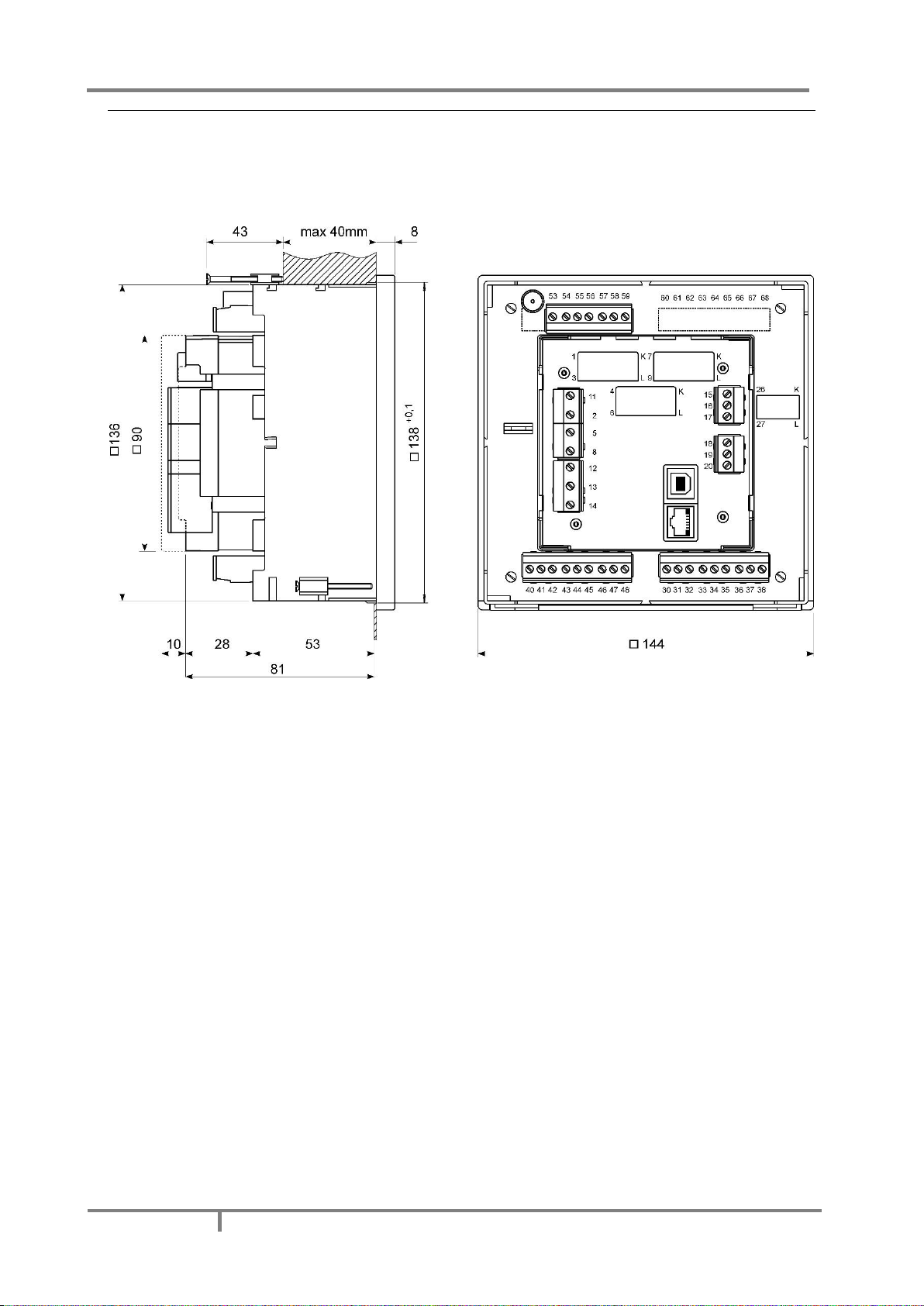
Dimensional drawing and rear connection terminals position
Recommended panel cut out is:
138 x 138 mm + 0.8
Please remove protection foil from the screen.
Page 28
MAVOLOG PRO – Waveform and Transient Recorder
GMC-I Messtechnik GmbH
19
Electrical connection for MAVOLOG PRO Power Quality
Analyzer
Voltage inputs of a device can be connected directly to low-voltage network or via a voltage measuring
transformer to a high-voltage network.
Current inputs of a device are led through a hole in current transformers to allow uninterrupted current
connection. Connection to network is performed via a corresponding current transformer.
Choose corresponding connection from the figures below and connect corresponding voltages and currents.
Information on electrical consumption of current and voltage inputs is given in a chapter
CAUTION
For accurate operation and to avoid measuring signal crosstalk it is important to avoid driving voltage measuring wires close
to current measuring transformers.
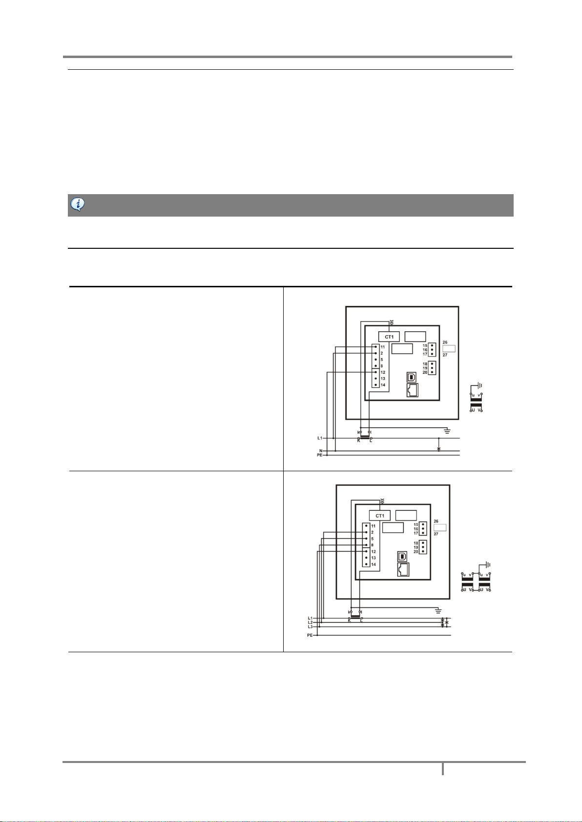
System/ connection Terminal assignment
Connection 1b (1W)
Single-phase connection
Connection 3b (1W3)
Three-phase – three-wire connection
with balanced load
Page 29

MAVOLOG PRO – Waveform and Transient Recorder
20
GMC-I Messtechnik GmbH
Connection 3u (2W3)
Three-phase – three-wire connection
with unbalanced load
Connection 4b (1W4)
Three-phase – four-wire connection
with balanced load
Connection 4u (3W4)
Three-phase – four-wire connection
with unbalanced load
PLEASE NOTE
With all connection schemes must be terminal 12 (PE) ALWAYS connected. Fourth voltage channel is dedicated for
measuring voltage between EARTH (PE, terminal 12) and NEUTRAL (N, terminal 11).
Page 30
MAVOLOG PRO – Waveform and Transient Recorder
GMC-I Messtechnik GmbH
21
Connection of input/output modules
WARNING!
Check the module features that are specified on the label, before connecting module contacts. Wrong connection can cause
damage or destruction of module and/or device.
PLEASE NOTE
Examples of connections are given for device with built in two input/output modules and Ethernet/USB communication.
Connection does not depend on a number of built-in modules and communication, and is shown on the devices’ label.
Connect module contacts as specified on the label. Examples of labels are given below and describe modules
built in the device. Information on electrical properties of modules is given in a chapter Technical Data –
Input/output modules.
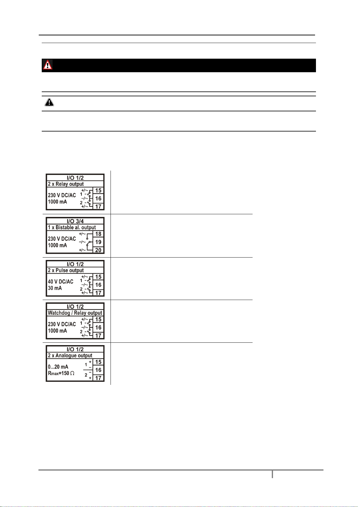
I/O module 1 and 2 (terminal numbers 15-20) – output options
Alarm (relay) output module with two outputs.
Bistable alarm output module; keeps the state
also in case of device power supply failure.
Pulse output (solid state) module with two pulse
outputs for energy counters.
Status (watchdog) output module enables proper
device operation supervision on one output (WD)
and alarm output functionality on the other.
Analogue output module with two analogue
outputs (0…20mA), proportional to measured
quantities.
Page 31

MAVOLOG PRO – Waveform and Transient Recorder
22
GMC-I Messtechnik GmbH
I/O module 1 and 2 (terminal numbers 15-20) – input options
Tariff input module with two tariff inputs for
changeover between up to four tariffs.
Digital input module with two digital inputs
enables reception of impulse signals.
Pulse input module enables reception of pulses
from various counters (water, gas, heat, flow
Analogue input module enables measurements of
DC U, I, R or temp. (PT100, PT1000) values from
external sources. Modules have different
hardware, so programming is possible within one
quantity.
WARNING
In case when only one resistance-temperature analogue input is used, the other must be short-circuited.
Auxiliary I/O module A and B – output options
Digital output relay module with
eight digital outputs enables
alarm functionality.
Auxiliary I/O module A and B – input options
Digital input module with eight
digital inputs enables reception
of digital signals.
Page 32

MAVOLOG PRO – Waveform and Transient Recorder
GMC-I Messtechnik GmbH
23
Synchronization module C
Synchronization module is equipped with support for two different
synchronization methods IRIG-B and GPS modem.
When modulated IRIG-B signal is used it should be connected to BNC
terminal. When level-shift IRIG-B signal is used it should be connected
to 1PPS terminal.
In case of GPS modem, 1pps signal should be connected to 1PPS
terminal and serial RS232 signal should be connected to RS232
terminals.
When IRIG-B (modulated or level-shift) or 1PPS signal is used for time
synchronization serial communication interface (RS232 or RS485) can
be used as a devices’ secondary communication port (COM2).
PLEASE NOTE
Communication port on Module C is primarily dedicated to receive serial coded date and time telegram from a GPS receiver
in order to synchronize internal real time clock (RTC). When other methods are used for synchronizing RTC this
communication port can be used as a secondary general purpose communication port.
Please note that either RS232 or RS485 should be used and not both at a time. Connector terminals that are not used
should remain unconnected otherwise the communication could not work properly.
CAUTION
RTC synchronization is essential part of Class A instrument. If no proper RTC synchronization is provided device operates as
Class S instrument.
CAUTION
Max consumption of +5V supply terminal is 100mA. When GPS with consumption greater the 100mA is used it is advisable
to use external power supply.
Page 33

MAVOLOG PRO – Waveform and Transient Recorder
24
GMC-I Messtechnik GmbH
Communication connection
Primary communication interface (COM1) type is normally specified when placing an order. Device supports
Ethernet communication designed as standard RJ-45 terminal and USB communication designed as standard
USB-B type terminal
Beside primary communication port the device has built in a secondary communication port (COM2) as a part
of a real time synchronization module C. Its operation is described in a chapter referring to a real time
synchronization Serial communication via Synchronization module C (COM2).
Connect a communication line by means of a corresponding terminal. Communication parameters are stated
on the device label, regarding the selected/equipped type of communication. Connector terminals are marked
on the label on a devices’ rear side. More detailed information on communication is given in chapter Settings –
Communications.
Example of a label for Ethernet/USB
communication module equipped
with RJ−45 and USB-B type
connector
Survey of communication connection
Connector
Terminals
Description
Ethernet
RJ−45 100BASE-T CAT5 cable recommended
USB
USB-B
Standard USB 2.0 compatible cable recommended (Type B plug)
Connection of Real Time Synchronization module C
Synchronized real-time clock (RTC) is an essential part of any Class A analyzer for proper chronological
determination of various events. To distinct cause from consequence, to follow a certain event from its origin
to manifestation in other parameters it is very important that each and every event and recorded
measurement on one instrument can be compared with events and measurements on other devices. Even if
instruments are dislocated, which is normally the case in electro distribution network events have to be timecomparable with accuracy better than a single period.
Synchronization module is used to synchronize RTC of the device and to maintain its accuracy for correct
aggregation intervals and time stamps of recorded events appearing in monitored electro distribution network.
Different types of RTC synchronization are possible:
IRIG-B modulated; 1 kHz modulation with <1ms resolution.
IRIG-B unmodulated (level shift)
1PPS + RS232 Date & Time telegram (from GPS)
PLEASE NOTE
For safety purposes it is important that all three wires (Line, Neutral and Protective Earth) are firmly connected. They
should be connected only to the designated terminals as shown on the label above as well as on the front foil.
GPS time synchronization:
1pps and serial RS232 communication with NMEA 0183 sentence support. GPS interface is designed as 5 pole
pluggable terminal (+5V for receiver supply, 1pps input and standard RS232 communication interface).
Proposed GPS receiver is GARMIN GPS18x+
Page 34

MAVOLOG PRO – Waveform and Transient Recorder
GMC-I Messtechnik GmbH
25
IRIG time code B (IRIG-B):
Unmodulated (DC 5V level shift) and modulated (1 kHz) serial coded format with support for 1pps, day of year,
current year and straight seconds of day as described in standard IRIG-200-04. Supported serial time code
formats are IRIG-B007 and IRIG-B127
Interface for modulated IRIG-B is designed as BNC-F terminal with 600 Ohm input impedance. Interface for
unmodulated IRIG-B is designed as pluggable terminal.
Network time protocol (NTP):
Synchronization via Ethernet requires access to a NTP server.
PLEASE NOTE
NTP can usually maintain time to within tens of milliseconds over the public Internet, but the accuracy depends on
infrastructure properties - asymmetry in outgoing and incoming communication delay affects systematic bias. It is
recommended that dedicated network rather than public network is used for synchronization purposes.
CAUTION
RTC synchronization is essential part of Class A instrument. If no proper RTC synchronization is provided device operates as
Class S instrument.
Survey of synchronization connection
Terminals
Connector type
BNC for modulated IRIG-B
and
Pluggable screw terminals for level-shift IRIG-B, GPS modem or
serial RS232 or RS485
Connector
Position
Data direction
Description
BNC connector
600 Ohm input impedance: standard Coaxial cable (55 Ohm) recommended
Screw terminal
53
1PPS (GPS) or
IRIG-B (level shift)
Synchronization pulse
54
To/From (A)
RS485
55
To/From (B)
RS485
56
To
Data reception (Rx)
57
GND
Grounding
58
From
Data transmission (Tx)
59
+5V
AUX voltage +5V
(supply for GPS modem)
When IRIG-B or 1PPS signal is used for time synchronization serial communication interface (RS232 or RS485)
can be used as a devices’ secondary communication port (COM2).
More information regarding use of Synchronization module C please see chapter Inputs and Outputs – RTC
Synchronization module C.
Page 35

MAVOLOG PRO – Waveform and Transient Recorder
26
GMC-I Messtechnik GmbH
Connection of aux. Power supply
Device can be equipped with either of two types of universal (AC/DC) switching power supply.
Feature A00 (Standard): 80...300 V DC
80...276 V AC;
40...65 Hz
Feature A01 (no longer aivailable): 19...70 V DC
48...77 V AC;
40...65 Hz
Power supply voltage depends on ordered voltage. Information on electric consumption is given in chapter
Technical Data – Universal Power Supply. Regarding power supply voltage specification on the label, choose
and connect the power supply voltage:
Feature A00: Connection of universal power supply
type High to terminals 13 and 14.
Feature A01: Connection of universal power supply
type Low to terminals 13 and 14.
WARNING!
Feature A01 only:
Auxiliary power supply can be LOW range (19-70VDC, 48-77VAC). Connecting device with LOW power supply to higher
voltage will cause device malfunction. Check devices’ specification before turn it on!
CAUTION
Aux. supply inrush current can be as high as 20A for short period of time (<1 ms). Please choose an appropriate MCB for
connection of aux. supply.
Page 36

MAVOLOG PRO – Waveform and Transient Recorder
GMC-I Messtechnik GmbH
27
FIRST STEPS
Programming device is very transparent and user friendly. Numerous settings are organized in groups
according to their functionality.
Programming device can be performed using the keypad and display on the front panel. Due to representation
of certain settings not all settings can be programmed this way. All settings can be programmed using MAVOView software.
In this chapter you will find basic programming steps which can be accessed by using keypad and display.
Installation wizard
MAVOLOG PRO
After installation and electrical connection, basic parameters have to be set in order to assure correct
operation. The easiest way to achieve that is use the Installation wizard. When entering the Installation menu,
settings follow one another when the previous one is confirmed. All required parameters shall be entered and
confirmed. Exit from the menu is possible when all required settings are confirmed or with interruption (key
several times) without changes.
Installation wizard menu may vary, depending on built in communication modules. In description below is
marked which menu appears for specific option.
PLEASE NOTE!
All settings that are performed through the Installation wizard can be subsequently changed by means of the Settings menu
or via MAVO-View software.
When entering installation wizard following display is shown:
Installation
Welcome to the
Installation Wizard.
Press OK to continue.
< Main menu
Language
Set device language.
Date
Set device date.
Time
Set device time. If instrument is connected to one of supported time synchronization sources, date and time
are automatically set.
Connection mode
Choose connection from a list of supported connection modes.
Primary voltage
Set primary voltage of monitored system if a device is connected indirectly by means of a voltage transformer.
If device is connected to directly to a low voltage enter this value.
Page 37

MAVOLOG PRO – Waveform and Transient Recorder
28
GMC-I Messtechnik GmbH
Secondary voltage
Set secondary voltage if a voltage transformer is used; set voltage of low voltage network if connection is
direct.
Primary current
Set primary current of monitored system if a device is connected indirectly by means of a current transformer.
Otherwise primary and secondary current should remain the same.
Secondary current
Set secondary current of current transformer or the value of nominal current if connection is direct.
Common energy counter resolution
Define Common energy counter resolution as recommended in table below, where Individual counter
resolution is at default value 10. Values of primary voltage and current determine proper Common energy
counter resolution. For detailed information about setting energy parameters see chapter
Suggested Common energy counter resolutions:
Current
Voltage
1 A
5 A
50 A
100 A
1000 A
110 V
100 mWh
1 Wh
10 Wh
10 Wh
100 Wh
230 V
1 Wh
1 Wh
10 Wh
100 Wh
1 kWh
1000 V
1 Wh
10 Wh
100 Wh
1 kWh
10 kWh
30 kV
100 Wh
100 Wh
1 kWh
10 kWh
10 kWh *
* − Individual counter resolution should be at least 100
Device address
Set MODBUS address for the device. Default address is 33.
IP Address
Set correct IP address of the device. Default setting is 0.0.0.0 and represents DHCP addressing. This setting is
available only when Ethernet communication is built in.
TCP Port
Set TCP communication Port. Default value is 10001. This setting is available only when Ethernet
communication is built in.
Subnet mask
Set network subnet mask. Default value is 255.255.255.0. This setting is available only when Ethernet
communication is built in.
Page 38

MAVOLOG PRO – Waveform and Transient Recorder
GMC-I Messtechnik GmbH
29
Notification icons
Navigation keys and LCD enable application and basic instrument settings. During the operation some icons can
be displayed in upper part of LCD. The significance of icons (from right to left) is explained in the table below.
Icon
Meaning
Device is locked with a password of the second level (L2).
The first level (L1) can be unlocked.
Device can be wrongly connected at 4u connection.
Energy flow direction is different by phases.
A built-in battery (for RTC) shall be replaced.
A battery test is carried out at power supply connection
(for devices with built in battery)
The device supply is too low.
Clock not set
(for devices with built in super cap)
(when disconnected from aux. supply for more then 2 days)
Page 39

MAVOLOG PRO – Waveform and Transient Recorder
30
GMC-I Messtechnik GmbH
LCD Navigation
MAVOLOG PRO
Page 40

MAVOLOG PRO – Waveform and Transient Recorder
GMC-I Messtechnik GmbH
31
SETTINGS
Settings of the device can be performed via the front keypad and display (when device is equipped with one) or
remotely using communication and MAVO-View software version 2.1 or higher.
Via navigation keypad basic and simpler settings are available. Complete setting of the device can be done
using MAVO-View software. In this case they can be applied to the device via communication or by the use of
memory card, depends on device type and equipment.
MAVO-View software
MAVO-View software is a tool for a complete programming and monitoring of GOSSEN METRAWATT
measuring instruments. Remote operation is possible by means of serial (RS485/RS232), USB or TCP/IP
communication (depending on device equipment). A user-friendly interface consists of six segments: devices
management, device settings, real-time measurements, historical data analysis, user defined list of devices and
software upgrading. These segments are easily accessed by means of six icons on the left side (see picture
below).
Latest version of MAVO-View software can be downloaded from GOSSEN METRAWATT d.d. website
www.gossenmetrawatt.com.
PLEASE NOTE
Page 41

MAVOLOG PRO – Waveform and Transient Recorder
32
GMC-I Messtechnik GmbH
MAVO-View has very intuitive help system. All functions and settings are described in Info window on the bottom of MAVOView window. In MAVO-View Help file, detailed instructions about software usage, connection and communication with
different type of devices, driver installation,… are described.
Devices management
MAVO-View Device Management window
With MAVO-View it is very easy to manage devices. If dealing with the same device that has been accessed
before, it can be easily selected from a favourites’ line.
This way is Communication port set automatically as it was during last access.
To communicate with new device follow below instructions:
Connect a device to a communication interface (Depending on type of device):
Directly to a PC using RS232 cable
To comm. adapter RS485 / RS232
Directly to a PC using USB cable
Network connection using Ethernet cable
Set Communication port parameters
Under Communication port current communication parameters are displayed. To change those parameters
click on button. A Communication port window opens with settings for different
communication interfaces.
To activate desired communication select proper communication tab, set communication parameters and
confirm selection with OK button.
Page 42

MAVOLOG PRO – Waveform and Transient Recorder
GMC-I Messtechnik GmbH
33
PLEASE NOTE
When device with USB communication is connected to a computer for the first time, device driver will be
installed automatically. If installation is correct device presents its self in an operating system (Device manager
- Ports (COM and LPT)) as a Measuring device. If device is not recognized automatically or wrong driver is
installed, valid installation drivers are located in MAVO-View installation directory, subdirectory Drivers.
With this driver installed, USB is redirected to a serial port, which should be selected when using MAVO-View software.
For more information regarding communication parameters, please see chapter Communications.
Set device Modbus address number
Each device connected to a network has its unique Modbus address number. In order communicate with that
device an appropriate address number should be set.
Factory default Modbus address for all devices is 33. If devices are connected in to communication network, all
should have the same communication parameters, but each of them should have its own unique address.
Start communicating with a device
Click on button and devices information will be displayed:
Page 43

MAVOLOG PRO – Waveform and Transient Recorder
34
GMC-I Messtechnik GmbH
When devices are connected to a network and a certain device is required it is possible to browse a network for
devices. For this purpose choose:
Scan the network when device is connected to a RS485/RS232 bus
Browse Ethernet devices when device is connected to the Ethernet
Device settings
Programming devices can be performed ONLINE when device is connected to aux. power supply and is
communicating with MAVO-View. When device is not connected it is possible to adjust settings OFFLINE.
Online programming
After communication with a device is established, choose icon Settings from a list of MAVO-View functions on a
left side.
MAVO-View Device Setting window:
Choose Read settings button to display all devices settings and begin adjusting them according to project
requirement.
PLEASE NOTE
When finished programming, changes should be confirmed by pressing Download settings button in MAVO-View menu
bar or with a mouse right click menu.
PLEASE NOTE
When finished programming, all settings can be saved in a setting file (*.msf file). This way it is possible to archive settings
in combination with a date. It is also possible to use saved settings for offline programming or to program other devices
with same settings. For more information see OFFLINE programming.
Page 44

MAVOLOG PRO – Waveform and Transient Recorder
GMC-I Messtechnik GmbH
35
Offline programming
When device is not physically present or is unable to communicate, it is still possible to perform OFFLINE
programming. From MAVO-View Device Setting window choose Open setting file button.
From a list of *.msf files choose either previously stored file (a setting file, which has been used for another
device and stored) or a file MXxxx.msf, which holds default settings for this device.
When confirmed all device settings are displayed similar as with ONLINE programming.
CAUTION
MXxxx.msf file or any other original device setting file should not be modified as it contains device default settings. Please
save setting file under another name before adjusting it with your own project requirements.
When finished programming, all settings can be saved in a setting file with a meaningful name (e.g.
MXxxx_location_date.msf). If file will be used for setting the device via Memory card (only for devices with
Memory card support), special name format needs to be used.
Settings are stored in the directory setting using two recording modes:
With a type designation and a sequence number from 1 to 9
With an device serial number
Real time measurements
Measurements can be seen ONLINE when device is connected to aux. power supply and is communicating with
MAVO-View. When device is not connected it is possible to see OFFLINE measurements simulation. The latter is
useful for presentations and visualization of measurements without presence of actual device.
In ONLINE mode all supported measurements and alarms can be seen in real time in a Table view. For some
devices also presentation in graphical form is supported.
Online measurements in Table view
Page 45

MAVOLOG PRO – Waveform and Transient Recorder
36
GMC-I Messtechnik GmbH
Online measurements in graphical form – phasor diagram and daily total active power consumption histogram
Different measuring data can be accessed by means of tabs (Measurements, Min/Max…) in the lower part of
MAVO-View window.
For further processing of real time measuring results, it is possible to set a recorder ( button) on
active device that will record and save selected measurements to MS Excel .csv file format. Data can then be
analyzed and processed in any program that supports files in CSV format.
Window for setting local database recording parameters
Page 46

MAVOLOG PRO – Waveform and Transient Recorder
GMC-I Messtechnik GmbH
37
Data analysis
MAVO-View enables also analysis of the historical data stored in device internal memory (for devices with built
in memory only). In order to perform analysis data source has to be defined first. Data source can be one of the
selected:
Read memory
This option should be selected to download and analyze the data from currently active device. Data is read
directly from a devices internal memory.
Open data file
This option should be selected to analyze the data already stored on the computer. Data is read from a local
database.
My Devices
In My Devices user can store connections to devices that are used more often. Each device can be assigned to
user defined group and equipped with user defined description and location for easier recognition. By selecting
device from the list, access to device settings and downloaded and recorded files is much easier.
Upgrade
In Upgrades section latest software, both for MAVO-View and GOSSEN METRAWATT measuring devices can be
found. The latest version should always be used to assure full functionality. Manual or automatic checking for
upgrades is available. Internet connection is required.
List of available updates is divided in to various sections for easier navigation. Each section is named by
software or family of devices (MAVO-View software, Measuring centres’, Measuring transducers...). History file
with data about corrections and added functionality is also available.
Page 47

MAVOLOG PRO – Waveform and Transient Recorder
38
GMC-I Messtechnik GmbH
Software upgrading
After downloading all necessary firmware upgrade files you can perform upgrade using MAVO-View software.
Device first needs to be added to My devices. To do this the device you want to upgrade should first be
selected from the list of available devices or by directly entering its’ communication settings:
Connect to your device via Ethernet communication:
Add your device to My Devices:
Username: ftp
Password: ftp
Page 48

MAVOLOG PRO – Waveform and Transient Recorder
GMC-I Messtechnik GmbH
39
My Devices tab will open (select your device by double-clicking on it):
Page 49

MAVOLOG PRO – Waveform and Transient Recorder
40
GMC-I Messtechnik GmbH
Check version:
MAVOLOG PRO: LCD screen navigation - Main menu > Info > down arrow :
PLEASE NOTE
FW upgrade – start of upgrade procedure will show up on device screen, after transferring upgrade file to ftp. It takes
around 5min to finish upgrade procedure. Do not disconnect device during upgrade. Communication to device is lost during
upgrade.
OS upgrade – upgrade procedure will run in background, after transferring upgrade file to ftp. It takes around 5min to finish
upgrade procedure. Do not disconnect device during upgrade. Communication to device is lost during upgrade.
Setting procedure
Before configuring device with MAVO-View software, current settings should be read first. Reading is available
either via communication or from a file (stored on a local disk). A setting structure that is similar to a file
structure in an explorer is displayed in the left part of the MAVO-View setting window. Available settings of
that segment are displayed in the right part by clicking any of the stated parameters.
PLEASE NOTE
Some settings may not be available due to unsupported measurements and/or functions that depend on the device type.
Page 50

MAVOLOG PRO – Waveform and Transient Recorder
GMC-I Messtechnik GmbH
41
General Settings
General settings are essential for measuring instruments. They are divided into four additional sublevels
(Connection, Communication, Display and Security).
Description & Location
Description is intended for easier recognition of a certain unit in a network.
It is especially used for identification of the device on which measurements are performed.
Average interval
The averaging interval defines a refresh rate of measurements on display, communication. It is used also as
averaging interval for minimum and maximum values stored in recorder and actual alarm value calculation for
alarm triggering.
Interval can be set from 8 periods to 256 periods. Default value is 64 periods.
Shorter average interval means better resolution in minimum and maximum value in to recorded
period detection and faster alarm response. Also data presented in display will refresh faster.
Longer average interval means lower minimum and maximum value in recorded period detection and
slower alarm response (alarm response can be delayed also with Compare time delay setting – See
chapter Alarms). Also data on display will refresh slower.
Average interval for measurements
The averaging interval defines a refresh rate of measurements on display, communication and analogue
outputs. It also defines response time for alarms set to Normal response (see chapter Alarms).
- Shorter average interval means better resolution in minimum and maximum value in to recorded period
detection and faster alarm response. Also data presented in display will refresh faster.
- Longer average interval means lower minimum and maximum value in recorded period detection and slower
alarm response (alarm response can be delayed also with Compare time delay setting – See chapter Alarms).
Also data on display will refresh slower.
Interval can be set from 0.1 to 5 s. Default value is 1 s.
Average interval for Min/Max values
The averaging interval for Min/Max values defines an interval on which values will be averaged to track Min
and Max values. By choosing shorter interval also very fast changes in the network will be detected. Interval
can be set form 1 to 256 periods.
PLEASE NOTE
This setting applies only for min. and max. values displayed on LCD and accessible on communication. These values are not
used for storing into internal recorder.
Language
Set language for display.
Currency
Choose currency for evaluating energy cost. A currency designation consists of up to four letters taken from the
English alphabet, numbers and symbols stated in table below.
Temperature unit
Choose a unit for temperature display. Degrees Celsius or degrees Fahrenheit are available.
English
A B C D E F G H I J K L M N O P Q R S T U V W X Y
Z
a b c d e f g h i j k l m n o p q r s t u v w x y
z
Symbols
! " # $ % & ' ( ) * + , - . / 0 to 9
: ; < = > ? @
Page 51

MAVOLOG PRO – Waveform and Transient Recorder
42
GMC-I Messtechnik GmbH
Date format
Set a date format for time stamped values.
Date and time
Set date and time of the device. Setting is important for correct memory operation, maximal values (MD), etc.
If instrument is connected to one of supported time synchronization sources, date and time are automatically
set.
Real Time Synchronization Source
Synchronized real-time clock (RTC) is an essential part of any Class A analyzer for proper chronological
determination of various events. To distinct cause from consequence, to follow a certain event from its origin
to manifestation in other parameters it is very important that each and every event and recorded
measurement on one device can be compared with events and measurements on other devices. Even if devices
are dislocated, which is normally the case in electro distribution network events have to be time-comparable
with accuracy better than a single period.
For this purpose devices normally support highly accurate internal RTC. Still this is not enough, since
temperature is location dependent and it influences its precision. For that reason it is required to implement
periodical RTC synchronization.
CAUTION
RTC synchronization is essential part of Class A instrument. If no proper RTC synchronization is provided device operates as
Class S instrument.
This setting is used to choose primary synchronization source.
NO synchronization (not advisable, see CAUTION above)
NTP synchronization
MODULE C synchronization
Synchronization status can be checked on display when set to INFO display.
Time zone
Set time zone in which device is mounted. Time zone influences internal time and time stamps. When UTC time
is required, time zone 0 (GMT) should be chosen.
Auto Summer/Winter time
If Yes is chosen, time will be automatically shifted to a winter or a summer time, regarding the time that is
momentarily set.
Notification icon N shows
successful NTP synchronization
Notification icon G shows
successful GPS synchronization.
If only 1pps signal is present
(without date and time feed)
notification icon G is present
Notification icon I shows
successful IRIG synchronization
Page 52

MAVOLOG PRO – Waveform and Transient Recorder
GMC-I Messtechnik GmbH
43
Maximum demand calculation (MD mode)
The device provides maximum demand values from a variety of average demand values:
Thermal function
Fixed window
Sliding windows (up to 15)
Thermal function
A thermal function assures exponent thermal characteristic based on simulation of bimetal meters.
Maximal values and time of their occurrence are stored in device. A time constant can be set from 1 to 255
minutes and is 6 times thermal time constant (t. c. = 6 × thermal time constant).
Example:
Mode: Thermal function
Time constant: 8 min
Running MD and maximal MD: Reset at 0 min
Operation of thermal MD function
Fixed window
A fixed window is a mode that calculates average value over a fixed time period. Time constant can be set from
1 to 255 min.
»Time into period« as displayed in MAVO-View – help tip actively shows the remaining time until the end of the
period in which current MD and maximal MD from the last reset are calculated.
When displays for Pt(+/−), Qt(L/C), St, I1, I2 and I3 are updated, a new period and measurement of new
average values are started. »TIME INTO PERIOD« then shows 0 of X min where X is Time Constant.
A new period also starts after a longer interruption of power supply (more than 1 s). If time constant is set to
one of the values of 2, 3, 4, 5, 6, 10, 12, 15, 20, 30 or 60 minutes, »TIME INTO PERIOD« is set to such value that
one of the following intervals will be terminated at a full hour. In other cases of time constants, »TIME INTO
PERIOD« is set to 0.
Figure above shows display of MD measurement for current I1. Running MD is displayed (0 mA), max. value of
MD since last reset is displayed and its time of occurrence.
Example:
Page 53

MAVOLOG PRO – Waveform and Transient Recorder
44
GMC-I Messtechnik GmbH
Mode: Fixed window
Time constant: 8 min.
Running MD and maximal MD: Reset at 0 min.
Operation of Fixed window MD function
Sliding windows
A mode of sliding windows enables multiple calculations of average in a period and thus more frequent
refreshing of measuring results. Average value over a complete period is displayed. A running MD is updated
every sub-period for average of previous sub-periods.
A number of sub-periods can be set from 2 to 15.
A time constant can be set from 1 to 255 minutes.
A new period also starts after a longer interruption of power supply (more than 1 s). If time constant is set to
one of the values of 2, 3, 4, 5, 6, 10, 12, 15, 20, 30 or 60 minutes, »TIME INTO PERIOD« is set to such value that
one of the following intervals will be terminated at a full hour. In other cases of time constants, »TIME INTO
PERIOD« is set to 0.
Page 54

MAVOLOG PRO – Waveform and Transient Recorder
GMC-I Messtechnik GmbH
45
Example:
Mode: Sliding windows
Time constant: 2 min.
No. of sub-periods: 4
Running MD and maximal MD: Reset at 0 min.
A complete period lasts for 8 minutes and consists of 4 sub-periods that are 2 minutes long. A running MD and
a maximal MD are reset at 0 min. "Time into period" is data for a sub period so that the values for a running
MD and a maximal MD are refreshed every two minutes. After 4 sub-periods (1 complete period) the oldest
sub period is eliminated when a new one is added, so that average (a window) always covers the last 4 subperiods.
Operation of Sliding window MD function
MD Time constant (min)
The instrument provides maximum demand values based on a thermal function. Thermal function time
constant can be selected via keyboard or via communication.
Thermal function
A thermal function assures exponent thermal characteristic based on simulation of bimetal meters.
Maximal values and time of their occurrence are stored in device. A time constant (t. c.) can be set from 1 to
255 minutes and is 6 − time thermal time constant (t. c. = 6 * thermal time constant).
Example:
Mode: Thermal function
Time constant: 8 min.
Current MD and maximal MD: Reset at 0 min.
Thermal function
0 1 2 3 4 5 6 7 8 9 10 11 12 13 14 15 16 17 18 19 20
Time [min.]
Measured value
Present MD MD peak Input
Page 55

MAVOLOG PRO – Waveform and Transient Recorder
46
GMC-I Messtechnik GmbH
Maximum demand reset mode
This setting defines a mode of resetting Max demand values. It can be set to:
Manual: User resets max demand value with keypad or setting software.
Automatic:
Daily: every day at 00:00,
Weekly: on Monday at 00:00,
Monthly: the first day in a month at 00:00,
Yearly: the first day in a year 1.1. at 00:00
Min/Max reset mode
This setting defines a mode of resetting stored Min/Max values. It can be set to.
Manual: User resets min/max values with keypad or setting software.
Automatic:
Daily: every day at 00:00,
Weekly: on Monday at 00:00,
Monthly: the first day in a month at 00:00,
Yearly: the first day in a year 1.1. at 00:00
Starting current for PF and PA (mA)
All measuring inputs are influenced by noise of various frequencies. It is more or less constant and its influence
to the accuracy is increased by decreasing measuring signals. It is present also when measuring signals are not
present or are very low. It causes very sporadic measurements.
This setting defines the lowest current that allows regular calculation of Power Factor (PF) and Power Angle
(PA).
The value for starting current should be set according to conditions in a system (level of noise, random current
fluctuation …)
Starting current for all powers (mA)
Noise is limited with a starting current also at measurements and calculations of powers. The value for starting
current should be set according to conditions in a system (level of noise, random current fluctuation …)
Starting voltage for SYNC
Device needs to synchronize its sampling with measuring signals period to accurately determine its frequency.
For that purpose, input signal has to large enough to be distinguished from a noise.
If all phase voltages are smaller than this (noise limit) setting, instrument uses current inputs for
synchronization. If also all phase currents are smaller than Starting current for PF and PA setting,
synchronization is not possible and frequency displayed is 0.
The value for starting voltage should be set according to conditions in a system (level of noise, random voltage
fluctuation …)
Harmonics calculation
Relative harmonic values can be different according to used base unit. According to requirements relative
harmonics can be calculated as:
percentage of RMS signal value (current, voltage) or
percentage of the fundamental (first harmonic).
Reactive power & energy calculation
Harmonic distortion can significantly influence reactive power and energy calculation. In absence of harmonic
distortion both described methods will offer the same result. In reality harmonics are always present.
Therefore it is up to project requirements, which method is applicable.
User can select between two different principles of reactive power and energy calculation:
Page 56

MAVOLOG PRO – Waveform and Transient Recorder
GMC-I Messtechnik GmbH
47
Standard method:
With this method a reactive power and energy are calculated based on assumption that all power (energy),
which is not active, is reactive.
Q2 = S2 – P2
This means also that all higher harmonics (out of phase with base harmonic) will be measured as reactive
power (energy).
Displacement method:
With this method, reactive power (energy) is calculated by multiplication of voltage samples and by 90°
displaced current samples.
Q = U × I|+90°
With this method, reactive power (energy) represents only true reactive component of apparent power
(energy).
LCD navigation
Main menu
Settings
Measurements
General
Settings
Date & Time
Resets
Connection
Info Communication
Installation
LCD
14.5.2015 16:53:36
Security
Energy
Inputs/Outputs
Main menu
Main menu > Settings > General > Language / Currency / Temperature unit / MD mode / MD time constant
/ Average interval / Min/Max reset mode
Main menu > Settings > Date & Time > Date / Time / Date format / automatic S/W time
Page 57

MAVOLOG PRO – Waveform and Transient Recorder
48
GMC-I Messtechnik GmbH
Connection
CAUTION
Settings of connections shall reflect actual state otherwise measurements could not be valid.
Connection mode
When connection is selected, load connection and the supported measurements are defined.
Setting of current and voltage ratios
Before setting current and voltage ratios it is necessary to be familiar with the conditions in which device will
be used. All other measurements and calculations depend on these settings. Up to five decimal places can be
set (up / down). To set decimal point and prefix (up / down) position the cursor (left /right) to last (empty)
place or the decimal point.
Aux CT transformer ratios can be set separately from phase CT ratios since Aux CT could differ from phase CTs.
Range of CT and VT ratios:
Settings range
VT primary
VT secondary
CT, Aux CT primary
CT, Aux CT secondary
Max value
1638,3 kV
13383 V
1638,3 kA
13383 A
Min value
0,1 V
0,1 V
0,1 A
0,1 A
Neutral line Primary/Secondary current (A)
Primary/Secondary current of neutral line current transformer.
Used voltage/current range (V/A)
Setting of the range is connected with all settings of alarms, analogue outputs and a display (calculation) of
energy and measurements recording, where 100% represents 500 V. In case of subsequent change of the
range, alarms settings shall be correspondingly changed, as well.
CAUTION
In case of subsequent change of those ranges shall be alarm and analogue output settings correspondingly
changed as well.
Already recorded values will not be valid after change of used voltage and current range!
Frequency nominal value (Hz)
Nominal frequency range can be selected from a set of predefined values. A valid frequency measurement is
within the range of nominal frequency ±32 Hz.
This setting is used for alarms and recorders only.
Max. demand current for TDD (A)
Select maximum current (CT or fuse rating) at a point of instrument connection for proper TDD calculation. TDD
is unlike THD a measure of harmonics relative to fixed value of max. demand current. Therefore TDD is a
demand independent measure of current harmonics.
Wrong connection warning
If all phase currents (active powers) do not have same sign (some are positive and some negative) and/or if
phase voltages and phase currents are mixed, the warning will be activated if this setting is set to YES. This
warning is seen only on remote display.
Page 58

MAVOLOG PRO – Waveform and Transient Recorder
GMC-I Messtechnik GmbH
49
Energy flow direction
This setting allows manual change of energy flow direction (IMPORT to EXPORT or vice versa) in readings tab. It
has no influence on readings sent to communication or to memory.
CT connection
If this setting is set to REVERSED it has the same influence as if CT’s would be reversely connected. All power
readings will also change its sign.
This setting is useful to correct wrong CT connections.
LCD navigation
MAVOLOG PRO
Main menu
Settings
Measurements
General
Settings
Date & Time
Resets
Connection
Info Communication
Installation
LCD
14.5.2015 16:53:36
Security
Energy
Inputs/Outputs
Main menu
Main menu > Settings > Connection > Connection mode
Main menu > Settings > Connection > VT primary/VT secondary/CT primary/CT secondary/Aux CT
primary/Aux CT secondary
Page 59

MAVOLOG PRO – Waveform and Transient Recorder
50
GMC-I Messtechnik GmbH
Communication
Push Data Format
With this setting a required data format for sending data to receiver using PUSH communication mode is set.
Currently supported format is XML-smart.
Push Response Time (sec)
With this setting a maximum waiting time for acknowledgement of sent data in PUSH communication mode is
set. If acknowledgement from a client is not sent within this time, scheduled data will be resend in next push
period.
PLEASE NOTE
Setting comes in to consideration only if device is connected to MAVO-Database system via serial communication.
(Push) Time Synchronization
In case where no other synchronization source is available (GPS, IRIG-B, NTP), RTC can be synchronized by push
data client. This type of synchronization strongly depends on communication infrastructure and it is not as
accurate as required by IEC 61000-4-30. It has the lowest priority and cannot override RTC synchronized by any
of other sources.
Time synchronization
* Which type of communication is used for synchronization of time for PUSH communication mode purpose.
* Setting comes in to consideration only if device is connected to MAVO-Database system via serial
communication.
USB Communication
There is no special setting for USB communication. For more detailed information how to handle device with
USB communication use Help section in MAVO-View software.
PLEASE NOTE
Device supports only a single communication input (USB or Ethernet) at a time when using primary communication port
COM1. USB communication has priority. If communication using Ethernet is in progress, do not connect to USB since it will
terminate Ethernet connection. When USB cable is unplugged from the device Ethernet communication is again available.
PLEASE NOTE
When device is connected to a PC through USB communication for the first time, it will get recognized by windows
environment and a driver will get automatically installed. With driver installed, USB is redirected to a serial port, which
should be selected when using MAVO-View software. If experiencing problems with driver installation you can find drivers
in MAVO-View installation folder – in subfolder Drivers (example: C (root):\Program Files (x86)\MAVO-View 2.1\Drivers),
for manual install.
Ethernet communication
Ethernet communication is used for connection of device to the Ethernet network for remote operation. Each
device has its own MAC address that at some cases needs to be provided and is printed on the label on the
device.
Page 60

MAVOLOG PRO – Waveform and Transient Recorder
GMC-I Messtechnik GmbH
51
Device Address
Device Address: Device address is important when user is trying to connect to device via MAVO-View software.
Usable range of addresses is from 1 to 247. Default address number is 33. (Not important when Ethernet
communication is used.)
IP Address
Communication interface should have a unique IP address in the Ethernet network. Two modes for assigning IP
are possible:
Fixed IP address:
In most installations a fixed IP address is required. A system provider usually defines IP addresses. An IP
address should be within a valid IP range, unique for your network and in the same subnetwork as your PC.
DHCP:
Automatic (dynamic) method of assigning IP addressed (DHCP) is used in most networks. If you are not sure if
DHPC is used in your network, check it at your system provider.
IP Hostname
It is the nickname that is given to a device. Hostnames may be simple names consisting of a single word or
phrase or they may be structured. The setting is used in automatic (DHCP) mode only.
Local port
When using Ethernet communication device has opened two local ports.
Fixed port number 502, which is a standard MODBUS port. Device allows multiple connections to this
port.
User defined port. Any port number is allowed except reserved ports (Table 7). Only a single
connection is allowed to this port. When this port is used all other connections (including connection
to port 502) are disabled. This is a terminal type of connection.
Terminal type of connection is used when due to a performed function other connections are not allowed. This
is the case when firmware update is performed. In other cases it is advised to use port 502.
When port 502 is used a remote application(s) can access device regardless the setting for Local Port in a
device. This setting is applicable only when terminal access is required.
Reserved TCP Port numbers
Important port numbers
Function
1 – 1024, 9999, 30718, 33333
Reserved numbers!
502
Standard MODBUS port – fixed
33333
UDP port used for Device Discovery Service
Multiple connections to a device are possible when port 502 (special MODBUS port) is used
Page 61

MAVOLOG PRO – Waveform and Transient Recorder
52
GMC-I Messtechnik GmbH
Port 502
Is standardized port to communicate with the device via MODBUS/TCP communication protocol and is fixed.
Communication via this port allows multiple connections to the device. Communication over this port does not
block any other traffic.
Port 33333
This UDP port is reserved for Discovery Service, a service run by MAVO-View software, to discover devices
connected in to local Ethernet communication network.
Other available Ports
Other, allowed TCP ports, are acting as terminal port and when connected to it, it blocks all other connections
until it is released.
Priority, when connected to this port, has PUSH functionality of the device.
When any other allowed port is used only a single connection is possible
Subnet Mask
It is used to determine what subnet an IP address belongs to.
Gateway Address
It is a gateway that connects separate network segments (LAN, WAN or internet).
NTP Server
IP address of a NTP server used for time synchronization of the device.
NTP can usually maintain time to within tens of milliseconds over the public Internet, but the accuracy depends
on infrastructure properties - asymmetry in outgoing and incoming communication delay affects systematic
bias.
PLEASE NOTE
It is recommended that dedicated network rather than public network is used for synchronization purposes.
Factory settings of Ethernet communication are:
IP Address
DHCP (automatically)
TCP Port (Terminal Port)
10001
Subnet Mask
255.255.255.0
Push communication settings
When PUSH communication mode is used, data can be sent (pushed) to two different servers. Within this
setting, all parameters relevant to used servers should be set, as well as data type for sent data, time
synchronization source and server response time.
For more information about PUSH communication mode and XML Data format see Appendix D.
Page 62

MAVOLOG PRO – Waveform and Transient Recorder
GMC-I Messtechnik GmbH
53
TCP Link 1 and TCP Link 2 (Push data clients)
IP address
IP address of the server, collecting data from devices.
IP port
IP port of the server, collecting data from devices.
Data Format
With this setting a required data format for sending data to receiver using PUSH communication mode is
set. Currently supported format is XML-smart. For more information about PUSH communication mode
and XML data format see Communication modes and appendix D.
Response Time (sec)
With this setting a maximum waiting time for acknowledgement of sent data in PUSH communication
mode is set. If acknowledgement from a client is not sent within this time, scheduled data will be resend in
next push period.
For devices connected in communication network with slow communication speed, values over 10 seconds
needs to be selected.
If value lower than 10 second is selected, historical data from recorders are pushed immediately one after
another. If value is higher than 10 seconds, automatic time delay length of 10% of set value is integrated
between the sent packets.
MAC Address
Read only information about device MAC address.
Firmware version
Read only information about communication module firmware version.
Communication modes
Quality Analyzer supports two communication modes to suit all demands about connectivity and flexibility.
Standard POLL communication mode is used for most user interaction purposes in combination with
monitoring and setting software MAVO-View, SCADA systems and other MODBUS oriented data acquisition
software.
PUSH communication mode is used for sending unsolicited data to predefined links for storing data do various
data bases.
POLL communication mode
This is most commonly used communication mode. It services data-on-demand and is therefore suitable for
direct connection of setting and / or supervising software to a single device or for a network connection of
multiple devices, which requires setting up an appropriate communication infrastructure.
Data is sent from device when it is asked by external software according to MODBUS RTU or MODBUS TCP
protocol.
This type of communication is normally used for a real-time on-demand measurement collection for control
purposes.
To set up PULL communication mode, only basic communication settings are required according to
communication type (serial, USB, ETHERNET).
PUSH communication mode
PUSH communication mode is mainly used for GOSSEN METRAWATT MAVO-Database system for remote
monitoring, analysis and reporting.
The most extensive benefits when using MC7x4 achieved when device is used as a part of an energy monitoring
system comprising of strategically positioned meters connected to MAVO-Database software solution. This
three-tier middleware software represents a perfect tool for utility companies, energy suppliers and other
parties present on both ends of supply-demand chain.
MAVO-Database data collector with “push” communication system allows automatic records of all predefined
measuring parameters. They are stored in
Page 63

MAVOLOG PRO – Waveform and Transient Recorder
54
GMC-I Messtechnik GmbH
MAVO-Database, while leaving a copy of same parameters stored locally in memory of each device as a backup
copy. Database records in XML format can be searched and viewed in tabelaric and graphical form using
MAVO-Database client or used by third-party application software.
Database records can involve numerous parameters of three-phase system, power quality parameters, physical
parameters (temp., pressure, wind speed…) as well as alarms and event logs.
MAVO-Database client window
Explanation
When in this communication mode, device (master) is sending values of predefined quantities in predefined
time intervals to two independent servers (data collectors - slave), who collect data into data base for further
analysis.
This mode of communication is very useful for a periodic monitoring of readings in systems where real-time
data are not required, but on the other side, reliability for collecting data is essential (e.g. for billing purposes,
post processing and issuing trend warnings).
On the other hand, when operating in this mode, the device will send information about alarms immediately as
they occur (real time alarm monitoring).
This type of communication also optimizes communication traffic.
Protocol and data format
Device uses XML format to send the data, which is very common and easy to use also for third party software
solutions. Protocol used for data transmission is TCP/IP.
All sent readings are time-stamped for accurate reconstruction of received data (if communication is lost and
data is sent afterwards). Therefore time synchronization of client and server is essential. For that purpose,
server sends synchronization data packet to the device within every response to received data. If time
difference is higher than +/- 2s, device resets its internal clock. For more information about used XML format
see Appendix D.
CAUTION
Time synchronization with push system has the lowest priority. If any of other time synchronization sources is
available (GPS, NTP, IRIG-B) they have priority to synchronize RTC.
By using time synchronization with push functionality device does not meet requirements for Class A
Measuring device and can be used only as a Class S measuring device.
Data transmission
Every transmission from master side (device) must be acknowledged from client side (server) to verify
successful data transmission. In case client fails to receive acknowledgment after predefined response time
(see Ethernet communication) it will retry to send it in next time interval. This repeating of sending data will
last until master responses to send data. After that, client will send all available data from the moment it lost
response from the master.
It is possible for PULL and PUSH communication mode to be active at the same time. Both communication
modes can be handled at the same time if PULL communication is made over COM2 or over Ethernet module
through port reserved for communication over MODBUS communication protocol (port 502 see page 52).
Supported quantities and settings
Sending data in PUSH communication mode is closely related with storing measurements in a recorder. Device
can sent to the selected server(s) a block of measure quantities that are stored in memory. For each memory
division (recorders A to D, alarms recorder and quality reports with details recorder) separate settings can be
made.
Step 1
With MAVO-View software set proper PUSH Communication settings where time synchronization source,
response time, data format and receiving server’s parameters are defined.
Step 2
Define data (quantities) for recorder / transmission. For each part of the recorder select to which of the
server(s) data will data be sent. This setting can be made for Alarms, Recorder A to D, Quality reports and
details.
More information about PUSH data transfer and MAVO-Database system for collecting of this data can be
found on GOSSEN METRAWATT web page or in documentation about MAVO-Database system.
Page 64

MAVOLOG PRO – Waveform and Transient Recorder
GMC-I Messtechnik GmbH
55
LCD navigation
Main menu
Settings
Measurements
General
Settings
Date & Time
Resets
Connection
Info Communication
Installation
LCD
14.5.2015 16:53:36
Security
Energy
Inputs/Outputs
Main menu
Main menu > Settings > Communication
Main menu > Settings > Communication
Main menu > Settings > Communication > (all settings are not supported on keypad)
Page 65

MAVOLOG PRO – Waveform and Transient Recorder
56
GMC-I Messtechnik GmbH
Display
Contrast/Black light intensity
A combination of setting of the contrast and back light defines visibility and legibility of a display. Display
settings shall be defined in compliance with the conditions in which it will be monitored. Economizing mode
switches off back light according to the set time of inactivity.
Saving mode (min)
Defines the time in minutes, for the instrument to get into energy saving mode (backlight off). Enter value 0 if
you don’t want to use energy saving mode.
Demo cycling period (sec)
For demonstration purposes it is useful for device to automatically switch between different displays of
measurements.
This setting defines time in seconds for each displayed screen of measurements.
Custom screen 1/2/3
For easier and faster survey of measurements that are important for the user, three settings of customized
screens are available. Each customized screen displays three measurements. When setting customized screens
the designations are displayed in shorter form, with up to 4 characters. For survey of all designations see
chapter Selection of available quantities.
Example:
Customized screen 1
Customized screen 2
Customized screen 3
Combined customized screen 4
U1
I
TOT
1-3_RMS
U1
U
P-P_avg INM
f
U
P-P_avg
U
UNBALANCE
I
AVG
THD-I1
U
UNBALANCE
- - -
I
TOT
- - -
I
NM
PLEASE NOTE
Customized screens defined here are selected in menu.
Main menu > Measurements > Present values > Custom
Setting can be made only for 3 customized screens. 4th customized screen is showing 5 parameters, three from Customized
screen 1 and first two from Customized screen 2. See example above.
Page 66

MAVOLOG PRO – Waveform and Transient Recorder
GMC-I Messtechnik GmbH
57
LCD navigation
Main menu
Settings
Measurements
General
Settings
Date & Time
Resets
Connection
Info Communication
Installation
LCD
14.11.2012 16:53:36
Security
Energy
Inputs/Outputs
Main menu
Main menu > Settings > LCD > Contrast / Back light / Back light time off
Main menu > Settings > LCD > Demo cycling period
Main menu > Settings > LCD > Custom screen 1 / 2 / 3 / (4)
Security
Settings parameters are divided into four groups regarding security level: PL0 >password level 0), PL1
>password level 1), PL2 >password level 2) and BP >a backup password).
PLEASE NOTE
A serial number of device is stated on the label and is also accessible with MAVO-View software.
Password - Level 0 >PL0)
Password is not required.
Available settings:
language
contrast and
LCD back light.
Password - Level 1 >PL1)
Password for first level is required.
Available settings:
RTC settings
Energy meters reset
Max. Demand reset
Active tariff setting
Password - Level 2 >PL2)
Password for second level is required. Available settings:
All settings are available
A Backup Password->BP)
A backup password >BP) is used if passwords at levels 1 >PL1) and 2 >PL2) have been forgotten, and it is
different for each device >depending on a serial number of the device). The BP password is available in the user
support department in GOSSEN METRAWATT d.d., and is entered instead of the password PL1 or/and PL2. Do
not forget to state the device serial number when contacting the personnel in GOSSEN METRAWATT d.d.
Page 67

MAVOLOG PRO – Waveform and Transient Recorder
58
GMC-I Messtechnik GmbH
Password locks time >min)
Defines the time in minutes for the instrument to activate password protection. Enter value 0 if you want to
use manual password activation.
Password setting
A password consists of four letters taken from the British alphabet from A to Z. When setting a password, only
the letter being set is visible while others are hidden.
A password of the first >PL1) and the second >PL2) level is entered, and time of automatic activation is set.
Password modification
A password is optionally modified; however, only that password can be modified to which the access is
unlocked at the moment.
Password disabling
A password is disabled by setting the "AAAA" password.
PLEASE NOTE
A factory set password is "AAAA" at both access levels >L1 and L2). This password does not limit access.
Password and language
Language change is possible without password input. When language is changed from or to Russian, character
transformation has to be taken in to account. Character transformation table >English or Russian alphabet) is
stated below.
English
A B C D E F G H I J K L M N O P Q R S T U V W X Y
Z
Russian
А Б В Г Д Е Ж З И Й К Л М Н O П P С Т У Ф Х Ц Ч Ш
Щ
LCD navigation
Main menu
Settings
Measurements
General
Settings
Date & Time
Resets
Connection
Info Communication
Installation
LCD
14.5.2015 16:53:36
Security
Energy
Inputs/Outputs
Main menu
Main menu > Settings > Security > Password level 1 / Password level 2 / Password lock time / Lock
instrument / Unlock instrument
Page 68

MAVOLOG PRO – Waveform and Transient Recorder
GMC-I Messtechnik GmbH
59
Energy
WARNING!
Before modification, all energy counters should be read or if energy values are stored in recorders, recorder
should be read with MAVO-View software to assure data consistency for the past.
After modification of energy parameters, the energy meters (counters) should be reset. All recorded measurements from
this point back might have wrong values so they should not be transferred to any system for data acquisition and analysis.
Data stored before modification should be used for this purpose.
Active Tariff
When active tariff is set, one of the tariffs is defined as active; switching between tariffs is done either with a
tariff clock or a tariff input. For the operation of the tariff clock other parameters of the tariff clock that are
accessible only via communication must be set correctly.
Common Energy Counter Resolution
Common energy exponent defines minimal energy that can be displayed on the energy counter. On the basis of
this and a counter divider, a basic calculation prefix for energy is defined (−3 is 10−3Wh = mWh, 4 is 104Wh = 10
kWh). A common energy exponent also influences in setting a number of impulses for energy of pulse output
or alarm output functioning as an energy meter.
Define common energy exponent as recommended in table below, where counter divider is at default value 10.
Values of primary voltage and current determine proper Common energy exponent.
Current
Voltage
1 A
5 A
50 A
100 A
1000 A
110 V
100 mWh
1 Wh
10 Wh
10 Wh
100 Wh
230 V
1 Wh
1 Wh
10 Wh
100 Wh
1 kWh
1000 V
1 Wh
10 Wh
100 Wh
1 kWh
10 kWh
30 kV
100 Wh
100 Wh
1 kWh
10 kWh
10 kWh *
* − Individual counter resolution should be at least 100.
Common Energy Cost Exponent
Setting enables resolving the cost display. On the basis of this and a counter divider constant, a basic
calculation prefix for energy cost is defined.
Counter divider
The counter divider additionally defines precision of a certain counter, according to settings of common energy
exponent.
An example for 12.345kWh of consumed active energy:
Common energy exponent
0 2 2
Counter divider
1 1 100
Example of result, displayed
12.345 kWh
12.3 kWh
0.01 MWh
Common Tariff Price Exponent
Exponent and price represent energy price (active, reactive, common) in a tariff. The tariff price exponent is
used for recording the price without decimal places. For example, to set a price for tariff 1 to 0,1567 €/kWh,
the number in Price for energy in tariff 1 field should be 1567 and Common tariff price exponent should be -4
(1567 x 1E-4 = 0,1567)
An example for 12.345kWh of consumed active energy in the first tariff (price 0,1567 €/kWh):
Page 69

MAVOLOG PRO – Waveform and Transient Recorder
60
GMC-I Messtechnik GmbH
Common Energy Counter Resolution
1 Wh
100 Wh
100 Wh
Individual Energy Counter Resolution
1 1 100
Common Energy Cost Exponent
−3
−2
0
Common Tariff Price Exponent
−4
−4
−4
Price for energy in Tariff 1
1567
1567
1567
Unit
EUR
EUR
EUR
Example of result, displayed
12.345 kWh
1,934 EUR
12.3 kWh
1.93 EUR
0.01 MWh
1 EUR
1 kWh Price in Tariff (1,2,3,4)
The price for 1kWh active energy in selected tariff. The entered value is multiplied with tariff price exponent:
Tariff price = Price * 10 ^ Exponent.
1 kvarh Price in Tariff (1,2,3,4)
The price for 1 kvarh reactive energy in selected tariff. The entered value is multiplied with tariff price
exponent: Tariff price * 10 ^ Exponent.
1 kVAh Price in Tariff (1,2,3,4)
The price for 1 kvarh reactive energy in selected tariff. The entered value is multiplied with tariff price
exponent: Tariff price * 10 ^ Exponent.
LED Energy Counter
Set one of four different Energy counters, which are connected to LED.
LED Number of pulses
Number of pulses per energy unit for LED.
LED Pulse Length (ms)
Pulse length for LED in milliseconds.
Measured Energy
For each of eight (8) counters different measured quantities can be selected. User can select from a range of
predefined options referring to measured total energy or energy on single phase. Or can even select its own
option by selecting appropriate quantity, quadrant, absolute or inverse function.
To energy counter also pulse / digital input can be attached. In this case Energy counter counts pulses from an
outside source (water, gas, energy... meter).
Individual counter Resolution
The individual counter resolution additionally defines precision of a certain counter, according to settings of
common energy counter resolution.
Tariff Selector
Defines tariffs where counter is active.
Page 70

MAVOLOG PRO – Waveform and Transient Recorder
GMC-I Messtechnik GmbH
61
Tariff Clock
Basic characteristics of a program tariff clock:
4 tariffs (T1 to T4)
Up to 4 time spots in each Day program for tariff switching
Whichever combination of valid days in a week or holidays for each program
Combining of day groups (use of over 4 time spots for certain days in a week)
Separate settings for 4 seasons a year
Up to 20 settable dates for holidays
Day program sets up to 4 time spots (rules) for each day group in a season for tariff switching. A date of real time
clock defines an active period. An individual period is active from the period starting date to the first next date
of the beginning of other periods.
The order of seasons and starting dates is not important, except when two dates are equal. In that case the
season with a higher successive number has priority, while the season with a lower number will never be
active.
If no starting date of a season is active, the active period is 1.
If the present date is before the first starting date of any period, the period is active with the last starting date.
Example of settings:
Season
Season start day
Season 1:
15.02
Season 2:
30.10
Season 3:
-
Season 4:
01.06
Date
Active season
01.01. - 14.02.
2 (last in the year)
15.02. - 31.05.
1
01.06. - 29.10.
4
30.10. - 31.12.
2
Days in a week and selected dates for holidays define time spots for each daily group in a period for tariff
switching. Dates for holidays have priority over days in a week.
When the real time clock date is equal to one of a date of holidays, tariff is switched to holiday, within a period
of active daily group with a selected holiday.
If there is no date of holidays that is equal to the real time clock date, all daily groups with the selected current
day in a week are active.
Several daily groups can be active simultaneously, which enables more than 4 time spots in one day (combine
of day programs).
If the time spot is not set for a certain day, tariff T1 is chosen.
Time of a real time clock defines an active tariff regarding currently active day program. A selected tariff T1 to T4
of individual time spot is active from the time of the time spot to the first next time of the remaining time
spots.
The order of time spots is not important, except when two times are equal. In that case the time with a higher
successive number has priority (if several time spots are active, times of higher time spots have higher
successive numbers), while the time spot with a lower number will never be active.
If current time is before the first time of any time spot of active spots, the time spot with the last time is
chosen.
If no time spot of active programs is valid, tariff T1 is chosen.
Time selected tariff T1 to T4 or fixed selected tariff (via communication) defines activity of an energy counter.
Page 71

MAVOLOG PRO – Waveform and Transient Recorder
62
GMC-I Messtechnik GmbH
Holidays/Holiday date 1-20
Year days (holidays) with the special cost management rules.
LCD navigation
Main menu
Settings
Measurements
General
Settings
Date & Time
Resets
Connection
SD card
Communication
Info LCD
Installation
Security
14.11.2012 16:53:36
Energy
Inputs/Outputs
Main menu
Main menu > Settings > Energy > Active tariff
Main menu > Settings > Energy > Common en. exponent
Example of display for selected Active tariff:
Main menu > Info OK
or or
Page 72

MAVOLOG PRO – Waveform and Transient Recorder
GMC-I Messtechnik GmbH
63
Inputs and outputs
Introduction
I/O functionality is a powerful tool of measuring instrument using various I/O modules device can be used not
only for monitoring main electrical quantities but also for monitoring process quantities (temp., pressure, wind
speed…) and for various control purposes.
I/O Modules options
Device can be equipped with different I/O modules with different functionality. For its technical specifications
see chapter Technical data.
I/O Modules
The following I/O modules are available:
MODULE TYPE
SLOT
NUMBER I/O /SLOT
AO
1,2 2 AI
1,2
2
AL
1,2
2
PO
1,2 2 PI
1,2
2
TI
1,2
2
BI
1,2 1 WO
1,2
1+1xalarm output
PLEASE NOTE
All modules have double input or output functionality, except Bistable alarm output and Watchdog output module. All
modules with a double input or output are in MAVO-View presented as two separate modules.
An alarm output and a pulse output can also be selected with the keypad and display. When selecting settings
of energy and quadrants for a certain counter, only present selection is possible, while more demanding
settings are accessible via communication. For other modules, information on a built-in module is available via
LCD.
Analogue output module
Analogue output module is useful for control and measurement visualization purposes. It can be connected to
analogue meters, PLC controllers… It has defined output range 20mA DC. Quantity and shape (up to 6 break
points) of an analogue output can be assigned by MAVO-View software.
Page 73

MAVOLOG PRO – Waveform and Transient Recorder
64
GMC-I Messtechnik GmbH
Output parameter
Output parameter can be any measured value that is required for monitoring, recording, visualization or
control. Value is chosen from a drop-down menu.
Output signal
Output signal can be adjusted to meet all required purposes.
Shape of output signal (linear, Quadratic)
Number of break points for zoom function (up to 6)
Start and End output value
For better visualization of set output signal parameters, graphical presentation of transfer function is displayed.
Analogue input module
Three types of analogue inputs are suitable for acquisition of low voltage DC signals from different sensors.
According to application requirements it is possible to order current, voltage or resistance (temperature)
analogue input. They all use the same output terminals.
MAVO-View software allows setting an appropriate calculation factor, exponent and required unit for
representation of primary measured value (temperature, pressure, flux…)
Signals from Analogue input can also be stored in built-in memory of a device. They can also be included in
alarm function (see chapter Alarms)
DC current range:
Range setting allows bipolar ±20 mA max. input value
DC voltage range:
Range setting allows bipolar ±10 V max. input value
Resistance / temperature range:
Range setting allows 2000Ω or 200Ω max. input value
It is also possible to choose temperature sensor (PT100 or PT1000) with direct translation into temperature (200°C to +850°C). Since only two-wire connection is possible it is recommended that wire resistance is also set,
when long leads are used.
Page 74

MAVOLOG PRO – Waveform and Transient Recorder
GMC-I Messtechnik GmbH
65
Pulse output module
Pulse output is a solid state, opto-coupler open collector switch. Its main purpose is pulse output for selected
energy counter, but can also be used as an alarm or general purpose digital output.
Calculation of recommended pulse parameters
Number of pulses per energy unit should be in certain limits according to expected power. Otherwise the
measurement from pulse output can be incorrect. Settings of current and voltage transformer ratios can help
in estimation of expected power.
Principle described below for pulse setting satisfies EN 62053−31: 2001 standards pulse specifications:
1,5…15 eW -> 100 p/1 eWh
e … exponent (k, M, G)
p … pulses
Examples:
Expected power
Pulse output settings
150 − 1500 kW
1 p / 1kWh
1,5 − 15 MW
100 p / 1MWh
15 − 150 MW
10 p / 1MWh
150 − 1500 MW
1 p / 1MWh
Digital input module
Module has no settings. General purpose is to collect digital signals from various devices, such as intrusion
detection relay, different digital signals in transformer station, industry ... It is available in three different
hardware versions.
It can also be included in alarm function (see chapter Alarms).
Pulse input module
Module has no settings. It is general purpose pulse counter from external meters (water, gas, heat …). Its value
can be assigned to any of four energy counters. See chapter Energy. It can also be used as digital input and
included in alarm function to monitor signals from different sensors (see chapter Alarms).
Pulse input module has only one hardware configuration (5…48 V DC).
Tariff input module
Module has no setting. It operates by setting active tariff at a tariff input (see chapter Tariff clock). The device
can have maximal one module with 2 tariff inputs only. With the combination of 2 tariff inputs maximal 4 tariffs
can be selected.
Active tariff selection table:
Active tariff
Signal presence on tariff input
Input T1
Input T2
Tariff 1 0 0
Tariff 2 1 0
Tariff 3 0 1
Tariff 4 1 1
Bistable alarm output module
A Bistable alarm module is a relay type. The only difference between relay alarm output and bistable relay
alarm output is that it keeps the condition at output in case of device power failure.
Page 75

MAVOLOG PRO – Waveform and Transient Recorder
66
GMC-I Messtechnik GmbH
Alarm Output
If Digital output is defined as an Alarm output, its activity (trigger) is connected to Alarm groups. Multiple alarm
groups can be attached to it and different signal shapes can be defined. For more information on how to define
alarm groups, see chapter Alarms.
Two parameters should be defined for each alarm output:
The source for assigned alarm (alarm group 1, 2 or both)
Type of output signal, when alarm is detected.
Output signal types
Normal − A relay is closed as long as condition for the alarm is fulfilled.
Normal inverse − A relay is open as long as condition for the alarm is fulfilled. After that relay goes to closed
state
Latched − A relay is closed when condition for the alarm is fulfilled, and remains closed until it is manually
reset.
Latched inverse − A relay is open when condition for the alarm is fulfilled, and remains open until it is manually
reset.
Pulsed − an impulse of the user set length is activated always when condition for the alarm is fulfilled.
Pulsed inversed – Normally relay is activated. An impulse of the user set length deactivates it always when
condition for the alarm is fulfilled.
Always switched on / off (permanent) – A relay is permanently switched on or off irrespective of the condition
for the alarm (general purpose digital output functionality).
Check an example in chapter Alarms for graphical demonstration of alarm functionality.
Status (Watchdog) and Relay output module
Watchdog and relay module is a combination of two functionalities. One output is used for Watchdog
functionality, the other acts as a Relay output module.
The purpose of a Watchdog relay is to detect potential malfunction of device or auxiliary power supply failure.
This module can be set for normal operation (relay in close position) or for test purposes to open position
(manual activation). After test module should be set back to normal operation.
For description of output functionality see chapter Functions of Digital output modules below.
Auxiliary I/O Modules A & B
MC7x4 is equipped with two auxiliary I/O slots. The biggest difference in functionality between main and
auxiliary I/O modules is in response time. Digital inputs and outputs do not have as fast response time as with
main I/O modules.
The following auxiliary I/O modules are available:
Module type
Number of modules per slot
Digital output (DO)
8
Digital input (DI)
8
State of the built in input and/or output module can be monitored also via LEDs on the front panel of the
device.
PLEASE NOTE
Digital output (DO) is only available as module A.
Digital input module
Module has no settings. Their purpose is to collect digital signals from various devices, such as (intrusion
detection relay, different digital signals in transformer station, industry …).
According to input voltage range it is available in three different hardware versions. For technical specifications
see chapter Technical data.
Digital input can also trigger an alarm (see chapter Settings – Alarms).
Page 76

MAVOLOG PRO – Waveform and Transient Recorder
GMC-I Messtechnik GmbH
67
State of digital inputs can also be monitored for control purposes with SCADA system by reading appropriate
MODBUS registers.
Relay output module
Relay output module is a relay switch. Its main purpose is to be used as an alarm output.
For the difference to Relay output module of main I/O module 1 or 2, also a single alarm can be used to trigger
each output (when using Relay output module of main I/O module 1 or 2 only a single or a combination of
alarm groups can be used as a trigger for each output).
For additional information regarding alarms, see chapter Settings – Alarms.
PLEASE NOTE
Digital output (DO) is only available as module A.
RTC Synchronization module C
In order use Module C for synchronization purposes it has to be defined as a synchronization source. See
chapter General Settings - Real time synchronization source.
CAUTION
RTC synchronization is essential part of Class A instrument. If no proper RTC synchronization is provided device operates as
Class S instrument.
MC7x4 supports three types of RTC synchronization:
GPS time synchronization (via Synchronization module C)
IRIG-B time synchronization (via Synchronization module C)
NTP time synchronization (via Ethernet module)
Instructions regarding connection of Synchronization module C can be found in chapter Connection Connection of Synchronization module C.
PLEASE NOTE
Serial communication built in Synchronization module C can, under certain conditions, be used as an independent
secondary communication.
GPS time synchronization
For proper GPS synchronization two signals are required.
1pps with TTL voltage level and
NMEA 0183 coded serial RS232 communication sentence
GPS interface is designed as 5 pole pluggable terminal (+5V for receiver supply, 1pps input and standard RS232
communication interface). Proposed GPS receiver is GARMIN GPS18x.
PLEASE NOTE
When connecting GPS to serial RS232 communication interface, please take required communication parameters into
consideration. For proposed GPS receiver default communication speed is 4800 b/s.
IRIG time code B (IRIG-B)
Unmodulated (DC 5V level shift) and modulated (1 kHz) serial coded format with support for 1pps, day of year,
current year and straight seconds of day as described in standard IRIG-200-04.
Supported serial time code formats are IRIG-B007 and IRIG-B127. For technical specifications see chapter
Technical data.
Page 77

MAVOLOG PRO – Waveform and Transient Recorder
68
GMC-I Messtechnik GmbH
Serial communication (COM2)
If device uses RTC synchronization over NTP server (via Ethernet module), IRIG-B or only 1PPS without date
synchronization, serial communication port of RTC Synchronization module C is free to be used as a secondary
communication port COM2. Either RS232 or RS485 communication can be used. COM1 and COM2 are
completely independent and can be used for the same purpose and at the same time.
Module settings define parameters, which are important for the operation in RS485 network or connections
with PC via RS232 communication.
Factory settings for serial communication COM2 are:
MODBUS Address: #33 (address range is 1 to 247)
Comm. Speed: 4800 (speed range is 2400 to 115200)
Parity: none
Data bits: 8
Stop bits: 2
PLEASE NOTE
By default, addresses of COM1 and COM2 are the same (#33). In this case, change of COM1 address sets COM2 to the same
address. When COM1 and COM2 addresses are not equal, change of COM1 address has no influence on COM2 address and
change of COM2 address has no influence on COM1 address.
Settings of RTC Synchronization module C
In order to enable synchronization with GPS or IRIG time code a proper Real Time synchronization source
should be defined as described in a chapter General settings/Real Time synchronization source.
LCD navigation
Main menu
Settings
Measurements
Settings
Resets
Info
Installation
General
Date & Time
Connection
Communication
LCD
Security
14.5.2015 16:53:36
Energy
Inputs/Outputs
Main menu
Main menu > Settings > Inputs/Outputs > I/O 1
Main menu > Settings > Inputs/Outputs > I/O 2
Main menu > Settings > Inputs/Outputs > I/O 3
Main menu > Settings > Inputs/Outputs > I/O 4
Main menu > Settings > Inputs/Outputs > I/O A
Main menu > Settings > Inputs/Outputs > I/O B
Main menu > Settings > Inputs/Outputs > I/O C
Page 78

MAVOLOG PRO – Waveform and Transient Recorder
GMC-I Messtechnik GmbH
69
Alarms
Alarms are used for alarming exceeded set values of measured quantities and quantities from different input
modules.
Alarms can also trigger different actions according to their settings:
Visual (alarms causes special alarm LED to lit-up).
When alarm is switched on a red LED on the device front side is blinking. See figure below.
Sound (alarms can cause sound signalization)
When alarm is switched on, an audible alarm is given by the device (a beep). It can be switched off by
pressing any key on the front plate (see figure below).
Alarm output (alarms can switch digital outputs on main and aux. I/O modules)
According to the alarm signal shape the output relay will behave as shown on figure below.
Alarm condition can be set for any measured quantity, also for quantities measured on Analogue inputs or
signals from Digital / Pulse input.
CAUTION
New values of alarms are calculated in percentage. At every modification of connection settings crosscheck if set alarm
values are correct.
Alarms PUSH functionality
When PUSH communication mode is active, all alarms can be sent (pushed) to a predefined location inside local
or wide area network. Settings allow choosing an appropriate destination for alarm data to be sent.
Alarm data is sent to the server immediately as alarm(s) occur. If they cannot be sent immediately due to
communication problems, they are sent at next alarm event or data sending interval (whichever occurs first).
Alarms and time stamps of occurrence are also stored into internal memory.
For more information about PUSH functionality and XML data format see chapter PUSH Communication mode
Push data to link
When PUSH communication mode is used a data receiving server (client) link should be defined. Data can be
sent (according to a type of used communication interface) to COM1, TCP link 1 or TCP link 2. For definition of
PUSH links see PUSH communication settings. Alarms are unlike recorded values sent to chosen link
immediately after occurrence. Therefore settings for pushing period and time delay are not applicable.
Pushing period
Defines a time period for pushing data to clients. Readings, events and PQ reports, which are recorded in
internal memory, can be also periodically (user defined) sent to a client. For more information about Push
system see PUSH Communication mode.
Page 79

MAVOLOG PRO – Waveform and Transient Recorder
70
GMC-I Messtechnik GmbH
Pushing time delay
Defines if data should be sent immediately after pushing period condition achieved, or a time delay is used for
client discharge.
Alarms group settings
Measuring instrument supports recording and storing of 32 alarms that are divided into 4 groups of 8 alarms.
Each group of alarms has some common settings applicable for all alarms within this group.
Alarm statistics reset
Device evident all triggered alarms and stores it in internal RAM. Statistic is valid since last power supply - On
and could be reset with MAVO-View - help tip software (See chapter Reset operations).
This setting is only for resetting online alarms statistics displayed in MAVO-View - help tip software.
Alarms statistics for showing graphical representation of frequency of alarms occurrence.
MD Time constant (min)
Sets a thermal mode maximum demands time constant for the alarm group. When monitoring certain quantity
it is possible to monitor its actual value or its max. demand value. If latter is chosen then a time constant for
calculation of thermal mode max. demand value should be set. This setting is for alarm purposes only and is
independent of max. demand calculation settings for monitoring and recording purposes as described in
chapter Maximum demand calculation.
Compare time delay (sec)
This setting defines delay time (if required) between satisfying the alarm condition and alarm activation. If
alarm condition is shorter then this setting alarm will not be triggered. This setting is used to rule out sporadic
and very short duration triggers.
Hysteresis (%)
This setting defines alarm deactivation hysteresis. When monitored quantity is close to set limit line its slight
variation can trigger numerous alarms. Hysteresis should be set according to estimated variation of monitored
quantity.
Page 80

MAVOLOG PRO – Waveform and Transient Recorder
GMC-I Messtechnik GmbH
71
Response time
This setting defines alarm response on monitored quantity. Normal response: In this case monitored quantity
is averaged according to display averaging settings (0.1 to 5s – see chapter General settings / Average interval)
Fast response: In this case alarms react on non-averaged measurements (1 signal period). This setting
should be used according to required functionality. Fast response is more prone to glitches and transient
effects in a system but reaction time is fast.
Individual alarm settings
For each individual alarm different settings are possible.
Individual Alarms settings
Parameter
This setting defines a quantity that should be monitored. It is also possible to select process quantities from I/O
modules.
Value
For chosen monitoring parameter an actual value or MD value should be set.
Condition
It is a combination of a logical operator “Higher than” or “Lower than” and a limit value of the condition. For
digital / pulse input it is possible to set condition is “Is high” or “Is low”.
Action
This section is consists of checkboxes that applies different functions to individual alarms.
Switch on Relay checkbox can be selected if user wants this alarm to trigger output(s) that are connected to its
group of alarms (pulse, relay or bistable output module). When using relay outputs of I/O module A or B also a
single alarm can be used as a trigger. In this case Switch on Relay setting has no influence.
Switch on sound signal checkbox would activate built in beeper if this alarm is active.
Alarm enabled checkbox, activates alarm setting.
Page 81

MAVOLOG PRO – Waveform and Transient Recorder
72
GMC-I Messtechnik GmbH
Advanced recorders
Power Quality Analyzer MAVOLOG PRO enables recording of wide variety of data in the internal 8GB flash
memory.
All trigger related recorder data is available on-demand through FTP and automatically on the MAVO-Database
server via autonomous push communication or on demand.
All parameters can be defined in the Settings menu (directly through LCD screen on MAVOLOG PRO) or in
MAVO-View (PC Software).
Defining parameters in MAVO-View: Settings – Advance recorder.
Following parameters can be defined:
Data presentation time:
Select time for recorded data time stamps.
Filled memory mode:
Define behavior of recorder when internal memory is full. ''Overwrite all records'' is a standard FIFO
functionality. If it is important not to overwrite any old records ''Stop recording'' should be used.
Event notification - Push data to link:
Defines the communication channel for pushing data to clients. Communication parameters can be
defined under Settings – Communication –Push Data Clients.
Event notification - Pushing period:
Defines a time period for pushing data to clients. Readings, events and PQ reports, which are recorded
in internal memory, can be also periodically (user defined) sent to a client. Parameter is present so
that each record is pushed to client.
Page 82

MAVOLOG PRO – Waveform and Transient Recorder
GMC-I Messtechnik GmbH
73
Logical Inputs and Logical Functions
In electronics, a logic gate is an idealized or physical device implementing a Boolean function; It performs a
logical operation on one or more logical inputs, and produces a single logical output. Boolean functions may be
practically implemented by using electronic gates. The following points are important to understand:
Electronic gates require a power supply.
Gate INPUTS are driven by voltages having two nominal values, e.g. 0V and 5V representing logic 0 and
logic 1 respectively.
The OUTPUT of a gate provides two nominal values of voltage only, e.g. 0V and 5V representing logic 0
and logic 1 respectively. In general, there is only one output to a logic gate except in some special
cases.
There is always a time delay between an input being applied and the output responding.
Basic logical functions are: AND, OR, XOR, NOT, NAND, NOR and XNOR. MC774 Advanced Power Quality
Analyzer supports AND/OR logical functions. The effect of AND/OR functions are described in the table below.
For each of the logic functions European symbol (IEC) and the American symbol (for practical reasons) are
drawn. Logical Inputs are labelled with tags A and B. Truth table shows the function of a logic gate.
Name
IEC symbol
American symbol
Description
Truth table
AND
A HIGH output (1)
results only if both the
inputs to the AND gate
are HIGH (1). If neither
or only one input to the
AND gate is HIGH, a
LOW output results. In
another sense, the
function of AND
effectively finds the
minimum between two
binary digits. Therefore,
the output is always 0
except when all the
inputs are 1.
Input
Output
A B A AND B
0 0 0 0 1 0 1 0 0 1 1
1
OR
A HIGH output (1)
results if one or both
the inputs to the gate
are HIGH (1). If neither
input is high, a LOW
output (0) results. In
another sense, the
function of OR
effectively finds the
maximum between two
binary digits.
Input
Output
A B A OR B
0 0 0 0 1 1 1 0 1 1 1
1
Following parameters can be defined:
Logical input 1-16:
Select which Digital input (depends on installed I/O modules) is connected to which Logical input. Also
select which state is defined as active level (High or Low). Logical inputs are used for defining digital
and combined triggers.
Page 83

MAVOLOG PRO – Waveform and Transient Recorder
74
GMC-I Messtechnik GmbH
Logical function 1-16:
Select logical function over existing logical inputs and alarms to create conditional triggering functions.
Logical functions can also be nested (result of one logical function can be used as an input for a logical
operation of another) to achieve multiple-conditioned triggers.
Logical inputs – each of logical inputs can be defined with digital input (Input module has to be installed). Active
value can be set on HIGH or LOW:
Defining Logical inputs parameters (MAVO-View): Settings – Advanced recorders – Advance recorders – Logical inputs.
Logical function - Select logical function over existing logical inputs and alarms:
Defining Logical functions parameters (MAVO-View): Settings – Advanced recorders – Advance recorders – Logical functions.
Triggers
The job of any Power Quality Analyzer is to record all interesting data, and leave unrecorded the vast majority
of boring, unremarkable data. The tricky part for an analyzer is deciding which events are important. A recorder
that captured every 50 Hz waveform during a week's recording would never miss an event, but would present
Page 84

MAVOLOG PRO – Waveform and Transient Recorder
GMC-I Messtechnik GmbH
75
the user with billions of useless cycles. To avoid such scenario triggers are used. If trigger thresholds are set
correctly, only important data will be recorded.
A sophisticated triggering mechanism is used to register and record events of various natures:
Transient triggers
PQ event triggers
External Ethernet
External digital triggers
Combined triggers
Transient triggers
Transient is an analog signal which can reach high magnitudes in a very short duration of time. Power system
transients can be caused by lightning, switching actions and faults in the power system. Signal can reach high
magnitudes and depending on raise time, peak value, wave shape and frequency of occurrence the impact on
power system components and end user equipment can be severe. The damages can be operational problems,
accelerated ageing and immediate damage to equipment. By setting up a trigger you can start acquiring the
signal once the trigger condition is satisfied.
There are two independent criteria by which transients are recognized:
Absolute Peak value (%) – If a sampled value exceeds the set threshold, a transient is recognized.
Fast change (%Un/ μs) – If the difference between two neighboring sampled points exceeds the set
threshold, a transient is recognized.
After transient has been recognized it can trigger Waveform /Disturbance recorder or/and it can send Ethernet
trigger to other connected devices within network.
Absolute Peak Value (%)
In general transients are divided into two categories which are easy to identify: impulsive and oscillatory. If the
mains signal is removed, the remaining waveform is the pure component of the transient. The transient is
classified in the impulsive category when 77% of the peak-to-peak voltage of the pure component is of one
polarity. Absolute peak value transient detection is used to detect transient of impulsive type.
Threshold is set in percentage of absolute peak value. If a sampled value exceeds the set threshold, a transient
is recognized. To disable Absolute Peak Value detection choose ''Disabled'' in transient trigger menu.
Defining Absolute peak value transient parameters (MAVO-View): Settings – Advanced recorders – Triggers – Transient triggers
Example:
Page 85

MAVOLOG PRO – Waveform and Transient Recorder
76
GMC-I Messtechnik GmbH
In system with voltage range of 250V RMS and current range of 5A RMS, 100% Absolute peak value for:
phase voltage is 353.55V,
interphase voltage is 612.37V and
current is 7,071A
If threshold is set to 200% of Absolute peak value, transient will be detected when absolute peak value of
phase voltage rises above 707.1V (See picture - Transient value exceeds Absolute peak value threshold).
Same principal applies to current transient triggers.
Transient value exceeds Absolute peak value threshold (%)
Page 86

MAVOLOG PRO – Waveform and Transient Recorder
GMC-I Messtechnik GmbH
77
Fast change (%Un/µs)
Fast change transient detection is used to detect transient of oscillatory type. In order to detect transients of
oscillatory type, two neighboring sampled points are compered. If a value deviation between these two
sampled points exceeds predefined threshold, a transient is recognized.
Threshold is set in percentage of nominal value from 1%/µs to 10%/µs, where 10%/µs represents 320%/32µs
(because of the maximum sampling time of 32 µs). To disable Fast change detection choose ''Disabled'' in
transient trigger menu.
Defining Fast change transient parameters (MAVO-View): Settings – Advanced recorders – Triggers – Transient triggers
Example:
Value of 10 is set as threshold for fast change transient detection, which represents 320%/32µs. Transient will
be detected when current sample point value – Un2 is 320% higher/lower than the previous one – Un1
(samples are 32µs apart) – see picture: Transient value exceeds Fast change value threshold.
Page 87

MAVOLOG PRO – Waveform and Transient Recorder
78
GMC-I Messtechnik GmbH
Transient value exceeds Fast change value threshold
Same principal applies to current transient triggers.
Page 88

MAVOLOG PRO – Waveform and Transient Recorder
GMC-I Messtechnik GmbH
79
Holdoff time
Predefined Holdoff time starts when transient is detected, during this time no additional transient is detected.
Setting is used to avoid false detection of multiple transients as a consequence of the common source.
Defining Holdoff time (MAVO-View): Settings – Advanced recorders – Triggers – Transient triggers
Transient trigger to Holdoff time relationship
On the first period there are two impulsive type transients, but only one trigger was activated since both
transients are within Holdoff time. In this case we have avoided false detection of multiple transients since
both transients are likely consequence of the common source.
On the second period there are again two impulsive type transients, but now, one of them starts just after
Holdoff time ends. In this case two triggers are activated.
PLEASE NOTE
Within one period (20ms for 50Hz) only one transient will be recorded even though Holdoff time is set to 0.
Same principal applies to current transient triggers.
Page 89

MAVOLOG PRO – Waveform and Transient Recorder
80
GMC-I Messtechnik GmbH
Trigger action
Trigger action gives you option to choose what happens when transient is detected. There are three options
available (Actions):
Waveform recording (transient detection triggers Waveform recording)
Disturbance recording (transient detection triggers Disturbance recording)
Send Ethernet trigger (transient detection triggers Send Ethernet trigger)
All three options can be triggered at the same time.
Defining Trigger action (MAVO-View): Settings – Advanced recorders – Triggers – Transient triggers
Same principal applies to current transient triggers.
PQ Event triggers
PQ event generated triggers based on the following events:
Voltage Dip
A decrease of the normal voltage level between 10 and 90% of the nominal RMS voltage for durations of 0,5
cycle to 1 minute.
Voltage dips are usually caused by faults on the transmission or distribution network (most of the times on
parallel feeders), faults in consumer’s installation, connection of heavy loads and start-up of large motors.
Advanced Power Quality Analyzer MAVOLOG PRO with its Voltage dip trigger is capable of detecting and
recording voltage dip events. Later analysis of gathered data can help us determine the cause of event.
Knowing the cause, appropriate measures can be taken to prevent similar faults in the future.
This is important since voltage dip can result in malfunction of information technology equipment, namely
microprocessor-based control systems (PCs, PLCs, ASDs,…) that may lead to a process stoppage, tripping of
contactors and electromechanical relays, disconnection and loss of efficiency in electric rotating machines.
Page 90

MAVOLOG PRO – Waveform and Transient Recorder
GMC-I Messtechnik GmbH
81
Voltage dip
Voltage dip action:
Waveform recording (detection of voltage dip triggers Waveform recording)
Disturbance recording (detection of voltage dip triggers Disturbance recording)
Send Ethernet trigger (detection of voltage dip triggers Send Ethernet trigger)
Defining Voltage dip action (MAVO-View): Settings – Advanced recorders – Triggers – PQ Event triggers
All three options can be triggered at the same time.
Voltage Swell
Momentary increase of the voltage, outside the normal tolerances (over 110% of the nominal RMS voltage),
with duration of more than one cycle and typically less than a few seconds.
Voltage swells are usually caused by start/stop of heavy loads, badly dimensioned power sources, badly
regulated transformers (mainly during off-peak hours) and a single-phase fault on a three-phase system.
Advanced Power Quality Analyzer MAVOLOG PRO with its Voltage swell trigger is capable of detecting and
recording voltage swell events. Later analysis of gathered data can help us determine the cause of event.
Knowing the cause, appropriate measures can be taken to prevent similar faults in the future.
This is important since voltage swell can result in data loss, flickering of lighting and screens, stoppage or
damage of sensitive equipment (semiconductors), insulation degradation,…
Page 91

MAVOLOG PRO – Waveform and Transient Recorder
82
GMC-I Messtechnik GmbH
Voltage swell
Voltage swell action:
Waveform recording (detection of voltage swell triggers Waveform recording)
Disturbance recording (detection of voltage swell triggers Disturbance recording)
Send Ethernet trigger (detection of voltage swell triggers Send Ethernet trigger)
Defining Voltage swell action (MAVO-View): Settings – Advanced recorders – Triggers – PQ Event triggers
All three options can be triggered at the same time.
Voltage Interruption
There are two types of voltage interruptions:
Short interruptions (reduction in line-voltage to less than 5% of nominal voltage for duration of up
to 3 minutes - 70% of Short interruptions < 1 s; According to EN 50160)
Long interruptions (reduction in line-voltage to less than 5% of nominal voltage for duration
greater than 3 minutes; According to EN 50160)
Both short and long interruptions are detected by MAVOLOG PRO. In some cases when predefined recorder
post-trigger time is shorter then interruption duration time, only start of interruption will be recorded. In cases
like that End of voltage interruption trigger can be predefined so that end of voltage interruption is detected
and recorded.
Page 92

MAVOLOG PRO – Waveform and Transient Recorder
GMC-I Messtechnik GmbH
83
Short interruptions are usually caused by opening and automatic re-closure of protection devices to
decommission a faulty section of the network. The main fault causes are insulation failure, lightning and
insulator flashover.
Long interruptions are usually caused by Equipment failure in the power system network, storms and objects
(trees, cars, etc.) striking lines or poles, fire, human error, bad coordination or failure of protection devices.
Advanced Power Quality Analyzer MAVOLOG PRO with its Voltage interruption trigger is capable of detecting
and recording voltage interruption events. Later analysis of gathered data can help us determine the cause of
event. Knowing the cause, appropriate measures can be taken to prevent similar faults in the future.
This is important since voltage interruption can result in Tripping of protection devices, loss of information and
malfunction of data processing equipment, stoppage of sensitive equipment, such as ASDs, PCs, PLCs; Stoppage
of all equipment.
Voltage interruption
Voltage interruption action:
Waveform recording (voltage interruption triggers Waveform recording)
Disturbance recording (voltage interruption triggers Disturbance recording)
Send Ethernet trigger (voltage interruption triggers Send Ethernet trigger)
Page 93

MAVOLOG PRO – Waveform and Transient Recorder
84
GMC-I Messtechnik GmbH
Defining Voltage interruption action (MAVO-View): Settings – Advanced recorders – Triggers – PQ Event triggers
All three options can be chosen simultaneously.
End Of Voltage Interruption
In some cases when predefined recorder post-trigger time is shorter then interruption duration time, only start
of interruption will be recorded. In cases like that End of voltage interruption trigger can be predefined so that
end of voltage interruption is detected and recorded.
End of voltage interruption is detected when voltage rises above 7% of the nominal voltage. 5% is voltage
interruption upper limit + 2% predefined hysteresis. Hysteresis is required to avoid multiple triggers following
the same event.
End of voltage interruption action:
Waveform recording (end of voltage interruption triggers Waveform recording)
Disturbance recording (end of voltage interruption triggers Disturbance recording)
Send Ethernet trigger (end of voltage interruption triggers Send Ethernet trigger)
Page 94

MAVOLOG PRO – Waveform and Transient Recorder
GMC-I Messtechnik GmbH
85
Defining End of voltage interruption action (MAVO-View): Settings – Advanced recorders – Triggers – PQ Event triggers
All three options can be triggered at the same time.
Rapid Voltage Change
A rapid voltage change is a transition in RMS voltage between two steady-state conditions. Every time a new
half-cycle U
rms
value is available, the arithmetic mean of the previous 100(50Hz)/120(60Hz) half-cycle U
rms
values, including the new value, is calculated. If every one of the previous half-cycle 100/120 U
rms
values,
including the new value, is within the RVC threshold (including the hysteresis, if applied) of the
arithmetic mean, then no RVC is detected. If one of the values exceeds RVC threshold (including the
hysteresis, if applied) then RVC is detected. If voltage value exceeds dip or swell thresholds is no longer
consider as Rapid voltage change but as dip or swell.
An RVC event is characterized by four parameters: start time, duration, ΔU
max
and ΔU
steady-state
:
ΔU
max
is the maximum absolute difference between any of the half-cycle U
rms
values during the
RVC event and the final arithmetic mean 100/120 half-cycle U
rms
value just prior to the RVC event.
ΔU
ss
is the absolute difference between the final arithmetic mean 100/120 half-cycle U
rms
value
just prior to the RVC event and the first arithmetic mean 100/120 half-cycle U
rms
value after the
RVC event.
Rapid voltage change (source – IEC6100-4-30 standard)
Page 95

MAVOLOG PRO – Waveform and Transient Recorder
86
GMC-I Messtechnik GmbH
Rapid voltage change action:
Waveform recording (detection of Rapid voltage change triggers Waveform recording)
Disturbance recording (detection of Rapid voltage change triggers Disturbance recording)
Send Ethernet trigger (detection of Rapid voltage change triggers Send Ethernet trigger)
Defining Rapid voltage change action (MAVO-View): Settings – Advanced recorders – Triggers – PQ Event triggers
All three options can be triggered at the same time.
Inrush Current
Large current flow that exceeds the steady-state current flow. It flows transiently at the time of starting of
instruments (which have built-in motor), incandescent lamp, larger capacity smoothing condenser.
Advanced Power Quality Analyzer MAVOLOG PRO with its Inrush current trigger is capable of detecting and
recording inrush current events. Later analysis of gathered data can help us determine the cause of event.
Knowing the cause, appropriate measures can be taken to prevent similar faults in the future.
This is important since inrush current can result in bad effect to power switch's welding, fusing, breaker’s trip
and converter circuit etc. and also causes unstable power voltage.
Inrush Current
Inrush current action:
Page 96

MAVOLOG PRO – Waveform and Transient Recorder
GMC-I Messtechnik GmbH
87
Waveform recording (detection of Inrush current triggers Waveform recording)
Disturbance recording (detection of Inrush current triggers Disturbance recording)
Send Ethernet trigger (detection of Inrush current triggers Send Ethernet trigger)
Defining Inrush current action (MAVO-View): Settings – Advanced recorders – Triggers – PQ Event triggers
All three options can be triggered at the same time.
Page 97

MAVOLOG PRO – Waveform and Transient Recorder
88
GMC-I Messtechnik GmbH
External triggers
Ethernet triggers
Upon event detection trigger can be sent to other devices over Ethernet. These are termed network triggers.
Devices receiving Ethernet trigger will respond accordingly, so that an event or a disturbance at one network
node results in instantaneously measured values at all other network nodes. This enables simultaneous analysis
of the effect of the disturbance on the complete network. Up to 8 different dislocated devices can be
connected one to another and exchange Ethernet triggers.
Defining Ethernet triggers parameters (MAVO-View): Settings – Advanced recorders – Triggers – External triggers – Ethernet triggers
Following parameters have to be defined to enable Ethernet triggers:
Trigger IP port:
Select port for Ethernet triggers. Devices with same port are able to exchange Ethernet triggers.
When device in utility network detects anomaly and sends Ethernet trigger, other devices (with
same port) will receive that trigger – up to 8 devices.
Range: 1024 – 65535
Sender ID:
Select identification number of the device. Identification number enables us to distinguish
between devices in order to determine which device has sent which Ethernet trigger.
Range: 1 – 255
Receiver enabled ID:
Select ID number of another into utility network connected device from which Ethernet triggers
shall be accepted. To disable network triggering from another device this setting should be
cleared.
Range: 0 – 255
Default action:
Choose what happens when Ethernet trigger is detected. Both options can be triggered at the
same time.
Options: Waveform recording and Disturbance recording.
Page 98

MAVOLOG PRO – Waveform and Transient Recorder
GMC-I Messtechnik GmbH
89
Digital triggers
External digital triggers are based on logical/digital inputs.
Defining Digital triggers parameters (MAVO-View): Settings – Advanced recorders – Triggers – External triggers – Digital triggers
Following parameters have to be defined to enable Digital triggers:
Level trigger re-trigging limit:
If High level is chosen as Trigger activation then Level trigger re-trigging limit defines recording time
for Level trigger. Range: 0 – 600s. Multiple recordings (Waveform/Disturbance recordings) will be
stitched together until desired recording time is reached.
Example:
Digital trigger 1 settings:
Waveform recorder settings:
Waveform recording time = Pre-trigger time + Post-trigger time = 4s. To achieve 40s recording time for
level trigger, 10 waveform recordings are stitched together.
If any other option is selected as Trigger activation (Low to High, High to Low, Each change, Low Level)
recording time will be the same as predefined recording time of Waveform/disturbance recorder.
Level trigger retriggering limit does not effect this options.
Page 99

MAVOLOG PRO – Waveform and Transient Recorder
90
GMC-I Messtechnik GmbH
Logical input:
Select source for Digital trigger. Choose between logical inputs and logical functions.
Trigger activation:
Select logical level transition direction for trigger activation.
Trigger action:
Choose what happens when Digital trigger is detected. All options can be chosen simultaneously.
Options: Waveform recording, Disturbance recording and Send Ethernet trigger
Total of 4 Digital triggers can be defined.
Page 100

MAVOLOG PRO – Waveform and Transient Recorder
GMC-I Messtechnik GmbH
91
Combined triggers
Combined triggers give as an option to perform AND/OR logical operations over previously configured
triggers/events. Total of 16 combined triggers can be defined.
Defining Combined triggers parameters (MAVO-View): Settings – Advanced recorders – Triggers – Combined triggers
Following parameters have to be defined to enable combined trigger:
Logical operation:
Create logical operation over existing logical inputs, alarms, PQ events and other events to create
conditional triggering functions. Both Gate input 1 and Gate input 2 must be selected from a drop
down menu. If Gate input 1/Gate input 2 is left empty, nothing will get recorded.
 Loading...