

Page 1

Operating Instructions
METRACALMC
Multimeter, Calibrator
3-349-566-03
11/11.17
Page 2
Standard Equipment Contact Persons
Scope of Delivery
1 Multimeter, calibrator
1 KS29 measurement cable set
2 Batteries
1 Condensed operating instructions *
1 DAkkS calibration certificate
* Detailed operating instructions are available for download on
the internet at www.gossenmetrawatt.com
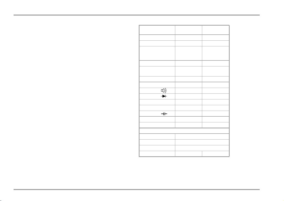
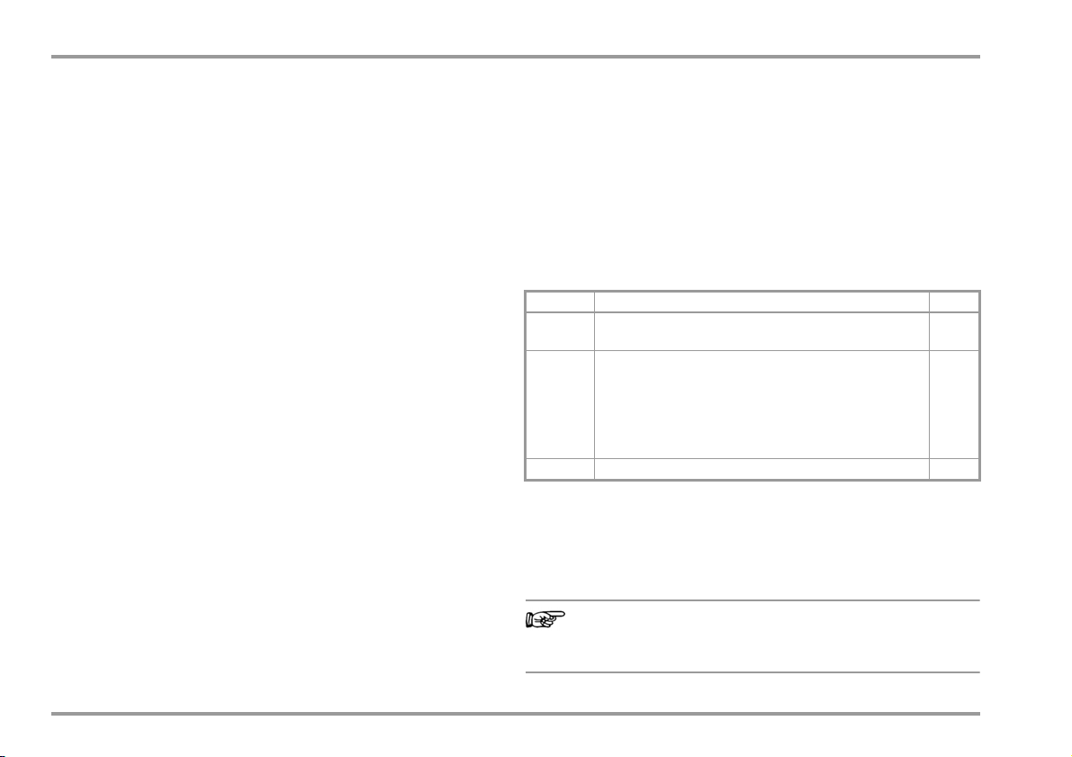
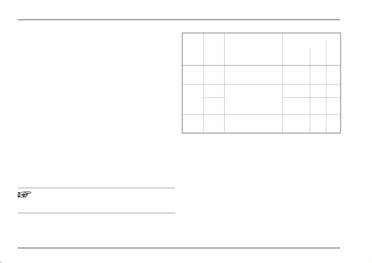
Overview of Features included
Functions Multimeter
V AC / Hz TRMS
V DC
Hz (V AC)
A AC / Hz TRMS
A DC
Hz (A AC)
Resistance
Continuity
Diode ... 6 V
Temperature TC
Temperature RTD
Capacitance
Min-Max / data hold
16 MBit memory
1)
Features
IR Interface
Power pack socket
Protection (housing)
Measuring category
1)
For 46,000 measured values, sampling rate adjustable from 0.1 second
300 V CAT II
to 9 hours
Calibrator /
Simulator
Pulse generator /
frequency
generator
Current sensor /
current sink
IP 65
—
—
—
—
—
—
—
—
—
2 GMC-I Messtechnik GmbH
Page 3

Contact Persons
Accessories (sensors, plug inserts, adapters, consumable materials)
The accessories available for your instrument are checked for
compliance with currently valid safety regulations at regular intervals, and are amended as required for new applications.
Currently up-to-date accessories which are suitable for your measuring instrument are listed at the following web address along
with photo, order number, description and, depending upon the
scope of the respective accessory, data sheet and operating instructions:
www.gossenmetrawatt.com
See also section 11 on page 80.
Product Support
Technical queries (use, operation, software registration)
If required please contact:
GMC-I Messtechnik GmbH
Product Support Hotline
Phone: +49 911 8602-0
Fax: +49 911 8602-709
e-mail: support@gossenmetrawatt.com
Software Enabling for METRAwin 10
GMC-I Messtechnik GmbH
Front Office
Phone: +49 911 8602-111
Fax: +49 911 8602-777
e-mail: info@gossenmetrawatt.com
GMC-I Messtechnik GmbH 3
Page 4

Standard Equipment Contact Persons
Recalibration Service
Our service center calibrates and recalibrates (e.g. after one year as
part of your test equipment monitoring system, prior to use etc.)
all instruments from GMC-I Messtechnik GmbH and other
manufacturers, and offers free test equipment management.
Repair and Replacement Parts Service
Calibration Center* and Rental Instrument Service
If required please contact:
GMC-I Service GmbH
Service Center
Thomas-Mann-Str. 20
90471 Nürnberg · Germany
Phone: +49 911 817718-0
Fax: +49 911 817718-253
e-mail: service@gossenmetrawatt.com
www.gmci-service.com
This address is only valid in Germany. Please contact our representatives or subsidiaries for service in other countries.
* DAkkS Calibration laboratory for measured electrical quantities,
D-K-15080-01-01, accredited in accordance with
DIN EN ISO/IEC 17025
Competent Partner
GMC-I Messtechnik GmbH is certified in accordance with
DIN EN ISO 9001.
Our DAkkS calibration laboratory is accredited by the Deutsche
Akkreditierungsstelle GmbH (National accreditation body for the
Federal Republic of Germany) in accordance with DIN EN ISO/IEC
17025 under registration number D-K-15080-01-01.
We offer a complete range of expertise in the field of metrology:
from test reports and proprietary calibration certificates right on up to
DAkkS calibration certificates.
Our spectrum of offerings is rounded out with free test equipment
management.
As a full service calibration laboratory, we can calibrate
instruments from other manufacturers as well.
Accredited measured quantities: direct voltage, direct current values,
DC resistance, alternating voltage, alternating current values, AC active
power, AC apparent power, DC power, capacitance, frequency and
temperature
4 GMC-I Messtechnik GmbH
Page 5

Contact Persons
GMC-I Messtechnik GmbH 5
Page 6

Table of Contents
Contents Page Contents Page
1 Safety Features and Precautions ....................................... 8
1.1 Use for Intended Purpose ................................................................10
1.2 Meanings of Danger Symbols ..........................................................11
1.3 Meanings of Acoustic Warning Signals ............................................11
2 Operating Overview – Connections, Keys, Rotary Switch, Symbols 12
3 Initial Start-Up .................................................................. 16
3.1 Inserting Batteries or Rechargeable Batteries ...................................16
3.2 Switching the Instrument On ...........................................................16
3.3 Setting the Operating Parameters ....................................................16
3.4 Switching the Instrument Off ...........................................................17
4 Control Functions ............................................................. 18
4.1 Selecting Measuring Functions and Measuring Ranges .....................18
4.1.1 Automatic Range Selection .............................................................18
4.1.2 Manual Measuring Range Selection .................................................18
4.1.3 Quick Measurements ......................................................................19
4.2 Zero Offset / Relative Measurements ...............................................19
4.3 Display (LCD) .................................................................................20
4.3.1 Exceeding the Measuring Range .....................................................20
4.4 Measured Value Storage: DATA (auto-hold / compare) ......................21
4.4.1 Saving Minimum and Maximum Values – Min/Max Function .............22
4.5 Measurement Data Recording .........................................................23
5 Measurements ................................................................. 26
5.1 Switching from the Calibration Function to the Measuring Function ...26
5.2 Voltage Measurement ....................................................................27
5.2.1 Direct Voltage Measurement, V DC .................................................28
5.2.2 Alternating Voltage and Frequency Measurement, V AC and Hz .........29
5.3 Resistance Measurement
5.4 Continuity Test ..............................................................................31
5.5 Diode Testing with Constant Current of 1 mA ..................................32
5.6 Temperature Measurement ............................................................33
5.6.1 Measurement with Thermocouples, Temp TC .................................. 33
5.6.2 Measurement with Resistance Thermometers ..................................34
5.7 Capacitance Measurement ............................................................36
5.8 Current Measurement .................................................................... 37
5.8.1 Direct Current Measurement, A DC .................................................38
5.8.2 Alternating Current and Frequency Measurement,
Direct Connection, mA AC and Hz ................................................... 39
5.8.3 Direct Current Measurement with Current Clamp Sensor, mA DC ......40
5.8.4 AC Measurement with Current Clamp Sensor, A AC and Hz ..............41
5.8.5 Direct and Alternating Current Measurement with Current Clamp
Transformer, mA DC, mA AC and Hz ...............................................42
6 GMC-I Messtechnik GmbH
Page 7

Table of Contents
Contents Page Contents Page
6 Calibration Functions ........................................................ 44
6.1 Switching from the Measuring Function to the Calibration Function ... 44
6.2 Voltage Source [V] ......................................................................... 45
6.3 Pulse, Frequency Generator (positive square-wave pulse) [Hz] .......... 46
6.4 Resistance Simulation [] ..............................................................47
6.5 Temperature Simulation [°C / °F] .................................................... 48
6.5.1 Temperature Simulation for Resistance Thermometers –
RTD Temperature Setting ............................................................... 49
6.5.2 Temperature Simulation for Thermocouples –
TC Temperature Setting .................................................................49
6.6 Current Source and Current Sink [mA] ............................................51
6.6.1 Current Sink – Simulation of a 2-Wire Transmitter .......................... 52
6.6.2 Current Source ............................................................................. 52
6.7 Interval Functions, Ramp Functions ................................................. 53
6.7.1 Interval Sequences – INT Function .................................................. 53
6.7.2 Read-Out a Periodic Ramp – RAMP Function .................................. 56
6.7.3 Dual Mode (simultaneous simulation and measurement) .................. 58
7 Device and Measuring Parameters ...................................60
7.1 Paths to the Various Parameters .................................................... 61
7.2 List of All Parameters .................................................................... 61
7.3 Querying Parameters – InFo Menu (as moving letters) ...................... 62
7.4 Entering Parameters – SETUP Menu ............................................... 62
7.5 Default Settings ............................................................................. 64
8 Interface Operation ...........................................................66
8.1 Activating the Interface ...................................................................66
8.2 Configuring Interface Parameters .................................................... 67
9 Technical Data .................................................................68
10 Maintenance and Calibration ............................................76
10.1 Displays – Error Messages ............................................................ 76
10.2 Batteries ....................................................................................... 76
10.3 Fuse ............................................................................................. 77
10.4 Housing Maintenance .................................................................... 78
10.5 Return and Environmentally Sound Disposal .................................... 78
10.6 Recalibration ................................................................................. 79
10.7 Manufacturer’s Guarantee .............................................................. 79
11 Accessories .......................................................................80
11.1 General ......................................................................................... 80
11.2 Technical Data for Measurement Cables
(scope of delivery: KS29 safety cable set) ........................................ 80
11.3 NA X-TRA Power Pack (not included) .............................................. 80
11.4 Interface Accessories (not included) ................................................ 81
12 Keyword Index ..................................................................82
GMC-I Messtechnik GmbH 7
Page 8
Safety Precautions
1 Safety Features and Precautions
You have selected an instrument which provides you with high
levels of safety.
This instrument fulfills all requirements of applicable European and
national EC directive. We confirm this with the CE mark. The
relevant declaration of conformity can be obtained from
GMC-I Messtechnik GmbH.
The device has been manufactured and tested in accordance
with safety regulations IEC 61010–1/DIN EN 61010–1/
VDE 0411–1. When used for its intended purpose (see page 10),
safety of the operator, as well as that of the instrument, is assured. Their safety is however not guaranteed, if the
instrument is used improperly or handled carelessly.
In order to maintain flawless technical safety conditions, and to assure
safe use, it is imperative that you read the operating instructions
thoroughly and carefully before placing your instrument into service, and
that you follow all instructions contained therein.
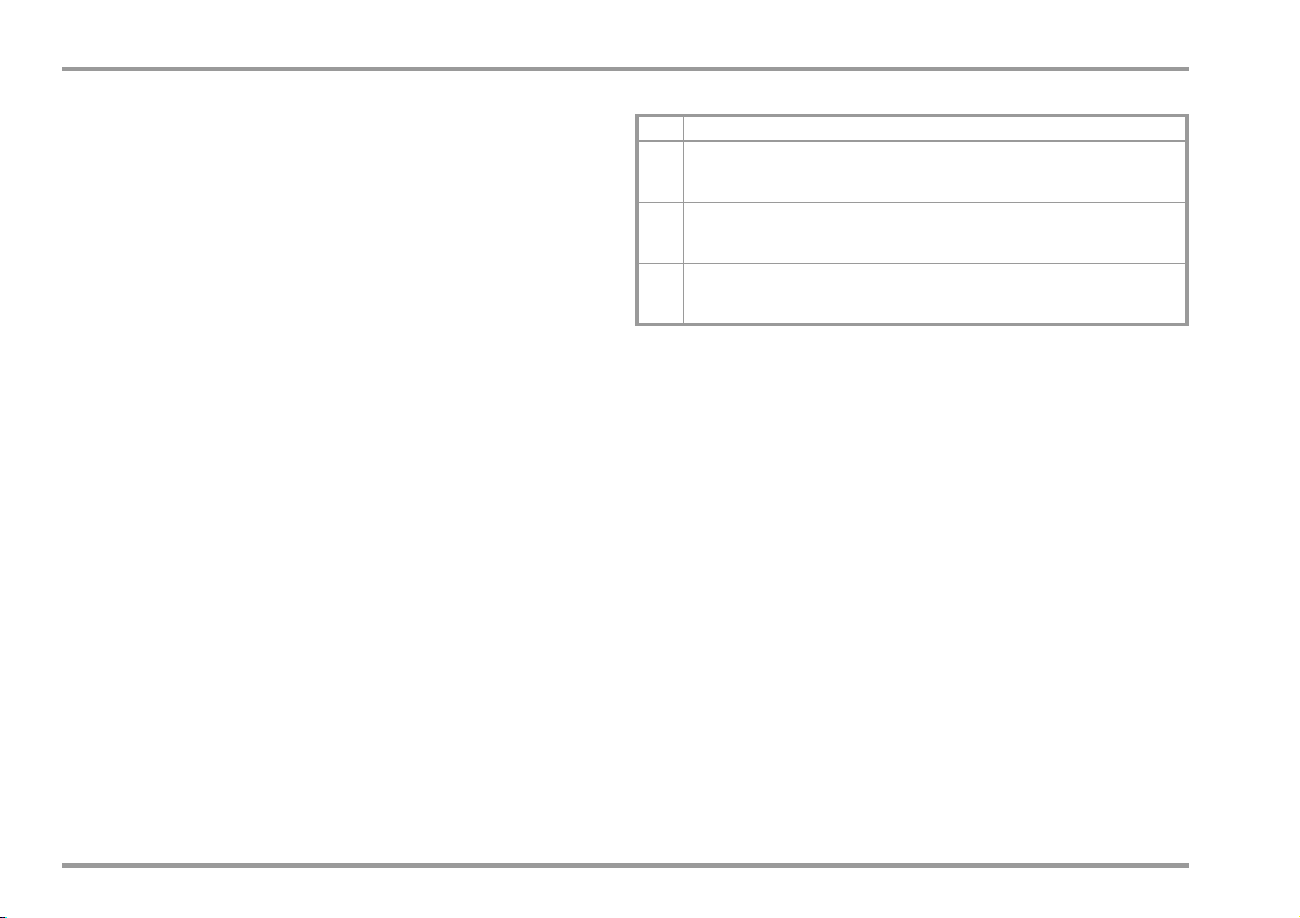
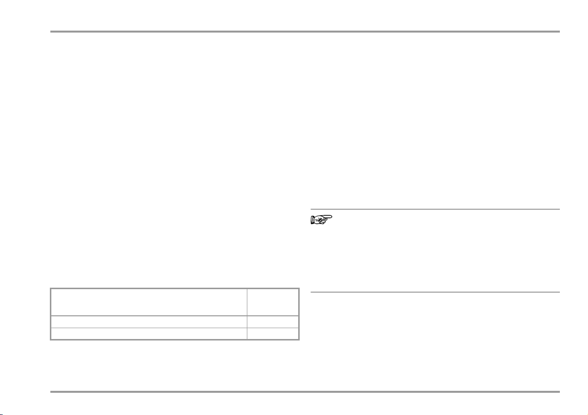
Measuring Categories and their Significance per IEC 61010-1
CAT Definition
Measurements in electrical circuits
I
which are not directly connected to the mains,
e.g. electrical systems in motor vehicles and aircraft, batteries etc.
Measurements in electrical circuits
II
which are directly connected to the low-voltage mains
via plug, e.g. in household, office and laboratory applications etc.
Measurements in building installations:
III
stationary consumers, distributor terminals, devices connected permanently to
the distributor
The measuring category and the maximum rated voltage which
are printed on the device apply to your measuring instrument, e.g.
300 V CAT II.
Refer to section 11.2 regarding use of the measurement cables.
Observe the following safety precautions:
• The multimeter may not be used in potentially explosive
atmospheres.
• The multimeter may only be operated by persons who are
capable of recognizing contact hazards and taking the
appropriate safety precautions. Contact hazards according to
the standard exist anywhere, where voltages of greater than
33 V RMS or 70 V DC may occur. Avoid working alone when
taking measurements which involve contact hazards. Be
certain that a second person is present.
• Maximum permissible voltage
between the voltage measuring sockets or all connector sockets and ground is 300 V for measuring category II.
• Be prepared for the occurrence of unexpected voltages at
devices under test (e.g. defective devices). For example,
capacitors may be dangerously charged.
8 GMC-I Messtechnik GmbH
Page 9
Safety Precautions
Attention!
!
Note
• Make certain that the measurement cables are in flawless
condition, e.g. no damage to insulation, no interruptions in
cables or plugs etc.
• Device functions may not be executed in electrical circuits with
corona discharge (high-voltage).
• Special care is required when measurements are made in HF
electrical circuits. Dangerous pulsating voltages may be
present.
• Measurements under moist ambient conditions are not
permitted.
• Be absolutely certain that the measuring ranges are not
overloaded beyond their allowable capacities. Limit values are
included in section 9, “Technical Data”, in the table entitled
“Measuring Functions and Measuring Ranges” in the
“Overload Capacity” column.
• The multimeter may only be operated with installed batteries or
rechargeable batteries. Dangerous currents and voltages are
otherwise not indicated, and the instrument may be damaged.
• The instrument may not be operated if the fuse cover or the
battery compartment lid has been removed, or if its housing is
open.
• The input for the current measuring range is equipped with a
fuse link. Maximum permissible voltage for the measuring
circuit (= rated voltage of the fuse) is 400 V. Use specified fuses
only (see page 73)! The fuse must have a
breaking capacity of at least 10 kA.
Special Safety Precautions for the Calibrator
• If necessary, use the multimeter section of the instrument to
make sure that no dangerous contact voltages are present in
the signal circuits to which the instrument is to be connected.
• In order to prevent damage to the instrument, observe the
maximum allowable voltage and current values indicated at
the jacks.
With the exception of the resistance simulation and mA SINK
operating modes, the connected signal circuits should not
feed any voltage or current back to the calibrator.
In order to avoid damage to the instrument when interference
voltages are applied (within allowable limit values),
the mA SINK and mA SOURCE circuits are equipped with an fuse,
which makes this circuit highly resistive in the event that
excessive current should occur in case of a fault for the
duration of overloading.
If the calibrator is connected with reversed polarity, a high
current may occur which trips the integrated fuse.
Please observe the following prior to connecting the DUT:
Switch on the instrument and adjust the correct calibrator
function before connecting the DUT. Otherwise, a high
current may flow through the DUT for a short while after
power-on, thus interfering with the fuse test.
GMC-I Messtechnik GmbH 9
Page 10
Safety Precautions
Warning!
Opening of Equipment / Repair
The equipment may be opened only by authorized service personnel to ensure the safe and correct operation of the equipment
and to keep the warranty valid.
Even original spare parts may be installed only by authorized service personnel.
In case the equipment was opened by unauthorized personnel,
no warranty regarding personal safety, measurement accuracy,
conformity with applicable safety measures or any consequential
damage is granted by the manufacturer.
Repair and Parts Replacement
When the instrument is opened, voltage conducting parts may be
exposed. The instrument must be disconnected from the
measuring circuit before performing repairs or replacing of parts.
If repair of a live open instrument is required, it may only be carried out by trained personnel who are familiar with the dangers
involved.
Defects and Extraordinary Strains
If it may be assumed that the instrument can no longer be
operated safely, it must be removed from service and secured
against unintentional use.
Safe operation can no longer be relied upon:
• If the device demonstrates visible damage
• If the instrument no longer functions, or if malfunctioning
occurs
• After long periods of storage under unfavorable conditions,
e.g. humidity, dust or extreme temperature (see
“Ambient Conditions” on page 73).
1.1 Use for Intended Purpose
• The multimeter is a portable device which can be held in the
hand during the performance of measurements.
• Only those types of measurements described in section 5 may
be performed with the measuring instrument.
• The measuring instrument, including measurement cables and
plug-on test probes, may only be utilized within the specified
measuring category (see section 9 and the table on page 8
regarding significance).
• Overload limits may not be exceeded. See technical data on
section 9 for overload values and overload limits.
• Measurements may only be performed under the specified
ambient conditions. See section 9 regarding operating
temperature range and relative humidity.
• The measuring instrument may only be used in accordance
with the specified degree of protection (IP code)
(see section 9).
The instrument may not be operated in explosive
atmospheres, or connected to intrinsically safe electrical
circuits.
10 GMC-I Messtechnik GmbH
Page 11
1.2 Meanings of Danger Symbols
!
(2x)
...
...
Warning concerning a source of danger
(attention: observe documentation!)
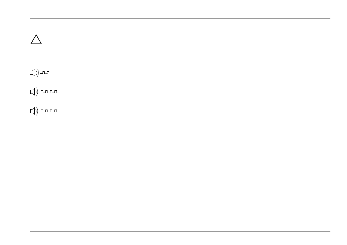
1.3 Meanings of Acoustic Warning Signals
Warning for dangerous voltage at the measurement input:
U > 33 V AC or U > 70 V DC (double acoustic signal)
Warning for excessive current in the 300 mA measuring range:
> 310 mA (intermittent acoustic signal)
Voltage warning: > 310 V (intermittent acoustic signal)
Safety Precautions
GMC-I Messtechnik GmbH 11
Page 12
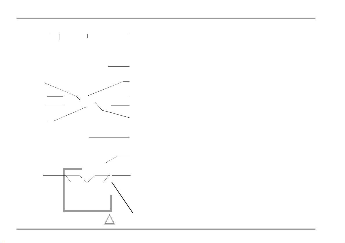
Operating Overview – Connections, Keys, Rotary Switch, Symbols
1
3
4
15
5
6
8
section 4.3
section 3
section 5
section 8
section 7
section 3
ff
12
11
section 6
9
2
section 4.1.2
13
Max. 300 V !
10
14
section 4.1
section 4.4
section 7
section 3
section 7
section 3.1
7
section 1.2
Not a measuring input!
Do not connect external voltage
except for current sink.
!
2
Operating Overview – Connections, Keys, Rotary Switch, Symbols
1 Display (LCD) (see page 13 for significance of symbols)
2 MAN / AUTO Shift key for manual/automatic measuring range selection
Increase parameter values
Operating mode menu: Selection of individual menu entries against
direction of flow
3
ON / OFF | LIGHT
key for switching device and display illumination on and off
4 OUT | ENTER
OUT: Switch calibrator output on and off
Operating mode menu: Acknowledge entry (ENTER)
Increase measuring range or move decimal point to the right (MAN function)
5
6 Rotary switch for measuring functions (white) and calibration functions
(red), (see page 13 for significance of symbols)
7 DAkkS calibration mark
8 Connector jacks for calibrator output
9 Connector jacks for measuring and sensing inputs
10 DATA / MIN / MAX
Key for freezing, comparing and deleting the measured value, and for the
Min-Max function
Decrease values
Operating mode menu: Selection of individual menu entries in the
direction of flow
11 MEASURE / CAL | SETUP
Key for switching between measuring, calibration and menu functions
12 ZERO / SEL | ESC
Key for zero balancing and for selecting double functions
Operating mode menu: Exit current menu level and return to a higher level.
Exit parameters entry function without saving. Pause ramp/interval
Decrease measuring range or move decimal point to the left (MAN function)
13
14 Power pack connector jack
15 Infrared interface
12 GMC-I Messtechnik GmbH
Page 13
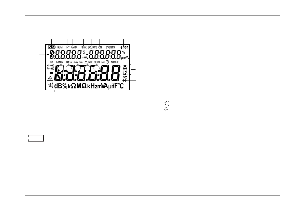
Symbols Used in the Digital Display
1 28
9
14
16
18
654 7
9
3
Battery full
*
Battery OK
*
Battery weak
Battery (almost) dead, U < 1.8 V
Data transmission to / from calibrator active
IR interface in stand-by mode
(ready to receive power-up commands)
Battery Level Indicator
Interface Indicator (with rotary switch setting OFF)
11
13
10
15
22 242120
19
17
23
12
* Calibration function: current I
Sink
possible (U > 2.3 V)
Operating Overview – Connections, Keys, Rotary Switch, Symbols
1 Battery level indicator
2 NUM: Numeric entry of the output signal
3 INT: Interval sequence active
4 RAMP: Ramp function active
5 SINK: Current sink active
6 SOURCE: Current source active
7 ON: Calibrator output active
8 IR: infrared interface indicator
9 Auxiliary display with decimal point and polarity display
10 STORE: memory mode active
11 Selected type of current
12 Transformation ratio (current clamp factor)
13 Diode measurement selected
14 Unit of measure
15 Continuity test with acoustic signal active
16 : Continuous operation (automatic shutdown deactivated)
17 Digital display with decimal point and polarity display
18 RTD: selected nickel or platinum resistance thermometer
19 TC: temperature measurement with thermocouple types B through U
20 MAN: manual measuring range selection active
21 DATA: display memory, “freeze measured value”
22 max/min: Min-Max value storage
23 : relative measurement with reference to offset
24 ZERO: zero balancing active
GMC-I Messtechnik GmbH 13
Page 14
Operating Overview – Connections, Keys, Rotary Switch, Symbols
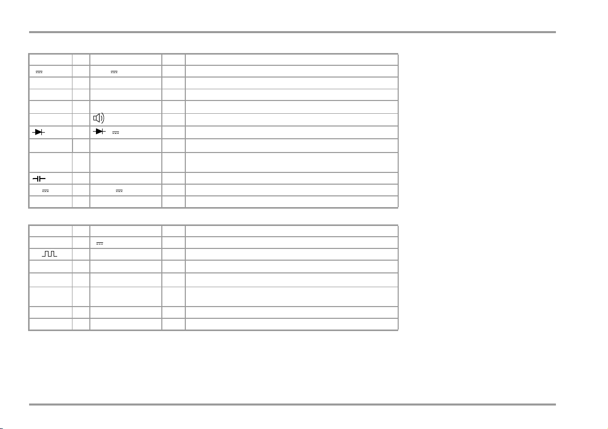
Symbols Used for Rotary Switch Positions
Rotary Switch
V —mV, V DC Direct voltage
V~ 0/2 mV, V ~ AC TRMS Alternating voltage, AC TRMS, full bandwidth
Hz (V) 1 Hz, kHz ~ AC — Voltage frequency, full bandwidth
Temp . TC —
Temp . RTD — C Pt100/1000
mA —μA, mA DC Direct current value
mA~ — μA, mA ~ AC TRMS Alternating current amperage, AC TRMS
SEL
Display ZERO Measuring Function – White Printing
0/2 , k, M(DC) resistance
1 — Continuity test with acoustic signal
—
—nF μF Capacitance
V DC — Diode voltage
C types B ... U
C Ni100/1000
— Temperature, type K thermocouple
Temperature with resistance thermometer
Rotary Switch
V — V DC Direct voltage simulator
Hz — Hz Pulse / frequency generator
Temp . TC —
Temp . RTD — C Pt100/1000
mA — mA Current sink
mA — mA Current sensor
14 GMC-I Messtechnik GmbH
SEL
Display Calibration Function – Red Printing
0/2 (DC) Resistance simulator
C types B ... U
C Ni100/1000
Thermocouple simulator
Resistance thermometer simulator
Page 15
Operating Overview – Connections, Keys, Rotary Switch, Symbols
!
5V/600mA
Serial number
Registration number
Date of calibraion (year – month)
German Accrediation Body GmbH – Calibration lab
XY123
2012-08
D-K-
15080-01-01
User Interface Symbols in the Following Sections
... Scroll through main menu
... Scroll through submenu
Select decimal point
Increase/decrease value
time Submenu/parameter (7-segment font)
1nFo Main menu (7-segment font, boldface)
Symbols on the Device
Warning concerning a source of danger
(attention: observe documentation!)
Ground
CAT II
Overvoltage category II (see also “Measuring Categories
and their Significance per IEC 61010-1” on page 8)
Continuous, doubled or reinforced insulation
▲ IR ▼ Position of the infrared interface, window on the top of
the instrument
See also section 3.1 regarding location of the
power pack adapter socket.
Fuse for current measuring ranges, see section 10.3
This device may not be disposed of with the trash. Further information regarding the WEEE mark can be
accessed on the Internet at
www.gossenmetrawatt.com by entering the search
term WEEE (see also section 10.5).
Calibration mark (blue seal):
See also “Recalibration” on page 79.
EC label of conformity
GMC-I Messtechnik GmbH 15
Page 16

Initial Start-Up – Setup
Attention!
!
Note
3 Initial Start-Up
3.1 Inserting Batteries or Rechargeable Batteries
Be certain to refer to section 10.2 regarding correct battery
installation.
Momentary battery voltage can be queried in the Info menu (see
section 7.3).
Disconnect the instrument from the measuring circuit before
opening the battery compartment lid in order to replace the
batteries.
Operation With Power Pack
(accessory, not included, see section 11.3)
Installed batteries are disconnected electronically if the power
pack is used, and need not be removed from the
instrument. If rechargeable batteries are used, they must be
recharged externally. If the external power supply is switched off,
the device is switched to battery operation without interruption.
3.2 Switching the Instrument On
Switching the Instrument On Manually
➭ Press the ON / OFF | LIGHT key until the display appears.
Power-up is acknowledged with a brief acoustic signal. As
long as the key is held depressed, all of the segments at the
liquid crystal display (LCD) are illuminated.
The LCD is depicted on page 13.
The instrument is ready for use as soon as the key is released.
Display Illumination
After the instrument has been switched on, background
illumination can be activated by briefly pressing the
ON / OFF | LIGHT key. Illumination is switched back off by once
again pressing the same key, or automatically after approximately
1 minute.
Switching the Instrument On with a PC
The multimeter is switched on after transmission of a data block
from the PC, assuming that the “irStb” parameter has been set to
“ir on” (see section 7.4).
However, we recommend using the power saving mode “ir off”.
Electrical discharge and high frequency interference may
cause incorrect displays to appear, and may disable the
measuring or calibrating sequence.
Disconnect the device from the measuring circuit. Switch the
instrument off and back on again in order to reset. If the
problem persists, briefly dislodge the battery from the
connector contacts (see also section 10.2).
3.3 Setting the Operating Parameters
Setting Time and Date
See the “t iME” and “dAtE” parameter in section 7.4.
16 GMC-I Messtechnik GmbH
Page 17

Initial Start-Up – Setup
ON / OFF
LIGHT
OUT
ENTER
3.4 Switching the Instrument Off
Switching the Instrument Off Manually
➭ Press the ON / OFF | LIGHT key until 0FF appears at the display.
Shutdown is acknowledged with a brief acoustic signal.
➭ Complete shutdown of all functions including the IR interface is
accomplished by turning the rotary switch to OFF.
In the calibration function, the output can be shut down
separately with the OUT | ENTER key.
Shutdown is acknowledged with a brief acoustic signal.
Exceptions:
If a dangerous voltage is present at the input, shutdown is blocked and an acoustic signal is generated. The instrument must be
disconnected from the measuring cables before being switched
off.
Automatic Shutdown – DMM
The instrument is switched off automatically if the measured value
remains unchanged for a long period of time (maximum measured
value fluctuation of approx. 0.8% of the measuring range per
minute, or 1 C or 1 F per minute), and if none of the keys or the
rotary switch have been activated before a selected period of time
in minutes has elapsed (see “APoFF” parameter on page 63).
Shutdown is acknowledged with a brief acoustic signal.
Exceptions:
Transmission and memory mode operation, continuous operation
and whenever a dangerous voltage is applied to the input
(U > 33 V AC or U > 70 V DC).
Automatic Shutdown – Calibrator
The device is switched off automatically after the selected time,
“APoFF” (see page 63), has elapsed. The display is shut down
after one additional minute, assuming that neither the rotary
switch nor any of the keys are activated.
The display can also be switched off by pressing the
ON / OFF | LIGHT key.
Automatic shutdown of the outputs is disabled in the continuous
operation mode (AP oFF = on).
Disabling Automatic Shutdown
The instrument can be set to continuous operation.
➭ Simultaneously press the
and keys to this end.
or
➭
Select AP oFF = on in the setup menu (see “
APoFF
” on page 63.)
Continuous operation is indicated at the display with the
symbol.
The “Continuous On” setting can only be canceled by changing the respective parameter, and not by switching the instrument off if automatic
shutdown has been deactivated in the setup menu (see “APoFF” on page
63).
GMC-I Messtechnik GmbH 17
Page 18
Control Functions
Note
4 Control Functions
4.1 Selecting Measuring Functions and Measuring Ranges
The desired measuring function (white symbols) is selected with
the rotary switch. Double functions like Hz and continuity testing
are selected with the OUT | ENTER key.
4.1.1 Automatic Range Selection
The multimeter is equipped with auto-ranging for all measuring
functions except for temperature measurement, and diode and
continuity testing. Auto-ranging is active as soon as the
instrument is switched on. The instrument automatically selects
the measuring range which allows for highest possible resolution
of the applied quantity. When the instrument is switched to
frequency measurement, the previously selected voltage
measuring range remains active.
AUTO-Range Function
The multimeter is switched automatically to the next higher range
at (30,999 d + 1 d 31,000 d) and to the next lower range at
(2700 d - 1 d 2699 d).
Exception, capacitance measurement:
The multimeter is switched automatically to the next higher range
at (3099 d + 1 d 310 d) and to the next lower range
at (270 d - 1 d 2699 d).
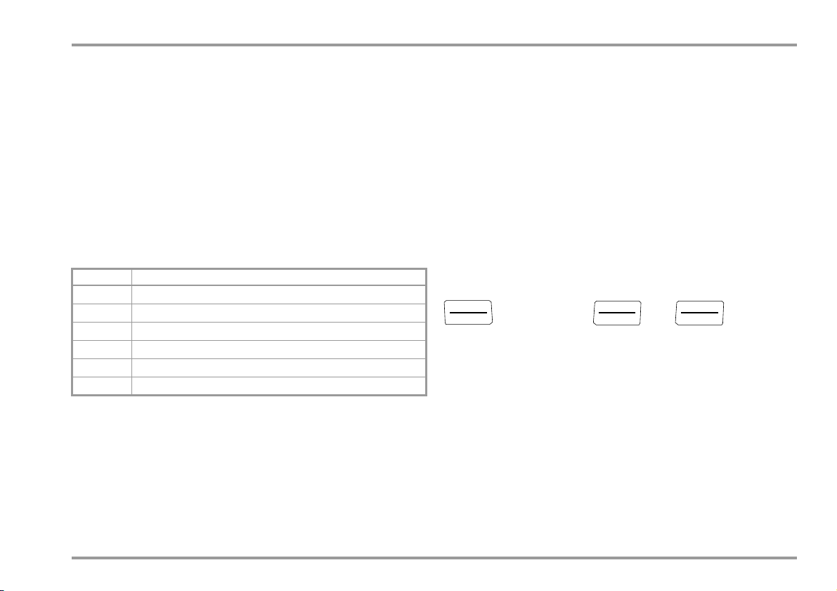
4.1.2 Manual Measuring Range Selection
Auto-ranging can be deactivated and measuring ranges can be
selected manually in accordance with the following table by
pressing the MAN / AUTO button.
The desired measuring range can then be selected with the
scroll key.
or
The instrument is automatically returned to range selection when
the MAN / AUTO key is pressed, the rotary switch is activated or the
instrument is switched off and back on again.
Overview: Auto-Ranging and Manual Range Selection
Function Display
MAN / AUTO
Range switching sequence for:
V
: 60 mV* 300 mV* 3 V 30 V 300 V
or
MAN / AUTO
* Via manual measuring range selection only
** The momentary measured value is used as a reference point during zero
balancing, and is subtracted from future measured values.
Maximum correction is 50% of the measuring range. If the measuring
range is changed with the help of the MAN key, the ZERO function
remains active (at the display and in memory).
Hz: 300 Hz
:
300 3 k 30 k
A:
300A 3 mA 30 mA 300 mA
30 nF 300 nF 3F 30F 300F
F:
Return to automatic measuring range selection —
Manual mode active:
Utilized measuring range is fixed
3 kHz 30 kHz 300 kHz
300 k
3 M
30 M
MAN
MAN
Use short or shielded measurement cables in case of
high-impedance resistance (3 M or 30 M range).
18 GMC-I Messtechnik GmbH
Page 19
Control Functions
Note
4.1.3 Quick Measurements
Measurements performed using a suitable fixed measuring range
are executed more quickly than those which utilize automatic
range selection. Quick measurement is made possible with the
following two functions:
• Manual measuring range selection, i.e. selection of the measuring
range with the best resolution (see section 4.1.2)
or
•With the DATA function (see section 4.4). In this way, the
appropriate measuring range is selected automatically after the
first measurement, and the second measurement is executed
more quickly.
The selected measuring range remains active for the subsequent
series of measurements with these two functions.
4.2 Zero Offset / Relative Measurements
Zero balancing or a reference value for relative measurements can
be stored to memory depending upon deviation from the zero
point:
Deviation from zero point
– with short-circuited measurement cables for V, , mA, RTD
– with open input for capacitance unit of measure F
0 to 200 digits ZERO
> 200 to 15000 digits
Display
The relevant reference or correction value is deducted individually
for the respective measuring function as an offset from all future
measurements and remains in memory until deleted, or until the
multimeter is switched off.
Zero balancing and reference value adjustment can be used for
auto-ranging, as well as for manual measuring range selection.
Zero Balancing
➭ Plug the measuring cables into the instrument and connect the
free ends to each other, except for capacitance measurement
in which case the ends of the cables are not connected to
each other.
➭ Briefly press the ZERO / SEL | ESC key.
The instrument acknowledges zero balancing with an acoustic
signal, and the “D ZERO” symbol appears at the LCD. The
value measured at the moment the key is pressed serves as a
reference value.
➭ Zero balancing can be cleared by once again pressing the
ZERO / SEL | ESC key.
As a result of TRMS measurement, the multimeter displays a
residual value of 1 to 30 digits with short-circuited
measurement cables as the zero point for V AC/I AC
measurements (non-linearity of the TRMS converter). This
has no influence on specified accuracy above 2% of the
measuring range (or 3% in the mV range).
GMC-I Messtechnik GmbH 19
Page 20

Control Functions
4.3 Display (LCD)
4.3.1 Exceeding the Measuring Range
Measured Value, Unit of Measure, Type of Current, Polarity
The measured value appears at the digital display with decimal
and plus or minus sign. The selected unit of measure and current
type are displayed as well. A minus sign appears to the left of the
value during the measurement of zero-frequency quantities, if the
plus pole of the measured quantity is applied to the “” input.
Overranging
If the upper range limit of 31,000 digits is exceeded “0L” (overload)
appears at the display.
Exceptions: “0L” appears as of 3100 digits for capacitance
measurement, and as of 61,000 digits for diode testing.
20 GMC-I Messtechnik GmbH
Page 21
Note
V, mA, Hz
t [s]
100%
10%
Activated
Reactivated
Save
Save
30,000 Digits
of Measuring Range
F
31,000 Digits
OL
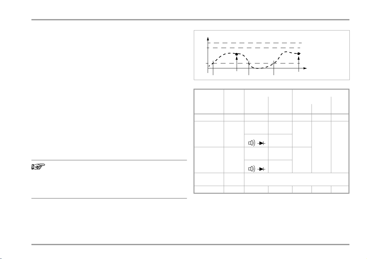
4.4 Measured Value Storage: DATA (auto-hold / compare)
An individual measured value can be automatically “frozen” with
the DATA function (auto-hold). This is useful, for example, when
contacting the measuring points with the test probes requires
your full attention. After the measuring signal has been applied
and the measured value has settled in in accordance with the
“condition” listed in the table below, the measured value is frozen
in the top left section of the auxiliary display as well as the associated „freeze time“ in the top right section and an acoustic signal is
generated. The test probes can now be removed from the measuring points, and the measured value can be read from the digital display. If the
measuring signal falls below the value specified in the table, the
function is reactivated for storage of the next value.
Measured Value Comparison (DATA Compare)
If the currently frozen value deviates from the first saved value by
less than 100 digits, the acoustic signal is generated twice. If
deviation is greater than 100 digits, only a brief acoustic signal is
generated.
However, when the digital display is “frozen”, the decimal
point is fixed as well (fixed measuring range, symbol: MAN).
The selected measuring range should not be manually
changed as long as the DATA function is active.
The DATA function is deactivated by pressing and holding the
DATA/MIN/MAX key (approx. 1 second), when the measuring function is changed or when the instrument is switched off and back
on again.
Control Functions
Condition Response from Instrument
DATA
Function
Activate Brief Once
Save
(stabilized
measured
value)
Reactivate
Change to
Min/Max
Exit Long
1)
Reactivation results from falling short of specified measured value limits.
2)
Two acoustic signals are generated the first time a measured value is
saved as a reference value. For subsequent data hold, two acoustic signals are only generated if the currently frozen value deviates from the first
saved value by less than 100 digits.
Key: MV = measured value, MR = measuring range
Data/
Min/Max
1)
Measuring
Key
Brief See table, section 4.4.1
Function
V, A, F, Hz,
RTD TC
V, A, F, Hz,
RTD TC
Measuring
Signal
> 10%
rdg.
0L
< 10%
rdg.
= 0L
Auxiliary Display Acous-
top left top right
frozen
MV is
indicated
indicated
Stored
MV
Is deleted Is deleted
„Freeze
time“ is
tic Sig-
Once
Twi ce
Tw ic e
nal
2)
GMC-I Messtechnik GmbH 21
Page 22
Control Functions
Note
Example
The voltage measuring range is set manually to 10 V.
The first measured value is 5 V and is stored to memory because
it is greater than 10% of the measuring range. As soon as the
measured value drops to less than 10% of the measuring range,
i.e. amounts to less than 1 V which corresponds to removal of the
test probes from the measuring point, the instrument is ready to
store a new value.
4.4.1 Saving Minimum and Maximum Values – Min/Max Function
Minimum and maximum measured values applied to the
measuring instrument’s input after the Min/Max function has been
activated can be “frozen” at the display. The most important use
of this function is the determination of minimum and maximum
values during long-term measured value observation.
The Min/Max function can be activated in all measuring functions.
Apply the measured quantity to the instrument and set the mea-
suring range with the MAN / AUTO key before activating the Min/
Max function.
The Min/Max function is deactivated by pressing and holding the
DATA/MIN/MAX key (approx. 1 second), when the measuring function is changed or when the instrument is switched off and back
on again.
Min-Max
Function
Activate
and save
Save and
display
Stop Long Are deleted
Data/
Min/Max
Key
1
1 x brief Are saved
Brief
2
Brief
Min. and Max.
Measured Values
Storage continues in background, new min. and max.
values are displayed together
with the point in time of
occurrence.
Response from Instrument
Display
Digital
Measured
Valu e
Current
measured
value
Saved min.
value
Saved max.
value
Current
measured
value
Max.
Min.
Min.
Min.
Max.
Is
deleted
Acous
tic
Sig-
nal
Once
Once
Once
Twi ce
As opposed to the DATA function, the Min/Max function can
also be used for temperature measurement.
22 GMC-I Messtechnik GmbH
Page 23
Control Functions
MEAS / CAL
SETUP
OUT
ENTER
OUT
ENTER
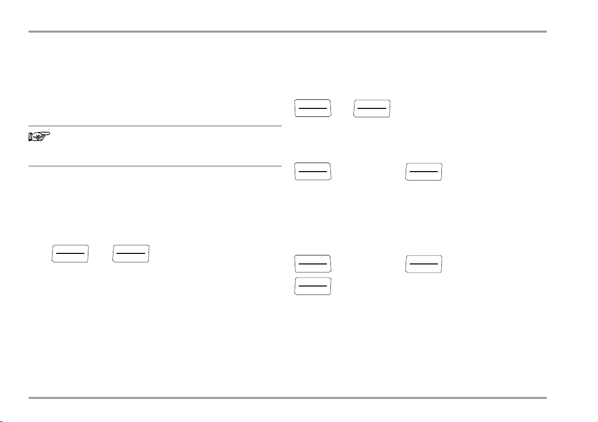
4.5 Measurement Data Recording
The multimeter is capable of recording measurement data using
an adjustable sampling rate for long periods of time in the form of
measurement series. Data are stored to a battery backed
memory module, and are retained even after the multimeter is
switched off. The system acquires measured values relative to
real-time.
Stored measured values can subsequently be read out with the
help of METRAwin 10 software. The only prerequisite is a PC which
is connected by means of an interface cable to the
USB X-TRA bidirectional interface adapter, which is plugged onto
the digital multimeter. See also section 8.
Memory Parameters Overview
Parameter Page: Header
CLEAr
EMpty
0CCvP
rAtE
StArt
StoP
24: Clear Memory
24: Clear Memory – appears after CLEAr
24: Querying Memory Occupancy
62: rAtE – set the sampling rate
23: Starting Recording via Menu Functions
24: Ending Recording
The STORE Menu Function
➭ First set the sampling rate for memory mode operation
(see section 7.4 the rAtE parameter), and then start memory
mode operation.
➭ Select the desired measuring function and an appropriate
measuring range.
➭ Check the battery charge level before starting long-term
measurement recordings (see section 7.3).
Connect the NA X-TRA power pack if applicable.
Starting Recording via Menu Functions
➭ Switch to the “SETUP” mode by pressing MEAS / CAL | SETUP and
select the “StorE” menu.
... StorE StArt StorE
1nFo
STORE
➭ Memory mode operation is started by acknowledging with
OUT | ENTER. The small STORE segment appears, indicating that
the memory mode has been activated.
“Store” appears at the digital display, indicating that you’re still
in the menu function.
➭ Press MEAS / CAL | SETUP in order to return to the measuring
function.
GMC-I Messtechnik GmbH 23
Page 24
Control Functions
Note
OUT
ENTER
OUT
ENTER
MEAS / CAL
SETUP
OUT
ENTER
MEAS / CAL
SETUP
OUT
ENTER
MEAS / CAL
SETUP
OUT
ENTER
OUT
ENTER
During Recording
In order to be able to observe measured values during recording,
switch to the measuring function by pressing
MEAS / CAL | SETUP. After pressing MEAS / CAL | SETUP once again,
the display is returned to the 1nfo menu where memory
occupancy can be queried with the 0CuPP parameter.
As soon as memory is full, the “Store” segment is cleared
from the display.
A new memory block is created when another measuring function
is selected with the rotary switch or the OUT | ENTER key. Data storage then continues automatically.
Ending Recording
store stop store
➭ Press MEAS / CAL | SETUP in order to return to the measuring
function.
➭ Memory mode operation can also be exited by switching the
multimeter off.
Querying Memory Occupancy
Memory occupancy can be queried during recording with the
help of the “1nFo” menu (see also section 7.3).
Memory occupancy range: 000.1% to 099.9%.
1nFo
bAtt:
...
0CCvP
%:
017.4
%
Memory occupancy can be queried before recording is started via
the “1nfo” menu.
... StorE 017.4 % StArt
1nFo
Clear Memory
This function deletes all measured values from memory! This
function cannot be executed during memory mode operation.
... StorE StArt
1nFo
Clear
yes
empty StorE
24 GMC-I Messtechnik GmbH
Page 25

Control Functions
GMC-I Messtechnik GmbH 25
Page 26
V/Hz, , Temperature, and A/Hz Measurements
0230.6
V
AC
0050.0
Hz
V~
Hz
MEAS/CAL
SETUP
V~
CALIBRATOR MULTIMETER
Hz
15.000 calibV
Long
–+ +
–+ +
–+ +
5 Measurements
5.1 Switching from the Calibration Function to the Measuring Function
If any calibration function is active, press and hold the
MEASURE / CAL | SETUP key in order to activate the measuring function.
26 GMC-I Messtechnik GmbH
Page 27

V/Hz, , Temperature, and A/Hz Measurements
5.2 Voltage Measurement
Notes Regarding Voltage Measurement
• The multimeter may only be operated with installed batteries or
rechargeable batteries. Dangerous voltages are otherwise not
indicated, and the instrument may be damaged.
• The multimeter may only be operated by persons who are capable of recognizing contact hazards and taking the appropriate
safety precautions. Contact hazards exist anywhere, where
voltages of greater than 33 V (RMS) may occur.
The test probes may only be only gripped up to the finger
guard. Do not touch the metallic test probes under any
circumstances.
• Avoid working alone when taking measurements which involve
contact hazards. Be certain that a second person is present.
• Maximum permissible voltage between the connector sockets,
(9 and 10) and ground (8) is 300 V for measuring category II.
• Be prepared for the occurrence of unexpected voltages at
devices under test (e.g. defective devices). For example,
capacitors may be dangerously charged.
• No measurements may be made with this instrument in
electrical circuits with corona discharge (high-voltage).
• Special care is required when measurements are made in HF
electrical circuits. Dangerous pulsating voltages may be
present.
• Be absolutely certain that the measuring ranges are not
overloaded beyond their allowable capacities. Limit values are
included in section 9, “Technical Data”, in the table entitled
“Measuring Functions and Measuring Ranges” in the
“Overload Capacity” column.
Scope of Functions, Voltage Measurement
Function
V AC / Hz TRMS
V DC
Frequency response, V AC
20 kHz
Scope of Functions, Current Measurement via Current Clamp Sensor
Function
Transformation Ratio
A AC / Hz
A DC
Hz (A AC)
... 10 kHz
GMC-I Messtechnik GmbH 27
Page 28

V/Hz, , Temperature, and A/Hz Measurements
Note
Note
MEAS / CAL
SETUP
OUT
ENTER
OUT
ENTER
OUT
ENTER
–+ +
– (+)
+ (–)
020.00
V
DC
V
V
> 33 V AC or > 70 V DC:
MB 300 V > 310 V:
Warnings regarding dangerous voltages:
Measuring ranges:
...
(2x)
V= : 60mV / 30mV /
3 V / 30 V / 300 V
5.2.1 Direct Voltage Measurement, V DC
Set the CL iP parameter to 0FF in the current clamp setup
menu.
Otherwise all measured values are displayed in mA,
corrected by the amount resulting from the selected transformation ratio for an interconnected current clamp sensor.
1nFo ... SET time ... CL IP
1 / 10/100/1000 / 0ff
➭ In accordance with the voltage to be measured, turn the rotary
switch to V .
➭ Connect the measurement cables as shown.
The “” connector jack should be grounded.
An intermittent acoustic signal warns the operator if the
measured value exceeds the upper range limit in the
300 V range.
Make sure that a current measuring range (“A”) has not been activated, when the multimeter is connected for voltage measurement!
If the fuse’s blowing limits are exceeded as a result of operator
error, both the operator and the instrument are in danger!
With the rotary switch in the V position, the multimeter is always in
the 1 V measuring range immediately after it is switched on. As
soon a the MAN / AUTO key is pressed, and assuming the
measured value is less than 310 mV, the multimeter is switched to
the mV measuring range.
28 GMC-I Messtechnik GmbH
Page 29

5.2.2 Alternating Voltage and Frequency Measurement, V AC and Hz
Note
–+ +
max. 300 V (< 10 kHz)
V~: 60mV ... 300 V
Hz: 300 Hz ... 300 kHz
~
max. 100 V (> 10 kHz)
P
max
= 3 x 10⁶ V x Hz
Measuring ranges:
for U > 100 V
0230.6
V
AC
050.03
Hz
AC
V~
Hz
V~
ZERO/SEL
ESC
> 33 V AC or > 70 V DC:
MB 300 V > 310 V:
Warnings regarding dangerous voltage:
(2x)
...
➭ In accordance with the voltage or frequency to be measured,
turn the rotary switch to V~.
➭ Connect the measurement cables as shown.
The “” connector jack should be grounded.
Note: See note regarding the CL iP parameter in section 5.2.1.
Voltage Measurement
V/Hz, , Temperature, and A/Hz Measurements
An intermittent acoustic signal warns the operator if the
measured value exceeds the upper range limit in the
300 V range.
Make sure that a current measuring range (“mA”) has not been
activated, when the multimeter is connected for voltage measurement! If the fuse’s blowing limits are exceeded as a result of operator error, both the operator and the instrument are in danger!
➭ Repeatedly press the multifunction key OUT | ENTER until the
unit of measure V appears at the display.
Frequency measurement
➭ Connect the measured quantity in the same way as for voltage
➭ Manually select the measuring range for the voltage amplitude.
➭ Repeatedly press the multifunction key OUT | ENTER until the
GMC-I Messtechnik GmbH 29
measurement.
When the instrument is switched to frequency measurement,
the previously selected voltage measuring range remains active.
unit of measure Hz appears at the display.
Lowest measurable frequencies and maximum allowable
voltages are included in section 9, “Technical Data”.
Page 30

V/Hz, , Temperature, and A/Hz Measurements
Note
–+ +
R
x
R
x
0V !
!
000.00
k
300 30 M
Measuring ranges:
Voltage Comparator for Displaying Dangerous Voltage
The input signal or measuring signal is checked by a voltage
comparator for dangerous peaks.
Where U > 33 V AC or U > 70 V DC, two acoustic signals are
generated.
5.3 Resistance Measurement
➭ Disconnect supply power from the electrical circuit of the
device to be measured, and discharge all high-voltage
capacitors.
➭ Make sure that the device under test is voltage-free.
Interference voltages distort measurement results!
Refer to section 5.2.1 regarding testing for the absence of voltage with the help of the direct voltage measurement.
➭ Set the rotary switch to “”.
➭ Connect the device under test as shown.
Use short or shielded measurement cables in the case of
high-impedance resistance.
Improving Accuracy by means of Zero Balancing
Cable resistance and contact resistance can be eliminated in all
measuring ranges by means of zero balancing (see section 4.2).
Maximum correction amounts to 50% of the measuring range.
30 GMC-I Messtechnik GmbH
Page 31

5.4 Continuity Test
MEAS / CAL
SETUP
OUT
ENTER
OUT
ENTER
OUT
ENTER
–+ +
0V !
!
0000.8
R < 1, 10, 20, 30, 40, ... 300
ZERO/SEL
ESC
0000.8
...
➭ Disconnect supply power from the electrical circuit of the
device to be measured, and discharge all high-voltage
capacitors.
➭ Make sure that the device under test is voltage-free.
Interference voltages distort measurement results!
➭ Set the rotary switch to .
➭ Press the SEL key.
➭ Connect the conductor path under test as shown.
V/Hz, , Temperature, and A/Hz Measurements
Depending upon the selected limit value, the multimeter
generates a continuous acoustic signal in the case of continuity or
short-circuiting, i.e. at a value of less than the selected limit value.
“0L” appears at the display in the case of an open connection.
The limit value can be adjusted in the “SET” menu (see also
section 7.4):
1nFo
1, 10, 20, 30, 40, ... 300
(10 = default setting)
GMC-I Messtechnik GmbH 31
... SET time ... bEEP
Page 32

V/Hz, , Temperature, and A/Hz Measurements
Attention!
!
Note
–+ +
Forward Direction Reverse Direction
0V !
0.654
0.L
to 6 V
Measuring range:
+
–
!
1.8569
V
DC
5.5 Diode Testing with Constant Current of 1 mA
➭ Disconnect supply power from the electrical circuit of the
device to be measured, and discharge all high-voltage
capacitors.
➭ Make sure that the device under test is voltage-free.
Interference voltages distort measurement results!
Refer to section 5.2.1 regarding testing for the absence of voltage with the help of the direct voltage measurement.
➭ Set the rotary switch to .
➭ Connect the device under test as shown.
Observe open-circuit voltage of 7 V during diode testing.
Circuits must be laid out accordingly.
Forward Direction and Short-Circuit
The instrument displays forward voltage in volts (display:
4 places). As long as voltage drop does not exceed the maximum
display value of 6 V, several series connected components or
reference diodes can be tested with a small reference voltage and
Z-diodes.
Reverse Direction and Interruption
The measuring instrument indicates overload 0L.
Resistors and semiconductor paths connected in parallel to
the diode distort measurement results!
32 GMC-I Messtechnik GmbH
Page 33

5.6 Temperature Measurement
Note
Note
MEAS / CAL
SETUP
OUT
ENTER
OUT
ENTER
OUT
ENTER
–+ +
Temp
TC
100.5
C
TC
TE (TC)
1
:
23
.
5
TC
Temperature measurement is performed with a thermocouple
(accessory, not included), which is connected to the voltage input. Alternatively, a resistance thermometer can be used.
Selecting the Unit of Measure for Temperature
V/Hz, , Temperature, and A/Hz Measurements
The internal reference temperature (temperature of the
internal reference junction) is measured by a temperature
sensor inside of the instrument. This may be somewhat
above room temperature as a result of internal heat-up, or
moving from warmer to colder surroundings or vice versa.
1nFo
... setup time ...
temp unit °C / °F
(°C = default setting)
5.6.1 Measurement with Thermocouples, Temp TC
➭ Set the rotary switch to “Temp
The last selected temperature sensor remains in memory
and is accordingly displayed.
➭ The reference temperature is measured at the internal
reference junction. It is shown in the right-hand auxiliary display
or else can be queried (see parameter “1tEMP” in section 7.3
regarding querying).
GMC-I Messtechnik GmbH 33
”.
TC
➭ Connect the sensor to the two accessible jacks. The
instrument displays the measured temperature using the
selected unit of measure.
Page 34

V/Hz, , Temperature, and A/Hz Measurements
5.6.2 Measurement with Resistance Thermometers
➭ Set the rotary switch to “Temp
RTD
”.
The last selected resistance thermometer type remains in memory
and is accordingly displayed.
There are two different ways to compensate for cable resistance:
Automatic Compensation
➭ Press and hold the ZERO / SEL | ESC key.
The “short leads” prompt appears at the display.
If you prefer to enter cable resistance directly, you can skip the
following paragraph.
➭ Short circuit the measuring instrument’s connector cables.
Meas rLEADS appears at the display. A value of “000.00” settles
in. After pressing the OUT | ENTER key, automatic compensation
of cable resistance is activated for all subsequent
measurements.
The short-circuit can now be eliminated, and the
device is ready for use.
Entering Cable Resistance
➭ Press the ZERO / SEL | ESC key once again in the automatic
compensation menu.
➭ Enter the known resistance of the connector cables with the
scroll keys:
Select the digit to be changed with the
the respectively selected digit with the
keys, and change
keys. The default
value is 0.43 . Values can be selected within a range of 0 to
50 .
➭ Upon pressing the OUT | ENTER key, the selected value is
activated and the display is returned to the measuring function.
Cable resistance is taken into consideration for future
measurements, and appears at the top left of the
measurement display. Cable resistance remains in memory
even after the instrument has been switched off.
34 GMC-I Messtechnik GmbH
Page 35

V/Hz, , Temperature, and A/Hz Measurements
–+ +
MULTIMETER
100.5
C
Pt1000
RTD
001.00
short leads
Enter cable resistance
OUT
ENTER
ZERO/SEL
ESC
ZERO/ SEL
ESC
OUT
ENTER
00.4
meas rleads
set leads
Temp
RTD
RTD
Long
Pt100
ZERO/SEL
ESC
MAN / AUTO
DATA/MIN/MAX
Pt1000
Ni100
Ni1000
OUT
ENTER
R < 50
R < 50
RL 0.4
GMC-I Messtechnik GmbH 35
Page 36

V/Hz, , Temperature, and A/Hz Measurements
Note
–+ +
0V !
!
10.38
F
+
–
+
–
30 nF ... 300 F
Measuring range:
5.7 Capacitance Measurement
➭ Disconnect supply power from the electrical circuit of the
device to be measured, and discharge all high-voltage
capacitors.
➭ Make sure that the device under test is voltage-free.
Capacitors must always be discharged before measurement is
performed.
Interference voltages distort measurement results!
Refer to section 5.2.1 regarding testing for the absence of
voltage with the help of the direct voltage measurement.
➭ Set the rotary switch to “ ”.
➭ Connect the (discharged!) device under test to the sockets
with the measurement cables as shown.
The “–” pole of polarized capacitors must be connected to
the “” jack.
Resistors and semiconductor paths connected in parallel to
the capacitor distort measurement results!
Improving Accuracy by means of Zero Balancing
Cable capacitance can be eliminated in all measuring ranges by
means of zero balancing (see section 4.2). Maximum correction
amounts to 50% of the measuring range.
36 GMC-I Messtechnik GmbH
Page 37

V/Hz, , Temperature, and A/Hz Measurements
5.8 Current Measurement
Notes Regarding Current Measurement
• The multimeter may only be operated with installed batteries or
rechargeable batteries. Dangerous currents are otherwise not
indicated, and the instrument may be damaged.
• Set up the measuring circuit in a mechanically secure fashion,
and secure it against inadvertent breaks. Select conductor
cross-sections and lay out connections such that they do not
overheat.
• An intermittent acoustic signal (250 ms on, 250 ms off) warns
of current which exceeds 310 mA in the 300 mA range.
• The input for the current measuring range is equipped with a
fuse link. Maximum permissible voltage for the measuring
circuit (= rated voltage of the fuse) is 400 V.
Use specified fuses only! The fuse must have a breaking
capacity of at least 10 kA.
• If the fuse for the active current measuring range blows, “FUSE”
appears at the digital display, and an acoustic signal is
generated at the same time.
• If a fuse should blow, eliminate the cause of overload before
placing the instrument back into service!
• Fuse replacement is described in section 10.3.
• Be absolutely certain that the measuring ranges are not
overloaded beyond their allowable capacities. Limit values are
included in section 9, “Technical Data” in the table entitled
“Measuring Functions and Measuring Ranges” in the “Overload Capacity” column.
Scope of Functions, Current Measurement, Direct Connection
Function
mA AC / Hz ~ 0.3 mA
A DC 0.3 mA
400 V fuse
3/30/300 mA
3/30/300 mA
Scope of Functions, Current Measurement via Current Clamp Sensor
Function
Transformation Ratio
A AC / Hz
A AC+DC
A DC
Hz (A AC)
—
—
—
—
... 10 kHz
GMC-I Messtechnik GmbH 37
Page 38

V/Hz, , Temperature, and A/Hz Measurements
–+ +
~
R
x
~
R
x
1
3
2
I > 310 mA
!
mA
003.50
A
DC
mA
0.3 mA / 3 mA
30 mA / 300 mA
8.8.8.8.8
!
Current
Measuring ranges:
Current measurement only
with batteries installed!
MR 300 mA
...
5.8.1 Direct Current Measurement, A DC
➭ First disconnect supply power from the measuring circuit or
the power consumer (1), and discharge any capacitors.
➭ Set the rotary switch to mA .
➭ Safely connect the measuring instrument (without contact
resistance) in series to the power consumer (2) as shown.
➭ Switch supply power to the measuring circuit back on (3).
➭ Read the display. Make a note of the measured value if the
instrument is not being operated in the memory mode or the
transmission mode.
➭ Disconnect supply power from the measuring circuit or the
power consumer (1) once again, and discharge any
capacitors.
➭ Remove the test probes from the measuring point and return
the measuring circuit to its normal condition.
38 GMC-I Messtechnik GmbH
Page 39

5.8.2 Alternating Current and Frequency Measurement,
~
R
x
~
R
x
1
3
2
mA~
mA~
Hz
003.50
A
AC
TRMS
050.10
Hz
AC
8.8.8.8.8
!
Current measurement only
with batteries installed!
Current
0.3 mA / 3 mA
30 mA / 300 mA
Measuring ranges:
ZERO/SEL
ESC
I > 310 mA
!
MR 300 mA
–+ +
...
Direct Connection, mA AC and Hz
➭ First disconnect supply power from the measuring circuit or
the power consumer (1), and discharge any capacitors.
➭ In accordance with the current or frequency to be measured,
turn the rotary switch to A~ or Hz.
➭ Select the desired measured quantity by briefly pressing the
OUT | ENTER multifunction key. Each time the key is pressed,
AC
TRMS
acknowledged with an acoustic signal.
➭ Safely connect the measuring instrument (without contact
resistance) in series to the power consumer as shown.
➭ Switch supply power to the measuring circuit back on (3).
➭ Read the display. Make a note of the measured value if the
instrument is not being operated in the memory mode or the
transmission mode.
➭ Disconnect supply power from the measuring circuit or the
power consumer (1) once again, and discharge any
capacitors.
➭ Remove the test probes from the measuring point and return
the measuring circuit to its normal condition.
and Hz are alternately selected, and switching is
V/Hz, , Temperature, and A/Hz Measurements
GMC-I Messtechnik GmbH 39
Page 40

V/Hz, , Temperature, and A/Hz Measurements
MEAS / CAL
SETUP
OUT
ENTER
OUT
ENTER
OUT
ENTER
–+ +
~
R
x
Current
003.50
A
1:1000
A
DC
Ri = 1 M9 M
mA
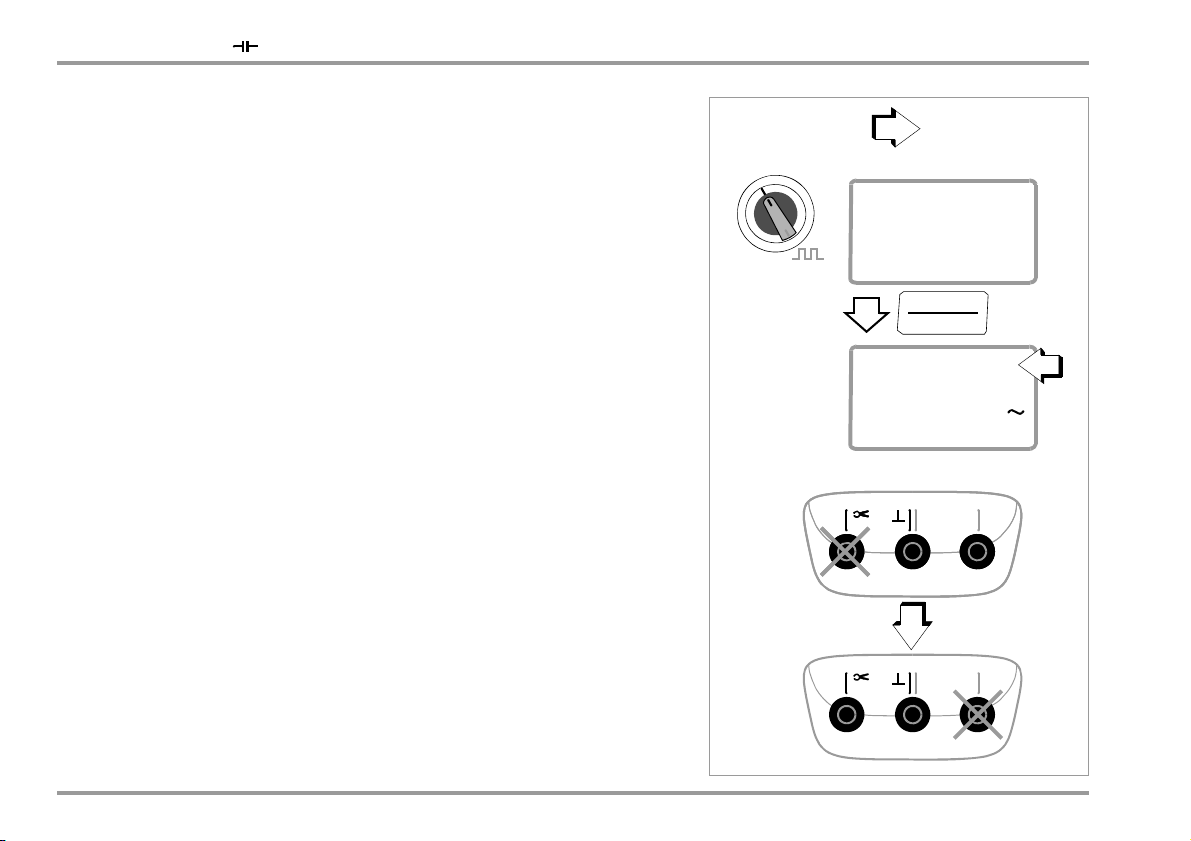
5.8.3 Direct Current Measurement with Current Clamp Sensor, mA DC
Voltage/Current Transformer Output
When a current clamp sensor is connected to the multimeter
( V input / mA input), all current displays appear with the
correct value in accordance with the selected transformation
ratio. The only prerequisite is that the current sensor is equipped
with at least one of the below listed transformation ratios, and that
the ratio has been previously selected in the following menu
(Cl ip 0FF) (see also section 7.4).
Current Clamp Setup Menu
... SET rAtE ... CLIP
1nFo
Z202A, Z203A,
WZ12C
CL
IP
Tra ns fo rme r
Ratios
1:1
1mV/1mA
1:10
1mV/10mA
1:100
1mV/100mA
1:1000
1 mV/1 A
1 / 10/100/1000 / 0ff
DMM Measuring Ranges Clamp Types
300 mV 3 V 30 V
300,00 mA 3,0000 A 30,000 A WZ12C
3,0000 A 30,000 A 300,00 A WZ12B, Z201A
30,000 A 300,00 A 3000,0 A Z202A
300,00 A 3000,0 A (3000,0 A)
The maximum allowable operating voltage is equal to the nominal
voltage of the current transformer.
When reading the measured
value, additional error resulting from the current clamp sensor must
also be taken into consideration.
(default setting: OFF)
40 GMC-I Messtechnik GmbH
Page 41

5.8.4 AC Measurement with Current Clamp Sensor, A AC and Hz
MEAS / CAL
SETUP
OUT
ENTER
OUT
ENTER
OUT
ENTER
003.50
A
A~
Hz
050.10
Hz
–+ +
~
R
x
Current
Ri = 1 M9 M
mA~
ZERO/SEL
ESC
AC
Voltage/Current Transformer Output
When a current clamp sensor is connected to the multimeter
( V input / mA input) all current displays appear with the correct value in accordance with the selected transformation ratio.
The only prerequisite is that the current sensor is equipped with at
least one of the below listed transformation ratios, and that the
ratio has been previously selected in the following menu
(Cl ip 0FF) (see also section 7.4).
Current Clamp Setup Menu
... SET rAtE ... CLIP
1nFo
V/Hz, , Temperature, and A/Hz Measurements
1 / 10/100/1000 / 0ff
Tra ns fo rma tion Ratios
CL IP
1:1
1mV/1mA
1:10
1mV/10mA
1:100
1mV/100mA
1:1000
1 mV/1 A
The maximum allowable operating voltage is equal to the nominal
voltage of the current transformer.
value, additional error resulting from the current clamp sensor must
also be taken into consideration.
GMC-I Messtechnik GmbH 41
DMM Measuring Ranges Clamp Types
300 mV 3 V 30 V
300,00 mA 3,0000 A 30,000 A WZ12C
3,0000 A 30,000 A 300,00 A WZ12B, Z201A
30,000 A 300,00 A 3000,0 A Z202A
300,00 A 3000,0 A (30000,0 A)
When reading the measured
(default setting: OFF)
Z202A, Z203A,
WZ12C
Page 42

V/Hz, , Temperature, and A/Hz Measurements
MEAS / CAL
SETUP
OUT
ENTER
OUT
ENTER
OUT
ENTER
003.50
A
A
DC
–+ +
~
R
x
Current
Ri 1
mA~
mA
003.50
A
A~
Hz
050.10
Hz
ZERO/SEL
ESC
AC
5.8.5 Direct and Alternating Current Measurement with Current Clamp
Transformer, mA DC, mA AC and Hz
Current/Current Transformer Output
When a current clamp transformer is connected to the multimeter
( mA input), all current displays appear with the correct value in
accordance with the selected transformation ratio. The only
prerequisite is that the current transformer is equipped with at
least one of the below listed transformation ratios, and that the
ratio has been previously selected in the following menu
(Cl ip 0FF) (see also section 7.4).
Current Clamp Setup Menu
... SET rAtE ... CLIP
1nFo
1 / 10/100/1000 / 0ff
CL IP
Tra ns fo rme r
Ratios
1:1
1mA/1mA
1:10
1mA/10mA
1:100
1mA/100mA
1:1000
1 mA/1 A
(default setting: OFF)
DMM Measuring Ranges Clamp Types
300 mV 3 V 30 V
300,00 mA 3,0000 A 30,000 A
3,0000 A 30,000 A 300,00 A
30,000 A 300,00 A 3000,0 A
300,00 A 3000,0 A (30000,0 A)
WZ12A, WZ12D,
WZ11A, Z3511,
Z3512, Z3514
42 GMC-I Messtechnik GmbH
Page 43

V/Hz, , Temperature, and A/Hz Measurements
GMC-I Messtechnik GmbH 43
Page 44

Calibration Functions: V – Hz – – Temp – mA – mA
0030.6
V
AC
0000.1
Hz
V~
V/Hz
MEAS/CAL
SETUP
V~
CALIBRATORMULTIMETER
Hz
0.000 calibV
Long
–+ +
–+ +
V; Hz, ; C;
mA
mA
6 Calibration Functions
6.1 Switching from the Measuring Function to the Calibration Function
If any measuring function is active, press and hold the
MEASURE / CAL | SETUP key in order to switch the calibration function.
The standby function is automatically activated during switchover.
44 GMC-I Messtechnik GmbH
Page 45

Calibration Functions: V – Hz – – Temp – mA – mA
–+ +
–
+
Input
Device to be Calibrated
e.g. Measuring Transducer
1k
V
ON/OFF
LIGHT
ZERO/ SEL
ESC
OUT
ENTER
OUT
ENTER
6.2 Voltage Source [V]
Voltages within the following ranges can be simulated:
0 60 mV, 0 300 mV, 0 3 V, 0 10 V and 0 15 V.
Resistance of the connected circuit should not be any less than
1k.
Selecting a Voltage Range for the Fixed Value Function
➭ Press the ZERO / SEL | ESC key in order to switch to the
[
select range] menu.
➭ Select the desired voltage range with the keys.
Acknowledge your selection with OUT | ENTER.
The display is switched to the voltage value entry window, but
the selected voltage range still appears in the auxiliary display.
Selecting the Voltage Range for the Interval or Ramp Function
➭ Press the ZERO / SEL | ESC key in order to switch to the
[
select range] menu. Select the desired voltage range with
the keys.
➭ Switch to the interval or ramp function menu with the
keys (see section 6.7). Start the respective function with
OUT | ENTER.
Abbreviated Instructions
➭ Select the V calibration function with the rotary switch.
Select calibration function.
➭ Switch the calibrator on by pressing the ON / OFF | LIGHT key.
The last selected voltage range is displayed.
➭ Connect the device to be calibrated with the measurement
cable as shown.
➭ Setting the voltage value:
Select voltage range and acknowledge for fixed value function.
ON indicates:
Voltage is applied directly to the output!
select range 15 V 60 mV
Select the digit to be changed with the keys, and change
the respectively selected digit with the keys.
➭ Connect the device to be calibrated with the measurement
cable as shown.
➭ The output can be activated with the OUT | ENTER key, or
deactivated [
Stdby] once again.
GMC-I Messtechnik GmbH 45
Change the fixed value.
000.00 V
(Negative values within a range of 60 mV or 300 mV can be selected by
scrolling with the
key to below the zero point.)
Activate output:
Page 46

Calibration Functions: V – Hz – – Temp – mA – mA
Note
Attention!
!
Hz
ON/OFF
LIGHT
ZERO/ SEL
ESC
ZERO/SEL
ESC
OUT
ENTER
ZERO/ SEL
ESC
OUT
ENTER
OUT
ENTER
6.3 Pulse, Frequency Generator (positive square-wave pulse) [Hz]
Voltage and frequency can be set independent of each other for
frequency generators.
The output signal is a square wave. Resistance of the connected
circuit should not be any less than 1 k.
➭ Select the /HZ calibration function with the rotary switch.
➭ Switch the calibrator on by pressing the ON / OFF | LIGHT key.
➭ Connect the device to be calibrated with the measurement
cable in the same way as specified for the voltage simulator.
➭ Set the voltage range (300 mV, 3 V, 10 V or 15 V):
Switch to the voltage range menu by pressing the
ZERO / SEL | ESC key twice [
voltage range with the keys. Acknowledge your selection
with OUT | ENTER. The display is switched to the voltage
amplitude entry window.
➭ Set voltage amplitude (0 15 V):
Select the digit to be changed with the keys, and change
the respectively selected digit with the keys. Acknowledge your selection with OUT | ENTER. The display is switched
to the frequency entry window, but the selected voltage amplitude still appears in the auxiliary display.
➭ Set frequency (1 2000 Hz):
ON indicates: Voltage is applied directly to the output using the selected frequency!
Select the digit to be changed with the keys, and change
the respectively selected digit with the keys.
➭ The output can be activated with the OUT | ENTER key, or
deactivated [
Stdby] once again.
select range]. Select the desired
The following error messages are possible: “HiCurr” (high
current – current at overload limit) where I
“0ut0l” and 3 acoustic signals (out of limit – limit value
.=18mA,
max
exceeded) where I > 27 mA; the simulator is switched off.
No external voltage may be applied to the calibrator jacks in this
operating mode. The calibrator is protected against brief
application of large external voltages with a replaceable fuse in the
event of operator error (see section 10.3).
Abbreviated Instructions
Select calibration function.
Set the voltage range (starting from frequency display).
select range 15 V 60 mV
Set voltage amplitude (starting from frequency display).
000.00 V
Set frequency.
0000.0 Hz
Activate output:
46 GMC-I Messtechnik GmbH
Page 47

Calibration Functions: V – Hz – – Temp – mA – mA
Note
–+ +
2-Wire Resistance Calibrator
Device to be Calibrated
–
+
Input
Measuring Current: 50 A ... 5 mA
ON/ OFF
LIGHT
OUT
ENTER
6.4 Resistance Simulation []
The resistance simulator is capable of simulating resistors using
2-wire connection for the following range: 5 2000 .
➭ Select the calibration function with the rotary switch.
➭ Switch the calibrator on by pressing the ON / OFF | LIGHT key.
➭ Connect the device to be calibrated with the measurement
cable as shown.
➭ Set the resistance simulation value:
ON indicates: The output is active!
Select the digit to be changed with the keys, and change
the respectively selected digit with the keys.
➭ The output can be activated with the OUT | ENTER key, or
deactivated [
Switching Between the Fixed Value, Interval and Ramp Functions
➭ Press the ZERO / SEL | ESC key in order to switch to the
[
select range] menu.
➭ Switch to the interval or ramp function menu with the
keys. Start the respective function with OUT | ENTER.
GMC-I Messtechnik GmbH 47
Stdby] once again.
Abbreviated Instructions
Select the calibration function.
Change the fixed value.
0000.0
Activate output:
The following error messages are possible: “HiCurr” (high
current – current value to high) where I > 4.5 mA and
“LoCurr” (low current – current too low or reversed polarity)
where I < 40 A (corresponds to unconnected sockets).
No external voltage may be applied to the calibrator jacks
in this operating mode.
The calibrator is protected against brief application of a
large external voltages with a replaceable fuse in the event
of operator error (see section 10.3).
Response time of the calibrator output to the specified resistance
value after measuring current is applied is max. 30 ms. Devices
under test with non-continuous measuring current (e.g. scanned
measuring inputs) result in erroneous measured values, if
measurement is started before response time has elapsed. The
calibrator cannot be used for devices of this type.
Page 48

Calibration Functions: V – Hz – – Temp – mA – mA
MEAS/ CAL
SETUP
OUT
ENTER
OUT
ENTER
OUT
ENTER
MEAS/ CAL
SETUP
MEAS/ CAL
SETUP
OUT
ENTER
OUT
ENTER
OUT
ENTER
OUT
ENTER
MEAS/ CAL
SETUP
MEAS/ CAL
SETUP
OUT
ENTER
OUT
ENTER
OUT
ENTER
OUT
ENTER
OUT
ENTER
MEAS/ CAL
SETUP
6.5 Temperature Simulation [°C / °F]
The temperature simulator is capable of simulating resistance
temperature detectors (RTD) or thermocouples (TC) with
specification of the external reference junction temperature.
➭ Select the Temp RTD or Temp TC calibration function with the
rotary switch.
➭ Switch the calibrator on by pressing the ON / OFF | LIGHT key.
The last selected temperature sensor is displayed.
➭ Connect the device to be calibrated with the measurement
cables.
➭ Set the temperature value:
Simulated resistance or simulated voltage is applied directly to the
output!
Select the digit to be changed with the keys, and change
the respectively selected digit with the keys. As an
alternative, press and hold the keys with the cursor at
any entry position until the higher value digits are scrolled
through as well.
➭ The output can be activated with the OUT | ENTER key, or
deactivated [
Stdby] once again.
Selecting Resistance Temperature Detector (RTD) or Thermocouple (TC)
for Fixed Value, Interval or Ramp Function
➭ Switch to the fixed value, interval or ramp function menu by
pressing the ZERO / SEL | ESC key.
➭ Select the [
select sensor] menu with the keys.
➭ Select the desired sensor with the keys. Acknowledge
your selection with OUT | ENTER. The display is switched to the
window for temperature value entry, but the selected
sensor still appears in the auxiliary display.
The reference temperature is indicated in the auxiliary display.
Parameter Entries for Thermocouple Temperature Simulation
Select unit of measure °C or °F – SEt menu.
info set
time ...tempintern
unitset °F °C
Select internal reference temperature – SEt menu.
info set time ...tempextern
unitset temp set extern intern
temp intern23.7 °C
Select and set external reference temperature – SEt menu.
info set
time ...tempintern
unitset temp set intern extern
externset 21.0 °C
tempextern 22.4 °C
48 GMC-I Messtechnik GmbH
Page 49

Calibration Functions: V – Hz – – Temp – mA – mA
RTD
ON/ OFF
LIGHT
ZERO/ SEL
ESC
OUT
ENTER
OUT
ENTER
TC
ON/ OFF
LIGHT
ZERO/ SEL
ESC
OUT
ENTER
6.5.1 Temperature Simulation for Resistance Thermometers – RTD Temperature Setting
Resistance temperature detectors (types Pt100, Pt1000, Ni100
and Ni1000) are simulated by means of resistance values.
Abbreviated Instructions
Select calibration function.
Select sensor value and acknowledge for fixed value function.
select sensor Pt100 ...ni1000
Set temperature simulator value.
120.0 °C
Activate output:
Response time of the calibrator output to the specified resistance
value after measuring current is applied is max. 30 ms.
Devices under test with non-continuous measuring current (e.g.
scanned measuring inputs) result in erroneous measured values,
if measurement is started before response time has elapsed. The
calibrator cannot be used for devices of this type.
6.5.2 Temperature Simulation for Thermocouples – TC Temperature Setting
Thermocouples (types B, E, J, K, L, N, R, S, T and U) are
simulated with voltage. Internal or external temperature
compensation is possible.
Abbreviated Instructions
Select calibration function.
Select sensor value and acknowledge for fixed value function.
select sensor b ...u
Set temperature simulator value.
120.0 °C
Select internal or external reference temperature,
set external reference temperature (see page 48).
GMC-I Messtechnik GmbH 49
Page 50

Calibration Functions: V – Hz – – Temp – mA – mA
–+ +
–+ +
Device to be
Terminal Block
Equalizing Leads
Device to be
Copper Wire
Temperature
measurement,
e.g. using multimeter with temperature sensor
Example for a)
Internal Ref. Junction
Example for b)
External Ref. Junction
calibrated
calibrated
Function Description and Applications
10 different types of thermocouples can be selected, and can be
simulated within the temperature ranges specified by IEC/DIN.
Selection can be made between an internally measured reference
junction temperature, or numeric entry of an external reference
junction temperature within a range of -30 to +60 C.
Important Notes Regarding Reference Temperature
Internal reference temperature is continuously measured with an
integrated temperature sensor.
The reference temperature is generally measured at the
thermocouple connector jack for devices to be calibrated with a
thermocouple measuring input.
The two measurements may yield different results, and
differences are registered as errors during thermocouple
simulation. The following methods help to reduce this error:
a) The device to be calibrated is connected to the jacks at the
calibrator with equalizing leads for the thermocouple to be
simulated.
b) The temperature of the thermocouple connector jack at the
device to be calibrated is measured with a precision
temperature measuring instrument, and the resulting value is
entered to the calibrator as a reference temperature. The
calibrator and the device to be calibrated are connected with
copper wire.
Otherwise, the external reference temperature is entered in all
cases where temperature measurement at the device to be
calibrated is accomplished by means of a thermostatic reference
junction (end of the thermocouple equalizing lead).
No external voltage may be applied to the calibrator jacks
in this operating mode.
The calibrator is protected against brief application of large
external voltages with a replaceable fuse in the event of
operator error (see section 10.3).
50 GMC-I Messtechnik GmbH
Page 51

Calibration Functions: V – Hz – – Temp – mA – mA
mA
ON/ OFF
LIGHT
ZERO/ SEL
ESC
OUT
ENTER
OUT
ENTER
6.6 Current Source and Current Sink [mA]
➭ Select the mA current sink ( ) or mA current source ( )
calibration function with the rotary switch.
➭ Switch the calibrator on by pressing the ON / OFF | LIGHT key.
The last selected current range is displayed.
➭ Connect the device to be calibrated with the measurement
cables (see example in section 6.6.1).
➭ Set the current simulation value:
SINK ON indicates that the current sink is active!
SOURCE ON indicates that the current source is active!
Select the digit to be changed with the keys, and change
the respectively selected digit with the keys.
➭ The current sink / current source can be deactivated by
pressing the OUT | ENTER key [SINK/SOURCE
Stdby], or activated
once again.
Selecting a Current Range for the Fixed Value Function
➭ Press the ZERO / SEL | ESC key in order to switch to the
[select range] menu.
➭ Select the desired current range with the keys (0
20 mA, 4 20 mA or 0 24 mA).
Acknowledge your selection with OUT | ENTER.
The display is switched to the current value entry window, but
the selected current range still appears in the auxiliary display.
Selecting the Current Range for the Interval or Ramp Function
➭ Press the ZERO / SEL | ESC key in order to switch to the
[
select range] menu. Select the desired current range with the
keys.
➭ Switch to the interval or ramp function menu with the
keys. Start the respective function with OUT | ENTER.
Abbreviated Instructions
Select the calibration function.
Select current range and acknowledge for fixed value function.
select range 0 20 0 24 4 20
Change the fixed value.
15.00 mA
Activate output:
% read-out (relationship of setting value to simulator’s upper range limit)
The display is switched from mA to % by pressing and holding the
OUT | ENTER key.
GMC-I Messtechnik GmbH 51
Page 52

Calibration Functions: V – Hz – – Temp – mA – mA
Note
Note
–+ +
Periphery Devices
24 V
4 ... 20 mA = 0 ... 100 C
+
+
–
–
Power
Supply
–+ +
Periphery Devices
+
–
6.6.1 Current Sink – Simulation of a 2-Wire Transmitter
A current sink (0 24 mA) or current loop load can be simulated
with this function. The calibrator regulates the current, which flows
via the calibrator jacks from an external power supply,
independent of direct voltage applied to the jacks (4 26 V). The
calibrator varies internal resistance such that the selected current
value is maintained.
The last selected simulation range is saved to memory.
Voltage at the calibrator jacks may not exceed 26 V in the
current sink operating mode, because thermal overload
would otherwise occur and the fuse would blow.
LoVolt appears at the display if voltage is too low.
Example of a 2-Wire Transmitter Measuring Circuit
6.6.2 Current Source
Internal supply power is used to simulate a current source.
The current source’s internal control loop is monitored: If
voltage drop at the external load (burden) is greater than
20 V, or if the electrical circuit is interrupted, “Hi burd”
appears at the display.
No external voltage may be applied to the calibrator jacks
in this operating mode.
The calibrator is protected against brief application of large
external voltages with a replaceable fuse in the event of
operator error (see section 10.3).
52 GMC-I Messtechnik GmbH
Page 53

Calibration Functions: V – Hz – – Temp – mA – mA
Auto
Final Value
Initial Value
Initial Value
Final Value
manual
6.7 Interval Functions, Ramp Functions
Two types of setpoint sequences can be generated in order to
simulate sensor conditions at the inputs of transducers,
transmitters and buffer amplifiers:
• Interval sequences (see section 6.7.1)
automatic (periodic) or manually controlled sequences
or
• Ramp sequences (see section 6.7.2)
endless loops (periodic) or one-time only sequences
The above mentioned sequences can be conveniently generated
at a PC with the help of METRAwin
90-2 software as an
accessory.
6.7.1 Interval Sequences – INT Function
Output ranges are divided into rising or falling interval steps with
this function, and the number of interval steps, as well as their
duration, can be specified. This function is above all suitable for
calibrating analog displays and recorders during one-man
operation.
Input parameters for interval sequences:
• All simulation functions except for Hz can be adjusted as
output quantities.
•A lower (
Start) and an upper (End) range limit can be selected
for each output quantity from within the overall range.
• The number of steps can be set within a range of 1 99.9.
The number of steps can be entered as a whole number as
well, which is especially practical for analog indicators and
recorders with non-standardized scale divisions.
• The interval duration per step (t1) can be selected from within
a range of 1 second to60 minutes.
• Step jumps can be executed manually (
the and keys, or automatically (
selectable time per step.
Examples of Automatic Interval Sequences
Examples of Manual Interval Sequences
1nt mode = manual) with
1nt mode = Auto) with
GMC-I Messtechnik GmbH 53
Page 54

Calibration Functions: V – Hz – – Temp – mA – mA
ZERO/ SEL
ESC
MEAS/ CAL
SETUP
OUT
ENTER
OUT
ENTER
OUT
ENTER
OUT
ENTER
OUT
ENTER
OUT
ENTER
4
8
12
16
20
t[s]
I
Source
Manual Stop
[mA]
➀➂
ESC
➁
The time intervals depend on the operator
(they’re only identical in the automatic mode).
OUT
ENTER
ZERO/SEL
ESC
Setting the Interval Parameters
seleCt range 300 mV 15 V 1nt
Initial value:
Final value:
1nt start 02.000 V
1nt end 10.000 V
Example of a Manually Controlled Interval Sequence
Steps: 1nt steps 03.0
Dwell time:
Repetition:
(Auto = automatic sequence, MAnuAL = manual sequence)
1nt t1 00.05 min.s
1nt mode auto manual
Key
Manually Controlled Interval Sequence
After entering all parameters for the “manual interval sequence”
output function (
the
key, the individual steps are triggered with the and keys.
The relationship between the output signal and each of the key
operations is depicted with the help of the following example.
54 GMC-I Messtechnik GmbH
1nt mode = manual) and starting the function with
1 When 1nt
Start the sequence by pressing
2 The sequence is continued in the corresponding direction by
pressing the or key.
3 Stop the interval sequence by pressing the key.
ready appears at the display
Page 55

Calibration Functions: V – Hz – – Temp – mA – mA
2
4.6
7.3
10
t[s]
U
[V]
run up stop
➀➃➁
5101520250
➂
run dn hold run up run dn
HOLD CONT
LCD :
ESC/
OUT
ENTER
ZERO/SEL
ESC
Automatic Interval Sequence
Automatic execution of a programmed sequence range is above
all advisable if feed to the signal circuit and scanning of the
peripheral device under test are physically separated.
After entering all parameters for the “automatic interval sequence”
output function (see above) (I
be started and stopped whenever desired, as well as resumed.
GMC-I Messtechnik GmbH 55
nt, mode = auto), the sequence can
Example of an Automatic Interval Sequence
Interval parameters: output quantity: U (range of 0 15 V),
start =2V, end = 10 V, number of interval steps = 3, t1 =5s,
mode = auto
Key
1 When 1nt
ready appears at the display:
Start the sequence by pressing
2 The sequence is stopped by pressing the or the key.
Interval time elapsed thus far is saved as tx.
3 The sequence is resumed by pressing the key, and
remaining sequence duration t
=t1–tx.
y
4 Stop the interval sequence by pressing the key.
Page 56

Calibration Functions: V – Hz – – Temp – mA – mA
3,0,0 (t1, t2, t3)
1,0,4
0,2,0
0,1,2
0,0,3 (t1, t2, t3)
2,0,2
2,1,0
2,1,2
6.7.2 Read-Out a Periodic Ramp – RAMP Function
Ramp-type signals can be used to test the dynamic performance
of devices to be calibrated, or entire measuring circuits. An
example would be performance of a control loop with a setpoint
specified via the analog setpoint input at the controller. The
instrument can be used to replace costly hardware and software
for the set-up of long-term test bays with cyclical time sequences.
Parameters for the ramps are depicted below:
• The following functions can be adjusted as output quantities:
voltage U, current sink I Sink, current source I Source,
resistance R or temperature temp (TC or RTD).
•A lower (
Start) and an upper (End) range limit can be selected
for each output quantity from within the overall range.
• Rise time t1 and fall time t3 are adjustable from
0 seconds 60 minutes.
• Dwell time t2 at the upper and lower range limits is adjustable
from 0 seconds 60 minutes.
• There are 2 ramp sequences:
– One-time only (
– Repetition (
onCE): t1, t2, t3
repeat): t1, t2, t3, t2, t1, t2, t3,
Examples of Ramp Sequences
56 GMC-I Messtechnik GmbH
Page 57

Calibration Functions: V – Hz – – Temp – mA – mA
ZERO/ SEL
ESC
MEAS/ CAL
SETUP
OUT
ENTER
OUT
ENTER
OUT
ENTER
OUT
ENTER
OUT
ENTER
OUT
ENTER
Start
End
t1
t2
t3
t2
Output
t
OUT
ENTER
Setting Ramp Parameters
seleCt range 300 mV 15 V ramp
Initial value:
Final value:
Rise time:
ramp start 02.000 V
ramp end 10.000 V
ramp t1 00.05 min.s
Dwell time: ramp t2 00.08 min.s
Fall time:
Repetition:
(rEPEAT = endless loop, onCE = one-time only)
ramp t3 00.05 min.s
ramp mode repeat onCe
Example of a Periodic Ramp Sequence
The relationship between the output signal and each of the key
operations is depicted with the help of the following example.
Manually Controlled Ramp Sequence
After entering all parameters, start with .
Rising or falling ramps can be triggered with the or key.
GMC-I Messtechnik GmbH 57
Page 58

Calibration Functions: V – Hz – – Temp – mA – mA
2V
10 V
t1 t2 t3
LCD :
t3 t2
t1
➀➁➂➃➄➅
t1 up t2 run t3 dn t3 hld t3 up t3 run t3 hld t1 dn
U
[V]
HOLD CONT
HOLD CONT
/
/
ESC
OUT
ENTER
ZERO/ SEL
ESC
Example of a Periodic Ramp Sequence Controlled by Manual Intervention
6.7.3 Dual Mode (simultaneous simulation and measurement)
All simulation functions can be activated and, at the same time,
transmitter signal U or I can be measured in the most commonly
used measuring ranges (30 V DC or 30 mA DC) in the dual
operating mode.
Special case: simulation and measurement of voltage or current
without an external circuit. For example, if voltage output needs to
be tested, you only need to connect the Calibrator+ and Sense+
sockets to each other, because the Calibrator– and Sense– jacks
are connected internally.
Activating the Dual Mode
➭ Select a simulator function with the rotary switch. The calibra-
tion operating mode must be activated (see section 6.1).
➭ Press and hold the ZERO / SEL | ESC key for approximately 2
Ramp parameters: output quantity: U (range of 0 15 V),
start =2V, end =10V, t1 =5s, t2 =8s, t3 =5s,
for periodic ramp
repeat
Key
1 When ramp
Start the sequence by pressing
2 Stop the falling ramp within fall time t3 with the or the
key.
ready appears at the display:
3 Start a rising ramp within remaining fall time t3 with the key.
4 Stop the ramp sequence by pressing the or the key.
5 Start a falling ramp with the key, remaining dwell time t2 is
cleared.
6 Stop the ramp sequence by pressing .
58 GMC-I Messtechnik GmbH
seconds, and select the U
keys.
➭ Press the OUT | ENTER key in order to acknowledge your
selection.
➭ Depending upon the calibration function, select either the
simulator range or the sensor with the ZERO / SEL | ESC key.
➭ Set the simulation value in the main display with the
➭ Activate the output by pressing the OUT | ENTER key.
The respective measured values appear in the left-hand auxiliary
display, and DUAL appears to the right of the measured values.
➭ Exit the “dual mode” function by turning the rotary switch, or
by pressing and holding the ZERO / SEL | ESC key for
approximately 2 seconds, selecting OFF in the menu with the
keys and acknowledging with OUT | ENTER.
or Idc measuring function with the
dc
keys.
Page 59

Calibration Functions: V – Hz – – Temp – mA – mA
0FF
Acknowledge
ZERO/SEL
ESC
SET
DUAL
Long
1dc 30Vdc 30
0ff
mAV
02.000
00.340
DUAL
OUT
ENTER
OUT
ENTER
Acknowledge
mA
Te mp
V
Hz
Deactivate Dual Mode
0FF
ZERO/ SEL
ESC
SET
DUAL
Long
or
V mA
Select Range
select range / select sensor
Change Value
000.00
ZERO/SEL
ESC
OUT
ENTER
–+ +
mA
T
GMC-I Messtechnik GmbH 59
Page 60

Device and Measuring Parameters
MEAS / CAL
SETUP
OUT
ENTER
OUT
ENTER
OUT
ENTER
OUT
ENTER
7 Device and Measuring Parameters
The instrument’s “SET” mode (menu mode) makes it possible to
set operating and measuring parameters, query information and
activate the interface.
➭ The menu mode is accessed by pressing the
MEAS / CAL | SETUP key, assuming that the instrument is
switched on and set to “Measure” (measuring mode).
“1nFo” appears at the display.
➭ The main menus, i.e. the “SETUP”, “ tEMP” “SEnd” and “StorE”
menus, are accessed, and the display is once again returned to
“InFo”, by activating the
➭ After selecting the desired main menu, sub-menus are
accessed by pressing the OUT | ENTER key.
➭ The desired parameter is selected by repeatedly pressing the
key.
➭ In order to check or change a parameter, acknowledge it with
the OUT | ENTER key.
➭ The
keys can be used to position the cursor at the entry
position. The desired value is selected with the help of the
keys.
➭ Changes can only be accepted with the OUT | ENTER key.
➭ You can return to the sub-menu without making any changes
by pressing the ZERO / SEL | ESC key, and to the main menu by
pressing the ZERO / SEL | ESC key once again etc.
➭ You can switch to the measuring mode from any menu level by
pressing the OUT | ENTER key.
keys (in any direction).
After repeatedly pressing the MEAS / CAL | SETUP key (without first
turning the multimeter off), you can return to the last selected
menu or parameter from the measuring mode.
Example: Setting Time
1nFo ... set rAte ... t iME
10:24 (hh:mm)
Setting hours and minutes:
Change the setting, the entry position blinks.
Advance to desired entry position.
Press and hold the key
to change the setting rapidly.
The new time setting is activated after
acknowledgment.
60 GMC-I Messtechnik GmbH
Page 61

Device and Measuring Parameters
bAtt:
0CCvP:
dAtE:/
t iME:
caldat
:
1tEMP:
1nFo
SEnd SET StorE
StArt
StoP
000.0
CLEAr
StArt/
StoP
Sub-Menus/Parameters
tempext
tempunit
beep
rAtE
APoFF
bEEP
irStb
Addr
dAtE
tiME
Main Menus
Query Set Set Set
OUT
ENTER
OUT
ENTER
OUT
ENTER
OUT
ENTER
1nfo
MEAS / CAL
SETUP
020.00
V
DC
AC
TRMS
Acknowledge
OUT
ENTER
Acknowledge
OUT
ENTER
Acknowledge
OUT
ENTER
7.1 Paths to the Various Parameters 7.2 List of All Parameters
GMC-I Messtechnik GmbH 61
Parameter
0.diSP
Addr
APoFF
bAtt
bEEP
caldat
CLEAr
CLAMP
dAtE
EMpty
1nfo
irStb
1tEMP
0CCvP
rAtE
SEnd
SET
StArt
StoP
store
tEMP
t iME
Page: Header
62: 0.diSP – show/hide leading zeros
67: Configuring Interface Parameters
63: APoFF – specified time for automatic shutdown and continuous ON
62: bAtt – query battery voltage
63: bEEP – set limit value for continuity testing
62: cALdAt – query calibration date
23: Measurement Data Recording
40: Direct Current Measurement with Current Clamp Sensor, mA DC
41: AC Measurement with Current Clamp Sensor, A AC and Hz
42: Direct and Alternating Current Measurement with Current Clamp Transformer, mA DC, mA AC and Hz
62: query date and time
enter date
64: dAtE –
23: Measurement Data Recording
62: Querying Parameters – InFo Menu (as moving letters)
67: Configuring Interface Parameters
62: ItEMP – query reference temperature
23: Measurement Data Recording
62: rAtE
–
set the sampling rate
66: Activating the Interface
62: Entering Parameters – SETUP Menu
23: Measurement Data Recording
33: Temperature Measurement
62: querying date and time,
64: tiME
– set time
Page 62

Device and Measuring Parameters
MEAS / CAL
SETUP
OUT
ENTER
MEAS / CAL
SETUP
OUT
ENTER
MEAS / CAL
SETUP
OUT
ENTER
MEAS / CAL
SETUP
OUT
ENTER
MEAS / CAL
SETUP
OUT
ENTER
MEAS / CAL
SETUP
OUT
ENTER
OUT
ENTER
OUT
ENTER
MEAS / CAL
SETUP
OUT
ENTER
OUT
ENTER
OUT
ENTER
7.3 Querying Parameters – InFo Menu (as moving letters)
bAtt – query battery voltage
1nFo bAtt: 3.1 V.
OCCUP – query memory occupancy
1nFo
bAtt:
...
0CCvP: 000.0
%
querying date and time
1nFo bAtt:
13:46:56 (hh:mm:ss)
t iME:
D = day, M = month, Y = year, h = hour, m = minute, s = second
... 31.12.
2009 (DD.MM.YYYY)
Date and time must be reentered after replacing the batteries.
cALdAt – query calibration date
1nFo bAtt:
caldat: 06.07.09 ver2.00
ItEMP – query reference temperature
The temperature of the internal reference junction is measured with a
temperature sensor in close proximity to the input sockets.
1nFo bAtt: ...
1tEMP: 24
°C
7.4 Entering Parameters – SETUP Menu
rAtE – set the sampling rate
The sampling rate specifies the time interval after which the
respective measured value is transmitted to the interface, or to
measured value memory.
Any one of the following sampling rates can be selected:
[mm:ss.t] 00:00.1, 00:00.2, 00:00.5, 00:01.0, 00:02.0, 00:05.0
[h:mm:ss.z] (h=hours, m=minutes, s=seconds
, z=tenths of a sec.
0:00:10, 0:00:20, 0:00:30, 0:00:40, 0:00:50, 0:01:00, 0:02:00,
0:05:00, 0:10:00, 0:20:00, 0:30:00, 0:40:00, 0:50:00, 1:00:00,
2:00:00, 3:00:00, 4:00:00, 5:00:00, 6:00:00, 7:00:00, 8:00:00,
9:00:00
Setting the Sampling Rate
1nFo
...
SET time ... rAtE
00:00.1 ... 00:00.5 ... 9:00:00
(00:00.5 = 0.5 s = default value)
0.diSP – show/hide leading zeros
This parameter determines whether or not leading zeros will
appear in the measured value display.
1nFo
...
SET time ... 0.diSP
)
0000.0 : with leading zeros (default value)
0.0 : leading zeros suppressed
62 GMC-I Messtechnik GmbH
Page 63

Device and Measuring Parameters
MEAS / CAL
SETUP
OUT
ENTER
OUT
ENTER
OUT
ENTER
MEAS / CAL
SETUP
OUT
ENTER
OUT
ENTER
OUT
ENTER
APoFF – specified time for automatic shutdown and continuous ON
DMM
The instrument is switched off automatically if the measured value
remains unchanged for a long period of time, and if none of the
keys or the rotary switch have been activated before the specified
time “APoFF” (entered in minutes) has elapsed.
Calibrator
The instrument switches the output off automatically if none of the
keys or the rotary switch have been activated during the time
specified in minutes in “APoFF”. The display is also switched off
after one additional minute.
Setting APoFF
If the on setting is selected, the multimeter is set to continuous
operation and
ON appears in the display to the right of the battery
symbol. In this case, the multimeter can only be switched off
manually. The “on” setting can only be canceled by changing the
respective parameter, and not by switching the instrument off.
... SET time ... APoFF
1nFo
10 ... 59 min on
(10 minutes = default setting)
bEEP – set limit value for continuity testing
1nFo
... SET time ... bEEP
1, 10, 20, 30, 40 ... 300
(10 = default setting)
irStb – status of infrared receiver in the stand-by mode
See section 8.2 on page 67 regarding settings.
Addr – set device address
See section 8.2 on page 67.
GMC-I Messtechnik GmbH 63
Page 64

Device and Measuring Parameters
MEAS / CAL
SETUP
OUT
ENTER
OUT
ENTER
OUT
ENTER
MEAS / CAL
SETUP
OUT
ENTER
OUT
ENTER
OUT
ENTER
OUT
ENTER
ZERO / SEL
ESC
ON / OFF
LIGHT
tiME – set time
Entering the correct time makes it possible to acquire measured
values in real-time.
... SET time ... t iME
1nFo
10:24:30 (hh:mm:ss)
Date and time must be reentered after replacing the batteries.
dAtE – enter date
Entering the current date makes it possible to acquire measured
values in real-time.
1nFo ... SET time ... dAtE
31.12 (DD: day . MM: month)
2005 (YYYY: year)
Date and time must be reentered after replacing the batteries.
7.5 Default Settings
Previously entered changes can be undone, and the default
settings can be reactivated. This may be advisable under the
following circumstances:
• After the occurrence of software or hardware errors
• If you are under the impression that the multimeter does not
work correctly
➭ Disconnect the device from the measuring circuit.
➭ Remove the batteries temporarily (see also section 10.2).
➭ Simultaneously press and hold the and
keys, and connect the battery at the same time.
64 GMC-I Messtechnik GmbH
Page 65

Device and Measuring Parameters
GMC-I Messtechnik GmbH 65
Page 66

Interface Operation
MEAS/ CAL
SETUP
OUT
ENTER
OUT
ENTER
MEAS/ CAL
SETUP
OUT
ENTER
OUT
ENTER
OUT
ENTER
8 Interface Operation
The METRACAL MC is equipped with an infrared interface for communication with the PC. Commands are optically transferred
through the instrument housing by means of infrared light to an interface adapter (accessory: USB X-TRA), which is plugged onto the
METRACAL MC. The adapter’s USB interface allows connection to
the PC via an interface cable.
Commands and parameters can be transmitted from the PC to the
METRACAL MC. The following functions can be executed:
DMM
• Configuration and read-out of measuring parameters
• Measuring function and measuring range selection
• Start measurement
• Read out stored measured values
Calibrator
• Configuration and read-out of calibration parameters
• Calibration function and measuring range selection
• Start calibration
• Programming of user-specific procedures (interval and ramp
functions)
8.1 Activating the Interface
The interface is automatically activated for receiving operation
(METRACAL MC receives data from the PC) as soon as the interface
is addressed by the PC, assuming that the “irStb” parameter
has been set to “on” (see section 8.2), or the instrument is already
switched on (the first command wakes up the METRACAL MC, but
does not yet execute any further commands).
The “continuous transmission” operating mode is selected
manually as described below. In this operating mode, the
instrument continuously transmits measurement data to the PC
via the interface adapter, which can then be displayed with the
help of a terminal program.
Starting Continuous Transmission Operation with Menu Functions
... SEnd StArt send
1nFo
The symbol blinks at the display indicating interface operation.
Stopping Continuous Transmission Operation with Menu Functions
1nFo ... SEnd send
stop send
The symbol is cleared from the display.
Automatic Activation and Deactivation of Transmission Mode Operation
If the sampling rate is 10 seconds or longer, the display is
switched off automatically between samples in order to prolong
battery service life. The only exception is when the multimeter is
set to continuous operation. As soon as an event occurs, the display is automatically switched back on.
66 GMC-I Messtechnik GmbH
Page 67

Interface Operation
MEAS/ CAL
SETUP
OUT
ENTER
OUT
ENTER
OUT
ENTER
MEAS/ CAL
SETUP
OUT
ENTER
OUT
ENTER
OUT
ENTER
8.2 Configuring Interface Parameters
1rStb – Status of the Infrared Receiver in the Stand-by Mode
There are two possible switching statuses for the infrared
interface when the multimeter is switched off:
ir on: IR appears at the display and the infrared interface is
active, i.e. signals such as making commands can be
received, and power is consumed even though the
multimeter is switched off.
ir oFF: IR does not appear at the display and the infrared
interface is switched off, signals cannot be received.
... SET time ... irStb
1nFo
ir on / ir oFF
(irstb = ir oFF = default setting)
Addr – Address
If several multimeters are connected to the PC via an interface
adapter, a separate address can be assigned to each instrument.
Address number 1 should be selected for the first instrument, 2
should be assigned to the second and so forth.
1nFo
... SET time ... Addr
00 ... 01 ... 15
(15 = default setting)
GMC-I Messtechnik GmbH 67
Page 68

Technical Data
9 Technical Data
Calibrator Section
Simulation
Range
Calibration
Function
Direct Voltage Source Minimum Load
Resolution
30,000 Digits
(4¾ places)
Resistance
060 mV 1 μV
Intrinsic
Uncertainty
±(% S + mV) I
0.1 + 0.01
0300 mV 0.01 mV 0.05 + 0.02
V
0 3 V 0.1 mV 0.05 + 0.2
1k
0 10 V 1 mV 0.05 + 2
0 15 V 1 mV 0.05 + 2
Pulse / Frequency Generator
Duty cycle (pulse-no-pulse ratio):
50%, Amplitude: 10 mV15 V
Minimum Load
Resistance
(% S + Hz) I
Hz 1 Hz 2 kHz 0,1 1 Hz 1 k 0.05 + 0.2 18 mA
Current Source Max. load (% S + A)
4 20 mA
mA
1 A 16 V 0.05 + 20 20 mA
0 24 mA
Current Sink (% S + A) U
4 20 mA
mA
1 AVin = 4 ... 26 V 0.05 + 2 26 V0 20 mA
0 24 mA
Resistance Simulation
52000 0.1 0.05...0.1..4...5 0.05 + 0.2 5 mA
1)
The selection of frequencies as of 29 Hz is only possible within a limited raster.
Sensor Current [mA]
(% S + )I
Overload
18 mA
max
max
max
max
Simulator for Temperature Sensors (resolution: 0.1 K)
Sensor Type Simulation
Range
in C
Resistance Thermometer per IEC 751 (% S + K) I
Pt100 –200 + 850 – 328+1562 0.1 + 0.5
Pt1000 –200 + 300 –328 +572 0.1 + 0.2
Resistance Thermometer per DIN 43760 (% S + K) I
Ni100 – 60 + 180 – 76 +356 0.1 + 0.5
Ni1000 – 60 +180 –76 + 356 0.1 + 0.2
RTD sensor current, 0.05 ... 0.1 ... 4
Thermocouples per DIN and IEC 584-1 U in mV
K (NiCr/Ni) –250+ 1372 –418+2501
C / F
J (Fe/CuNi) –210+1200 –346+2192
T (Cu/CuNi) –270+400 –454+ 752
B (Pt30Rh/Pt6Rh) +500+1820 +932+ 3308
E (NiCr/CuNi) –270+1000 –454+ 1832
R (Pt13Rh/Pt) –50+ 1768 –58+ 3214
N (NiCrSi-NiSi) –270+ 1300 –454+ 2372
S (Pt10Rh/Pt) –50+ 1768 –58+ 3214
J (Fe/CuNi) –200+ 900 – 328+ 1652
U (Cu/CuNi) –200+600 –328+ 1112
2)
Without internal reference junction, relative to fixed external reference temperature
and thermovoltage of the thermocouple, internal reference junction: intrinsic error
of 2 K, external reference junction: entry of –30 60 C
Simulation
Range
in F
... 5 mA
Intrinsic
Uncertainty
(0.05%
|Setting|
+
0.02)
Overload
max
5 mA
max
5 mA
2)
I
max
18 mA
Key
S = setting value
68 GMC-I Messtechnik GmbH
Page 69

Technical Data
Multimeter Section
Resolution at Upper
Meas.
Function
1)
2)
GMC-I Messtechnik GmbH 69
Measuring Range
4)
60mV
300 mV 10 V>20M 5M // < 50 pF 0.08 + 10
V
mA
F
Display: 3¾ places for capacitance measurement; a different resolution and
sampling rate can be selected in the rAtE menu for saving and transmitting
measured values.
20 45 65 Hz 1 kHz sine, for alternating voltage TRMSAC, measured values
< 100 digits are suppressed, see page 71 for influences
3V 100V11M 5M // < 50 pF 0.05 + 10 0.2 + 30 (> 100 d)
30 V 1 mV 10 M 5M // < 50 pF 0.05 + 10 0.2 + 30 (> 100 d)
300 V 10 mV 10 M 5M // < 50 pF 0.05 + 10 0.2 + 30 (> 100 d)
300 μA 10 nA 160 mV 160 mV 0.1 + 15 0.8 + 30 (> 100 d)
3 mA 100 nA 160 mV 160 mV 0.05 + 15 0.5 + 30 (> 100 d)
30 mA 1 A 180 mV 180 mV 0.05 + 15 0.5 + 30 (> 100 d)
300 mA 10 A 380 mV 380 mV 0.05 + 15 0.5 + 30 (> 100 d)
300 10 m 0.6 V 2 50 A0.1+5
3k 0.1 0.6 V 150 A0.1+5
30 k 1 0.6 V 30 A0.1+5
300 k 10 0.6 V 3 A0.2+5
3M 100 0.6 V 360 nA 0.5 + 10
30 M 1 0.6 V 100 nA 2 + 10
300 0.1 3V 1mA 2+5
6 V 1 mV 7 V Approx. 1 mA 0.5 + 3
30 nF 10 pF 1 M 3 V 1 + 10
300 nF 100 pF 100 k 3 V 1 + 6
3 F1nF1k 3 V 1 + 6
30 F10nF1k 3 V 1 + 6
300 F100nF3k 3V 5 + 6
Range Limit
1)
30000
(60000)
1 V>20M — 0.1 + 10
3100
1)
Open-circuit voltage
Discharge resistance U
Input Impedance
DC AC
Voltage drop at approx. range limit
DC AC
Measuring current at
2)
2)
range limit
0 max
3)
4)
5)
At 0 ... + 40 C
Only manually adjustable
ZERO is displayed for active “zero balancing” function,
maximum correction: 50% rdg.
Intrinsic Uncertainty at Highest Resolution
under Reference Conditions
(...% rdg. + ... d) (...% rdg. + ... d)
DC AC
5)
5)
DC AC
(...% rdg. + ... d)
5)
5)
10)
10)
(...% rdg. + ... d)
5) 10)
5) 10)
10)
10)
10)
2) 10
—
0.5 + 30 (> 500 d)
2) 10
Overload Capacity
Value Time
300 V
DC
AC
Cont.
TRMS
sine
0.36 A Cont.
300 V
DC
5 minutes
AC
TRMS
sine
Max. 10 s
300 V Max. 10 s
300 V
DC
AC
5 minutes
TRMS
sine
3)
Page 70

Technical Data
Meas.
Func-
tion
Hz
Meas.
Func-
tion
C/F
Measuring Range
300 Hz 0.01 Hz
3kHz 0.1Hz 300 V
30 kHz 1 Hz 200 V
300 kHz 10 Hz 10 Hz 20 V
Temperature
Sensor
Pt100
+100.0 + 850.0 C
Pt1000
+100.0 + 850.0 C
Ni 100
Ni 1000
K (NiCr-Ni)
J (Fe-CuNi)
–250.0 +1372.0 C
–210.0 +1200.0 C
T (Cu-CuNi)
B (Pt30Rh/Pt6Rh)
E (NiCr/CuNi)
+500.0 +1820.0 C
–270.0 +1000.0 C
R (Pt13Rh/Pt)
N (NiCrSi-NiSi)
S (Pt10Rh/Pt)
J (Fe/CuNi)
U (Cu/CuNi)
Resolution at Upper
Range Limit
30,000
(60,000)
Measuring Range
–200.0 – 100.0 C
–100.0 + 100.0 C
–200.0 + 100.0 C
–60.0 +180.0 C
–60.0 +180.0 C
–270.0 +400.0 C
–50.0 +1768.0 C
–270.0 +1300.0 C
–50.0 +1768.0 C
–200.0 +900.0 C
–200.0 +600.0 C
1)
3100
1)
Intrinsic Uncertainty at
Highest Resolution under
Reference Conditions
(...% rdg. + ... d)
Resolution
0.1 K
1Hz
0.3 + 10
0.2 + 10
Input Impedance
f
min
Capacity
8)
Value Time
300
V
DC
RMS
sine
9)
6)
1)
OL
Display: 3¾ places for capacitance measurement; a different resolution and
sampling rate can be selected in the rAtE menu for saving and transmitting
measured values.
3)
3)
At 0 ... + 40 C
6)
Lowest measurable frequency for sinusoidal measuring signals symmetrical to the
zero point
7)
Range 300 mV~: UE40% of upper range limit
For voltage > 100 V: power limiting: 6 · 10
8)
Plus sensor deviation
9)
Without integrated reference junction;
with internal reference temperature plus error 2K
10)
The limits only apply for battery operation
Key
d = digit MR = measuring range rdg. = reading (measured value)
5
min
Intrinsic Uncertainty at Highest Resolution
under Reference Conditions
(...% rdg. + ... d)
7) 10)
0.05 + 5
3/30/300 V~: U
10% of upper range limit
E
6
V · Hz
Overload Capacity
Value Time
300 V
Continuous
3)
70 GMC-I Messtechnik GmbH
Page 71

Influencing Quantities and Influence Error
1
2
3
4
5
CF
0
10000 3000020000
Voltage and Current Measurement
Allowable crest factor CF of the periodic quantity to be measured is
dependent upon the displayed value:
Digits
Influencing
Quantity
Te mp er at u re
1
With zero balancing
Influencing
Quantity
Frequency
V
AC
GMC-I Messtechnik GmbH 71
Sphere of
Influence
0 +21 C
and
+25...+ 40 C
Frequency
> 20 Hz ... 45 Hz
> 65 Hz ... 1 kHz
> 1 kHz ... 20 kHz 3 + 30
Measured Quantity /
Measuring range
1)
Influence Error
(... % rdg. + d)/10 K
VDC, C (TC) 0.1 + 10
V AC 0.5 + 10
3/30 mA DC 0.1 + 10
3/30 mA AC 0.5 + 10
300 mA DC, AC 0.5 + 10
300/3/30/300 k2L 0.2 + 10
3M2L 0.5 + 10
30 M2L 1 + 10
30/300 nF/3/30/300 F 0.5 + 10
Hz 0.1 + 10
C (RTD) 0.2 + 10
Simulator quantity
mV/V, C (TC) 0.1 + 10
, C (RTD) 0.2 + 10
mA source 0.1 + 10
mA sink 0.1 + 10
Measured Qty. /
Meas. Range
300.00 mV
Influence Error
(... % rdg. + d)
2 + 30
300.0 V
Technical Data
Influencing
Quantity
Frequency
> 20 Hz ... 45 Hz 0.3 mA
Frequency
I
Influencing
Quantity
> 65 Hz ... 10 kHz 3 + 30
AC
Sphere of
Influence
1 2
Crest
Factor
2 4
CF
4 5
Measured
Quantity
Waveform
2)
Influencing
Quantity
Sphere of
Influence
75%
Relative
Humidity
3 days
Instrument off
2)
Specified error valid as of display values of 10% of the measuring range
Measured Qty. /
Meas. Range
3mA
30 mA
300 mA
Measured Quantity /
Measuring Range
VAC, AAC
Measured Quantity/
Measuring Range
V, A
F, H z
C
Influence Error 2)
(... % rdg. +... d)
2 + 30
Influence Error
2)
1% rdg.
5% rdg.
7% rdg.
Influence Error
1 x intrinsic uncertainty
Page 72

Technical Data
Influencing
Quantity
Common mode
interference
voltage
Series-mode
interference
voltage
Sphere of Influence
Interference quantity max. 250 V V > 90 dB
Interference quantity max. 250 V
50 Hz, 60 Hz sine
Interference quantity V ,
respective nominal value
of the measuring range,
max. 250 V , 50 Hz, 60 Hz, sine
Interference quantity max. 250 V V > 60 dB
Real-Time Clock
Resolution 0.1 s
Accuracy 1 minute per month
Temp. Influence 50 ppm/K
Reference Conditions
Ambient temperature + 23 C 2K
Relative humidity 40 60%
Meas. quantity
frequency 45 65 Hz
Meas. quantity
waveform Sinusoidal, deviation between RMS and
rectified value < 0.1%
Battery Voltage 3.0 V 0.1 V
Measuring
Range
300 mV
30 V
300 V > 70 dB
V> 60dB
Attenuation
dB
> 80 dB
Response Time (multimeter functions)
Response Time (after manual range selection)
Measured Quantity /
Measuring Range
VDC, VAC
ADC, AAC
300 ... 3M 2s
30 M 5s
Continuity < 50 ms
C Pt100 Max. 3 s
3 nF ... 30 FMax. 2s
>10Hz Max. 1.5s
Digital Display
Response Time
1.5 s
1.5 s
Measured Quantity
Jump Function
From 0 to 80%
of upper range limit value
From to 50%
of upper range limit value
From 0 to 50%
of upper range limit value
Display
LCD panel (65 x 35 mm) with display of up to 3 measured values,
unit of measure, type of current and various special functions.
Display / char. height 7-segment characters
Main display: 12 mm
Auxiliary displays: 7 mm
Number of places 4¾-places, 30999 steps
Overflow display “OL” or “–OL” appears
Polarity display “–” sign is displayed if plus pole is
connected to “^”
LCD test All display segments available during
operation of the METRACAL MC are activated after the instrument is switched on.
72 GMC-I Messtechnik GmbH
Page 73

Technical Data
Power Supply
Battery 2 ea. 1.5 V mignon cell (AA),
alkaline manganese per IEC LR6
or equivalent rechargeable battery
Service life With alkaline manganese (2600 mAh)
Measuring Function Current Service life
V, Hz, mA,
Standby (MEM + clock) 350 A Approx. 1 year
Calibration Function Service life
mV, thermocouple 80 mA 25 h
15 V 200 mA 10 h
, RTD 130 mA 15 h
Sink, 20 mA (25 V) 300 mA 5 h
Source, 20 mA max. load < 5V 230 mA 10 h
, F, C 31 mA 70 h
2
If voltage drops below 1.8 V, the
instrument is switched off automatically.
Battery test Battery capacity display with battery
symbol in 4 segments: “ ”. Querying of
momentary battery voltage via menu
function.
Mains Power
With NA X-TRA power pack
Power saving circuit
The device is switched off automatically if the measured value
remains unchanged for a long period of time, and if none of the
controls are activated before a selected period of time in minutes
elapses. In the case of the simulator, the output is switched off
first, followed by the display one minute later, if no controls have
been activated (AP oFF = ON).
Shutdown can be disabled.
Fuses
Fuse links DMM (mA current measuring ranges):
F2: FF0.63A/400V, 5 mm x 20 mm,
breaking capacity 10 kA at 400 V AC
(Article number: Z109M)
Calibrator:
F1: FF0.16A/400V, 5 mm x 20 mm,
breaking capacity: 10 kA at 400 V AC
(Article number: Z109N as from June 2016)
Multimeter Electrical Safety
Protection class
II per DIN EN 61 010-1:2011/VDE 0411-1:2011
Measuring category I I
Operating voltage 300 V
Pollution degree 2
Test Voltage 2.2 kV~ per EN 61010-1:2010/
VDE 0411-1:2011
Electromagnetic Compatibility (EMC)
Interference emission EN 61 326-1:2013 class B
Interference Immunity EN 61326-1:2013
EN 61326-2-1:2013
Ambient Conditions
Accuracy range 0 C +40 C
Operating temp. range 10 C +50 C
Storage temp. range 25 C +70 C (without batteries)
Relative humidity 40 % 75%, no condensation allowed
Elevation to 2000 m
GMC-I Messtechnik GmbH 73
Page 74

Technical Data
Mechanical Design
Protection IP 65
Table Excerpt Regarding Significance of IP Codes
IP XY
st
(1
Protection against foreign
digit X)
6 dust-proof 5 jet-water
object entry
Dimensions 200 x 87 x 45 mm
Weight Approx. 430 g with batteries
Data Interface
Type
Optical via infrared light through the housing
Data transmission Serial, bidirectional (not IrDa compatible)
Protocol Device specific
Baud rate 38,400 baud
Functions DMM: read data
Calibrator: set/query calibration functions
and parameters
The USB X-TRA plug-in interface adapter (see accessories) is
used for adaptation to the PC’s USB port.
IP XY
(2nd digit Y)
Protection against the
penetration of water
74 GMC-I Messtechnik GmbH
Page 75

Technical Data
GMC-I Messtechnik GmbH 75
Page 76

Maintenance – Calibration
Attention!
!
Note
Note
MEAS / CAL
SETUP
OUT
ENTER
10 Maintenance and Calibration
Disconnect the instrument from the measuring circuit before
opening the battery compartment lid or fuse cover in order
to replace batteries or fuses!
10.1 Displays – Error Messages
Message Function Meaning
FUSE
0L
10.2 Batteries
Current Measurement Blown fuse
In all operating modes Battery voltage has fallen below 1.8 V
Measure Indicates overflow
Removing the Batteries During Periods of Non-Use
The integrated quartz movement draws power from the
batteries even when the instrument is switched off. It is
advisable to remove the batteries during long periods of
non-use for this reason (e.g. vacation). This prevents
excessive depletion of the batteries, which may result in
damage under unfavorable conditions.
Charge level
The current battery charge level can be queried in the “1nfo”
menu:
1nFo bAtt: 2.75 V.
Make sure that no battery leakage has occurred before initial
start-up, as well as after long periods of storage. Continue to
inspect the batteries for leakage at short, regular intervals.
If battery leakage has occurred, carefully and completely clean the
electrolyte from the instrument with a damp cloth, and replace the
battery before using the instrument.
If the “ ” symbol appears at the display, the batteries should
be replaced as soon as possible. You can continue working with
the instrument, but reduced measuring accuracy may result.
The instrument requires two 1.5 V batteries in accordance with
IEC R 6 or IEC LR 6, or two equivalent rechargeable NiCd
batteries.
Stored measurement data are lost when the batteries are
replaced. In order to prevent data loss, it is advisable to
backup your data to a PC with the help of METRAwin 10 software before replacing the batteries.
The selected operating parameters remain in memory,
although date and time must be reentered.
76 GMC-I Messtechnik GmbH
Page 77

Maintenance – Calibration
Attention!
!
Attention!
!
Blown Fuse
fuse
A
DC
Replacing the Batteries
Disconnect the instrument from the measuring circuit before opening the battery compartment lid in order to replace the batteries.
➭ Set the instrument face down onto the working surface.
➭ Turn the slotted screw on the lid with the battery symbols
counterclockwise.
➭ Lift off the lid and remove the batteries from the battery
compartment.
➭ Insert two new 1.5 V mignon batteries into the battery
compartment, making sure that the plus and minus poles
match up with the provided polarity symbols.
➭ When replacing the battery compartment lid, insert the side
with the guide hooks first.
Tighten the screw by turning it clockwise.
➭ Please dispose of depleted batteries in accordance with
environmental protection regulations!
10.3 Fuse
Testing the Fuse
The fuse is tested automatically:
• When the instrument is switched on with the rotary switch in the mA
position
• When the instrument is already on and the rotary switch is turned to the
mA position
• In the active current measuring range when voltage is applied
If the fuse is blown or has not been inserted, “FuSE” appears at
the digital display. The fuse interrupts the current measuring
ranges. All other measuring ranges remain functional.
Replacing the Fuse
If a fuse should blow, eliminate the cause of overload before
placing the instrument back into service!
Disconnect the instrument from the measuring circuit before
opening the fuse cover in order to replace the fuse!
➭ Set the instrument face down onto the working surface.
➭ Turn the slotted screw on the cover with the fuse symbol
counterclockwise.
➭ Lift off the cover and pry the fuse out using the flat side of the
fuse cover.
➭ Insert a new fuse. Make sure that the fuse is centered, i.e.
between the tabs at the sides.
➭ When replacing the fuse cover, insert the side with the guide
hooks first. Tighten the screw by turning it clockwise.
➭ Dispose of the blown fuse with the trash.
GMC-I Messtechnik GmbH 77
Page 78

Maintenance – Calibration
Attention!
!
Note
Pb Cd Hg
Use specified fuses only! If fuses with other blowing
characteristics, other current ratings or other breaking capacities
are used, the operator is placed in danger, and protective diodes,
resistors and other components may be damaged.
The use of repaired fuses or short-circuiting the fuse holder is
prohibited.
Testing the Fuse with the Instrument Switched On
After inserting the fuse with the instrument switched on, the
instrument must be switched off briefly and then switched
back on, or briefly switched to a non current measuring
range and then back to the mA measuring range. If contact
is poor or the fuse is blown, FUSE blinks at the display.
10.4 Housing Maintenance
No special maintenance is required for the housing. Keep outside
surfaces clean. Use a slightly dampened cloth for cleaning. Avoid
the use of cleansers, abrasives or solvents.
10.5 Return and Environmentally Sound Disposal
The instrument is a category 9 product (monitoring and control instrument) in accordance with ElektroG (German Electrical and
Electronic Device Law). This device is subject to the RoHS-directive. Furthermore, we make reference to the fact that the current
status in this regard can be accessed on the Internet at
www.gossenmetrawatt.com by entering the search term WEEE.
We identify our electrical and electronic devices in accordance with WEEE 2012/19/EU and ElektroG with the
symbol shown to the right per DIN EN 50419.
These devices may not be disposed of with the trash. Please contact our service department regarding the return of old devices.
If you use batteries or rechargeable batteries in your instrument or
accessories which no longer function properly, they must be duly
disposed of in compliance with the applicable national regulations.
Batteries or rechargeable batteries may contain harmful substances or heavy metal such as lead (PB), cadmium (CD) or mercury (Hg).
They symbol shown to the right indicates that batteries or
rechargeable batteries may not be disposed of with the
trash, but must be delivered to collection points specially
provided for this purpose.
78 GMC-I Messtechnik GmbH
Page 79

Maintenance – Calibration
10.6 Recalibration
The respective measuring task and the stress to which your measuring instrument is subjected affect the ageing of the components and may result in deviations from the guaranteed accuracy.
If high measuring accuracy is required and the instrument is frequently used in field applications, combined with transport stress
and great temperature fluctuations, we recommend a relatively
short calibration interval of 1 year. If your measuring instrument is
mainly used in the laboratory and indoors without being exposed
to any major climatic or mechanical stress, a calibration interval of
2-3 years is usually sufficient.
During recalibration1 in an accredited calibration laboratory
(DIN EN ISO/IEC 17025) the deviations of your instrument in relation to traceable standards are measured and documented. The
deviations determined in the process are used for correction of
the readings during subsequent application.
We are pleased to perform DAkkS or factory calibrations for you in
our calibration laboratory. Please visit our website at
www.gossenmetrawatt.com ( Company DAkkS Calibration
Center or FAQs Calibration questions and answers).
By having your measuring instrument calibrated regularly, you fulfill the requirements of a quality management system per
DIN EN ISO 9001.
10.7 Manufacturer’s Guarantee
All METRAHIT digital multimeters and calibration instruments are
guaranteed for a period of 3 years after date of shipment. The
manufacturer’s guarantee covers materials and workmanship.
Damages resulting from use for any other than the intended
purpose or operating errors, as well as any and all consequential
damages, are excluded.
The calibration certificate confirms that the product conformed to
the specified technical data at the time of calibration. We guarantee the observance of the specified technical data within the admissible tolerance limits for a period of 12 months from delivery.
1
Verification of specifications or adjustment services are not part of the
calibration. For products from our factory, however, any necessary adjustment is frequently performed and the observance of the relevant
specification is confirmed.
GMC-I Messtechnik GmbH 79
Page 80

Accessories
Attention!
!
11 Accessories
11.1 General
The extensive accessories available for our measuring
instruments are checked for compliance with currently valid safety
regulations at regular intervals, and are expanded as required for
new applications. Currently up-to-date accessories which are
suitable for your measuring instrument are listed at the following
web address along with photo, order number, description and,
depending upon the scope of the respective accessory, data
sheet and operating instructions: www.gossenmetrawatt.de
( Measuring Technology – Portable Digital Multimeters
METRAHIT ... Multimeter Accessories).
11.2 Technical Data for Measurement Cables (scope of delivery: KS29 safety cable set)
Electricity Safety
Maximum rated voltage,
measuring category 1000 V CAT III
Max. rated current 16 A (with safety caps applied 1 A)
Ambient Conditions (EN 61010-031)
Temp erat ur e – 20 C ... + 50 C
Relative humidity 50 ... 80%
Pollution degree 2
Application
In conformity with standard DIN EN 61010-031, measurements in an environment according to measuring
category III may only be performed with the safety caps
applied to the test probes of the measurement cables!
Please observe the maximum values of the electrical safety of
the instrument (DMM).
For establishing contact in 4 mm jacks you have to remove the safety cap by levering out the snap lock of the safety cap with another
sharp object (e. g. the second test probe).
11.3 NA X-TRA Power Pack (not included)
Use power packs from GMC-I Messtechnik GmbH only in
combination with your instrument. This assures operator safety by
means of an extremely well insulated cable, and safe electrical
isolation (nominal secondary ratings: 5 V / 600 mA). Installed batteries are disconnected electronically if the power pack is used,
and need not be removed from the instrument.
In the multimeter operating mode, capacitive coupling of the
Z218G power pack may lead to an increased measuring error.
We therefore recommed battery operation for the measurement
of capacitance and AC quantities.
80 GMC-I Messtechnik GmbH
Page 81

11.4 Interface Accessories (not included)
USB X-TRA Bidirectional Interface Adapter
This adapter makes it possible to connect the
METRACAL MC to a USB port at a PC. The adapter allows for data
transmission between the multimeter and the PC.
METRAwin 10 PC Analysis Software
METRAwin 10 PC software is a multilingual, measurement data log-
ging program* for recording, visualizing, evaluating and
documenting measured values from METRAHIT multimeters.
The detailed system requirements are indicated in the METRAwin
10/METRAwin 45 installation instructions.
METRAwin 90 Calibration Software
METRAwin 90 calibration software is a multilingual program* for
controlling various calibrators for electrical quantities with the help
of a PC, and for documenting calibration results.
Please refer to the METRAwin 90 installation instructions for a
description of the METRAwin 90-2, METRAwin 90-F and
METRAwin 90-FJ product variants and their detailed system
requirements.
Accessories
* runs under an IBM compatible Windows operating system
GMC-I Messtechnik GmbH 81
Page 82

Keyword Index
12 Keyword Index
Numerics
0.diSP ................................................................... 62
A
Addr ...................................................................... 67
APoFF ................................................................... 63
Automatic Shutdown
Disabling .......................................................17
Specifying a Time .........................................17
AUTO-Range Function ......................................... 18
B
bAtt ....................................................................... 62
Batteries
Charge Level .................................................76
Periods of Non-Use ......................................76
Replacement .................................................77
bEEP ..................................................................... 63
C
Cable Resistance ................................................. 34
Capacitance Measurement ................................. 36
Continuity Test ..................................................... 31
Current Clamp Sensor ................................... 40, 41
Current Clamp Transformer ................................ 42
Current Measurement
Notes .............................................................37
Scope of Functions .......................................37
D
dAtE ...................................................................... 64
Default Settings .................................................... 64
Device Returns ..................................................... 78
Diode Test ............................................................. 32
Display Illumination ..............................................16
E
Error Messages ....................................................76
F
Fuse
Replacement
.................................................77
I
Interfaces
Not Included ..................................................81
Statuses .........................................................13
irStb ....................................................................... 67
itEMP .....................................................................62
M
Maintenance
Housing .........................................................78
Manufacturer’s Guarantee ................................... 79
Measured Value Storage
DATA Function ..............................................21
Min-Max Values ............................................22
Measurement Cables ........................................... 80
Measuring Category
Significance .....................................................8
Measuring Range Selection
Automatic ......................................................18
Manual ...........................................................18
Memory
Clear ..............................................................24
Ending Recording ..........................................24
Querying Occupancy .................................... 24
Start Recording ............................................. 23
O
OCCUP ...................................................................62
Overview
Keys and Connections
Parameters ...................................................61
.................................. 12
P
Power Pack
Connector Socket Location
Initial Start-Up ............................................... 16
Not Inlcuded ................................................. 80
Product Support ......................................................3
Product Support Hotline .........................................3
.......................... 15
R
rAtE ........................................................................62
Recalibration Service ........................................4, 79
Remote ..................................................................33
Repair and Replacement Parts Service .................4
Resistance Measurement .....................................30
S
Safety Precautions ..................................................8
Scope of Delivery ....................................................2
Software Enabling ...................................................3
Status of the Infrared Receiver in the
Stand-by Mode .....................................................67
Switching the Instrument On
Manual .......................................................... 16
Via PC ........................................................... 16
82 GMC-I Messtechnik GmbH
Page 83

Symbols
Digital Display
Instrument .....................................................15
Rotary Switch Positions ................................14
...............................................13
T
Temperature Measurement
With Resistance Thermometers
With Thermocouples .....................................33
tiME ....................................................................... 64
...................34
U
Use for Intended Purpose .................................... 10
V
Voltage Comparator ....................................... 29, 30
Voltage Measurement
Notes .............................................................27
Scope of Functions .......................................27
W
WEEE Mark ........................................................... 15
Keyword Index
GMC-I Messtechnik GmbH 83
Page 84

Edited in Germany Subject to change without notice PDF version available on the Internet
GMC-I Messtechnik GmbH
Südwestpark 15
90449 Nürnberg •
Germany
Phone: +49 911 8602-111
Fax: +49 911 8602-777
e-mail: info@gossenmetrawatt.com
www.gossenmetrawatt.com
 Loading...