

Page 1

Operating Instructions
METRA HIT 1A/2A
Analog Multimeter
www.GlobalTestSupply.com
3-349-305-15
5/8.11
Page 2

6
5
3
4
1
8
7
2
1 Common connection for all measuring ranges (instrument earth)
2 METRA HIT 2A: connection for highest current measuring range 15 A
3 Connection for resistance measurement and capacitance measurement
(negative potential)
4 Connection for all voltage and current ranges
except for METRA HIT 2A: here current measuring range up to 1.5 A
5 Catch for locking the bottom part of the instrument
6 Set screw for mechanical zero setting of the pointer
7 Potentiometer knob
8 Range switch
2 GMC-I Messtechnik GmbH
www.GlobalTestSupply.com
Page 3

Contents Page
1 Safety Features and Precautions ......................................4
2 Application ........................................................................6
3 Description ........................................................................7
4 Operation ..........................................................................8
4.1 Controls .........................................................................................8
4.2 Starting the Instrument (Ω Measurement only) .................................9
4.3 Voltage Measurement ...................................................................10
4.3.1 DC and AC Voltages up to 500 V ...................................................11
4.4 Current Measurement ...................................................................12
4.4.1 DC and AC Voltages (METRA HIT 2A: up to 1.5 A) ...........................12
4.4.2 METRA HIT 2A: Direct and Alternating Currents up to 15 A ..............13
4.5 Resistance Measurements ............................................................14
4.6 Estimated Capacitance Measurement ............................................16
4.7 Measurement of Gain and Attenuation ...........................................17
4.8 Testing Diodes and Transistors ......................................................18
5 Technical Characteristics ...............................................19
6 Maintenace .....................................................................25
6.1 Battery .........................................................................................25
6.2 Housing .......................................................................................25
6.3 Fuses ...........................................................................................25
6.4 Device Return and Environmentally Compatible Disposal .................27
7 Standard Equipment .......................................................28
8 Recalibration ...................................................................29
9 Repair and Replacement Parts Service
DKD Calibration Center
and Rental Instrument Service .......................................30
10 Product Support ..............................................................31
GMC-I Messtechnik GmbH 3
www.GlobalTestSupply.com
Page 4

1 Safety Features and Precautions
You have selected an instrument which provides you with a high
level of safety.
This instrument fulfills the requirements of the applicable European and national EC guidelines. We confirm this with the CE
marking. The relevant declaration of conformity can be obtained
from GMC-I Messtechnik GmbH.
The analog/digital multimeter has been manufactured and tested
in accordance with safety regulations IEC 61010–1:2001/
DIN EN 61010–1:2001/VDE 0411–1:2002. If used for its
intended purpose, safety of the operator, as well as that of the
instrument, is assured. However, safety cannot be guaranteed if
the instrument is used improperly or handled carelessly.
In order to maintain flawless technical safety condition, and to assure
safe use, it is imperative that you read the operating instructions thoroughly and carefully before placing your instrument into service, and
that you follow all instructions contained therein.
Observe the following safety precautions
• The instrument may only be operated by persons who are
capable of recognizing contact hazards and implementing
appropriate safety precautions. Contact hazards exist anywhere, where voltages of greater than 33 V RMS may occur.
• Avoid working alone when taking measurements which
involve contact hazards. Be certain that a second person is
present.
• Maximum allowable voltage between terminals (1), (2), (3), (3) and
ground is equal to 500 V category II.
4 GMC-I Messtechnik GmbH
www.GlobalTestSupply.com
Page 5

• The instrument may only be used for current measurement in
power systems if the electrical circuit is protected with a fuse or a
circuit breaker with a rating of up to 20 A. In order to conform to the
CAT requirements, two fuse links have been fitted for the ranges
mA und A.
• Be prepared for the occurrence of unexpected voltages at
devices under test (e.g. defective devices). For example,
capacitors may be dangerously charged.
• Make certain that the measurement cables are in flawless
condition, e.g. no damage to insulation, no interruptions in
cables or plugs etc.
• No measurements may be performed with this instrument in
electrical circuits with corona discharge (high voltage).
• Special care is required when measurements are made in
HF electrical circuits. Dangerous pulsating voltages may be
present.
• Measurements under moist ambient conditions are not permitted.
• Be absolutely certain that the measuring ranges are not
overloaded beyond their allowable capacities. Limit values
can be found in the “Measuring Ranges” table in chapter 4
„Operation“.
GMC-I Messtechnik GmbH 5
www.GlobalTestSupply.com
Page 6

Meaning of symbols on the instrument
!
Warning concerning a point of danger
(Attention: observe documentation)
Continuous, doubled or reinforced insulation
CAT II Measuring category II instrument 500 V
Ground
Fuse
Indicates EU conformity
2 Application
The multimeter is suited for voltage, current and resistance measurements and for the rough measurement of capacitance. It is
designed for universal use in electronics, radio and television
technology and digital technology and can be used for many
measuring tasks in the field of general electrical technology. The
meter is mainly used in the DIY sector as well as in the fields of
service, eductation and vocational training.
6 GMC-I Messtechnik GmbH
www.GlobalTestSupply.com
Page 7

3 Description
The multimeter has measuring ranges for direct and alternating
voltage, direct and alternating current and resistance. Capacitance values can be ascertained by rough measurements.
All the measuring ranges are selected by means of the central
range switch. They are clearly arranged in the rotary section of
the switch.
A mirror is placed behind the scale for accurate reading of the
measured values. The pivots of the measuring element and the
measuring range switch are located in line one above the other,
so that it is also possible to provide long scales for the Ω and dB
measurements. The rugged plastic case and the core-magnet
moving-coil measuring element with its spring-backed jewel
bearings protect the meter against damage when subjected to
rough mechanical stress.
The connection sockets are protected against accidental contact. Both the special instrument leads with shock protection (KS
17) and all measuring leads with conventional banana plugs
(4 mm diameter) can be plugged in.
GMC-I Messtechnik GmbH 7
www.GlobalTestSupply.com
Page 8

4Operation
4.1 Controls
Measuring range switch
The multimeter has only one rotary switch by which all the measuring ranges are selected. The meter can be switched from the
direct voltage ranges to the corresponding alternating voltage
ranges, or from the direct current ranges to the corresponding
alternating current ranges, without switching off the measured
value.
It must be ensured that the measuring range switch is first set to
the highest measuring range when measuring voltage and current.
The switch then has to be switched to lower ranges until the
optimum deflection is obtained.
Connection sockets
The meter has connection sockets with shock-proof protection.
Their functions are as follows:
Socket „⊥“ = common connection for all measuring ranges
Socket „+15 A
Socket „Ω“ = connection for resistance measurement and
Socket „+V,A “ =
The sockets can accommodate the instrument leads with shock-protected connection plugs as well as all measuring cables with banana
plugs (diameter 4 mm).
(instrument earth)
= METRA HIT 2A: connection for highest
current measuring range 15 A
capacitance measurement (negative potential)
connection for all voltage and current ranges
except for METRA HIT 2A: here up to 1.5 A
8 GMC-I Messtechnik GmbH
www.GlobalTestSupply.com
Page 9

Potentiometer knob
Attention!
!
Attention!
!
The rotary knob is used to set the full deflection 0 Ω when measuring resistance as described in chapter 4.5 and capacitance
according to chapter 4.6.
4.2 Starting the Instrument (Ω Measurement only)
Inserting the battery
The bottom half must be removed from the instrument in order to
install or exchange the battery.
Before opening the instrument, the measuring leads
must be disconnected from the measuring circuit!
➭ Press the catch on the rear of the instrument, using a test
point, banana plug or similar object, in the direction of the
arrow and remove the lower section.
➭ Insert the 1.5 V mignon cell in accordance with the symbol
and pole sign.
Only use a leak-proof 1.5 V mignon cell according to
IEC LR6/R 6! (AA-Size)
➭ Place the instrument in the lower section of the housing and
gently press the two halves together until they lock into
place.
Mechanical zero point check
• Place the multimeter flat on the edge of a table. The lower
third of the instrument should project over the edge.
• Check the mechanical zero setting of the pointer.
GMC-I Messtechnik GmbH 9
www.GlobalTestSupply.com
Page 10

• If necessary, adjust the set screw on the rear of the instru-
Attention!
!
ment with a screwdriver to correct the setting.
Battery check
➭ Set the range switch to the „Ω x1“ position.
➭ Short-circuit connecting sockets „⊥“ and „Ω“ using a mea-
suring lead.
➭ Set the pointer to full deflection position 0 Ω using potenti-
ometer knob.
If it is no longer possible to set the full deflection or if the reading
does not remain constant after setting, the mignon cell is spent
or the pigtail fuse is defective.
4.3 Voltage Measurement
Regardless of the value of the measured voltage, as a
safety precaution, do not exceed the sum of 500 V
CAT II for measured voltage plus voltage against earth
when directly connecting up the multimeter!
The left-hand connection socket marked „⊥“ should be connected whenever possible and for all voltage measurements to
the point with the lowest potential against earth.
10 GMC-I Messtechnik GmbH
www.GlobalTestSupply.com
Page 11

4.3.1 DC and AC Voltages up to 500 V
➭ Set range switch to the posi-
tion 500 V or 500 V .
➭ Plug test leads into the instru-
ment; (black) test lead to
socket „⊥“ and (red) lead to
socket „+ V, “.
For safety reasons, the test
leads with shock-protected
connection plugs should be
used.
➭ Apply the voltage measured to
the test leads. For DC voltage,
socket „⊥“ must be connected
to the negative pole of the
measured voltage and socket
„+ V,A “ to its positive pole.
➭ If the measured voltage is less than 150 V, set range switch,
in the case of DC voltage, to the lower DC voltage ranges
and, in the case of AC voltage, to the lower AC voltage
ranges, proceeding until optimum deflection is obtained.
➭ Read off the measured value: for DC voltage, on scales
0 ... 5 or 0 ... 15 V, A , for AC voltage, on scales 0 ... 5 or
0 ... 15 V, A .
GMC-I Messtechnik GmbH 11
www.GlobalTestSupply.com
Page 12

4.4 Current Measurement
Attention!
!
The multimeter must always be connected into the lead
the voltage of which is the lowest relative to earth. For
safety reasons, the voltage relative to earth must not exceed 500 V CAT II! Observe the overload limits, see tables
on page 23.
4.4.1 DC and AC Voltages (METRA HIT 2A: up to 1.5 A)
➭ Set range switch to the position
5 A or 5 A (METRA HIT
2A: 1.5 A or 1.5 A ).
➭ Plug test leads into the instru-
ment; (black) test lead to socket
„⊥“ and (red) lead to „+ V, A “.
➭ Disconnect the power supply to
the measuring circuit, and/or
the power consumer (R
discharge all capacitors, if avail-
able.
➭ Interrupt the measuring circuit
and safely connect the measur-
ing leads (without contact resis-
tance!) in series with the power consumer R
sign when measuring direct current! Negative to „⊥“ socket
and positive to „+V, A “ socket.
➭ Connect power supply to measuring circuit again.
) and
v
. Note polarity
v
12 GMC-I Messtechnik GmbH
www.GlobalTestSupply.com
Page 13

➭ If the measuring current is less than 500 mA. set the mea-
suring range switch to lower direct current ranges in the
case of direct current, and to lower alternating current
ranges in the case of alternating current, until the optimum
deflection is obtained.
➭ Read off the measured value: METRA HIT 1A: for DC on
scale 0 ... 15 V,A , for AC on scale 0 ... 15 V,A .
METRA HIT 2A: for DC on scale 0 ... 15 V,A , for AC on
scale 0 ... 15 V,A .
4.4.2 METRA HIT 2A: Direct and Alternating Currents up to 15 A
➭ Set the range switch to the posi-
tion 15 A or 15 A .
➭ Plug the test leads into the in-
strument; (black) test lead to
socket „⊥“ and (red) test lead to
socket „+ 15 A “.
➭ Disconnect the power supply to
the test circuit or consumer (R
and discharge all capacitors, if
)
v
any.
➭ Disconnect test circuit and con-
nect test leads safely (no contact
resistance) in series to the consumer R
current, observe the correct pole signs. Negative to socket
. In the case of direct
v
„⊥“ and positive to „+ 15 A “.
➭ Re-connect the supply to the test circuit.
➭ Read off the measured value: for DC on scale 0 ... 15 V,A ,
for AC on scale 0 ... 15 V,A .
GMC-I Messtechnik GmbH 13
www.GlobalTestSupply.com
Page 14

4.5 Resistance Measurements
Resistance is measured with DC
voltage from the 1.5 V mignon cell.
The table of measuring ranges in
chapter 5 gives the maximum measuring currents for full deflection and
a battery voltage of 1.5 V.
Socket polarity is as follows:
Positive pole on socket „⊥“
Negative pole on socket „Ω“
➭ Set range switch, depending on
the measured value expected,
to one of the ranges Ω x1...
Ω x1000.
➭ Plug in the test leads to sockets
„⊥“ and „Ω“.
➭ Short-circuit the test leads.
➭ Using the potentiometer knob, set the pointer of the measur-
ing mechanism to full deflection 0 Ω. If it is no longer possi-
ble to set for full deflection or if the reading does not remain
constant after setting, the mignon cell is depleted or the pig-
tail fuse is defective.
➭ Connect resistance to be measured R
to the test leads.
x
14 GMC-I Messtechnik GmbH
www.GlobalTestSupply.com
Page 15

Attention!
!
Only voltage-free objects may be measured. External
Note!
voltages falsify the measuring results and might also
damage the instrument!
➭ Read off the value displayed on the Ω scale and multiply by
the factor according to the adjusted measuring range.
If possible, the measuring range should be selected in such a
way as to obtain a reading in the range 5 ... 50 Ω. The measuring
error, in relation to the actual resistance value, is smallest in the
middle of the deflection range. Read off the value displayed on
the Ω scale and multiply by the factor according to the adjusted
measuring range. During resistance measurements of a longer
duration, the full deflection 0 Ω should always be checked if possible after moving the range switch from one resistance range to
another and, if necessary, it should be reset.
Contact resistances at the battery connecting terminals
may, particularly in low ohmic resistance ranges, cause
the setting of full deflection 0 Ω to fluctuate. Consequently, good contact should be ensured, for example
by removing and refitting the battery (see chapter 4.2).
GMC-I Messtechnik GmbH 15
www.GlobalTestSupply.com
Page 16

4.6 Estimated Capacitance Measurement
Capacitance values can be determined in the resistance ranges
by estimated measurement. When doing so, proceed exactly as
if measuring resistance in accordance with chapter 4.5. Resis-
is to be replaced by the capacitance to be measured,
tance R
x
after prior discharge. When the capacitor is connected, the
pointer of the instrument swings to a maximum value and then
returns to its initial position (mechanical zero point). The point of
return of the pointer deflection serves as a measure for capacitance. It is to be determined on scale 0 ... 5 V, A . The measured value can be determined using the following comparative
scale and the factor for capacitance measurement corresponding to the measuring range selected:
Measuring Range
Ω x 1000
Ω x 100
Ω x 10
Ω x 1
Factor for Capacitance
Measurement
μF x 1
μF x 10
μF x 100
μF x 1 000
Measuring Limits
2 ... 200 μF
20 ... 2 000 μ F
200... 20000 μF
2 000 ... 200 000 μF
Before measurement is repeated, the capacitor must be
recharged!
Example:
Selected measuring range:
Ω x 100
Return point of pointer: 3.3 on the upper scale 0 ... 5 V, A
Capacitance determined
via comparative scale:
50 μF
Multiplied by the factor for
capacitance measurement:
16 GMC-I Messtechnik GmbH
50 μF x 10 = 500 μF
www.GlobalTestSupply.com
Page 17

4.7 Measurement of Gain and Attenuation
C
v
1
0,89
f
Hz
----
R
i
MΩ
------
⋅⋅
-------------------------
μF⋅≈
In communications engineering, gain or attenuation is almost
exclusively given as a logarithm of the ratio between a measured
voltage and a given reference voltage in dB. In recurrent networks, it is thereby possible to determine the total gain or attenuation in a simple manner by adding or subtracting the individual
values. The reference voltage is 0.775 V (1 mW for 600 Ω);
attenuation at this voltage is 0 dB.
For gain and attenuation measurement, proceed exactly as
described in chapter 4.3.1 for AC voltage measurement; the
measured values, however, are to be read off the dB scale.
The range – 15 ... + 6 dB shown on the scale corresponds to the
AC voltage range 1.5 V. In the case of the higher voltage measuring ranges 5 V , 15 V , 50 V ..., 10 dB, 20 dB, 30 dB ...
are to be added to the value read; see the table in chapter 5
showing the voltage measuring ranges.
If a DC voltage is superposed on the AC voltage to be measured,
this can be cancelled out by using a suitable capacitor, which is
to be series-connected to the measuring input.
The operating voltage of the seriesconnected capacitor must be at least
of the same magnitude as the peak
value for the voltage applied. If there is
an additional error of 1% of the measured value, it can be calculated from the formula opposite.
In mentionned formula, R
suring instrument in the selected measuring range
is the internal resistance of the mea-
i
GMC-I Messtechnik GmbH 17
www.GlobalTestSupply.com
Page 18

Example:
Attention!
!
Note!
For a 1 kHz superposed AC voltage, a series-connected capaci-
= 0.0056 μF = 5.6 nF results for the 50 V measuring
tor of C
v
range.
The capacitor is loaded up to the value of the DC voltage component. The load can assume a magnitude that
can be lethal and retain this load for quite some time.
The capacitor must therefore be discharged after measurement!
4.8 Testing Diodes and Transistors
The resistance range Ω x 1000 is suitable for approximate functional testing of diodes and transistors. By using a resistance
measurement (see chapter 4.5) it is simple to determine a
short-circuit or interruption of current in a diode or a diode path
between base, collector and emitter in a transistor. This test also
enables the polarity of a diode and the base connection of a
transistor to be determined.
The positive pole is at socket „⊥“, the negative pole is at
socket „Ω“.
The DUT is not destroyed during this measurement as the voltage does not exceed 1.75 V, and the test current does not
exceed 100 μA.
18 GMC-I Messtechnik GmbH
www.GlobalTestSupply.com
Page 19

5 Technical Characteristics
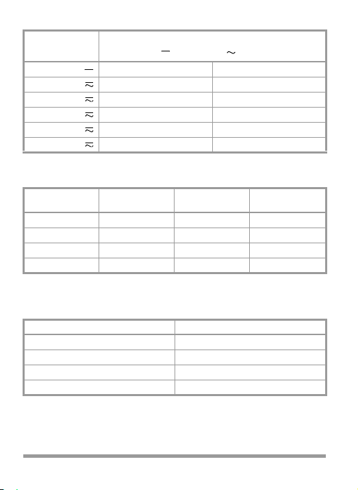
Voltage Measuring Ranges
)
Voltage Output
1
0.15 V — 3.15 kΩ —
0.50 V — 10.00 kΩ —
1.50 V –15 ... + 6 dB 31.50 kΩ 6.50 kΩ
5.00 V – 5 ... + 16 dB 100.00 kΩ 20.00 kΩ
15.00 V + 5 ... + 26 dB 315.00 kΩ 65.00 kΩ
50.00 V +15 ... + 36 dB 1.00 MΩ 200.00 kΩ
150.00 V +25 ... + 46 dB 3.15 MΩ 650.00 kΩ
500.00 V +35 ... + 56 dB 10.00 MΩ 2.00 MΩ
1)
0dB 0.775 V in the range of 1.5 V ; 0 dB 1 mW at 600 Ω
Internal Resistance approx.
Input resistance in relation to voltage for : 20.0 kΩ/V
for : 4.0 kΩ/V
METRA HIT 1A: Current Measuring Ranges
Current
50.00 μA 0.158 V —
0.50 mA 1.15 V 1.00 V
5.00 mA 1.25 V 1.25 V
50.00 mA 1.25 V 1.25 V
500.00 mA 1.85 V 1.85 V
5000.00 mA 1.73 V 1.73 V
GMC-I Messtechnik GmbH 19
www.GlobalTestSupply.com
Voltage Drop approx.
Page 20
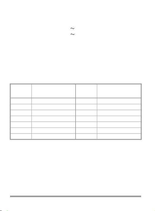
METRA HIT 2A: Current Measuring Ranges
Current
50 μA 0.158 V —
1.5 mA 1.16 V 1.21 V
15 mA 1.25 V 1.25 V
150 mA 1.25 V 1.25 V
1.5 A 1.95 V 1.95 V
15 A 0.43 V 0.49 V
Voltage Drop approx.
Resistance Measuring Ranges
Resistance Measuring Limits
Ω x 1
Ω x 10
Ω x 100
Ω x 1000
2)
for battery voltage 1.5 V
1 Ω ... 1 kΩ
10 Ω ... 10 kΩ
100 Ω ... 100 kΩ
1kΩ ... 1 MΩ
Value at Mid-Scale
)
(R
i
18.00 Ω 83 mA
180.00 Ω 8.3 mA
1.8 0 kΩ 0.83 mA
18.00 kΩ 0.083 mA
Max. Meas. Current
2)
approx.
I
max
Capacitance Measuring Ranges
Capacitance
3)
Measuring Limits
μF x 1000 2000 ... 200 000 μF
μF x 100 200 ... 20000 μF
μF x 10 20 ... 2 000 μF
μF x 1 2 ... 200 μF
3)
Estimated measurement in the resistance measuring ranges;
determination of measured values via comparative scale, see chapter 4.6.
20 GMC-I Messtechnik GmbH
www.GlobalTestSupply.com
Page 21

Reference Conditions
Ambient temperature +23 ° C ± 2 K
Position of use horizontal
Frequency 40 ... 60 Hz
Wave shape for : sinusoidal
Relative humidity 40 ... 60%
The instrument features half-wave rectification and is calibrated
in r.m.s. values. It evaluates the arithmetical mean of a half-wave
and indicates different values for undulatory voltage or current,
depending on the polarity of connection.
For other influencing quantities
according to IEC/EN 60 051
Ambient Conditions
Storage temperatures –25 ... 65 °C (without battery)
Relative humidity
max. 75%, no condensation allowed
METRA HIT 2A: Accuracy
(for reference conditions per IEC/EN 60 051),
Class 2.5 for and ;
maximum permissible intrinsic error in the 15 A : range: ± 2%;
1,5 V~: +1/–2,5%
Class 2.5 for Ω (error in relation to a scale length of 52 mm)
METRA HIT 2A: additional accuracy class influence and nominal ranges of use
Ambient temperatures
for : 0 ... +23 ... + 40 ° C
for : + 13 ... + 23
... +35 °C
Frequency Ranges 1.5 V ... 500 V:
35 ... 40 ... 60
... 1000 Hz
Ranges 1.5 mA ... 1.5 A:
35 ... 40 ... 60
... 1000 Hz
Range 15 A:
... 1000 Hz
Other influencing quantites
40 ... 45 ... 60
according to IEC/EN 60 051
GMC-I Messtechnik GmbH 21
www.GlobalTestSupply.com
Page 22

Power Supply
Battery for resistance
measurement 1 mignon cell 1.5 V per IEC LR6/R6
(AA-Size), leak-proof
Elektrical Safety
Protection class II per IEC/EN 61 010-1:2001/
VDE 0411-1:2002
Measuring category II
Nominal voltage 500 V
Test voltage 3.5 kV~
Contamination level 2
Fuses
replaceable
METRA HIT 1A:
F1: FF630mA/700V AC (50 kA), 6.3 x 32 (Article number: Z109J)
F2: FF6,3A/500V AC (50 kA), 6.3 x 32
(Article number: Z109K)
METRA HIT 2A:
F1: FF1,6A/700V AC (50 kA), 6.3 x 32
F2: FF16A/500V AC (50 kA), 6.3 x 32
(Article number: Z109E)
(Article number: Z109A)
pigtail fuse
750 mA/600 V AC
Electromagnetic Compatibility (EMC)
Interference emission
Interference immunity
EN 61326-1:2006 class B
EN 61326-1:2006
EN 61326-2-1:2006
22 GMC-I Messtechnik GmbH
www.GlobalTestSupply.com
Page 23

METRA HIT 1A: Overload capacity
Range loadable up to Range loadable up to
0.15 V –
0.5 V –
1.5 V –
5.0 V –
15.0 V –
50.0 V –
150.0 V –
500.0 V –
50.0 μA –
0.5 mA –
5.0 mA –
50.0 mA –
500 .0 mA –
5 000.0 mA –
20 V
50 V
100 V
150 V
250 V
250 V
300 V
500 V
1.0 mA
5.0 mA
10.0 mA
70.0 mA
500.0 mA
3.0 A
5.0 A
1)
2)
2)
2)
2)
2)
2)
2)
3)
—
—
1.5 V
5.0 V
15.0 V
50.0 V
150.0 V
500.0 V
—
0.5 mA
5.0 mA
50.0 mA
500 .0 mA
5 000.0 mA
10.0 mA
70.0 mA
500.0 mA
METRA HIT 2A: Overload capacity
Range loadable up to Range loadable up to
0.15 V –
0.5 V –
1.5 V –
5.0 V –
15.0 V –
50.0 V –
150.0 V –
500.0 V –
50 μA –
1.5 mA –
15 mA –
150 mA –
1.5 A –
15 A –
1)
Fuse F1 blows in the event of an overload
2)
These ranges are protected against overload by a PTC thermistor
3)
max. 1 min
20 V
50 V
100 V
150 V
250 V
250 V
300 V
500 V
1.0 mA
5.0 mA
20.0 mA
150.0 mA
1.2 A
1.5 A
12.0 A
15.0 A
1)
2)
2)
2)
2)
2)
2)
2)
3)
3)
—
—
1.5 V
5.0 V
15.0 V
50.0 V
150..0 V
500.0 V
—
1.5 mA
15 mA
150 mA
1.5 A
15 A
20.0 mA
150.0 mA
—
—
25 V
50 V
150 V
250 V
300 V
500 V
—
5.0 mA
3.0 A
5.0 A
—
—
25 V
50 V
150 V
250 V
300 V
500 V
—
5.0 mA
1.2 A
1.5 A
12.0 A
15.0 A
2)
2)
2)
2)
2)
2)
3)
2)
2)
2)
2)
2)
2)
3)
3)
GMC-I Messtechnik GmbH 23
www.GlobalTestSupply.com
Page 24
Mechanical Design
Scale length A, V – 0 ... 5.0: approx. 83 mm
A, V – 0 ...15.8: approx. 77 mm
A, V 0 ... 5.0: approx. 67 mm
A, V 0 ... 15.8: approx. 59 mm
Ω∞... 0: approx. 52 mm
dB – 15 ... + 6: approx. 42 mm
Dimensions 92 x 126 x 45 mm
Weight approx. 0.3 kg without battery
Protection type Housing IP 40, terminals IP 20
per EN 60529/VDE 0470 part 1
Extract from table on the significance
of IP codes
IP XY
(1st digit X)
Protection against the
penetration of solid
foreign matter
0 no protection 0 no protection
1 ≥ 50.0 mm
2 ≥ 12.5 mm
3 ≥ 2.5 mm
4 ≥ 1.0 mm
5 protection from dust 5 hoseproof
6 dustproof 6 extremely hoseproof
∅
∅
∅
∅
IP XY
(2nd digit Y)
Protection against the
penetration of water
1 vertical dripping
2 dripping (15° gradient)
3 spray-water
4 splashwater
24 GMC-I Messtechnik GmbH
www.GlobalTestSupply.com
Page 25

6 Maintenace
Attention!
!
6.1 Battery
The state of the battery should be checked from time to time. A
discharged or decomposing battery should not be left inside the
instrument. The battery should be checked and changed in the
manner described in chapter 4.2.
6.2 Housing
No special maintenance is required for the housing. Keep outside surfaces clean. Use a slightly dampened cloth for cleaning.
Avoid the use of cleansers, abrasives or solvents.
6.3 Fuses
The instrument is fitted with two replaceable fuses F1 and F2.
For replacement: Open and close the housing as described in
chapter 4.2 under the heading „Inserting the battery“.
Disconnect the instrument completely from the measuring circuit before opening the bottom part of the housing to replace
the fuse!
Upon tripping of the fuse, eliminate the cause of overload before putting the instrument back to serviceable
condition! Make absolutely sure that only the specified fuse is
used, see chapter 5!
Using a fuse with different tripping characteristics, different nominal current or different switching capacity
involves hazards for the operator and for protective
diodes, resistances or other components. The use of
mended fuses or short-circuiting of the fuse holder is not
permitted.
GMC-I Messtechnik GmbH 25
www.GlobalTestSupply.com
Page 26

Melting Fuse F1 for the mA Range and 0.15 V Range
F2
F1
The inserted F1 melting fuse for the measuring circuit up to 0.5 A
(for METRA HIT 1A) or 1.5 A (for METRA HIT 2A) can be checked
for continuity in the resistance measuring ranges, preferrably in
the Ω x 1 range when removed from the instrument. If the fuse is
defective, ∞ is indicated. The melting fuse blows if one of the
current measuring ranges or the 0.15 V range is unduly overloaded.
Melting Fuse F2 for the A Range
The fuse can be checked for continuity in the Ω x 1 range when
removed from the instrument. If the fuse is defective, ∞ is indicated.
Location of melting fuses after
removal of the bottom part of the
housing
26 GMC-I Messtechnik GmbH
www.GlobalTestSupply.com
Page 27

6.4 Device Return and Environmentally Compatible Disposal
Pb Cd Hg
The instrument is a category 9 product (monitoring and
control instrument) in accordance with ElektroG (German
Electrical and Electronic Device Law). This device is not
subject to the RoHS directive.
We identify our electrical and electronic devices
(as of August 2005) in accordance with WEEE
2002/96/EG and ElektroG with the symbol shown
to the right per DIN EN 50419.
These devices may not be disposed of with the trash.
Please contact our service department regarding the
return of old devices.
If you use batteries or rechargeable batteries in your instrument or accessories which no longer function properly,
they must be duly disposed of in compliance with the
applicable national regulations.
Batteries or rechargeable batteries may contain harmful
substances or heavy metal such as lead (PB), cadmium
(CD) or mercury (Hg).
They symbol shown to the right indicates that
batteries or rechargeable batteries may not be
disposed of with the trash, but must be delivered
to collection points specially provided for this purpose.
GMC-I Messtechnik GmbH 27
www.GlobalTestSupply.com
Page 28

7 Standard Equipment
Analog multimeter without battery, without cable set
28 GMC-I Messtechnik GmbH
www.GlobalTestSupply.com
Page 29

8 Recalibration
The respective measuring task and the stress to which your
measuring instrument is subjected affect the ageing of the components and may result in deviations from the guaranteed accuracy.
If high measuring accuracy is required and the instrument is frequently used in field applications, combined with transport stress
and great temperature fluctuations, we recommend a relatively
short calibration interval of 1 year. If your measuring instrument is
mainly used in the laboratory and indoors without being exposed
to any major climatic or mechanical stress, a calibration interval
of 2-3 years is usually sufficient.
During recalibration* in an accredited calibration laboratory (DIN
EN ISO/IEC 17025) the deviations of your instrument in relation
to traceable standards are measured and documented. The
deviations determined in the process are used for correction of
the readings during subsequent application.
We are pleased to perform DKD or factory calibrations for you in
our calibration laboratory. Please visit our website at
Center or → FAQs → Calibration questions and answers).
By having your measuring instrument calibrated regularly, you
fulfill the requirements of a quality management system per
DIN EN ISO 9001.
*
Verification of specifications or adjustment services are not part of the
calibration. For products from our factory, however, any necessary adjustment is frequently performed and the observance of the relevant
specification is confirmed.
GMC-I Messtechnik GmbH 29
www.GlobalTestSupply.com
Page 30

9 Repair and Replacement Parts Service
DKD Calibration Center
and Rental Instrument Service
When you need service, please contact:
GMC-I Service GmbH
Service Center
This address is only valid in Germany.
Please contact our representatives or subsidiaries for service in
other countries.
30 GMC-I Messtechnik GmbH
www.GlobalTestSupply.com
Page 31

10 Product Support
When you need support, please contact:
GMC-I Messtechnik GmbH
Hotline Produktsupport
Phone +49 911 8602-0
Fax +49 911 8602-709
E-Mail support@gossenmetrawatt.com
GMC-I Messtechnik GmbH 31
www.GlobalTestSupply.com
Page 32

Edited in Germany • Subject to change without notice • A pdf version is available on the Internet
GMC-I Messtechnik GmbH
Südwestpark 15
90449 Nürnberg •
Germany
www.GlobalTestSupply.com
Phone +49 911 8602-111
Fax +49 911 8602-777
info@gossenmetrawatt.com
E-Mail
www.gossenmetrawatt.com
 Loading...