

Page 1
-
GOSSEN
®
Luna-Pro
sbc
Instruction
Manua
l
7909-1057YO
Page 2
This Luna-Pro
sbc
Instruction Manual
is
more
than just
an
instruction book - it
is
actually a short
course
in
the creative use of
an
exposure meter.
Section
I offers "Basic Operating Instructions".
To
use your Luna-Pro sbc properly you need only read
and
follow the simple instructions
in
this section.
Section
II,
however, moves a step forward - to
"Getting the Most Out Of
Your
Luna-Pro sbc." Here
you can
really find out how to put the unique
versatility of your Luna-Pro sbc to work for you.
Section
III
gives you "Helpful Hints" for special
shootings - action, snow and sand, sunsets, night,
and more - the type of information you need for
that extra creativity.
And Section
IV provides you with full details
on
the
"Accessories" for your Luna-Pro sbc - to turn it into
a true exposure system.
We
sincerely hope that this manual will be of help
to you and will answer most of your exposure
measurement questions.
If
it does not, feel free to
contact your
specialist dealer.
In
addition, our Con-
sumer Service Department
is
available for help
with special requests.
2
Cong
ratu
lations!
You
now
own
one of the most advanced ex-
posure
meter,
the heart
of
the Luna-Pro
sbc
System.
The new Luna-Pro sbc System
is
the most flexible,
versatile
and adaptable photographic light measur-
i
ng
system ever devised, while at the same time
being very
simple to use.
In
order to get maximum
benefit from the
quality design and operating features of this precision instrument, please take a few
minutes to
read
this instruction manual.
Your
new Luna-Pro sbc utilizes the latest advances
in
silicon cell sensors and also high performance
electronic circuitry including integrated circuits
to
provide fast, accurate, repeatable readings under
the most
difficult professional conditions.
The Luna-Pro sbc represents a most significant
development
by
Gossen GmbH, Erlangen, West
Germany, Europe's
largest manufacturer of preci-
sion electrical instruments since
1919,
and one
of
the outstanding pioneers in exposure meter design
since
1932
.
Page 3
Table of Contents
Section
I.
Basic Operating Instructions . 5
I.
a. Zeroing the Meter . . . . . . . . 5
I.
b.
Inserting & Changing the Battery 5
I.c. Setting the Film Speed . 6
I.
d. Exposure Factor Scale . 6
I.
e.
Making a Measurement . 7
I.
f. Reading the Scales . . . 7
Section II.
Getting the Most Out Of
Your
Luna-Pro sbc .
10
II.
a.
Continuous or Stored Readings . .
10
II.
b. The Null Method of Measurement .
11
II.
c. Exposure Correction Dial .
12
Il.d. Footcandle Readings
with the
Luna-Pro sbc . . .
13
II.
e. Carrying Case . . . . . . .
14
11.1.
Methods of Measurement . .
14
Il.g. Incident Measurement . .
17
II.
h. Reflected Measurement . .
18
II.
i.
Scene Brightness Range .
19
lI.j. Color Crossover. .21
Il.k. Zone Systems . . . . . . .
21
11.1.
Film Reciprocity Failure
....
.
Il.m. Intermediate f/stops
..
.
...
.
Il.n. Intermediate Footcandle Values
and Exposure Time . . . . . . .
Section III. Helpful Hints . . . . . . .
Ill.a. Choosing Between Action Stopping
Ability and Depth-of-Field .
IIl.b . Snow&Sand .
IIl.c. Sunsets
..
.
Ill.d. Night Lighting . . .
II
I.e. Backlighting
..
. .
111.1
. Copying
.....
.
Ill.g. Excessive Skylight
Ill.h. Bellows (Extension) Factor
Section
IV.
Accessories . . . .
Section
V.
Using Luna-Pro Attachments
Section VI. Appendix . . . .
Service
.........
. . .
Specifications . . . . . . . . .
Additional Reference Material
24
24
25
26
26
27
27
28
28
29
29
29
32
37
38
39
40
.
41
3
Page 4
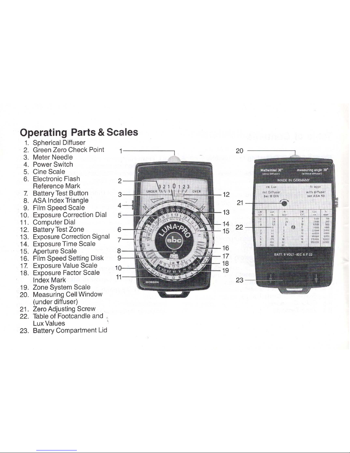
Operating Parts & Scales
1.
Spherical Diffuser
2.
Green Zero Check Point
3.
Meter Needle
4.
Power Switch
5.
Cine Scale
6.
Electronic Flash
Reference Mark
7.
Battery
Test
Button
12
8.
ASA Index Triangle
21
9.
Film Speed Scale
10.
Exposure Correction Dial
13
11.
Computer Dial
14
12.
Battery Test Zone
15
22
13.
Exposure Correction Signal
14.
Exposure Time Scale
15 .
Aperture Scale
16
16.
Film Speed Setting Disk
17
17.
Exposure Value Scale
18
18.
Exposure Factor Scale
19
Index Mark 23
19.
Zone System Scale
20.
Measuring Cell Window
(under diffuser)
21
.
Zero Adjusting Screw
22.
Table of Footcandle and '.
Lux Values
23 .
Battery Compartment Lid
Page 5
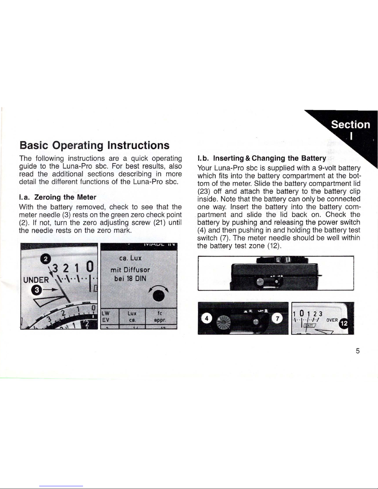
Basic Operating Instructions
The following instructions are a quick operating
guide to the Luna-Pro sbc. For best results,
also
read
the additional sections describing
in
more
detail the different functions of the Luna-Pro sbc.
La. Zeroing the Meter
With the battery removed, check to see that the
meter
needle
(3)
rests
on
the green zero check point
(2). If
not, turn the zero adjusting screw
(21)
until
the needle rests
on
the zero mark.
ca
.
Lux
mit
Diffuso~
bei
18
DIN
'e'
Ie
appr
o
I.
b. Inserting & Changing the Battery
Your
Luna-Pro sbc
is
supplied with a 9-volt battery
which fits into the battery compartment
at
the bot-
tom of the meter.
Slide the battery compartment lid
(23) off and attach the battery to the battery clip
inside. Note that the battery can
only be connected
one
way.
Insert the battery into the battery com-
partment and
slide the lid back on. Check the
battery
by
pushing and releasing the power switch
(4)
and then pushing
in
and holding the battery test
switch (7). The meter
needle should be well within
the battery test zone
(12)
.
5
Page 6
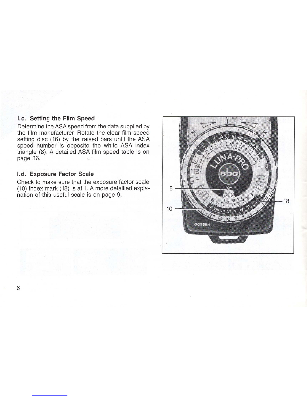
I.c. Setting the Film Speed
Determine the ASA speed from the data supplied
by
the film manufacturer. Rotate the clear film speed
setting disc
(16)
by
the raised bars until the ASA
speed number
is
opposite the white ASA index
triangle
(8).
A detailed ASA film speed table
is
on
page
36.
I.
d.
Exposure Factor Scale
Check to make sure that the exposure factor scale
(10)
index mark
(18)
is
at
1.
A more detailled expla-
nation of this useful scale
is
on
page
9.
6
Page 7
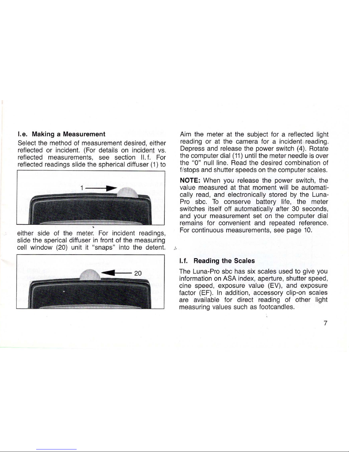
I.
e.
Making a Measurement
Select the method of measurement desired, either
reflected or incident. (For details
on
inciden1
vs
.
reflected measurements,
see
section
II.
f. For
reflected readings slide the spherical diffuser
(1)
to
either side of the meter. For incident readings,
slide the sperical diffuser
in
front of the measuring
cell
window
(20)
unit
it
"snaps" into the detent.
Aim
the meter at the subject for a reflected light
reading or
at
the camera for a incident reading.
Depress
and
release the power switch (4). Rotate
the computer dial
(11)
until the meter needle
is
over
the "0" null line.
Read
the desired combination of
f/stops and shutter speeds
on
the computer scales.
NOTE: When
you
release the power switch, the
value measured
at
that moment will
be
automati-
cally read,
and
electronically stored
by
the Luna-
Pro
sbc.
To
conserve battery life, the meter
switches itself off automatically after
30 seconds,
and
your measurement set
on
the
computer dial
remains for convenient
and
repeated reference.
For
continuous measurements,
see
page
10.
I.
f.
Reading the Scales
The Luna-Pro sbc has six scales used
to
give
you
information
on
ASA index, aperture, shutter speed,
cine speed, exposure
value
(EV)
, and exposure
factor (EF).
In
addition, accessory clip-on scales
are available for direct reading of other light
measuring
values such
as
footcandles.
7
Page 8
The time, or shutter speed scale
is
calibrated from
1/4000 of a second to 8 hours
and
indicates values
as
follows:
Hours are indicated 8h, 4h, etc.
Minutes are indicated
30m,
15m
, etc.
Seconds are indicated 30, 15, etc.
Fractional seconds are indicated '2, '4, etc.
Note that each section
is
alternately colored from
the
adjacent sections for ease of reading. The
red
A/
indicates the proper reading point when using the
electronic flash attachment. See page
34.
The ASA scale
is
calibrated
in
standard ASA values
from 0.8 to
100
,000 (100K). Intermediate values
are shown
by
short lines. A complete table listing
these intermediate values
is
on
page 38.
CAUTION: Because of the extreme measuring
range of the
Luna-Pro sbc, it
is
possible - under
exceptional conditions of very high
or
low light
levels
combined with a very high or low ASA index
- that the computer
displays both ends
of
the expo-
sure time
scale (8h and 1/4000 sec.) When this
occurs, the CORRECT reading
will
be
the
UPPER
part
of
the scales!
8
EXAMPLES:
ASA 25,000
at HIGHEST LIGHT LEVEL:
Scales.show
(above) 1/4000 sec. at
11128
but also (below) 8 hours at f/5.6 etc.
Obviously, HIGH ASA and HIGH light level add
up
to SHORT exposure - 1/4000 sec.
at
f/128.
ASA 0.8 at LOWEST LIGHT LEVEL:
Scales
show (above) 8 hours
at
f/2.8 etc.
but
also (below) 1/4000 sec. at f/64
etc.
Obviously
LOW
ASA and
LOW
light level
add
up
to
LONG
exposure - 8
hours
at f/2.8.
The
apertu~e
or flstop scale
is
calibrated from fl
128
to f/
O.7.
Numerical values are shown
on
the scale
at
full flstop increments. Intermediate values are indicated
by
short lines
at
1/3 stop increments. A table
of intermediate values
and
the mathematical
for-
mula for calculating f/stops are given
in
section
III.
The zone system scale indicates values from I
to
IX. These are the values commonly used
in
various
zone systems and represent a continuous grey
scale
of
print values ranging from black to white.
Further
explanation
on
use
of
zone system scales
are given
in
Section
II.
k.
.
Page 9
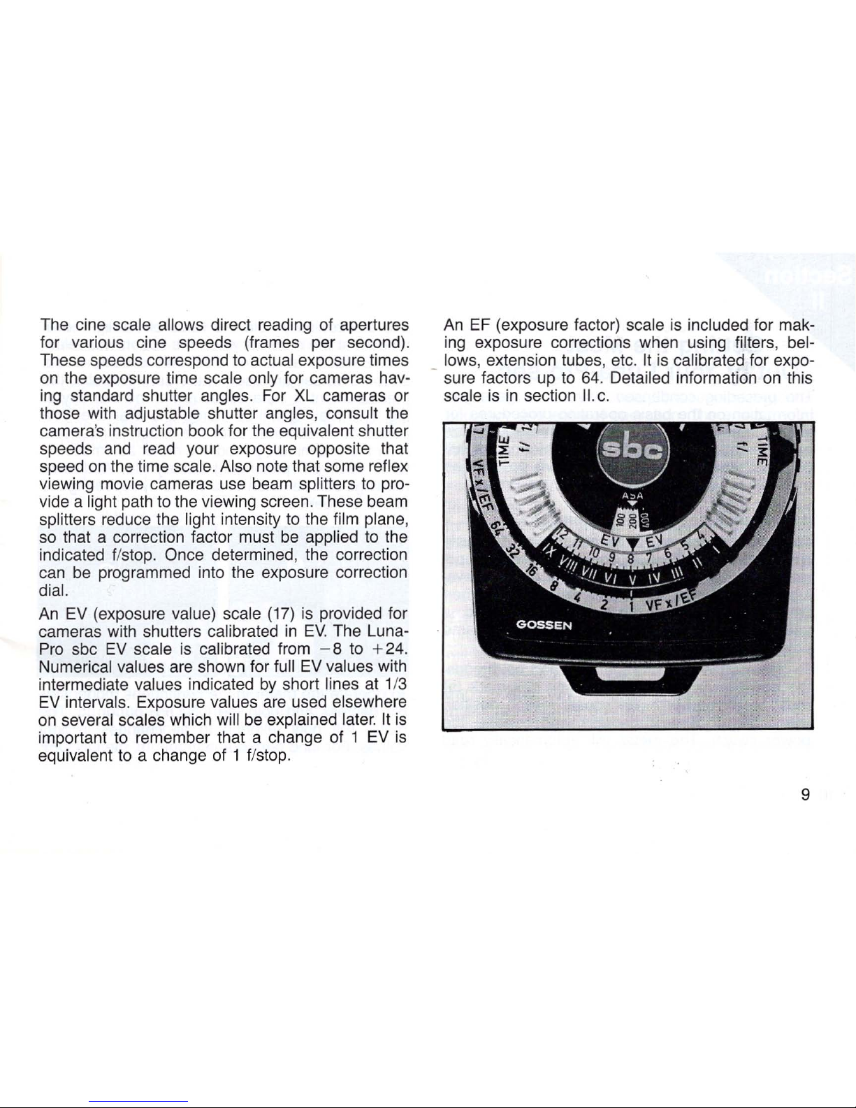
The cine scale allows direct reading of apertures
for various cine speeds
(f
rames per second).
These speeds correspond
to
actual exposure times
on
the exposure time scale only for cameras hav-
ing
standard shutter angles. For
XL
cameras or
those with
adjustable shutter angles, consult the
camera's instruction book for the
equivalent shutter
speeds
and
read your exposure opposite that
speed
on
the time scale. Also note that some reflex
viewing movie cameras use beam splitters
to
pro-
vide a
light path
to
the viewing screen. These beam
splitters reduce
the
light intensity
to
the film plane,
so
that a correction factor must
be
applied
to
the
indicated
f/stop. Once determined, the correction
can
be
programmed into the exposure correction
dial.
An
EV
(exposure value) scale
(17)
is
provided for
cameras with shutters
calibrated
in
EV.
The Luna-
Pro
sbc
EV
scale
is
calibrated from
-8
to
+24.
Numerical values
are
shown for full
EV
values with
intermediate
values indicated
by
short lines at 1/3
EV
intervals. Exposure values
are
used elsewhere
on
several scales which will
be
explained later.
It
is
important
to
remember that a change of 1
EV
is
equivalent
to
a change of 1 f/stop.
An
EF
(exposure factor) scale
is
included for mak-
ing
exposure corrections when using filters, bel-
_ lows,
extension tubes, etc.
It
is
calibrated for expo-
sure factors
up
to
64.
Detailed information
on
this
scale
is
in
section
II.
c.
9
Page 10
10
Getting the Most
Out of
Your
Luna-Pro sbc
The preceding condensed instructions gave you
information
on
the basic operating procedures for
your
Luna-Pro sbc. However, this meter
is
extremely versatile, and the following information will
acquaint you with the many creative possibilities
available
to you when using your Luna-Pro sbc.
Il.a. Continuous or Stored Readings
The Luna-Pro sbc
is
capable of either continuously
reading or storing light values. For simplicity of operation, the
read
and hold method
is
used. For eva-
luation of different lighting levels such
as
when
using zone systems, the continuous method
is
used. Both methods are activated
by
the same
power switch.
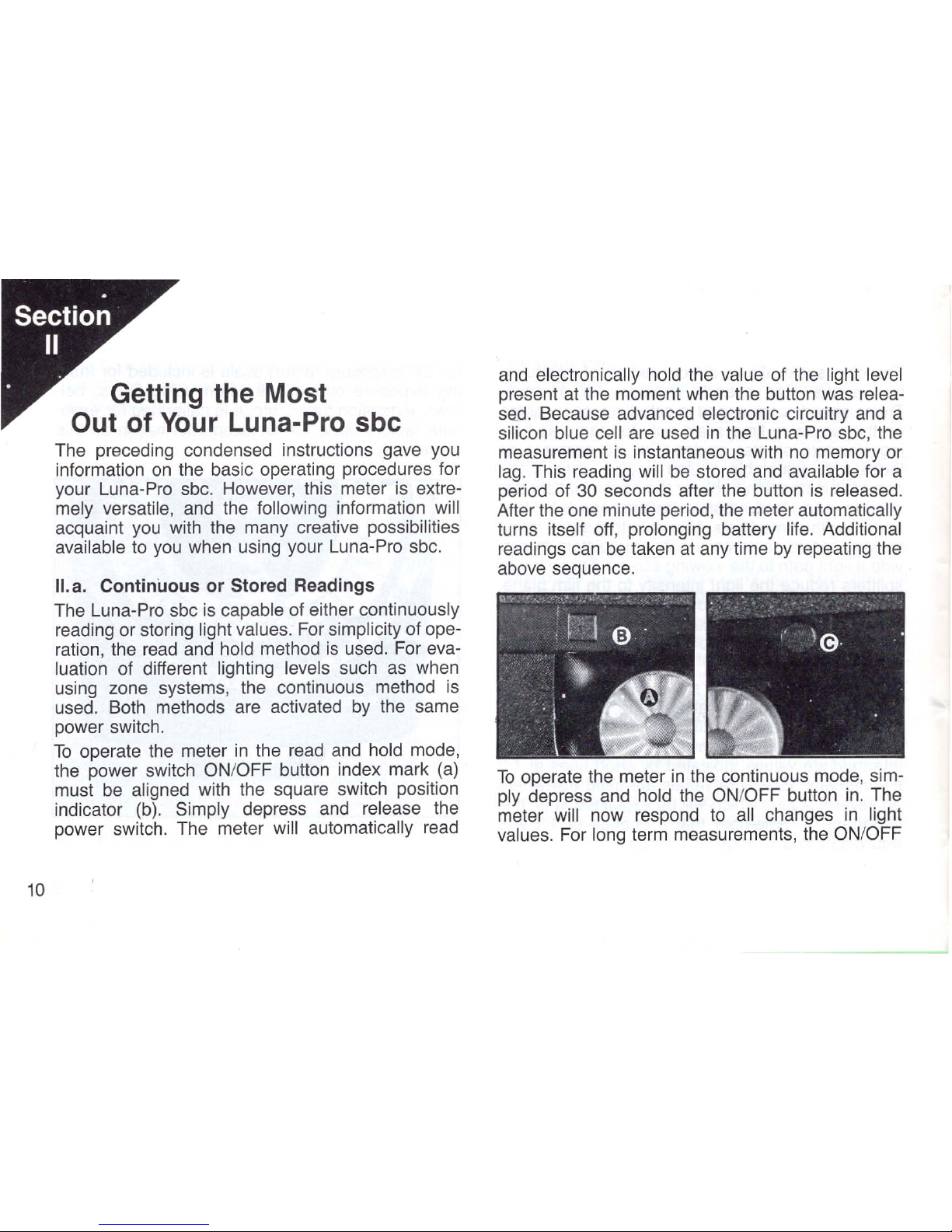
To
operate the meter
in
the
read
and
hold mode,
the power switch
ON
/OFF button index mark
(a)
must
be
aligned with the square switch position
indicator
(b).
Simply depress and release the
power switch. The meter
will automatically read
and
electronically hold the value of the light level
present
at
the moment when the button was relea-
sad.
Because advanced electronic circuitry
and
a
silicon blue cell are used
in
the Luna-Pro sbc, the
measurement
is
instantaneous with
no
memory or
lag.
This reading will
be
stored and available for a
period of
30
seconds after the button
is
released.
After the one minute period, the meter automatically
turns
itself off, prolonging battery life. Additional
readings can be taken
at
any time
by
repeating the
above sequence.
To
operate the meter
in
the continuous mode, sim-
ply depress and hold the
ON
/OFF button
in.
The
meter
will now respond
to
all changes
in
light
values.
For long term measurements, the ON/OFF
Page 11
switch has a lock position which
is
indicated
by
the
round switch position indicator
(c).
To
activate and
lock the meter on:
1)
Depress and hold the power switch
in.
2)
Rotate the switch button clockwise until the
index mark
is
aligned opposite the round switch
position indicator.
The meter
will now remain
on
for constant readings
until the switch button
is
rotated counterclockwise
opposite the square position indicator where the
read
and
hold mode will
go
into operation for one
minute, after which the meter
will again turn itself
off.
NOTE:
Be
sure to return the switch button
to
the
read
and
hold position (square mark) after using.
Failure
to
do
so
will result
in
short battery life.
II.
b.
The Null Method of Measurement
Laboratory instruments have
long used the null
method of measurement for obtaining precise readings. This method has been incorporated into
your
Luna-Pro sbc for maximum accuracy and
ease of reading.
The basic operating difference between the Luna-
Pro
sbc and a conventional meter
is
that, instead of
using various points
along a complete scale length,
only
one position (the null point)
is
used for all rea-
dings and at
all light levels. This results
in
greater
accuracy and ease of operation. There
is
no need
to change
scale ranges or
to
read different scales.
When the needle
is
set
at
the null point, the compu-
ter
instantly shows a complete read-out of the mea-
surement.
To
expand the capabilities of the Luna-Pro sbc
further, its meter face
is
also calibrated
in
1/3
EV
increments from the null position to ± 3
EV
for use
in
scene brightness measurements
and
zone
system
applications. Additional information
on
this
extremely useful feature will
be
found
in
section
II.
i.
If
the meter needle
is
placed
in
the "over" or
"under" range, the readings
on
the calculator dial
will result
in
over or underexposure
by
the value
indicated, compared to a standard exposure.
Each
numerically indicated major division
on
the
meter face
equals one
EV
(a change
of
one EV
equals a change
by
one flstop or one shutter speed
setting); the
small intermediate dots are equal to
1/3
EV.
11
Page 12
II.
c.
Exposure Correction Dial
Occasionally,
the indicated exposure readings
obtained with any
light meter must
be
modified for
best
results. This
is
especially true when using fil-
ters or when taking close-up pictures where the
longer lens to film distance results
in
reduced light
at
the film plane.
To
correct for these effects, com-
monly called filter
factor and bellows (extension)
factor,
additional exposure must be given to the
film.
In
addition, you may, for various creative
reasons, wish to depart from the standard
exposure values. For these situations, the Luna-Pro
sbc, with its exposure correction dial,
is
ideal.
Normally
when making exposure corrections, the
correction factor must be
calculated and applied
each time a reading
is
taken. However, with the
Luna-Pro sbc, the exposure change can be programmed into the exposure correction dial. Any
readings then
will automatically be corrected
as
taken.
The exposure correction
dial
is
calibrated
to
work
both
in
EV (exposure value)
and
EF (exposure fac-
tor).
Two
index marks are provided at the center or
normal positions for each correction method.
In
addition, the
red
exposure correction signal gives a
12
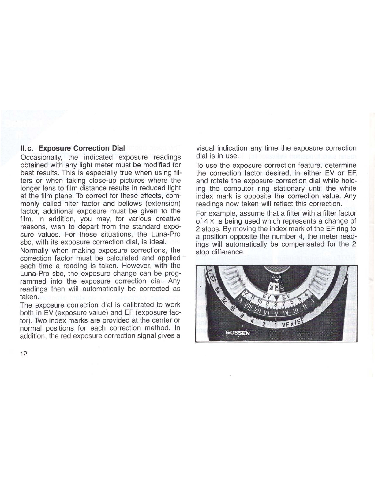
visual indication any time the exposure correction
dial
is
in
use.
:fo
use the exposure correction feature, determine
the correction factor desired,
in
either
EV
or
EF,
and rotate the exposure correction dial while holding the computer
ring
stationary until the white
index mark
is
opposite the correction value. Any
readings now taken
will reflect this correction.
For
example, assume that a filter with a filter factor
of 4 x
is
being used which represents a change of
2 stops. By moving the index mark of the
EF
ring to
a position opposite the number 4, the meter
read-
ings will automatically
be
compensated for the 2
stop difference.
Page 13
Rotating the exposure correction dial corrects the
indicated exposure by changing the shutter speed
(and
flash symbol), cine speed, and EV scales.
Therefore, this feature can
be
used for still photo-
graphy using available light and artificial ligth
including flash,
motion picture photography, and
wi
th
cameras calibrated only
in
EV.
After completing "corrected" measurements, be
sure
to
return the correction dial
to
its "0" posi-
tion (red signal will
be
covered by\ black tab).
ILd. Footcandle Readings
With The Luna-Pro
sbc
The Luna-Pro sbc
is
a precision instrument
designed to give
highly accurate photometric read-
ings specified
in
readily usable photographic terms.
However,
footcandle readings can also be obtained
with the
Luna-Pro sbc, either by converting the
photographic reading or
by
use of
an
accessory
snap-on
footcandle scale.
A conversion table of EV to footcandle readings is
included on the underside of the meter.
To
deter-
mine the equivalent footcandle reading, set the
ASA film speed scale
to
50, slide the spherical dif-
fuser over the cell window for incident readings,
point the meter toward the
light source and take
an
EV reading (null the meter). Turn the meter over
and read the
footcandle value opposite the EV
reading just obtained.
Similarly, lux values can also
be
determined. Note that for each change of one
EV,
the footcandle level changes by a factor of
2.
This
is
because the EV scale is equivalent to a full
stop scale
in
that each change of one EV or one
f/stop
results
in
either twice or half the amount of
light. A formula suitable for calculating intermediate
values of footcandles is given
in
section
III
along
with pre-calculated values at 1/3 EV increments.
For direct reading of
footcandles,
an
accessory
snap-on
footcandle scale is supplied with the
Studio Attachment. When attached, this scale
allows
quick , direct read-out of
t~e
equivalent foot-
candle
readings without having
to
change ASA
values
or using a conversion table. Detailed
instructions for its use are included with the scale.
The most precise footcandle readings are obtained
by
means of a flat diffuser such as the one supplied
with the Studio Attachment. When using the spherical
diffuser of the Luna-Pro sbc, all the light falling
on the diffuser from
an
angle of approximately 180
0
is integrated for a final reading. Since most photo-
13
Page 14

111
II
graphic subjects are three dimensional, this results
in
more accurate photographic exposures, but can
give improper
footcandle readings.
When using the
spherical diffuser, footcandle read-
ings are most accurate when reading direct
light
beams such as from spots, are lights, etc.
II.
e. Carrying Case
Your
Luna-Pro sbc
is
supplied with
an
exceptionally
practical
carrying case.
It
is
made of smooth, sturdy
materials for long life
and
extra protection for the
meter. The handy design
and
a double zipper,
as
well
as
the belt loop make this case suitable for pro-
fessional use.
14
II.
f.
Methods of Measurement
There
are
two basic methods of obtaining measure-
ments
wit
J:1
the Luna-Pro sbc, incident and reflected
light
readings. Both methods
are
popular and when
used
properly, both
are
vaiid
and
will give good
results.
However,
to
evaluate properly
the
ways
in
which these two methods function, it
is
necessary
to
discuss briefly how the meter operates
and
how film
responds
to
light. It
is
beyond the scope of this man-
ual
to
get into a detailed discussion of sensitometry,
the
study of tone reproduction. There
are
many
excellent books available
on
the
subject, some of
which
are
listed
in
the appendix. This manual will
just relate
in
simple terms,
how
the Luna-Pro sbc
works
and
under which conditions
you
may
wish
to
use either incident or reflected light readings.
All films have characteristic responses
to
light
which, although they may vary
from
film
to
film and
with changes
in
storage
and
processing,
are
rela-
tively predictable.
This consistency of response
is
what allows
the
use of light meters
and
other photo-
graphic instruments
to
predict
the
final outcome of
an
exposure.
Page 15

Film responds
to
only a limited range of illumination
levels
before its ability
to
.record that light illumina-
tion level properly
is
lost.
Any
instrument designed_
to
measure or expose film must take that into con-
sideration. The response of
the
film
to
light
is
gener-
ally graphically illustrated
by
what
is
called a
"characteristic curve" or H & D curve, named for
Hurter and
Driffield who originated its use. Although
it
is
not
necessary
to
use
such a curve
to
determine
exposures, using one
as
an
illustration will help
in
evaluating proper light measuring techniques. A
rep-
resentative sample H & D curve for a film
is
illus-
trated below.
2.00
1.60
~
1.20
in
z
~
.80
Should::..,,
__
_
Straight Line
Toe
.
401---_-
0.30 0.60 0.90 1
.20
1.50 1.80 2.
10
2.40
RELATIVE
LOG
E
This curve shows, among other things, the change
of density of the
film
vs.
the
log
of
the
exposure.
With negative
film,
as
the exposure increases, the
negative density increases.
It
is
broken down into
three distinct regions, the toe, straight
line portion,
and
shoulder.
In
order
to
record detail properly
on
film, the light values (long exposure) should fall
within the range where they intersect the straight
line portion of the curve. If the exposure falls into the
area of the toe or
shoulder, the film will lose shadow
or
highlight detail respectively. This
is
because, once
those areas
are
reached, little or
no
change
in
film
density occurs with a change
in
exposure, and it
is
the change of density that produces differentiation
and
detail. Therefore, your light meter must give
you
an
exposure value that will adjust the measured light
so
that when
it
reaches the film,
it
will fall within the
straight
line portion of the film's recording ability.
The H & D curve shown above indicates relative
log
exposure.
However,
because different films have dif-
ferent
light sensitivity ranges which would affect the
density vs.
log
exposure
in
actual use, the meter
must
be
programmed for these differences. The
ASA film speed setting control
on
the calculator dial
of the meter accomplishes this programming.
15
Page 16

In
order for this ASA value
to
be
meaningful,
all
meters and other light measuring devices that
relate
to
photographic applications must take into
account not
only the film speed, but also the reflec-
tivity of the object being photographed. This
is
because the film does not know what the reflectivity of a particular object
is.
It
only responds to light
levels.
Therefore,
all
other conditions being equal,
a light subject with a low level of illumination may
record
on
film the same
as
a dark object with a high
level of illumination.
To
standardize these varying
conditions
and
to
allow you to work with different
meters and
films, a reflectance of 18% value and
the understanding that it represents a
"typical aver-
age"
is
the basis for readings taken with both
reflected
and
incident methods of measurement,
although under the same lighting conditions, different readings for the same scene can be obtained
when using both methods, depending
on
subject
reflectivity. This may seem strange
at
first, but it
is
true, and sometimes causes confusion.
To
elimi-
nate this confusion (something no meter or other
device can do), you must consider your subject
matter and how you want it to appear
on
the film.
For simplicity, the discussion of this evaluation
16
method will be broken down into a discussion of
incident and
reflected light measurements.
Page 17

II.
g.
Incident Measurement
When reading incident light, the spherical diffuser
is
placed
in
front of the measuring cell window
ami
pointed toward the camera,
i.
e.
opposite the sub-
ject being photographed,
so
that the diffuser will
receive the same light intensity
and
distribution
as
that falling
on
the subject. The reading at this point
indicates the strength of the
light, but does not indicate the light value reflected from the subject into
the camera
lens and onto the film.
It
does indicate
the
light value that would
be
reflected into the lens
from
an
18% average reflective subject. Therefore,
when working with subjects that are
primarily very
light
or
very dark, the incident exposure reading
rndicated
should be adjusted to compensate for the
difference
in
reflectivity from the
18
% standard.
When the subject
is
very light, decrease the expo-
sure
by
1/2
to
1 f/stop. When the subject
is
very
dark, increase the exposure
by
1/2
to
1 stop. The
amount of change
to
the exposure will depend
on
your judgement
as
to
the degree of variation
in
sub-
ject reflectivity from
an
average scene.
Situations may arise where you have extremes of
light and dark subjects, all
of
which are important
in
the same scene. Under these conditions, the meter
,
/,""
I
/ I
...
..-/'"
I
I
I
I
I
should be used
in
the reflected light method
as
described under scene brightness range and zone
systems.
Incident light readings are most valuable when
determining exposures where the subject
is
inac-
cessible
and
receives the same illumination as the
meter. They
also allow your
to
determine the indi-
vidual
strenghts of multiple light sources striking
one subject
by
reading each source independently.
In
most cases with average subject matter, the inci-
dent method
is
a fast, simple
and
accurate way
to
determine exposure.
17
Page 18

II.
h.
Reflected Measurement
When reading reflected light, the meter is pointed
toward the subject and
light reflected from the sub-
ject passes through a
collecting lens onto the
measuring
cell. This is the same type of path the
light takes when exposing film
in
your camera. The
meter cannot
"read" any single element
in
its field,
such
as
a face or highlight; it integrates all the light
reflected
throughout the measuring field, and
indicates an exposure which
will record the total
picture on the basis of
an
overall
18
% value.
In
most cases,
you
can simply use this reading to
get a
perfectly exposed picture. However, there are
a few situations where the readings
should
be
modified.
The
Luna-Pro sbc has a measuring angle of 30
0
when taking a reflected reading. The light from
all
objects within that 300 measuring range will
be
averaged
to
give you the final reading. If you have
one or more objects that are significantly
lighter or
darker than the rest of the scene, the objects
will
bias the reading away from the average.
In
cases
such
as
this, the meter should be moved
in
closer
to
the main subjects of interest or one of the acces-
sory spot attachments used to
eliminate the effect
18
of the light or dark areas.
As
an
alternative,
an
inci-
dent reading can
be
taken.
When measuring a subject that departs significar.t1y
from an
18
% reflective surface, you may wish
to
modify your readings. This
is
because the read-
ing indicated
will make the subject appear
on
the
film
as
if it were
18
% reflective.
In
certain cases, you may not want the subject
being measured to
fall into that category. For exam-
ple, if the indicated reading
is
set
in
your camera
when measuring a
brilliant white bridal gown, the
resulting image of the gown
on
the film will appear
with the same density
as
if it were
18
% gray
instead of white. Here again, you may wish
to
use
Page 19

an
incident reading or compensate the reflected
reading
by
increasing exposure. The same
is
true
for very dark objects,
i.
e.,
a black tuxedo, except
the exposure
would be decreased.
Reflected readings are particularly useful when trying
to
evaluate the relative range of reflected light
from various subjects that may have different reflec-
tivity and may
be
receiving different amounts of
light. Because the reflected reading measures the
light reaching the lens, differences
in
reflectivity
and
level of illumination are accounted
for.
Therefore, your can determine the extremes and distributi
on
of light from the scene just the way your film
will
record
it.
This technique
is
covered
in
sections
Scene Brightness Range and Zone Systems.
II.
i.
Scene Brightness Range
In
order to assure proper exposures for highlight
and shadow detail
in
scenes with a wide range of
light intensity and subject reflectivity, the extent of
the
lighting range must
be
determined. The Luna-
Pro
sbc
is
ideally suited for this type of measure-
ment because of its
null meter design.
To
utilize this function,
you
must first determine,
by
testing the limits of exposure change for highlight
Proper mete
ring
aids
in r
ecordi
ng
all
detail
of a scene.
and shadow areas from average that are acceptable to you with your film. Once this
is
done, the
calibrated reference scale
on
the meter will
automatically
indicate if you are within acceptable
limits
of the film.
For
example,
if
your testing with a particular type of
film shows that you could accept
an
exposure
UNDER
OVER
19
Page 20

change from average of UNDER (under exposure)
2 to OVER (over exposure) 21/2
EV
, your total range
would be 4
1/2
EV.
Using reflected measurement,
you
could then
read
the light from the most impor-
tant area of the scene
and
then null for that read-
ing. Then, without further adjustment of the
cal-
culator dial,
you could take light readings from high-
light and shadow areas and read the
EV
variance
of these areas.
If,
in
this case, the readings fall
within the UNDER 2 to OVER
21
/2
EV
range, your
exposures
will be good. However if for example,
your readings resulted
in
UNDER 3 and OVER 1,
you
would lose shadow detail, even though the
total range
is
still only 4
EV.
A simple solution would
then
be
to reread the shadow intensity
and
rotate
the computer
dial until the meter needle
is
opposite
2
on
the UNDER side which
is
within the film limits.
UNOE
.R
OVER
20
Then recheck the highlights which should now
read
OVER
2.
You
would then use the new exposure
setting
indicated
on
the computer dial. The scene
brightness range has not changed, but the meter
has adjusted to your exposure
so
that your are
working within the range of the
film.
To
see this
graphically
in
terms of film response see the H & D
curves
to
the right.
It
is
important to note that this exposure adjustment
method works best when using negative films
because different density
levels can be adjusted for
in
printing. With transparency films, this type of
exposure adjustment
should
be
used very carefully
because you are viewing the original without the
benefit of printing correction.
Page 21

2.00
1.60
Highlight
r:
M
ain$ubjec
l
Shadow
AO
0.0
0.30
0.60 0.90
1.20 1.50
180
2.
10
2.00
RELATIVE LOG E
1.60
Highlight
1.20
Main Subject
i
.80
~
~
40
J
0.0
0.30 0.60
090
1.20 1.
50
1.80
2.
10
RELATIVE
lOG
E
With transparencies, about 1
EV
is
the largest pra
c-
tical shift if your main subject
is
close to
18
%
reflectance.
Situations may arise where the meter shows a
range of
light intensity that
is
beyond the total
range of film acceptance.
In
these cases, the use
of
fill light to lighten shadows or a "gobon (a device
to
block or modify light such
as
a dark card) to soften highlights may be indicated. When the proper
corrective action
is
taken,
)he
scene brightness
range can again be
checked to be sure the
limits of the film are
no
t exceeded. Modify-
ing the
lighting can
also be used instead
of shifting the exp
osure as mentione d
above if so desired, as
in
the case of transp
arency film where the
main subject
is
close
to
18
% reflectance
such as with some
skin tones.
21
Page 22

lI.j. Color Crossover
The preceeding discussion concentrated
on
the
effects that
lighting can have
on
film, either black
and white
or
color.
However, with color, three sepa-
rate emulsions are
on
the f
ilm
each of whose indi-
vidual response may
be
different. In normal expo·
sure situations all three layers will track reasonably
well, resulting
in
accurate rendition of color as well
as density. However, at the extremes of exposure
levels, deviations in the characteristic response of
individual color layers of the film
can
result
in
a con-
dition called color crossover. This condition results
in a color shift
in
an
area of under or over exposure
that cannot
be
corrected without affecting the col-
ors of the properly exposed areas of
the
scene. It
is
therefore very important to avoid this condition
which shows itself
as
color shifts
in
the shadows
and highlights.
I
I.
k. Zone
System
There are times when the lighting range cannot
be
brought within the acceptable limits of the film
because of
an
inability
to
use fill or use "gobos"
such as when photographing landscapes. When
these situations arise, the exposure levels
can
be
22
adjusted so that the most important parts of the
scene receive proper exposure. This
can
be
done
with either black and white or color film. However,
some detail, either in the
highlight or shadow
areas, will
be
lost.
When using black and white f
ilm
, another
technique
is
available
to
extend the capabilites of
t
he
film
to
record extreme lighting ranges. It is
called the zone system. Instead of relying
on
stan·
dard measurements and exposure techniques, the
zone system combines special measurement
techniques, modified exposures, and altered film
processing
to
expand the range of light values that
the f
ilm
can
accept. In doing so, detail
can
be
recorded which would otherwise
be
lost.
A complete discussion of this technique is far
beyond this
manual. References
are
given in the
appendix which should help your become
familiar
with this very useful photographic tool.
The Luna-Pro sbc
is
well suited for use with most
zone systems because of its null meter principle of
operation and the zone system scale
(15).
Most
systems are based on a central zone, representing
a certain
lighting level, called Zone 5.
From
this
Page 23

l
evel
the range of light from highlight
to
shadow
is
measured and referred
to
this central zone. The
l
evel
of variance
from
the central zone determines
t
he
amo~nt
of exposure correction and processing
modification,
If
any,
that
is
needed. With most
meters, the zone equivalents must
be
marked
on
t
he
face of the meter or transferred
to
a sheet of
paper
to
correlate with changes
in
light level. How-
ever,
the Luna-Pro sbc has a zone system scale
incorporated
in the
meter readout.
To
use the zone system scales of the Luna-Pro
sbc,
you
would take a measurement of a central
zone (Zone
V),
noting the corresponding
EV
values
for each zone value. Using the
EV
scale
as
a refer-
ence point, measurements of highlight and shadow
areas
can
then
be
translated into zone values.
Example:
Take a reading of a central zone or mid-tone (i.e
.,
Zone
V)
and null the meter. Assume
the
EV
in-
dicated for Zone V is '8'. Note the
EV
values in-
dicated for t
he
other zone values. In this example:
Zone
I =
EV4
Zone
VI
=
EV
9
Zone
II = EV5
ZoneVIl = EV 10
Zone
III = EV
6 Zone VIII =
EV
11
Zone
IV=
EV7
ZoneV =
EV
8
Zone
IX
=
EV
12
Now
you
can
take a reading of a highlight area, null
t
he
meter and note the EV indicated. Assuming the
highlight reading corresponds
to
an
EV 12, the
zone value would then
be
Zone IX (see chart
above). Now, take a shadow reading, null the meter
and note the
EV
indicated. Assuming the
EV
value
is '5' the corresponding zone value would
be
a
Zone
I
I.
In the example above, Zone V (a mid-tone) is used
as a reference point; however, with a Luna-Pro sbc
y
ou
can
select any zone or light level as a refer-
ence. A reading is taken of a particular area, the
meter
IS
nulled and the
EV
value noted
(i.
e.
EV
=
7).
If you
would like that area
to
be
respresented
as
a Zone III, rotate t
he
computer dial until
EV 7 is
directly above Zone value
III.
At
this point, a read-
Ing
of the appropriate apertures and shutter
speeds will render t
he
particular area measured as
a Zone
III.
23
Page 24

The zone system scale of the Luna-Pro sbc enables you to easily measure zone system values
and establish information regarding tonal range
in
a scene.
With a little practice, you
will be amazed at the
ease of obtaining this specialized informatio
n.
11.
1.
Film Reciprocity Failu
re
A
ll
photographic exposure meters rely
on
a principle of film exposure called reciprocity, to function
properly.
Basically, the film integrates or adds up
light during exposure to produce the latent image.
Within certain limits, the same image density
is
achieved for short exposures of high intensity as
with long exposures of low intensity,
as
long as the
product of intensity times time
is
constan
t.
When
the exposure times get very long or very sho
rt,
however, this reciprocity effect
is
lost, and
an
accurate prediction of exposure, and color balance with
color films, cannot be determined solely
by
the
meter reading. It
is
therefore important to check the
instructions supplied with the film
in
use
to
deter-
mine when reciprocity failure can be expected, how
severe it
will
be,
and how to correct for it. Here
again the
Luna-Pro sbc greatly assists in exposure
24
determination because the corrective filte
rs
suggested
by
film manufacturers to adjust color
shifts from reciprocity failure have
an
effect on
exposure. These filter factors can be programmed
into the
Luna-Pro sbc, and the new, corrected
f/stop read directl
y.
II.
m.
Intermediate f/stops
The Luna-Pro sbc
is
calibrated
in
1/3 stop increments with numerical indications at full stops. A
table
is
included below with the actual numerical
values of the
1/3 stop increments listed for leve
ls
from f/0.7 to f
/1
28. Values not listed can
be
calc
u-
lated from the formula that follo
ws.
New flstop = (old f/stop)
(~
(flstop Change))
For
example,
if~ou
wish to stop down
114
stop from
f/4, take the
V2
which equals
1.414 and raise it to
the power .
25
which
is
the decimal equivalent of
1
/4
stop.
Page 25

Next multiply 4 times
1.09
Your
next flstop
is
approximately 4.4.
II.
n.
Intermediate Footcandle Values and
Exposure Times
Calculation of intermediate values of footcandles
and
exposure times
is
basically the same
as
calcu-
lation
of inteJ:mediate values of flstops except that
the
value y 2
is
replaced
by 2 in
the formula.
For
example, you have a footcandle level 1/2 stop
above
1000 as represented
on
the chart
on
the
back of the
Luna-Pro sbc.
New
footcandle level = (old level)
~
2
(flstop change))
= (1000)
(2
(.
))
= (1000)
(1.414)
=
1414
25
Page 26

Helpful Hints
III.
a.
Choosing
Between
Action
Stopping
Ability
and Depth-ot-Field
After taking a light reading with your Luna-Pro sbc,
you
will have a choice of readings to use which
may
look like this:
Time:
1/1000 1/500
tl 2 2.8
Time: 1/
60
tl 8
1/30
11
1/250
4
1/
15
16
1/
125
5.6
1/8
22
All of them will give good exposures , but,
in
terms
of photographic
results, they are all slightly differ-
ent.
When shooting action, you
generally need a faster
shutter speed
to
get a sharp photograph. Speeds
from 1/
125
to 1/1000 are generally used, with the
choice depending upon the
relative speed and
direction of
travel of the object. Objects moving
toward or away from you can be stopped with a
lower shutter speed than those moving across your
26
field.
To
create a more realistic feeling of motion
with objects moving across your
filed, use a slower
shutter_speed and pan across the field. When panning, the relative speed between the subject and
the camera
is
decreased while the relative speed
between the background and camera is increased.
This
results
in
the characteristic action shot with
the main subject sharp and the background
blur-
red.
For shutter speeds of
1/60 second and longer, the
use of a good tripod or other camera support
is
suggested to avoid camera shake and blurred pictures.
When subject speed
is
not a major factor
in
your
pictures, you may wish
to
choose a longer exposure time and stop down for maximum depth-offield. This extra depth may
be
especially important
when using
long lenses because of their relatively
shallow
depth-of-field. However, with long lenses,
camera shake is accentuated so
be
careful
to
use
a sturdy support.
Conversely, even when subject speed
is
not major
factor, you may
still wish to choose a short shutter
speed and a
larger lens opening
to
intentionally
limit
depth-of-field for selective focus. This is
Page 27

especially useful for eliminating the distraction of
cluttered backgrounds. Portraits lend themselves
ideally
to this technique.
IIl.b.
Snow
& Sand
When photographing with highly reflective surfaces
such
as
snow and sand, extreme care should be
used when using
reflected readings.
In
most cases,
an
incident reading will produce superior results for
normal subject
in
the scene, although the snow or
sand may be overexposed.
If
reflected readings are
desired, the main subject
should be metered
up
close or a spot attachment used
to
minimize the
effect of the
reflected light, unless the snow or sand
is
itself the most important part of the scene. This
is
an
ideal time
to
use scene brightness range
measurements.
III.
c.
Sunsets
Sunsets
can
present a problem
in
light measure-
ment because of brightness range. Sometimes, the
sun
itself
is
the most important part of the scene,
and
at
other times, light reflecting from clouds or
distant mountains may
be
more important.
You
should first determine what part of the scene
is
most important. Using
an
incident reading under
these conditions
will generally give you poor expo-
sures with washed-out
colors. Reflected readings
are more accurate, but some compensation
is
still
necessary for the sun or
sky.
When the sun
is
pre-
sent and most important,
read
the sun directly
and
use that exposure.
If
the sky
and
clouds are most
27
Page 28

important, read these areas, being careful not to
read direct
sunlight.
In
all
cases, if practical,
bracket exposures
on
both sides of those indi-
cated.
You
may get some very striking results that
are not apparent
to
the unaided eye.
III. d. Night Lighting
Measurement of illumination levels at night
presents several problems to good exposures.
Generally,
in
outdoor scenes, the lighting
is
not
as
uniform
as
with daylight. Bright artificial lights can
create multiple
highlights and shadows, with a tre-
mendously large brightness range.
In
addition,
direct use of the meter readings will result
in
a
28
picture that appears more like a daylight photo than
one taken
at
night.
General~y'
,
night exposures get into the area of film
reciprocity failure.
It
is
therefore important
to
know
the characteristics of your film before shooting
under these conditions .
After taking film reciprocity effects into account,
decrease your indicated exposures
by
112
to
1 stop
to
preserve the night appearance
in
your scenes.
IIl.e.
Backlighting
When the main subject of interest
is
backlit, care
should
be
exercised when taking reflected read-
Page 29

ings. Light from behind the subject entering directly
into the measuring cell of the meter will produce
reading errors
To
avoid this, take your readings up
close to the subject or use one of the spot attachments for more accuracy.
An
incident reading can
also be used, with the meter pointed toward the
camera. For the most accurate exposures,
meas-
urements should be made as described
in
the sec-
tion, Scene Brightness Range.
III.
f.
Copying
Copying places stringent demands
on
lighting to
make sure that the
detail and tonal range of the
original
is
recorded
on
the
copy.
Lights are usually
placed
to the sides
of
the copyboard to eliminate
glare
from the surface of the copy. Many people
prefer to overlight the corners of the copy
to
compensate for lens falloff. The exact amount of overlighting
varies with the individual situation, but
15-
20 %
is
common.
For copy work, the
Luna-Pro sbc can
be
used with
the copy attachment for determining exposure
and
checking evenness of illumination.
IIl.g.
Excessive Skylight
When taking reflected readings of scenes where
there are
large areas of skylight, care should be
exercised that the main subject be given the
great-
est attention either
by
tilting the meter down taking
up-close measurement or
by
using one of the spot
attachments.
As
an
alternative,
an
incident reading
may
be
used.
III.
h.
Bellows [Extension] Factor
When photographs are taken where the focus
is
at
a point other than infinity,
an
exposure correction
must be made. At most working distances, this
correction factor
is
so small that it can
be
ignored.
29
Page 30

However, when working at very close distances, it
becomes significant
and
can result
in
serious exposure errors if not corrected for. This exposure variance
is
commonly called extension factor or bel-
lows
factor.
There are
s9veral ways to correct for this effect.
Two
of the most commonly used take into account
the
lens focal length and the lens
to
film plane dis-
tance
(bellows extension).
The first method gives you
an
extension factor
which can
be
programmed into the exposure factor
ring of the
Luna-Pro sbc for direct readout of
cor-
rected exposure values. The second method gives
a corrected aperture
only.
30
I. Extension Factor =
(Lens to film plane distance)2
([ens
focal
lengtW
For example, assume a
210
mm
lens (approxi-
mately
8")
is
being used with a lens to film plane
distance of 14".
Extension Factor =
(14)
2
(W
= 196
64
= 3.
06
or approximately 3
In
this case, set the white index mark, of the expo-
sure factor
ring
opposite the number
3.
Note that
the exposure factor portion of the ring (numbers
in
black) should be used, not the
EV
position. All read-
ings
will now
be
corrected for this extension factor.
II.
Effective Aperture =
(Lens to film plane distance) (Indicated f/stop)
(Lens
focal length)
Page 31

For example, assume the same conditions as
in
Example I with an indicated flstop
of
f/
11
Effective Aperture = (14)
(11)
= 154
8
8
= 19.3 or approximately 20
In
this case, if the lens were set to f/
8,
the exposure
level would be the same as if the lens were set to
f/20, although , depth-of-field would remain the
same as for
f/
8.
Using this method, each time a dif-
ferent
flstop is chosen, the same amount of correc-
tion must be recalculated into the exposure. The
first method in conjunction with the exposure factor
ring
of
the Luna-Pro sbc is much quicker and more
flexible because once the exposure factor is programmed ,
all subsequent readings are corrected for
with additional calculations and in terms
of
all
values, not just f/stops.
Another way to determine extension factor is to
measure the magnification of the object size at the
film plane. This is especially useful when working
with
large format cameras where measurement of
the image on the ground
glass is relatively easy.
To
calculate the extension factor, measure both the
actual object size and the size of the image on the
_ ground glass. These two measurements are used
in the formula below.
EF
= ( Image Size + 1 )2
Object Size
For example, assume an object size of
2 inches
and image size of
4 inches.
EF=(~
+1Y
=
(2
+
1)
2
=(W
= 9
Setting 9 in the EF correction ring
of
the Luna-Pro
sbc will give correct exposures for this condition.
Extension and filter factors can be eliminated from
exposure reading by using the accessory fiber
optics probe and reading on the camera
groundglass. Any changes due to these factors
will
automatically be sensed and compensated for by
the meter.
31
Page 32

All
of these excellent features are only the beginning of the Luna-Pro sbc story. The wide range of
instantly interchangeable accessories set the
Luna-Pro sbc distinctly above any other light mea-
suring instrument. And, to make them even more
practical, several of them automatically reprogram
the meter response for direct reading. With these
accessories, you don't have
to
match special
marks or lines to get the right reading. Just
attaching the accessory and proceeding with the
reading
in
a normal manner is
all
that's necessary!
Luna-Sphere Studio Accessory
When working
in
the studio or with multiple sources
of
light, many professionals prefer
to
measure inci-
dent light for exposure determination. This can
be
done with the basic Luna-Pro sbc, but for greater
convenience, the Luna-sphere combines its
large
32
integrating sphere with a 360
0
swivel head plus
capability
for a flat plane diffuser into one con-
venient accessory. For photometricaly accurate
measurements of
footcandles or Lux, readings
must
be
taken on a flat diffused plane. The flat
diffuser supplied with
the
Luna-sphere makes these
measurements
possible,
and
without affecting
calibration of the instru-
ment. Footcandle mea-
surements
are
preferred
by
many cinematogra-
phers
and
lighting eng
i-
neers. Others prefer
to
use
the flat diffuser sim-
ply
because it is more
directional for incident
light than diffusing sphere. The Luna-Sphere automatically
adjusts the meter sensitvity when
in
use.
Page 33

Spot Measuring Attachments
Because of its unique versatility, the Luna-Pro sbc
System can readily cope with situations which
make it
desirable
to
use reflected light measuring
angles of less than the meter's standard 30°. These
are two accessories which
will decrease the mea-
suring anlge for "spot" readings.
Multibeam Spot Attachment
For even greater selectivity, the Multibeam® Spot
Attachment for the Luna-Pro sbc provide not only
10°
and
5°
measuring angles, but,
in
addition, a 1 °
angle for ultra precise exposure measurement. The
single lens reflex design permits measuring
and
viewing through the
same
lens, eliminating
parallax problems
which
can cause measuring
errors with twin
lens 1 °
spot meters.
The
Multibeam® Attachment focuses from
maximum measuring
accuracy,
and
provision
is
made for eyepiece
correction. With this attachment, you have the
advantages of a separate 1
° spot meter for you
Luna-Pro sbc, and it
automatically adjusts the
meter sensitivity when attached.
Variable Angle Attachment
The modestly priced Vari-Angle Attachment locks
instantly
onto the Luna-Pro sbc (or regular Luna-
Pro)
and
provides convenient selection of either
15°
or
7S
measuring angles. For reflected light readings, the normal measuring area corresponds to a
light acceptance angle of 30°.
A built-in reflex view-
finder showing the
15°
and
7.5°
measuring area
permits accurate
measurements for exposures
with telephoto lenses
and
selective readings
of various parts of the
scene
or
subject when
normal lenses are used.
33
Page 34

Luna-flash 2 Attachment
Electronic flash has become
an
extremely impor-
tant source of controlled lighting
in
the studio
as
well as
on
location. Previously, standard meters
designed to measure continuous
light could not
measure the short,
extremely bright bursts of light
from such flash units. Now, however, the flash
attachment converts your Luna-Pro sbc into a high
quality electronic flash meter! This accessory can
operate either
as
a cord-connected or cordless
meter to measure single or multiple flashes.
Both incident and reflected light readings can be
taken with
flash.
Accurate readings
can
be made
in
the range of
28.8 (as to
7360
Ixs.
For a film speed setting of
100
ASA you can read f/stops from 2.8 2/3
to
45
2/3.
In
addition to that, a 5 stop range extender
is
pro-
vided. The measuring time
is 1/125
seconds.
When
multiple flashes are required
to
achieve cor-
rect exposure at a desired f/stop
(e.
g.
for greatest
depth of
field
in
interiors or other still subjects), the
readings of successive
flashes are automatically
accumulated
within the two minute cycle to indicate
to
you how many flashes are necessary for the
desired
result.
34
Once the Luna-flash 2
is
attached to the meter,
the
intemal circuitry will
be automatically programmed.
Microscope Attachment
The Microscope Attachment utilizes the Luna-Pro
sbc measuring sensitivity for convenient and reliable
exposure measurement when taking photo-
Page 35

micrographs. The Microscope attachment fits
the
ocular tube of most
microscopes for exact
exposure determina-
tions, and
is
useful
in
measuring light intensity
for
fluorescent micro-
scopy.
Sensitivity adjust-
ment
is
automatic.
Repro [Copying Attachment]
With the Repro Attachment
on
the Luna-Pro sbc, it
is
possible to obtain exposure values of flat copy
such
as
paintings, documents,
and
photographic
prints.
The
illumination
on
the copy board can
be
mea-
sured for evenness of various points
on
the material
to
be
copied.
It
can also
be reversed for measurements of
light trans-
mitted through
slides or
other
translucent mate-
rial being copied.
Enlarging Attachment
The Enlarging Attachment will help eliminate
guesswork
in
darkroom printing.
It
determines con-'
trast
range
and
correct
exposure time
by
measuring the projected
image
on
your enlarger
easel.
After calibrations
for paper
speed,
direct
readings
of
exposure
times
are
possible,
resulting
in
savings
of
time
and
material.
35
Page 36

Fiber Optics Probe Attachment
With the flexible Fiber Optics Probe Attachment
on
the Luna-Pro sbc, measurements
can
be made
in
many areas which are usually inaccessible with
an
exposure meter.
It
is
especially suitable for macrophotography groundglass measurements, density
measurements
on
negatives or transparencies,
and for
luminous density measurements. Sensitiv-
ity adjustment is automatic.
36
Luna-Color Attachment
With the color attachment
on
the Luna-Pro sbc you
can-obtain
color temperature readings of incident
light
in
Kelvin degrees.
By
setting your film's color
sensitivity into the calculator supplied with the
attachment, you can
at
the same time determi
ne
the value of correction
filters for
the
light
being
measured.
Filter
values
are
given
in
both
deca-
mired
values
of
Kodak
®
equivalents.
Ideal
for
all
continuous spectrum
sources such
as
day-
light
and
tungsten. Not
suitable for non-continuous sources
such
as
flourescent lamps.
•
il·JR.'
llK_tlKMrilm~BT""I
...
~hI",
"'·I'IIm:f'lo.~ug!><
Kodak®
is
a trademark of Eastman Kodak
Co.
These accessories make the Luna-Pro sbc the
most
versatile
and
complete systems meter availa-
ble
today.
And, because it
is
a true system meter
where the accessories interface with the meter
electronics, future advances
in
light measurement
techniques
can
be accommodated.
Page 37

Luna-Pro Attachments
All existing attachments for the Luna-Pro can be
used with the
Luna-
Pro
sbc. However, ttlese attachments do not have the automatic adjustment feature of the
Luna-Pro sbc attachments. For direct
reading with proper exposure
values, make the fol-
lowing
exposure corrections when using your
Luna-Pro attachments with your Luna-Pro sbc
Exposure Meter.
Variable Angle Attachment
The
EV
+ section of the dial
is
used. When using
the
15°
position, set the index mark opposite
+ 1 - 1/3
EV.
When using the
7.5°
position, set the
index mark opposite
+ 3
EV.
Readings are then
taken
normally.
Repro [Copy] Attachment & Filter Optics Probe:
Set the index mark opposite + 3
EVon
your expo-
sure correction
dial.
For complete instructions
on
how
to
use these
and
other attachments with your Luna-Pro sbc, write
to
Bogen Photo Corp., 17-20 Willow
St.
,
P.
O. Box
712,
Fair
Lawn
, N.J.
07410-0712
.
37
Page 38

Appendix
Intermediate
Intermediate
Intermediate
ASA&DIN
Values
Footcandle Values
F/Stop Values
ASA
DIN
ASA
DIN
ASA
DIN
.0
16
.26 4 65
1,000
16,000
.7
2.8
11
45
0.8 0 50
18
3,200 36
.02 .33 5
82
1,260 20,160
.8
3.2 13
51
1 1 64
19
4,000
37
.025 .4
6.3
103
1,590 25,400
.9
3.5 14
57
1.2 2
80
20
5,000
38
.032
.5
8
130
2,000
32,000
1 4
16 64
1.6
3
100
21
6,400 39
.04 .63
10 164
2,500
1.1
4.5
18 72
2 4 125
22
8,000 40
.05
.79
12.7
206
3,180
1.3 5
20
81
2.5 5
160
23 10,000
41
.065 1 16
260
4,000
1.4 5.6
22
90
3 6
200
24
12,500 42
.08 1.26
20 328
5,040
1.6 6.3
25
101
4 7 250
25
16,000
43 .1
1.6 25
413
6,350
1.8
7 29
113
5
8
320 26
20,000
44 .13
2 32
500
8,000
2 8
32
128
6
9
400
27 25,000
45 .16
2.5
40 630
10,800
2.2
9 36
8
10 500
28
32,000
46
.21
3.2
51
794
12,700
2.5
10 40
10
11
650
29
40,000
47
12 12
800
30
50,000
48
16
13
1,000
31
64,000 49
20
14
1,250
32 80,000
50
25
15
1,600
33
100,000
51
32
16
2,000
34
40
17 2,500 35
38
Page 39

Your Gossen Luna-Pro sbc
is
your valuable precision instrument, made with great care and accurately calibrated.
It
deserves your
good care!
-
The battery
and
zero position tests described
on
page 5 enable you to check the proper functioning of your
Luna-Pro sbc.
If
meter
is
to
be
stored for extended periods of time, remove the battery from the meter.
Measuring comparisons of your
Luna-Pro sbc with similar or other types of exposure meters cannot be
made properly without
special laboratory equipment (optical bench).
Do
not attempt
to
open or repair your Luna-Pro sbc. Service information appears below.
Service
Should your Luna-Pro sbc require service, send the meter (direct
ly
or through
an
authorized dealer),
in
the
original packing if possible, prepaid and insured, to:
B09'"
Phot~t
"",,,ot
"'""'
P.O
.
Box
506, Ramsey,
NJ
07446-0506
(201) 818 9500
FAX
(201) 818-9177
Printed in West
Germany
A brief description of the reason for sending the meter should accompany the package.
39
Page 40

Specifications
EV Range
..
..
.
Photo
Cell .
...
.
Angle of Coverage
Sensitivity . . .
Power
Source .
Dimensions . .
Weight
..
...
Scale Ranges:
Cine Range
..
Exposure Value Range
Shutter Speeds . .
..
Lens Aperture. . . . .
Exposure
Fa
ctor Scale
ASA
Range . .
40
-;
...
.
..
.
..
. .
..
ASA
25
- 6 +
15
. . . . . . . . . .
..
Silicon Blue Cell
.
..
.
...
30
0
Reflected 1800 Incident
016
to 32,000 footcandles
in
one range
. . . . .
..
. . . . 9 volt Eveready Battery
or
9 volt Mallory Duracell® Alkaline Battery or equivalent.
Battery
Type #MN
160
4
. . . 4
3
/4
X 13/4 X 23/
4
8
1
/4
oz
. with battery
. . 4.5
to
144
fps.
. . . .
-8
to
+24
1/4,000 Sec. to 8 hours
. . . . . .
f/
O.7
to f/
128
Plus/Minus exposure indicated
in
EV
Plus exposure indicated
in
Exposure Factor
. . . . . . . . . . . . . . .
0.8 to
100
,000
Page 41

Additional Reference Material
Eastman Kodak
Co.
Kodak Publications
Rochester, New
York
14650
KODAK
Professional Photo Guide R-28
KODAK-Professional Black and White Films, 2nd
Ed
. F-5
KODAK Color Films, 6
1h
Ed.
E-77
Sensitometric and
Image Structure Data for
KODAK Color Films E-78
Basic Photographic Sensitometry Workbook
2-22-FD
Lens Extension
Tables P-300
KODAK Plates
and Films for Scientific Photo-
graphy
P-315
KODAK Filters for Scientific
and
Technical Uses, 1
51
Ed
. B-3
Stroebel, Leslie; View Camera Technique;
Hastings House Publishers, Inc
.;
New
York
,
New
York
10016
Zakia, Richard and
Todd,
Hollis; Photographic
Sensitometry;
Morgan
and
Morgan, Inc
.;
Dobbs
Ferry, New
York
10522
Sturge, John; Handbook of Photography and
Reprography
Materials, Processes and Systems;
Seventh Edition;
Van
Nostrand Reinhold
Co.
; New
York,
New
York
10001
Stimson,
A.
; Photometry and Radiometry for
Engineers;
John Wiley & Sons, Inc
.;
New
York
,
New
York
10016
Dowdell, J.
III
and Zakia, R.; Zone Systemizer;
Morgan
and
Morgan, Inc.; Dobbs
Ferry,
New
York
10522
Saunders, Norman; Photographic Tone Control;
Morgan
and
Morgan, Inc
.;
Dobbs Ferry, New
York
10522
41
Page 42

GOSSEN
®
Specifications Subject to Change Without Notice
BO""
PhO'
~
'
C,,",,'
",""'
P.O.
Box 506,
Ramsey
,
NJ
07446-0506
(201)
818·9500
F
AX
(201) 818·9177
Printed in West Germany
49116a
 Loading...