

Page 1
Online Help
Software for the Management of Test Instruments and the Generation of Test Reports
3-349-999-03
8/9.19
Page 2

1 System requirements for local and client
installation ........................................................... 5
11.1 Dashboard ..............................................................35
11.1.1 Test deadlines for objects [from
BUSINESS Professional
] .........36
2 Versions of IZYTRONIQ ......................................... 6
2.1 Introduction ..............................................................6
3 Downloading BUSINESS and CLOUD Variants ......8
4 Initial installation of BUSINESS Starter / Advanced /
Professional / Premium .......................................8
5 Initial installation of the ENTERPRISE Variant ......9
5.1 Installation Prerequisites for IZYTRONIQ BACKEND 10
5.1.1 .NET Framework 4.6.1 ................................................... 10
5.1.2 Microsoft SQL Server ..................................................... 10
5.1.3 Installing IIS in the Server Manager under Roles and Features .....11
5.1.4 SSL Certificate .............................................................. 11
5.1.5 Required Users and Rights for Installing the Backend ....... 14
5.1.6 Hardware Recommendations ......................................... 14
5.1.6.1 Server ..................................................................................14
5.2 Installing IZYTRONIQ Backend ................................16
5.2.1 Installing the Database .................................................. 16
5.2.2 Installing the Application Server ...................................... 17
5.2.3 Installing the Synchronization Service ............................. 20
5.2.4 Installing the
5.3 Installing the Frontend (client) for IZYTRONIQ
Enterprise ...............................................................24
License Activation Tool (floating services) .........22
11.1.2 Test deadlines for test devices [from BUSINESS
Professional] ............................................................... 36
11.1.3 Devices on the interface ................................................. 37
11.1.4 Users ............................................................................ 37
11.1.5 Graphic series of measurements .................................... 37
12 Main modules .....................................................38
12.1 Module for portable objects ..................................40
12.1.1 Structure of the home screen ........................................ 41
12.1.2 Function “Input, change, list” ....................................... 42
12.1.2.1 The tree view: .......................................................................44
12.1.2.2 The detailed view ..................................................................49
12.1.2.3 List views .............................................................................57
12.1.3 Sequences function ..................................................... 60
12.1.3.1 Structure and operation of sequence management ................61
12.1.4 Data import function (from the test device) ................... 62
12.1.4.1 The conflict manager ..........................................................63
12.1.5 Data export function to the test device .......................... 66
12.1.6 Test templates function ................................................. 68
12.2 Module for stationary objects ...............................70
12.2.1 Structure of the home screen ......................................... 71
12.2.2 Function “Input, change, list” ....................................... 72
12.2.2.1 Tree view .............................................................................74
12.2.2.2 Detailed view: ...................................................................... 79
12.2.2.3 List views .............................................................................87
6 Licensing ........................................................... 25
6.1 Licensing BUSINESS Starter / BUSINESS Advanced /
BUSINESS Professional / BUSINESS Premium /
EDUCATION Professional / EDUCATION Premium ... 25
6.2 Licensing ENTERPRISE Premium ...........................25
6.3 Licensing ENTERPRISE Ultimate ............................25
7 Update ............................................................... 26
8 Uninstallation ..................................................... 26
9 Login / Logout ................................................... 27
10 Basics of operation ............................................ 29
10.1 Structure of the user interface ............................... 30
10.1.1 Navigation bar ............................................................... 31
10.1.2 Status bar ..................................................................... 32
10.1.3 Toolbar ......................................................................... 33
12.2.3 Sequences function ...................................................... 90
12.2.3.1 Structure and operation of sequence management .................91
12.2.4 Data import function .................................................... 92
12.2.4.1 The conflict manager ...........................................................93
12.2.5 Data export function .................................................... 96
12.2.6 Test templates function ................................................. 99
12.3 Test device management .................................. 101
12.4 User management .............................................. 103
12.4.1 User management – BUSINESS version except Premium
variant ..................................................................... 104
12.4.2 User management – BUSINESS Premium Version and
ENTERPRISE Version ................................................. 106
12.4.3 Role management – BUSINESS Premium and ENTERPRISE
Version .................................................................... 109
12.5 Recycle bin .........................................................111
12.6 Settings ..............................................................112
12.6.1 Global settings ......................................................... 113
12.6.2 Personal settings ....................................................... 115
11 Home screen ..................................................... 34
2 GMC-I Messtechnik GmbH
12.6.3 License ...................................................................... 116
12.6.4 Catalogs .................................................................. 117
Page 3

12.6.5 Database (description for Business versions) ................119
22.1 Creating a tree structure ......................................160
12.6.6 Extending the Master Data – ENTERPRISE Version ........ 120
12.7 Synchronization (ENTERPRISE Ultimate only) ......122
12.8 Help .....................................................................123
13 Lists ................................................................125
13.1 Sort .......................................................................125
13.2 Filtering (simple) ..................................................125
13.3 Group ....................................................................125
13.4 Filter editor function ............................................126
13.5 Multi-assistant (from BUSINESS Professional) ...130
14 Print ................................................................132
14.1 Creating a test report ........................................133
15 Document management ...................................135
15.1 Viewing documents ..............................................135
15.2 Creating documents .............................................135
15.3 Deleting documents .............................................135
22.2 Data export to the test device .............................162
22.3 Data import from the test device .........................163
22.4
Test documentation – creating test reports ............. 164
23 PROFITEST – first steps ................................... 165
23.1 Creating a tree structure ......................................165
23.2 Data export to the test device .............................167
23.3 Data import from the test device .........................167
23.4
Test documentation – creating test reports
............168
24 METRAHIT – first steps .................................... 169
24.1 Push/Print – first steps .........................................169
25 NEXONIQ .......................................................... 171
25.1 License – Right of Utilization – Activation ............171
25.2 Download ..............................................................171
25.3 System Requirements of Local and Client Installation ..171
25.4 Setup of User Interface .........................................172
16 PUSH/PRINT ..................................................137
16.1 Conducting a push/print test ................................137
17 Sequence editor .............................................139
17.1 Sequence types ....................................................140
17.2 Structure and operation of the sequence editor ..141
17.3 Step types in a sequence ....................................144
18 Automatic process control for a test – remote
function ........................................................... 146
18.1 Processes without test devices ............................146
18.2 Processes with remote steps .......................147
18.3 Processes with push/print steps ..........................147
19 Working in multi-user mode (floating license) . 148
20 Data replication using the server .....................148
21 Editing report templates ................................149
21.1 Miscellaneous ......................................................149
25.5 Reading out data from test instruments the formats of
which are not compatible with IZYTRONIQ ...........176
25.6 Data import from ETC file .....................................178
25.7 Importing the converted files into IZYTRONIQ ......178
26 VIDEOS – Tutorial ............................................ 180
26.1 “Sequence editor”Function “Input, change, list” –
Portable Objects ...................................................181
26.2 Structure of the index cards – portable objects ...181
26.2.1 Creation of devices ......................................................181
26.2.2 Manual input of measured values ..................................181
26.2.3 Creation of container ....................................................181
26.2.4 Test comparison ..........................................................181
26.3 File import – portable objects ..............................181
26.4 Conflict manager – portable objects ....................181
26.5 Function “Input, change, list” – stationary objects .......182
26.6 Structure of the index cards – stationary objects 182
26.6.1 Creation of machines and systems ................................182
26.6.2 Manual input of measured values ..................................182
21.2 Object, i.e. template types ....................................149
21.3 Report template management ..............................150
21.4 Basic functionality ................................................151
21.5 Data schema ........................................................152
22 SECUTEST/SECULIFE ST – first steps ............... 160
GMC-I Messtechnik GmbH 3
26.6.3 Container ....................................................................182
26.7 Management and creation of test instruments ....182
26.8 User management – BUSINESS Version except
Premium variant ...................................................182
26.9 Global settings ......................................................182
26.10 Catalogs ................................................................182
Page 4

26.11 Lists ......................................................................183
26.11.1 Working with the list filter functions, sorting, filter editor and
column assistant ......................................................... 183
26.11.2 Working with the list, creation of Excel file .................... 183
26.11.3 Working with Multi assistant ........................................ 183
26.12 Generation of test report ......................................183
26.13 Push/Print ............................................................ 183
26.14 Sequence editor ................................................... 183
26.14.1 Sequencing for PROFITEST .......................................... 183
26.14.2 Sequencing for SECUTEST ........................................... 183
26.15 Editing report templates ......................................183
4 GMC-I Messtechnik GmbH
Page 5

1 System requirements for local and client installation
The program IZYTRONIQ runs on Windows 7, 8.1 und 10:
Minimum requirements
Software components
– Operating system: Windows 7
– .NET Framework 4.6.1*
Hardware
– CPU: Dual-core i3 > 3.4 GHz
–RAM: ≥ 2 GB
– Hard drive: at least 2 GB of free memory (depending on data volume)
– Resolution: 1280x800
Recommended
Software components
– Operating system: Windows 10
– .NET Framework 4.6.1*
Hardware
– CPU: Quad-core i7 2.8 GHz
–RAM: ≥ 4 GB
– Hard drive: at least 4 GB of free memory (depending on data volume)
– Resolution: 1920x1080
– Touch display and active pen
* Microsoft has an installation assistant to install .NET Framework 4.6.1.
GMC-I Messtechnik GmbH 5
Page 6
2 Versions of IZYTRONIQ
2.1 Introduction
IZYTRONIQ is available in 8 performance levels and configurations that provide users with a solution that is tailored to specific require-
ments. Users can add upgrades to enhance the scope of functions at any time to accommodate additional requirements. Naturally,
upgrades do not alter any existing data.
BUSINESS versions
The common denominator of the Business versions is their local installation and use on one computer. They are installed on single
devices. A separate license is required for each workstation. These versions do not support multi-user operation in networks.
It is still possible to create several users.
ENTERPRISE versions
The common denominator of the Enterprise versions is the ability to work in a team. The software is installed on several computers that
share the data in one database. Depending on the version, the data can be made available online and offline. An infinite number of
licenses can be purchased for multi-user operation to suit requirements.
EDUCATION versions
The EDUCATION versions may only be used in the areas of training and education.
• BUSINESS Starter
– Stationary objects (machinery & facilities)
– Portable objects (devices & medical devices)
– Test device management
– User management
– Push/print function
– Sequence management + sequence editor
– Catalog management and editing
– Tree structure for machinery and facilities
– Tree structure for devices and medical devices
– Tree structure for locations (facilities, buildings, levels & rooms)
– Simple universal report as a PDF
– Simple list generator (PDF, Excel)
– Red/green test analysis
Main communication features
– Import of memory structure, catalogs, sequences and measurements from the test device
– Export of memory structure, catalogs and sequences to the test device
– Data import of memory structure, catalogs, sequences and measurements from an XML file
– Data export of memory structure, catalogs, sequences and measurements to an XML file
– Data import of master data for portable objects from a CSV file
• BUSINESS Advanced
in addition to BUSINESS Starter
– Extended test reports in portrait and landscape format
– Design of individual report templates in Microsoft Word
– Company logo can be integrated in the report
– Scanned signature can be integrated in the report
– Audit-proof PDFs with checksum of report content as a QR Code
– Reports can be saved as PDF and Microsoft Word documents
– Barcode generator using the Brother printer P-Touch (accessory)
– PROFISCAN barcode generator code 128 as a list printout to replace the PROFISCAN booklet
* QR Code is a registered trademark of DENSO WAVE INCORPORATED
6 GMC-I Messtechnik GmbH
Page 7
• BUSINESS Professional EDUCATION Professional
in addition to BUSINESS Advanced
– Remote function
– Manual input of measured values
– Images/photos can be integrated in the test reports
– Document management (attachments as Word, Excel and PDF documents or photos and images)
– MULTI changes
– Dashboard function in the home screen
–Quick links
– Analysis and trend development for similar tests of one object
– Overarching statistics with percentage failure rate as a PDF printout
• BUSINESS Premium EDUCATION Premium
in addition to BUSINESS Professional
– Roles & rights management for users
– Screen designer and data field editor to customize the application
• ENTERPRISE Premium
EDUCATION Premium enables collaborative work.
An infinite number of users can access the same database at the same time.
Each user requires a separate ENTERPRISE Premium license for concurrent use of the application.
In addition to BUSINESS Professional
– Network capability – connection to an external MS-SQL database (server)
– Floating multi-user operation – with staggered license model
– Roles & rights management for users
– Screen designer and data field editor to customize the application
• ENTERPRISE Ultimate
ENTERPRISE Ultimate is an additional license for provisioning and automatic reconciliation of mobile data (data replication).
At least one license is required to use ENTERPRISE Premium.
An Ultimate license is required for each mobile workstation (outdoor/offline). An infinite volume of datasets can be exchanged, i.e. synchronized between the
server and the mobile workstation. Users can access these datasets offline at the mobile workstation
and can be edited there and then synchronized.
GMC-I Messtechnik GmbH 7
Page 8

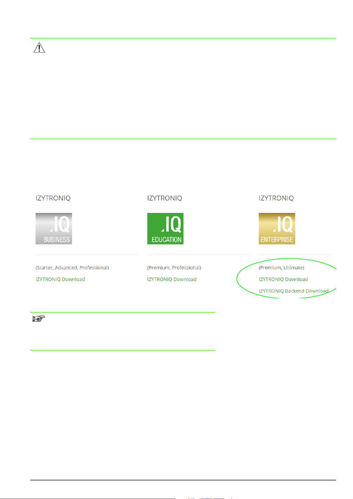
3 Downloading BUSINESS and CLOUD Variants
Different variants of IZYTRONIQ can be downloaded from https://www.izytron.com/downloads.php.
After downloading the file (IZYTRONIQ.Setup.exe), it must be stored to a directory. The setup file then appears in the selected directory.
After starting the file, follow the installation instructions (see “Initial installation of BUSINESS Starter / Advanced / Professional / Premium”.
4 Initial installation of BUSINESS Starter / Advanced / Professional / Premium
IZYTRONIQ can be installed as standalone (local) software and used exclusively on the respective PC. The application can be used with
BUSINESS Starter, BUSINESS Advanced, BUSINESS Professional and BUSINESS Premium licenses.
Installation of IZYTRONIQ is started by executing the IZYTRONIQ.Setup.exe file. Verification is first of all conducted to determine whether or
not installation is possible with the available system environment (see “System requirements for local and client installation”).
When prompted to choose Standalone, Network Version (client) or Cloud Operation, Standalone must be selected.
The user is then asked in which language IZYTRONIQ should be installed. Afterwards, either standard or user-defined installation can be
selected. In the case of user-defined installation, the directory path can be changed. After installation, you have the option of either
starting the program directly or closing the installer.
After starting the software for the first time, the license key has to be entered (see “Licensing”).
8 GMC-I Messtechnik GmbH
Page 9
5 Initial installation of the ENTERPRISE Variant
Caution!
As is the case with every client-server architecture, administrative knowledge is required in order to install the necessary backend components.
Minimum technical requirements must be fulfilled in order to operate one’s own server.
Further information is included in our installation checklist which we can make available to you upon request.
Further software components from Microsoft are also required, for example a server with MS Server operating system. This
includes MS IIS, which must be administrated for IZYTRONIQ.
Installation of the required MS SQL database also necessitates appropriate technical knowledge.
Additional license costs are incurred depending on the selected performance level of the MS SQL database.
In order to assure GDPR-compliant, secure communication between the server and the client, the data must be encrypted for
transmission. A certificate is required to this end. Detailed information concerning this certificate can be found in the corresponding passages of the respective sections.
Our industry support department would be happy to help you with installation of your IZYTRONIQ backend within the framework of a service package.
Download
IZYTRONIQ Enterprise can be downloaded from https://www.izytron.com/downloads.php.
After downloading the files (IZYTRONIQ.Setup.exe and IZYTRON.Backend.zip), they have to be saved to a directory on the server
intended for this purpose.
Important Note
Due to the fact that the Client and Backend versions are mutually dependent on each other, we always recommend running both downloads
(Backend and Client), one immediately after the other, from the above
referenced website.
Otherwise it’s not possible to rule out possible incompatibilities between Backend and Client after installation has been completed.
GMC-I Messtechnik GmbH 9
Page 10

5.1 Installation Prerequisites for IZYTRONIQ BACKEND
Windows Server 2016 or higher is recommended for installation.
The network infrastructure is dealt with in detail in the following sections, for example settings and features are described which are
required for operation of the backend.
The following attributes must be activated:
• Windows Server 2016 or later
• MS SQL Server for the database
(mixed mode authentication is recommended in the case of an MS SQL Express installation)
• MS SQL Management Studio
• Activated IIS with the corresponding features
Common HTTP features
– All except for WebDAV Publishing
Health and diagnostics
– HTTP logging
– Request monitor
Performance
– Static content compression)
Security
– Request filtering
– Basic authentication
• The following features must be activated:
Application development
– .NET Extensibility 4.6
– ASP.NET 4.6
– ISAPI Extensions
– ISAPI filters
Management tools
– IIS management console
– IIS 6 management compatibility
– Complete
.NET Framework 4.6 features
– WCF services
– HTTP activation
5.1.1 .NET Framework 4.6.1
Installation of .NET Framework 4.6.1 or later can be executed by a corresponding Microsoft installation program.
5.1.2 Microsoft SQL Server
A Microsoft SQL Server (2016 or later) must be available to which the backend can connect.
Appropriate software can be obtained from Microsoft for a license fee.
The following hardware specifications are minimum requirements which may have to be scaled up depending upon usage and utilization:
Processor Quad core CPU
RAM 8 GB
Hard disk space 100 GB
Note
The specifications in the table shown above make reference to an
IZYTRONIQ ENTERPRISE single-server installation.
10 GMC-I Messtechnik GmbH
Page 11
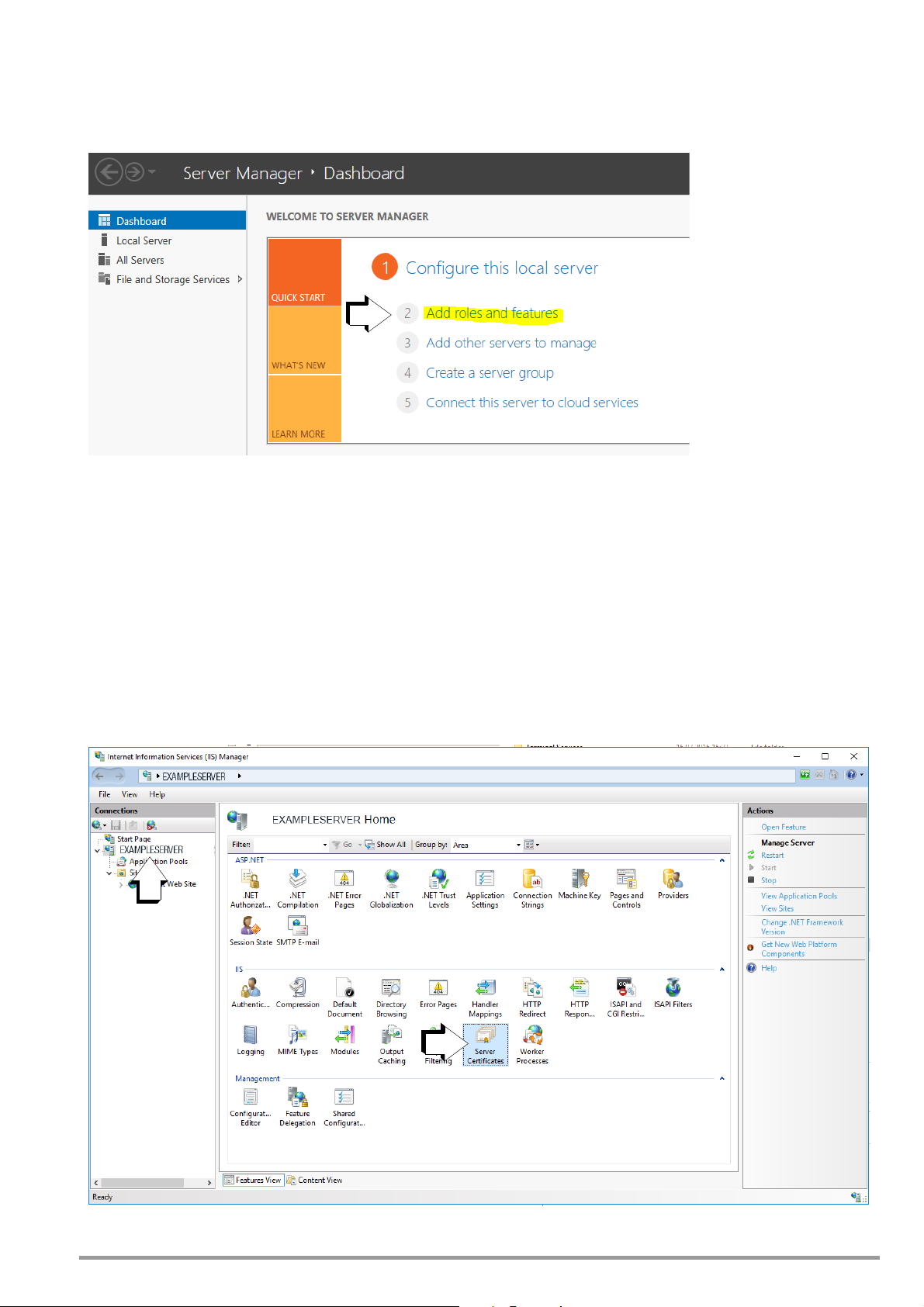
5.1.3 Installing IIS in the Server Manager under Roles and Features
The following description is based on the English version of a Windows server. Images and sequences may vary depending on server
version.
► Start the Server Manager and open the selection list by clicking Add roles and features.
The required features are listed under “Installation Prerequisites for IZYTRONIQ BACKEND”.
5.1.4 SSL Certificate
A valid certificate must be available on the server in order to be able to use the WebService and the SyncService.
This certificate provides for secure communication via https in order to ensure GDPR-compliant data exchange.
It’s advisable to obtain the certificate from an authorized source with a suitable duration of validity. A self-signed certificate can be used
as an alternative. However, these are typically limited to one year and must be installed separately to the clients in the “Trusted Root
Certification Authorities” memory location.
A description of where the certificate has to be incorporated into the IIS (Internet Information Services) is included below.
► Click Server Certificates to this end.
GMC-I Messtechnik GmbH 11
Page 12
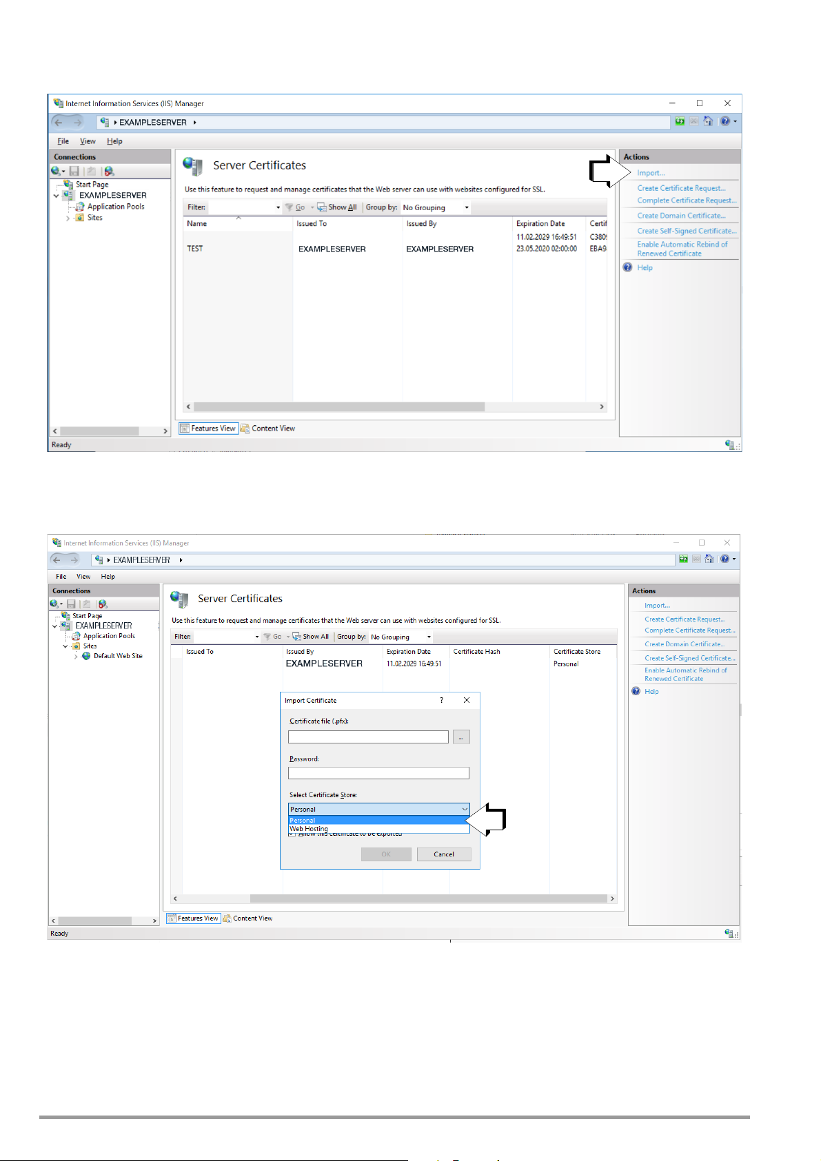
► Afterwards, the desired certificate has to be loaded to IIS via the import function.
► Select “Personal” under certificate store.
The certificate’s fingerprint is entered to the respective configuration files (IZYTRONIQ.SyncSvc.exe and Web) in uppercase letters without
blanks and without hidden special characters. It may be advisable to copy the certificate’s fingerprint into the editor and copy it, in
order to avoid errors.
12 GMC-I Messtechnik GmbH
Page 13
Note
This is only possible after successful installation of the backend’s .msi
files, which is described in more detail below beginning with “Installing
the Database”.
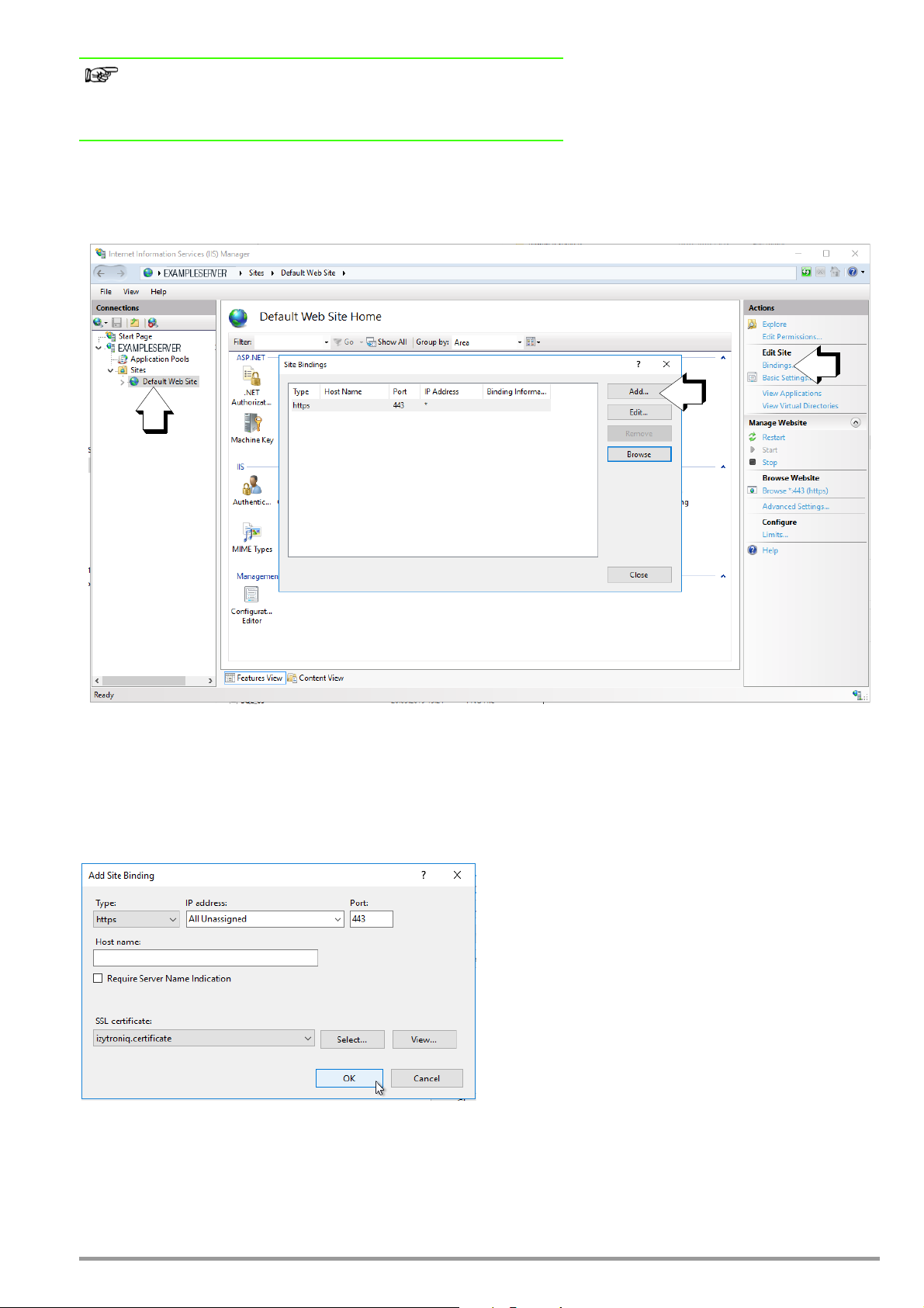
Subsequently, the certificate also has to be entered to the bindings of the default website so that communication can take place in the
case of standard installation.
A new binding must be added to the site bindings via the “Add” function. A new window appears.
It must be assured that “https” is selected under type and that “443” is selected as the port. The SSL certificate must then be selected
which was previously imported into IIS.
The “IP address” and “Host name” fields remain unchanged.
► Acknowledge your selections by clicking OK.
GMC-I Messtechnik GmbH 13
Page 14

5.1.5 Required Users and Rights for Installing the Backend
A local administrator is required in order to install and set up the backend. This user’s password must not expire or be changed. Ideally,
the server is installed directly under this user’s ID.
This user must also be set up in the SQL Management Studio and have “dbcreator” and “sysadmin” rights in order to create databases.
5.1.6 Hardware Recommendations
This section includes recommendations for the network infrastructure for operation of the Enterprise variant of IZYTRONIQ.
5.1.6.1 Server
Standard installation typically involves installation to a server on which the database, the application and the synchronization service
run. The server must be adequately dimensioned in accordance with system utilization.
Backend Server
Location: Intranet
Access: Domain access
Operating system: Windows Server 2016
Accessibility: Via HTTPS from the clients (via intranet)
Services
Name Typ e Description
IZYTRONIQ Backend Web service Provision of services for the IZYTRONIQ client
Hardware
Above all, the backend server requires as much computing power as possible.
Name Minimum Recommended
CPU 1 logical core per 10 users 1 logical core per 5 users
RAM 1 GB per 10 users 1 GB per 5 users
Synchronization Server
Location: Intranet
Access: Domain access
Operating system: Windows Server 2016
Accessibility: Via HTTPS from the clients (via intranet)
Services
Name Typ e Description
IZYTRONIQ backend sync service Windows service Service for synchronizing the client database with the
backend database and importing data from the test instruments
Hardware
Name Minimum Recommended
CPU Quad core Quad core
RAM 8 GB 16 GB
Hard disk 10 GB 15 GB
Network 100 Mbit/s ≥ 100 Mbit/s
14 GMC-I Messtechnik GmbH
Page 15

Backend Database Server
Location: Intranet
Access: Domain access
Operating system: Windows Server 2016
The database server does not necessarily require its own installation. If there’s already an existing database server with adequate
resources, this can be used as well (in an existing or a separate instance).
This offers the advantage of not having to run an additional SQL server (mirroring, backup and disaster recovery).
Services
Name Typ e Description
MS SQL server 2016 or newer MS SQL server version Database Backend database
We recommend using MS SQL server 2016 or higher.
Hardware
Hardware depends to a great extent on whether additional databases and services, or only the database for the backend server, will be
run on the server.
Name Minimum Recommended
CPU Dual core Quad core
RAM 8 GB 16 GB
Hard disk 10 GB 20 GB
Network 100 Mbit/s > 100 Mbit/s
GMC-I Messtechnik GmbH 15
Page 16

5.2 Installing IZYTRONIQ Backend
General
The backend includes 4 installation packages, all of which have to be installed to the same server, even if the database will run on a
separate server:
• Database
• Application server
• Synchronization service
• License activation tool
Installation must be started by means of a command prompt with administrative rights. The .msi files have to be executed with the
“msiexec /i” command.
In the case of a standard installation, the default values listed below are always used – even if they’re not explicitly specified. The
parameters can be optionally edited in the case of a non-standard installation.
Note
Two databases are installed to an MS SQL server provided by the customer while IZYTRONIQ Enterprise Backend is being installed. User
accounts must be provided which include corresponding rights for installation and operation of IZYTRONIQ Enterprise, in particular with rights for
accessing the MS SQL server.
5.2.1 Installing the Database
IZYTRONIQ BackEnd Database.msi
Description
This setup installs the application server’s database.
MSI Package
The MSI package includes the following optional parameters, for which the respectively used default values are specified in the following. These are used automatically if the corresponding parameter isn’t specifically configured during installation.
PRODUCT_LANGUAGE = de
BACKEND_SERVERNAME = localhost
BACKEND_DATABASE = IZYTRON.IQ
BACKEND_DATABASE_USERNAME =
BACKEND_DATABASE_USERPWD =
The last two parameters are typically only required if the database to be set up will run on another server.
Example of configuration during installation:
msiexec /i "IZYTRON.IQ BackEnd Database.msi"
BACKEND_SERVERNAME = myserver\SQLEXPRESS
PRODUCT_LANGUAGE = en
BACKEND_DATABASE_USERNAME = johndoe
BACKEND_DATABASE_USERPWD = mypassword
In the example, the database for the English language is installed to the SQL server (“myserver”) with MS SQL instance SQLEXPRESS and user “johndoe” along with
his password (“mypassword”) as “IZYTRON.IQ”.
Comments
– If the database already exists when setup is executed, it’s not deleted. If the version in the Database_Info table does not corre-
spond to setup, setup executes the corresponding update scripts in so far as an IZYTRONIQ database is involved.
– The database doesn’t necessarily have to be installed to the same server as the backend. If the connection string in the “IZY-
TRON.IQ.SyncSvc.exe.config” file is appropriately modified, the application server utilizes the correct database.
It’s advisable to determine whether or not the IZYTRONIQ database has been successfully created with the help of the MS SQL Management Studio.
16 GMC-I Messtechnik GmbH
Page 17
5.2.2 Installing the Application Server
IZYTRONIQ BackEnd ApplicationServer.msi
Description
This setup installs the application server to IIS.
MSI Package
The MSI package includes the following optional parameters:
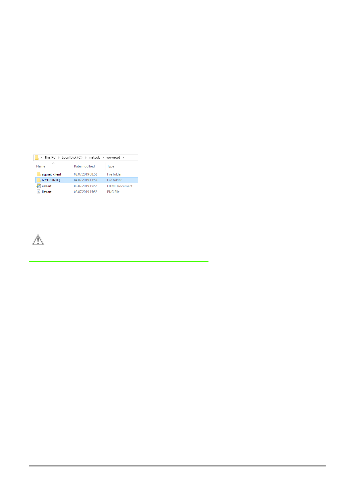
INSTALLWEBAPPDIR = standard wwwroot directory of the IIS,
normally = c:\inetpub\wwwroot\IZYTRON.IQ
WEBSITE_NAME = Default Website
WEBAPP_NAME = IZYTRON.IQ
APPPOOL_NAME = IZYTRON.IQ.BackEnd Pool
APPPOOL_USERNAME =
APPPOOL_USERPWD =
With the default settings, the application server is installed as follows:
This installs the application server to IIS under “MyWebSite\MyWebApp” (virtual directory) and physically to “c:\myinstalldir”. The application pool (IZYTRON.IQ.BackEnd Pool) (default) is set up with user name “myapppooluser” and password “mypwd”, and is assigned
to the website.
Attention!
The user designated for operative use must also always have access to
the database with read and write authority, in so far as this user is not the
dbo (database owner)!
Comments
– The application’s URL is laid out as follows:
https://<certificate path>/<application name>
The certificate path is the path which is specified in the general information for the certificate in IIS (“General” tab, issued to: <certificate path> in the “Certificate” window).
– If “IZYTRON.IQ BackEnd ApplicationServer.msi” is executed directly by double-clicking, the application server is installed as
“Default Web Site\IZYTRONIQ” with the “IZYTRON.IQ.BackEnd Pool” app pool and the following default app pool credentials: Appli-
cationPoolIdentity.
This user (ApplicationPool) probably doesn’t have any access to the database. A suitable user must be entered to this end (in the
app pool’s “Advanced Settings” under “Identity”).
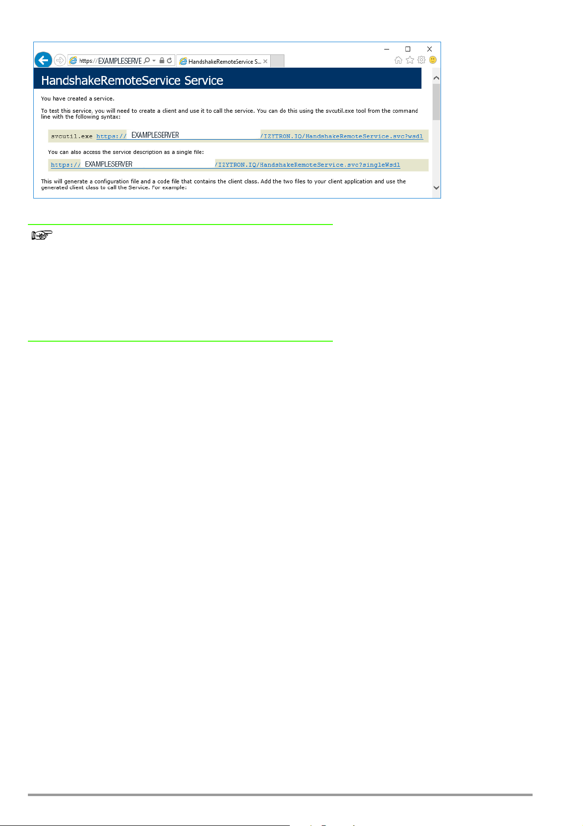
– The following URL can be opened in the browser in order to display the correct installation:
“https://localhost/IZYTRON.IQ/HandshakeRemoteService.svc” (if installed in this way).
In the event of correct installation, an information page is displayed.
https://<certificate path>/IZYTRON.IQ/HandshakeRemoteService.svc
GMC-I Messtechnik GmbH 17
Page 18
Note
However, if URL https://localhost/IZYTRON.IQ/HandshakeRemoteService.svc is used,
a certificate error is displayed as a rule in the browser because certificates are not typically issued via a certificate path including “localhost”.
The user must also assure that the certificate used for the application has
been entered or saved to the web browser which is also used for the
application. This also applies in the case of computers for which subsequent installation of an IZYTRONIQ Enterprise client is planned, if a selfsigned certificate is involved.
If the page is not displayed, a standard IIS error message appears instead, which provides information concerning any possible installation errors.
– The application uses default HTTPS port 443. The TCP port setting may not be changed.
– A valid certificate must be assigned to the page. Otherwise, the clients are unable to access the application server.
A corresponding binding with a certificate for this purpose must therefore be set up on the IZYTRONIQ backend server. When install-
ing the IZYTRONIQ backend application service with the default parameters specified above, binding to the default website must take
place in IIS (internet information services). Please refer to previous section 5.1.4, “SSL Certificate”, for details.
18 GMC-I Messtechnik GmbH
Page 19
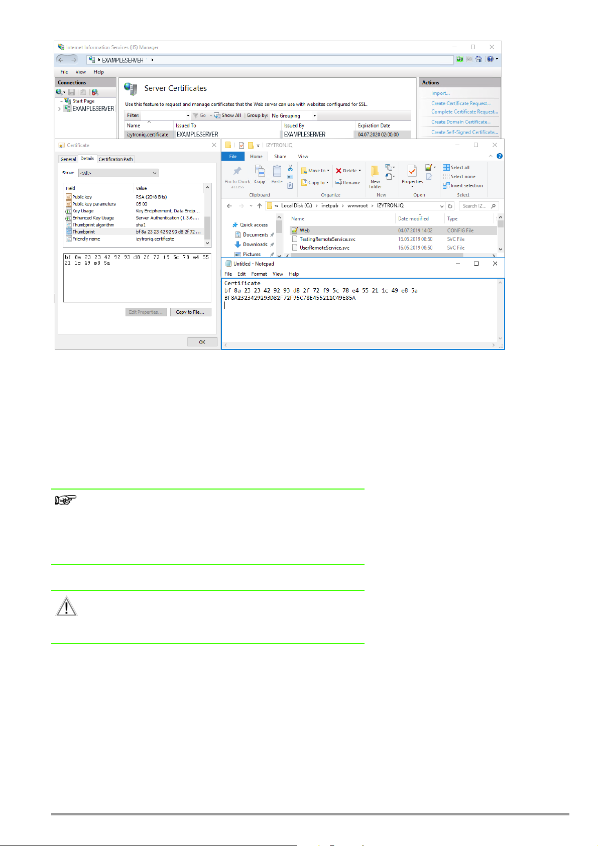
The value for “findValue” must also be correctly set in the Web.Config file under the <serviceCertificate> tag. This corresponds to the
certificate’s fingerprint or thumbprint.
As shown in the figure above, the fingerprint or thumbprint can be taken from the certificate’s details, which in turn can be found in IIS
under Server Certificates.
For the purposes of IZYTRONIQ, the fingerprint must be taken over
– without blanks,
– using uppercase letters only and
– without hidden special characters
within the <serviceCertificate> tag of the Web.config file.
Note
The Web.config file doesn’t have to be modified until modification of the
IZYTRONIQ SyncService.exe.config file becomes necessary during installation of the synchronization service (next section: “Installing the Synchronization Service”). The corresponding tag in the Web.config file can simply be replaced with the modified <serviceCertificate> tag there.
Attention!
The user of the application server’s application pool (in IIS) must be
authorized to access the database. Corresponding rights (read and write)
must be provided at the database side.
GMC-I Messtechnik GmbH 19
Page 20
5.2.3 Installing the Synchronization Service
IZYTRON.IQ BackEnd SyncService.msi
Description
This setup installs the synchronization service. It’s installed as a standalone Windows service with the name “IZYTRONIQ BackEnd SyncService”.
Comments
The service must be installed to the same server as the application server.
Configuration
– Installation directory: %Programfiles%\Gossen-Metrawatt\IZYTRON.IQ BackEnd SyncService
– The configuration file is located in the installation directory and its name is IZYTRON.IQ.SyncSvc.exe.config.
Note: If the service (IZYTRON.IQ BackEnd SyncService) has been started automatically after installation, it should be stopped for the
purpose of configuration.
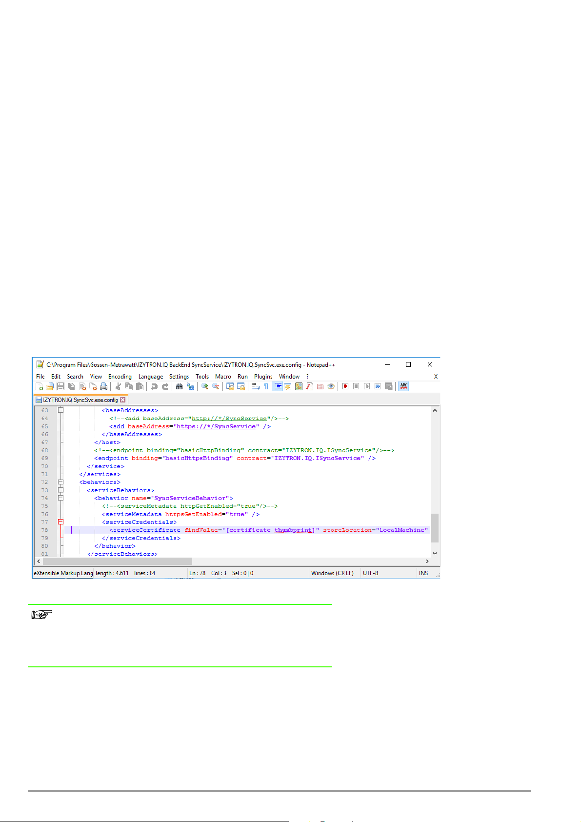
The following lines must be changed in the IZYTRONIQ.SyncSvc.exe.config file.
<serviceCertificate findValue="[certificate thumbprint]" storeLocation="LocalMachine" storeName="My" x509FindType="FindByThumbprint" />
Enter the fingerprint or thumbprint of your utilized certificate in uppercase letters without blanks in place of [certificate thumbprint].
Example:
<serviceCertificate findValue="[certificate thumbprint]" storeLocation="LocalMachine" storeName="My" x509FindType="FindByThumbprint" />
Note
The Web.config file of the IZYTRONIQ application server can be changed
by copying the modified <serviceCertificate> tag from the IZYTRO-
NIQ.SyncSvc.exe.config file and inserting it at the appropriate place in the
Web.config file.
– The connection to the local synchronization service database is configured with the name “SyncService” in the <connection-
Strings> section of the IZYTRONIQ.SyncSvc.exe file.
The path to the instance must be modified if necessary under “DataSource= (local)”, for example “DataSource=(local)\SQLEXPRESS”,
and “(local)” must be replaced with the computer’s name if applicable.
We recommend adding the following entry to the line: “;MultipleActiveResultSets=True”.
20 GMC-I Messtechnik GmbH
Page 21
Example:
<add name=“SyncService” providerName=“System.Data.SqlClient” connectionString=“Data Source=(local);Initial Catalog=SyncService;Integrated Security=True;MultipleActiveResultSets=True”/>
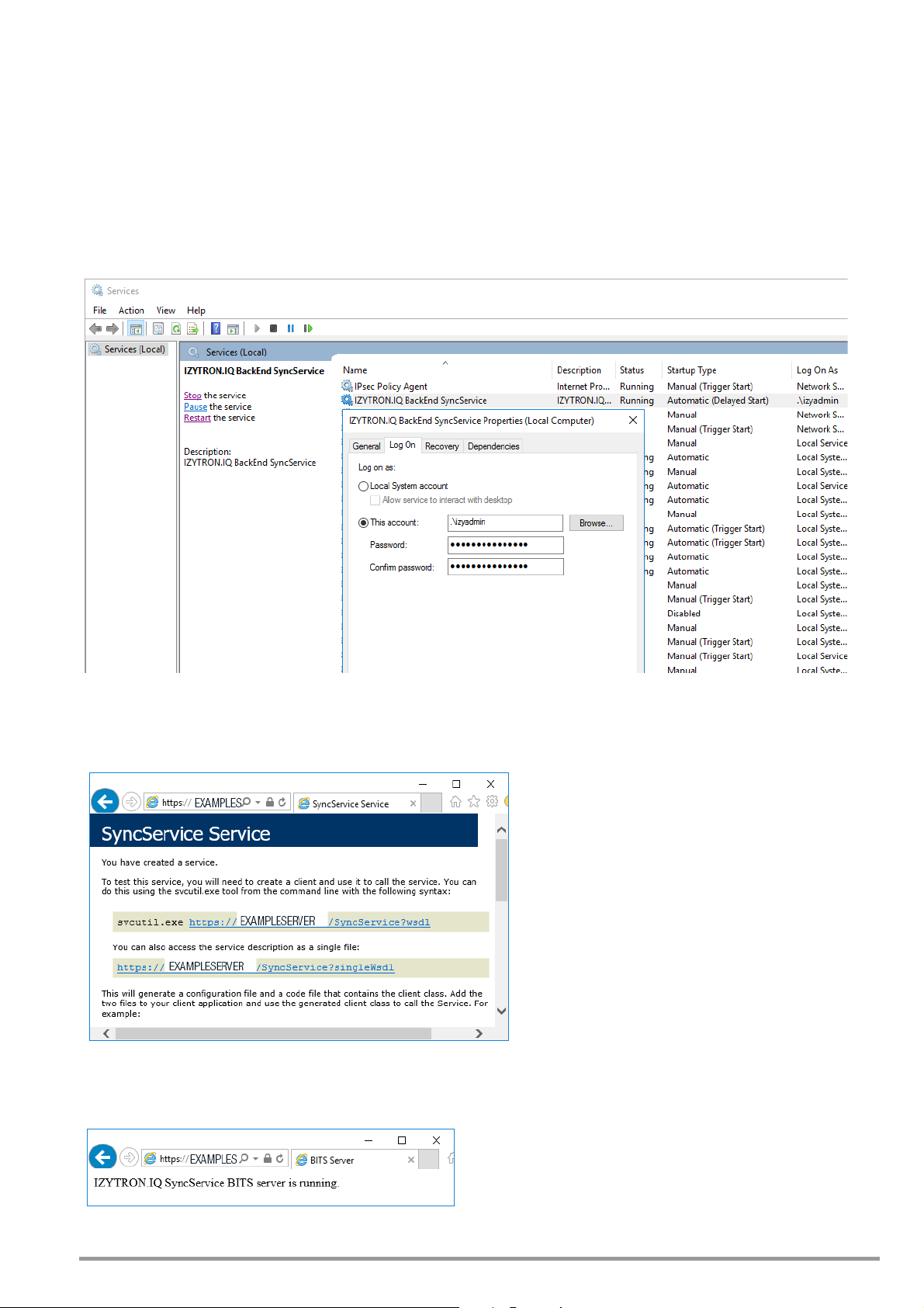
– In order to make it possible for the service to create the SyncService database when it’s started, it must be started via a user account which is
capable of creating databases.
The following figure shows an example of how the service is accordingly set up using an account which has corresponding SQL
server-side authority as a “dbcreator”.
After the service has been started, checking can be conducted to determine whether or not the “SyncService” database has been successfully created.
After it has been installed to the IZYTRONIQ backend server, the synchronization service should be checked for correct functioning with
the help of a web browser and the following link: “https://<certificate path>/SyncService”.
The synchronization service can be subjected to additional testing for correct functioning with the help of the following link:
“https://<certificate path>/bits”.
It’s advisable to set the service’s start mode to “Automatic (Delayed Start)”.
GMC-I Messtechnik GmbH 21
Page 22
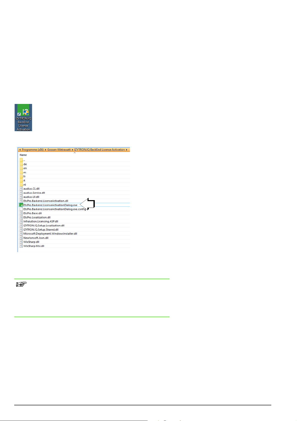
5.2.4 Installing the License Activation Tool (floating services)
IZYTRON.IQ BackEnd License Activation.msi
Description
This setup installs the license activation tool. It’s installed as a standalone program with the following name: “IZYTRON.IQ BackEnd
License Activation”.
Comments
The service must be installed to the same PC as the application server.
In order to install the service, execute the IZYTRONIQ BackEnd License Activation.msi file with the help of the command prompt using
administrative rights as described above for the other 3 .msi files.
Configuration
The following icon appears on the desktop of the IZYTRONIQ BackEnd Server after installation:
► Start the IZYTRONIQ.BackEnd.LicenseActivation tool by double clicking the icon.
Important Note
For the following procedures, use only the license certificate most
recently obtained from us which has been issued for IZYTRONIQ ENTER-
PRISE Premium.
License certificates issued for IZYTRONIQ ENTERPRISE Ultimate may not be used with
IZYTRON.IQ BackEnd.LicenseActivation!
Comment:
License keys from license certificates which have been issued for IZYTRONIQ Enterprise Ultimate should instead be stored to the outdoor
PC for which offline operation without connection to the server will be additionally enabled. The IZYTRONIQ client which has been previously installed as a server-based client must be started at the outdoor PC to this end, where the Ultimate license can then be entered
in the “Settings” menu (see also the following section in this regard if necessary).
22 GMC-I Messtechnik GmbH
Page 23
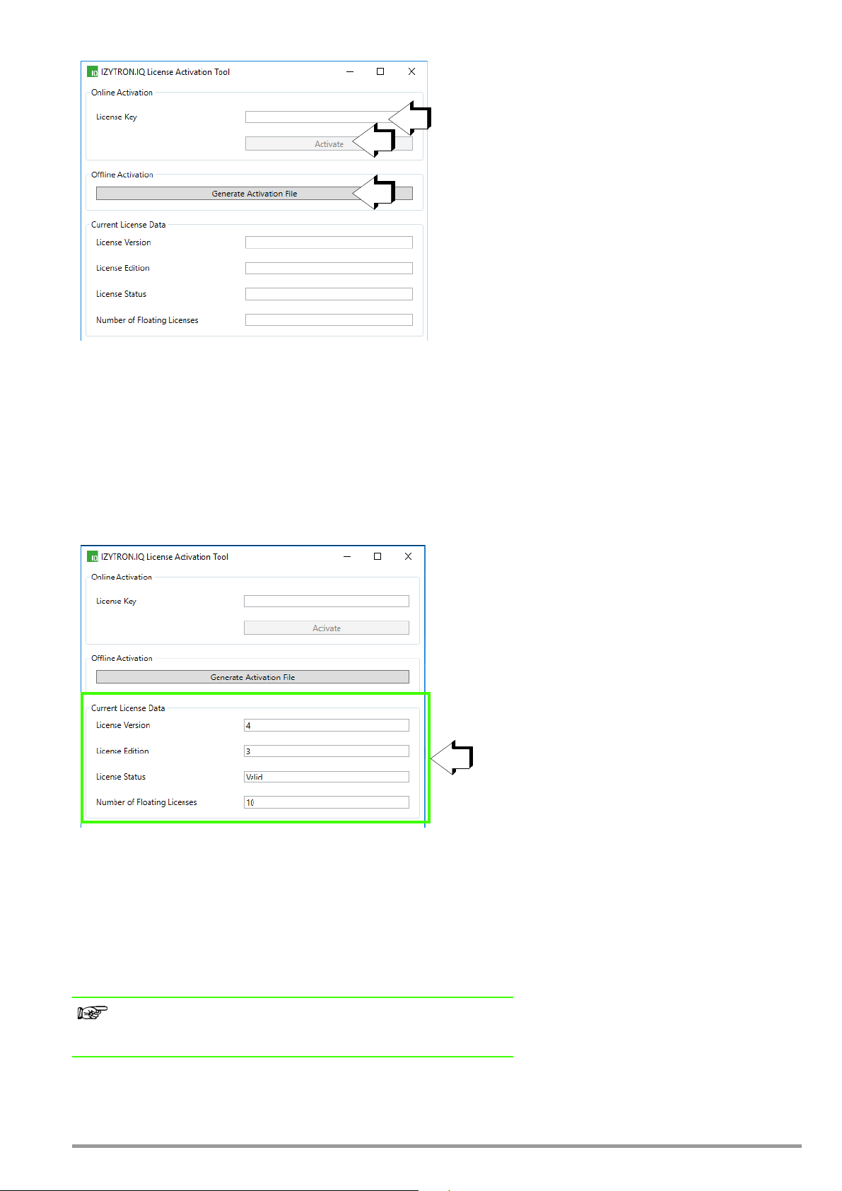
In order to activate a license for the backend application, a valid license key must be entered to the “License Key” field (1). The license
1
2
3
4
key can be found in your license certificate, which must have been issued for IZYTRONIQ Enterprise Premium. In the event that licensing
has already taken place and, for example, licensing will be extended to include one or more floating licenses, the license certificate with
the license extension must be used, because it replaces the existing license.
This license can be activated at the registration server by clicking the “Activate” button (2), assuming that the IZYTRONIQ backend server
is connected to the Internet.
If connection with the Internet is not possible, offline activation is possible as an alternative. An activation file can be generated to this
end by clicking the “Generate Activation File” button (3). Send this file to our support department via e-mail.
GMC-I Messtechnik GmbH
Product Support Hotline
Phone: +49-911-8602-0
Fax: +49-911-8602-709
e-mail: support@gossenmetrawatt.com
You will then receive a valid .lic file. The file must be saved to the following hidden directory: C:\ProgramData\Infralution\Licenses\.
Note
If a license has already been saved to the server, it’s details can be displayed under “Current License Data”.
GMC-I Messtechnik GmbH 23
Page 24

5.3 Installing the Frontend (client) for IZYTRONIQ Enterprise
IZYTRONIQ can be installed to the PC as a client. The “Network Version (Client)” option must be selected in response to the following
prompt: Standalone, Network Version (Client) or Cloud Operation.
A functioning IZYTRONIQ ENTERPRISE Backend is required to this end, whose URL is entered during the next step in accordance with
the certificate path (address to which the certificate is issued).
Example of a typical, complete entry:
https://<certificate path>/IZYTRON.IQ/
Example:
https://computer name.domain.com/IZYTRON.IQ/
The floating license is distributed by the server (ENTERPRISE Premium) and can be expanded to include offline functionality (ENTERPRISE
Ultimate), whose license code can be entered exclusively to the client’s own “Settings” menu after the client has been started.
The license activation tool for the backend may not be used to activate an IZYTRONIQ Enterprise Ultimate license!
We recommend starting the application directly after installation of the client in order to set up an administrative user.
After installation, you have the option of either starting the program directly or closing the installer.
24 GMC-I Messtechnik GmbH
Page 25

6 Licensing
A license is needed to operate IZYTRONIQ. It can be obtained online using an activation file.
6.1 Licensing BUSINESS Starter / BUSINESS Advanced / BUSINESS Professional / BUSINESS Premium / EDUCATION Professional / EDUCATION Premium
To license your IZYTRONIQ, go to reg.izytron.com and enter the registration code you received when purchasing the product, together
with your address data and your email address. Your license key will be sent to the email address you provided without delay. You must
enter this license key the first time you start IZYTRONIQ. A connection is then established with the license server for the purpose of
authentication. Your hardware (MAC address of your computer) is coupled to the license key during this process. This means that the
license can only be used with this particular hardware. Should you wish to use the license on different hardware, it is first necessary to
uninstall IZYTRONIQ on its current hardware. During this process, the license will be de-authenticated and released for use with other
hardware (new computer).
In the unlikely event that you are unable to license and authenticate the software by a one-time connection with the Internet, the licensing procedure can also be completed without an Internet connection. To do this, you will have to contact employees at GOSSEN
METRAWATT directly. Our friendly team is available to assist you on telephone: +49 911 8602-0.
6.2 Licensing ENTERPRISE Premium
To license your IZYTRONIQ, go to reg.izytron.com and enter the registration code you received when purchasing the product, together
with your address data and your email address. Your license key will be sent to the email address you provided without delay. The
license key must be entered on the server. A connection is then established with the license server for the purpose of authentication.
This means that the license can only be used with this particular hardware.
IZYTRONIQ ENTERPRISE Premium acts as the client server system and provides a network structure within this system. This structure consists of a central database server as the server component and several workstation computers as client components.
The respective administrator must install the server manually. For this purpose, the administrator will receive the installation instructions
(best practice document) describing how the MS SQL server should be configured for IZYTRONIQ. Separate license keys are not needed
for the clients in ENTERPRISE Premium. Instead you will require the necessary number of floating licenses on the server. In addition to
installing the server, you will have to install the client on each workstation computer. The database path for the server must be specified
during installation on the client. You may install an infinite number of license-free clients, but please take note that simultaneous use will
never exceed the number of floating licenses you have purchased.
In the unlikely event that you are unable to license and authenticate the software by a one-time connection with the Internet, the licensing procedure can also be completed without an Internet connection. To do this, you will have to contact employees at GOSSEN
METRAWATT directly. Our friendly team is available to assist you on telephone: +49 911 8602-0.
6.3 Licensing ENTERPRISE Ultimate
The IZYTRONIQ ENTERPRISE Ultimate licenses can only be used in combination with at least one ENTERPRISE Premium floating license. To
purchase a ENTERPRISE Ultimate license, you require a ENTERPRISE Premium license.
Each ENTERPRISE Ultimate must be licensed after installation on the mobile device (tablet, notebook).
To license your IZYTRONIQ, go to reg.izytron.com and enter the registration code you received when purchasing the product, together
with your address data and your email address. Your license key will be sent to the email address you provided without delay. You must
enter this license key the first time you start IZYTRONIQ. A connection is then established with the license server for the purpose of
authentication. Your hardware (MAC address of your computer) is coupled to the license key during this process. This means that the
license can only be used with this particular hardware. Should you wish to use the license on different hardware, it is first necessary to
uninstall IZYTRONIQ on its current hardware. During this process, the license will be de-authenticated and released for use with other
hardware (new computer).
GMC-I Messtechnik GmbH 25
Page 26
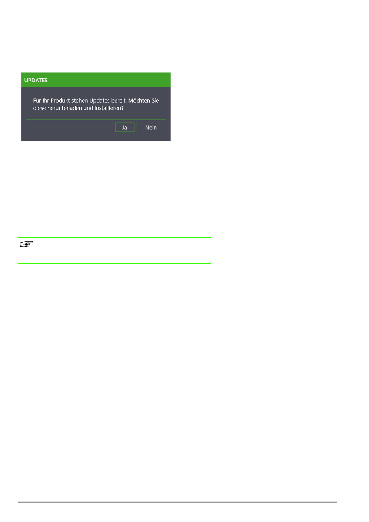
7 Update
Free updates will be available to you during the statutory warranty period.
Updates are distributed exclusively via the update service and are not installed by setup. In this regard, the software checks whether a
new version is available on the server each time it is started.
In addition, the IZYTRONIQ Global Settings contain the option to query updates manually; refer to “Global settings”.
The automatic search for updates can be disabled in the Global Settings. You have the option of concluding a maintenance contract if
you wish to receive updates beyond the statutory warranty period. Contact our sales department if you are interested.
8 Uninstallation
To uninstall IZYTRONIQ, go to the Control Panel of the operating system.
During uninstall, you can choose whether you wish to keep the local database and/or the license on your PC. They will be available for
use on an alternative PC if you release them.
Note
Only certain licenses can be released. Contact our support department
for further information.
26 GMC-I Messtechnik GmbH
Page 27
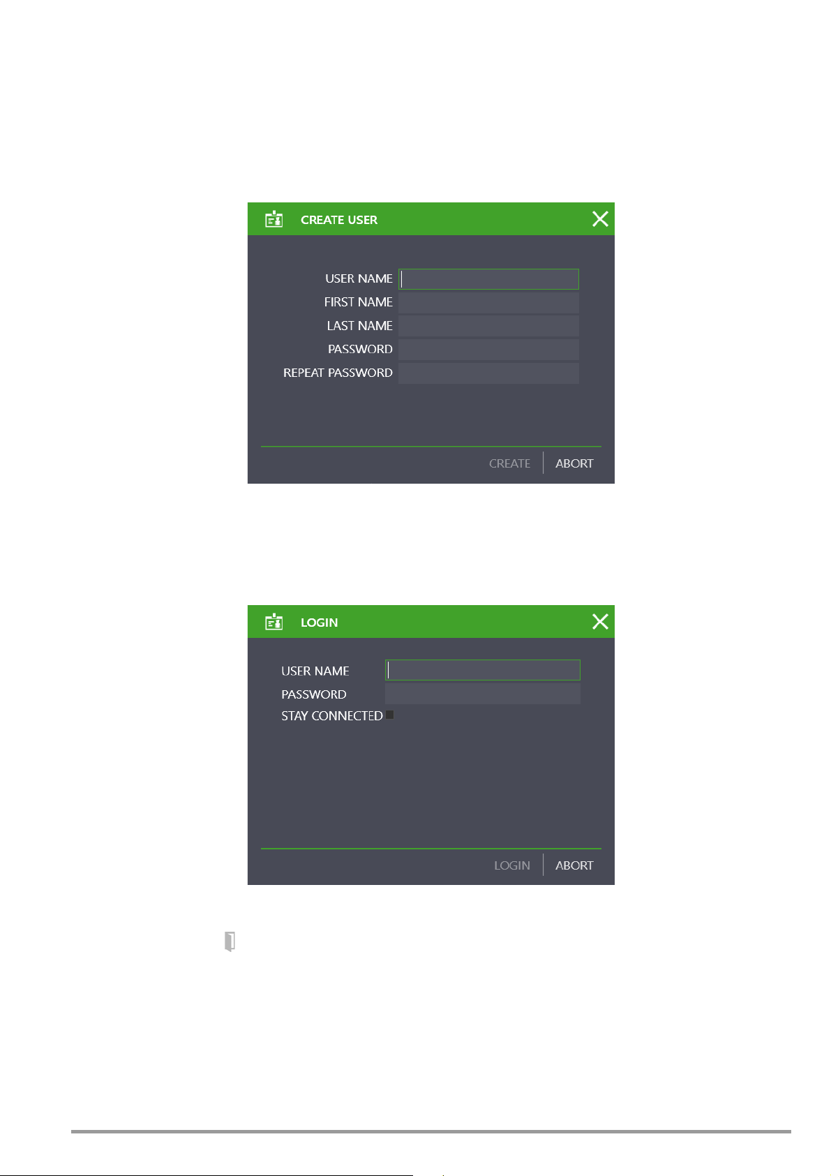
9 Login / Logout
Initial login
The first necessary step is to create a user if users have not yet been set up for the database (initial login to IZYTRONIQ). The login screen
has a heading “Create User” for this purpose.
The required information is the first and last name of the user, a personal username and a password (must be repeated). The user is
assigned the role “Admin”.
Subsequent login
Users can only access the software if they are registered in the IZYTRONIQ user management with a password.
When the software is launched after the first time, it will open a login screen to enter the user name and password.
Switching users
It is also possible to use the button in the status bar to switch users while the application is open.
Stay Connected
If you wish to remain logged in to this program at your PC, click on the entry field behind „STAY CONNECTED“ in the login window.
When restarting the program, it will then open directly without a login window appearing. You can undo this selection by opening the
„PERSONAL SETTINGS“ menu and by removing the check mark behind parameter „STAY CONNECTED“, see “Personal settings”.
Log out – close
The application has several options to close IZYTRONIQ:
GMC-I Messtechnik GmbH 27
Page 28

1. Close the IZYTRONIQ application by selecting the Close Window function in the status bar.
2. Use the symbol in the status bar:
After clicking on the symbol, you must respond to the confirmation prompt with “Yes”. Then you will see the login screen. Select
“ABORT” in this case. You close IZYTRONIQ by responding to the confirmation prompt with “Yes”.
28 GMC-I Messtechnik GmbH
Page 29

10 Basics of operation
IZYTRONIQ is operated using a number of neatly structured modules. These modules are found in the home screen and in the navigation
bar.
Portable Objects (devices and medical devices)
• Checking, registering and managing of portable devices
Stationary objects (machinery & facilities)
• Checking, registering and managing of stationary devices
User management
• Creating and managing users
Test device management
• Creating and managing test devices
Settings
• General settings for working with IZYTRONIQ
Help
• To access online help, refer to “Help”
Recycle bin
• Irreversible erasure or restoration of data moved to the recycle bin
Synchronization (ENTERPRISE Ultimate version only)
• Comparison of a server database with a local database of a PC
GMC-I Messtechnik GmbH 29
Page 30
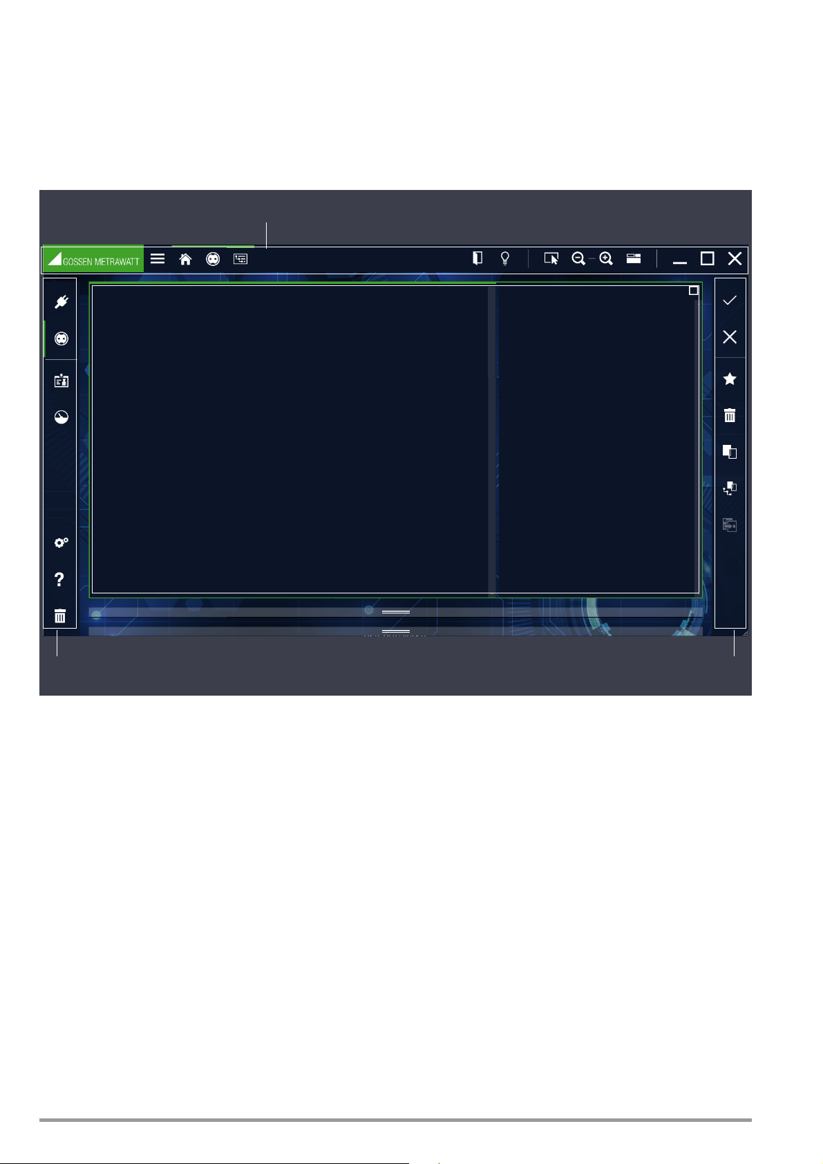
10.1 Structure of the user interface
Status bar
Navigation bar Tool ba r
Content
The status bar, navigation bar and toolbar are available to users to operate the respective interface (content).
1. Status bar (always shown)
2. Navigation bar (shown or hidden)
3. Toolbar (always shown): has context-sensitive content.
30 GMC-I Messtechnik GmbH
Page 31

10.1.1 Navigation bar
portable objects
stationary objects
User management
Test device management
Settings
Help
Recycle bin
Marking of the active module
The navigation bar is used to skip directly from one main module to the next.
The navigation bar can be shown and hidden using the symbol in the status bar.
When enabled, the navigation bar is visible in almost all control panels. Modules are opened by selecting or tapping on a module sym-
bol. A green bar in the navigation bar indicates which module is active.
GMC-I Messtechnik GmbH 31
Page 32

10.1.2 Status bar
Show or hide the navigation bar
BC navigation (active module)
The status bar contains important basic operating functions and alerts.
Breadcrumb navigation
The branch of IZYTRONIQ in which the user is currently located in shown on the left-hand side of the status bar (header). The active module is indicated by a green bar. Breadcrumb navigation enables operation without a navigation bar, which can be hidden in tablet mode
(for instance).
The other symbols have the following functions:
Show/hide the navigation bar
Logout/login:
The user is logged out and the application shows the login screen.
Quick links (from BUSINESS Professional)
Quick links make the most frequent selections in the tree structure available by mouse click. The convenient quick link function
in the status bar allows users to set up additional shortcuts. Any data can be selected there and transferred to the quick link.
The saved analysis can be executed repeatedly by double-clicking on the entry, and the results will be shown in the requested
output form.
Mouse mode:
When the user is in mouse mode, the program displays a finger to switch to touch mode. Symbols are always enlarged in touch
mode and smaller in mouse mode.
Touch mode:
A mouse pointer is shown when the user is in touch mode.
Symbols are always enlarged in touch mode and smaller in mouse mode.
Zoom factor:
Symbols to zoom in and out of the content panel.
Toggle display:
Switch the display between “Tree view and list”, “Tree view, details and list” and “Tree view and details”.
Minimize:
Users click on this symbol to minimize the window (it will only be shown as a symbol in the taskbar).
Zoom out:
Users click on this symbol to reduce the window size (it will be shown in the size selected by the user by adjusting the zoom
factor).
Maximize:
Users click on this symbol to maximize the window (it will only be shown as a symbol in the taskbar).
Close:
Users will be asked whether they want to close the application; the application is closed if the user confirms.
32 GMC-I Messtechnik GmbH
Page 33

10.1.3 Toolbar
Save changes
Cancel editing
Create new element
Delete element
Duplicate element
Copy element with sub-elements
This bar is context-sensitive and always shows the tools that are made available for the selected context. It is located on the right-hand
side of the screen.
The following sections describe the content of this bar for the individual operating windows.
GMC-I Messtechnik GmbH 33
Page 34

11 Home screen
Portable devices Test device
management
Stationary devices Graphic series of
measurements
[View valid for BUSINESS Starter and BUSINESS Advanced]
HelpSettings
User management
Recycle bin Synchronization
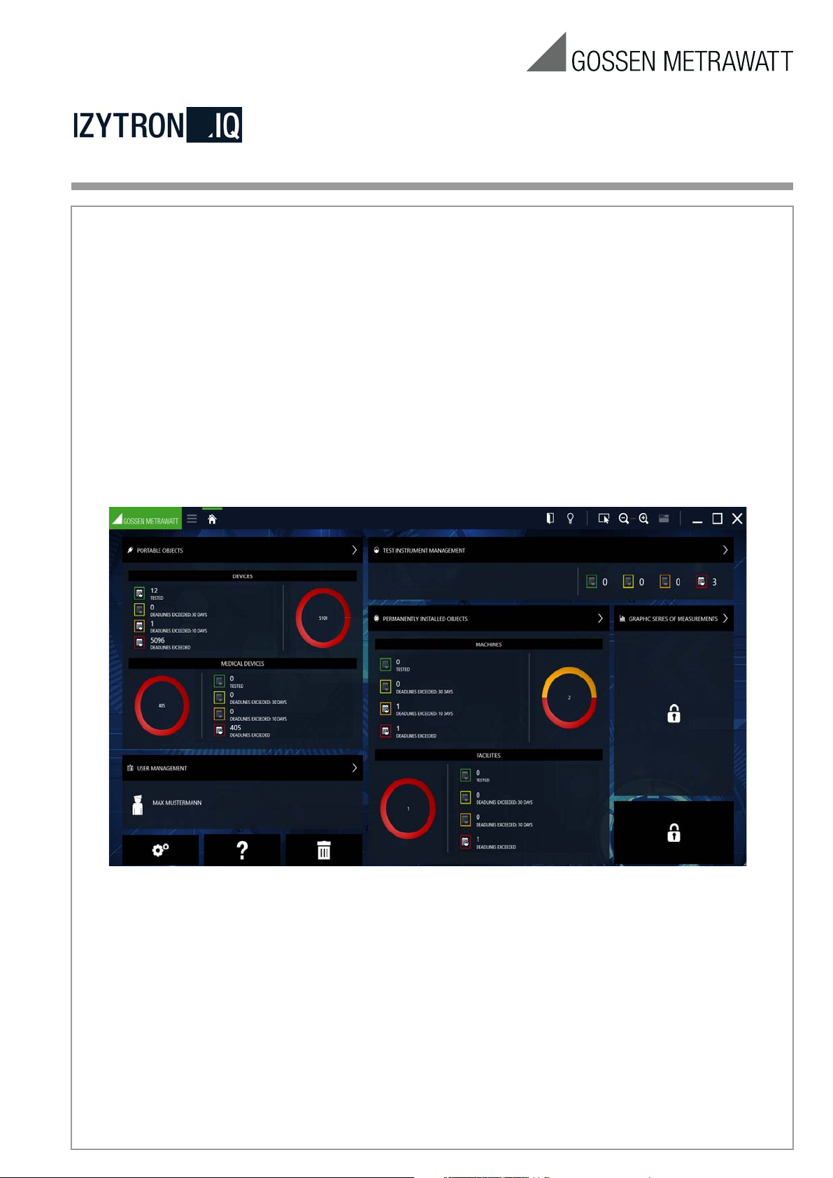
The home screen is shown once a user has logged in.
The home screen contains the elements Portable Objects, Test Device Management, User Management, Settings, Stationary Objects,
Help and the Recycling Bin. Depending on the version of IZYTRONIQ, users will see the symbol or the dashboard function; refer to
“Dashboard”.
Users access the submenus by tapping or clicking on the relevant main module.
34 GMC-I Messtechnik GmbH
Page 35

11.1 Dashboard
Portable devices Test device manage-
ment
Stationary devices
HelpSettings
User management
Graphic series of measurements
[View valid from BUSINESS Professional]
Recycle bin
Synchronization
The dashboard function is integrated in the home screen from BUSINESS Professional.
The IZYTRONIQ dashboard is an analysis tool within the home screen that assists users in more complex requirements in terms of statistics and analyses, while still providing a shortcut to the various main modules.
It enables the systematic evaluation of all tests, calibrations and deadlines and therefore ensures the necessary transparency within
your company as the foundation for your continuous process of improvement.
From version ENTERPRISE Premium, the system has the option of blocking or restricting access to the main modules by means of user
roles and rights.
Dashboard functions
Important data from several modules is also shown.
• Deadline monitoring (overdue devices, devices to be tested on short notice, devices to be tested soon, and devices outside the
escalation levels) for portable, stationary and test devices [from BUSINESS Professional]
• Connected devices for test device management
• User data of the registered user for user management
Users access the matching module segments by clicking on these areas.
GMC-I Messtechnik GmbH 35
Page 36

11.1.1 Test deadlines for objects [from BUSINESS Professional]
The dashboard function is shown as an overview diagram and pie chart in each main module.
Overview diagram
The overview shows you the evaluated number of objects belonging to this main module, grouped into 4 categories:
• Symbol in a green square: this means that all the objects listed here are within the individually defined test intervals and that all the
listed objects passed their most recent test
• Symbol in a yellow square: this means that all the objects listed here are inside the individually defined escalation time (1st escalation
level) for testing and that all the listed objects passed their most recent test
• Symbol in an orange square: this means that all the objects listed here are inside the individually defined escalation time (2nd escala-
tion level) for testing and that all the listed objects passed their most recent test
• Symbol in a RED square: this means that all the objects listed here are outside the individually defined test interval, were not tested or
did not pass their most recent test
The matching objects are shown in the filter list by selecting the symbol in the relevant colored square; refer to “Lists”.
Pie chart
The pie chart shows the percentage distribution of the aforementioned categories and the total number of listed objects.
11.1.2 Test deadlines for test devices [from BUSINESS Professional]
This dashboard function shows an overview of the calibration deadlines for test devices.
Overview diagram
The overview shows you the evaluated number of objects belonging to test device management, grouped into 4 categories:
• Symbol in a green square: this means that all the objects listed here are inside the individually defined test intervals and that all the
listed objects passed their most recent test
• Symbol in a yellow square: this means that all the objects listed here are inside the individually defined escalation time (1st escalation
level) for testing and that all the listed objects passed their most recent test
• Symbol in an orange square: this means that all the objects listed here are inside the individually defined escalation time (2nd escala-
tion level) for testing and that all the listed objects passed their most recent test
• Symbol in a RED square: this means that all the objects listed here are outside the individually defined test intervals, were not tested or
did not pass their most recent test
The matching objects are shown in the filter list by selecting the symbol in the relevant colored square; refer to “Lists”.
36 GMC-I Messtechnik GmbH
Page 37

11.1.3 Devices on the interface
This field indicates which test devices are connected. The field remains blank if no measurement or test devices are connected. Selecting the symbol opens test device management; refer to “Test device management”. When a device is connected that is not present in
the IZYTRONIQ, the system shows a message asking the user whether the test device should be saved to test device management.
11.1.4 Users
IZYTRONIQ
This field shows which person is currently logged in.
Selecting the user opens user management; refer to “User management”.
11.1.5 Graphic series of measurements
There are plans to offer an optional and paid interface for Y/t diagrams here in future.
GMC-I Messtechnik GmbH 37
Page 38

12 Main modules
IZYTRONIQ is operated using a number of neatly structured modules. These modules are found in the home screen and in the navigation
bar.
The following modules can be selected:
• Portable objects (devices and medical devices)
Checking, registering and managing of portable devices; refer to “Module for portable objects”
• Stationary objects (machinery & facilities)
Checking, registering and managing of stationary devices; refer to “Module for stationary objects”
• User management
Creating and managing users; refer to “User management”
• Test device management
Creating and managing test devices; refer to “Test device management”
• Settings
General settings for working with IZYTRONIQ; refer to “Settings”
• Help
To access online help, refer to “Help”
• Recycle bin
Irreversible erasure or restoration of data moved to the recycle bin; refer to “Recycle bin”
Synchronization (ENTERPRISE Ultimate version only)
• Comparison of a server database with a local database of a PC
38 GMC-I Messtechnik GmbH
Page 39

GMC-I Messtechnik GmbH 39
Page 40

12.1 Module for portable objects
This module is used to structure, organize and manage locations, customers and test objects.
Test sequences are managed, created and assigned to test objects here.
Tests are conducted in a dialog with measurement and test devices and then imported from the measurement and test devices. Data
can also be exported from the application to the measurement and test devices. Users have the option of comparing test results and
creating test reports.
It is also possible to create and manage report templates for test reports.
The object modules contain the following object types:
• devices
• medical devices
40 GMC-I Messtechnik GmbH
Page 41

12.1.1 Structure of the home screen
1 2 3
4 5
Selecting the object module symbol for portable devices in the home screen or in the navigation bar opens the start screen of the
object module for portable devices.
Start screen for the object module – portable objects
The following functions are available:
(1) Input, change, list: Input, change and filter objects. Management of test sequences and tests
(2) Sequences: Creating and managing test sequences
(3) Report templates: import (Word file) and manage test templates
(4) Import: Import objects
(5) Export: Export objects and sequences
GMC-I Messtechnik GmbH 41
Page 42

12.1.2 Function “Input, change, list”
This module is used to structure, organize and manage locations, customers and test objects. The sequences and tests can be managed and assigned to test objects. Test results can be compared and test reports printed out.
The module view consists of the following 3 parts:
1. Tre e view: This view consists of two sub-trees, namely the electric tree on the left and the location tree on the right.
All customers, test objects and locations – as well as their mutual relationships – can be registered, shown and managed here.
Objects can be selected here. Refer also to “The tree view:”.
2. Detailed view: All details for the selected object are shown in this view. Once the test object has been selected, the test sequences
used for this object, as well as all tests conducted on this test object, are shown in various tabs. Refer also to “The detailed view”.
3. List view – standard search: This view shows a list of all test objects located in the branch below the selected object in the tree view.
A variety of criteria can be defined to filter this list so that only the required data is shown. Objects can also be selected here. Refer
also to “The list view – standard function:” or “Lists”.
b) List view – extended search function (for large data volumes): If you work with large data volumes, it is useful to make a pre-selection
of those data which are currently relevant for you. This helps to improve system performance.
In this view, 2 index cards are shown. A selection has to be made via the first index card „SELECTION LIST“ as to which test
objects are to be displayed in the „LIST OF OBJECTS“ index card. This list, in turn, can be filtered further by means of various criteria. See also “List view – extended search function” or “Lists”.
Video „Basic operation of the three views“
42 GMC-I Messtechnik GmbH
Page 43

(1) Tree view (2) Detailed view (3a) List view – standard search; (a) Marking of active view; (b) Active sub-function
1
2
3a
a
a
b
1
2
3b
a
a
b
(1) Tree view (2) Detailed view (3b) List view – extended search function; (a) Marking of active view; (b) Active sub-function
The active view is always shown with a green border.
Within the border, the active sub-function is indicated by a bold green bar at the top.
GMC-I Messtechnik GmbH 43
Page 44

12.1.2.1 The tree view:
The tree view shows all registered test objects, customers and locations. They are displayed hierarchically as two tree structures,
namely the electric tree (on the left) and the location tree (on the right).
Selecting the node symbol opens a closed node or closes an open node.
Electric tree
This displays all customers and test objects. The objects are always assigned to a customer.
The system does not accommodate test objects that are not assigned to a customer.
Note
Although all customers are shown, regardless of the type of test object
(portable and stationary), it is only possible to access portable test
objects.
Selected test object in the e-tree
44 GMC-I Messtechnik GmbH
Page 45

Location tree
The registered locations are shown in a hierarchical form here. Test objects can be assigned to these locations, although it is not mandatory. The location tree has the 4 defined hierarchy levels of property, building, level and room. It is not mandatory to use all levels of
the hierarchy.
Selected position in the location tree
Interdependency of the tree structures
A test object can be linked to precisely one object in the location tree (although this is not necessary).
In contrast, an object in the location tree may be connected to several test objects in the electric tree. When a location is marked in the
location tree, all elements in the electric tree that are situated at this location will be marked in green.
When a test object is selected in the electric tree, its assignment to a particular location is shown by a green marking on the corre-
sponding location object.
Connection logic for the tree elements
By selecting an object in a particular tree, the tree to which it is assigned will become the active tree. As described above, this is indicated by a green border around the tree window and a bold green bar at the top. Only one object can be marked in the active tree. By
doing so, the symbol and text color of the object turn green, and the matching line is shaded in gray.
In the other tree, the matching elements are indicated by the color of the symbol and text turning green. The parent objects are always
indicated by a green symbol, while the color of the text remains white.
GMC-I Messtechnik GmbH 45
Page 46

Example for the e-tree:
The electric tree is active; the power strip (3 sockets) is selected. Therefore, the symbol and text are green and shaded gray. The loca-
tion tree now indicates that this power strip is situated in room 1.21. The parent objects Südwestpark, High-rise, 1st floor are indicated
by the green symbol, which means it is possible to identify where the power strip is located, even when the node is closed.
Example: assignment of a power strip
Example for the location tree:
The location tree is active, and room 1.22 is selected. Therefore, the symbol and text are green and shaded gray. The electric tree
shows which objects are present in this room.
Example: objects in room 1.22
46 GMC-I Messtechnik GmbH
Page 47

Functions of the toolbar – index card for tree view
Save changes
Cancel editing
Create new element:
To create a new element, the object under which this new element is to be added must be marked in advance. The marked object is
then shaded gray. After selecting , a “New Element” popup opens in which the user is offered the selection of elements that are possible for the chosen position in the tree (e.g. if it is included in the hierarchy level “building” of the location tree, it is possible to create
“levels” or “rooms”). Once the required element type has been selected, it is then necessary to define an element ID and the number of
elements to be created. The element ID can also be created automatically by a logic defined in the settings; this is mandatory to create
several elements of the same type. After creating one or several elements, the newly created element is selected automatically (the first
one if several elements are created) and the creation of a subordinate element starts. The process is only concluded when the user
explicitly closes (command CLOSE) the popup “New Element”. The newly created element/s is/are marked with a “+” until they have
been saved.
Example for a new element in the location tree
Delete element
Copy element
Copy element with sub-elements
Paste copied element (is inserted in the hierarchy below the marked element)
GMC-I Messtechnik GmbH 47
Page 48

12.1.2.1.1 Available tree elements
LOCATION TREE
In the location tree, the following elements can be created for portable objects in the hierarchy shown below.
Symbols Significance
Location tree
Property
Building
Level
Room
Creating elements is hierarchy-dependent. If the user marks an existing location in the tree, only the elements available at the selected
position in the tree are shown when a new location is created.
E-TREE
The following elements can be created in the electric tree for portable objects:
Symbols Significance
Electric tree
Customer
Device
Medical device
48 GMC-I Messtechnik GmbH
Page 49

12.1.2.2 The detailed view
The most important parameters for the object marked in the tree view (customer, device, medical device and location) are managed in
the detailed view of portable devices. The objects cannot be created or deleted here.
Important data such as the object ID, object designation and parameters for the individual objects can be created and edited in the
index cards. It is also possible to attach documents such as images, certificates and operating instructions.
When the input fields are selected, content can be added by entering text or making selections from a drop-down menu. Newly created objects in the electric tree are marked with a “+”, and edited objects with a “*”, until the changes have been saved.
Note
IZYTRONIQ does not define a limit for the number of characters in the
respective data fields, but the connected test devices themselves may
limit the number of characters. Please check the technical parameters of
the test device. A restriction of transferable data fields may apply,
depending on the connected test device. Please check the technical
parameters of the test device.
Compulsory fields.
Some fields in the input screens are compulsory.
Compulsory fields that are left blank are marked with the following symbol: .
As a result, the object cannot be saved.
The tab names and all associated displays are shown in red writing until the corresponding compulsory fields have been completed.
GMC-I Messtechnik GmbH 49
Page 50

12.1.2.2.1 Structure of the index cards
The master data consists of a differing number of index cards and contents, depending on the marked object in the tree view.
Customer: Two index cards: Customer and contacts.
Location: One index card: Master data
Device/med. Device: Four index cards: Device, technical data, test sequences and tests
Example of an index card for a device
50 GMC-I Messtechnik GmbH
Page 51

Object: Customer
Index card CUSTOMER
This can be used to add address and contact details for a selected customer:
Functions of the toolbar – index card for a customer
Save changes
Discard changes (with prompt)
Manage attachments (add, display and delete a file/photo)
Print, refer to “Print”
Index card CONTACTS
This is used to manage contacts at the respective customer.
Functions of the toolbar – index card for CONTACTS
Save changes
Discard changes (with prompt)
Create new contact
Delete contact
Manage attachments (add, display and delete a file/photo)
Print, refer to “Print”
This index card is a list, so the functions of the list view will apply; the list symbols will be active in the toolbar as well; refer to “Lists”.
GMC-I Messtechnik GmbH 51
Page 52

Object: Location
Index card Location
The address and building data are entered here.
Locations are divided into the four hierarchies of property, building, level and room.
The following data can be added, depending on the main object:
Property: Address data, comments
Building: Address and architectural data, comments
Level: ID and designation, comments
Room: ID and designation, comments
Functions of the toolbar – index card for a Location
Save changes
Discard changes (with prompt)
Manage attachments (add, display and delete a file/photo)
Print, refer to “Print”
52 GMC-I Messtechnik GmbH
Page 53

Object: Device
The manufacturer, test and technical data are added to the device object. The test sequences used to test the device, as well as the
data for the listed tests, are also saved.
Index card DEVICE and TECHNICAL DATA
Important data such as the object ID, object designation and parameters for the individual objects can be created and edited in the
index cards. It is also possible to attach documents such as images, certificates and operating instructions.
When the input fields are clicked on, content can be added by entering text or making selections from a drop-down menu. Newly created objects in the electric tree are marked with a “+”, and edited objects with a “*”, until the changes have been saved.
Functions of the toolbar – index card for a Device/Technical Data
Save changes
Discard changes (with prompt)
Manage attachments (add, display and delete a file/photo)
Print, refer to “Print”
Video „Creation of devices“
GMC-I Messtechnik GmbH 53
Page 54

Index card TEST SEQUENCE
The test sequence index card is used to assign text sequences to the selected object.
Several test sequences can be assigned to one object.
The view of assigned test sequences is shown in a list. A marked checkbox in the second column (Standard) indicates the test
sequence with which the object is to be tested.
The test sequences themselves are managed in a parent sequence pool; refer to “Sequences function”.
Note
Deleting only removes the link, but not the sequence. The sequence
remains present in the sequence pool.
Functions of the toolbar – index card for a TEST SEQUENCE
Save changes
Discard changes (with prompt)
Show sequence details (if the user is in the sequence list)
Show sequence list (if the user is in the sequence detailed view)
Add sequences from the sequence pool
Delete sequence assignment; the sequence itself remains present in the sequence pool.
Manage attachments (add, display and delete a file/photo)
Print, refer to “Print”
This index card is a list, so the functions of the list view will apply; the list symbols will be active in the toolbar as well; refer to “Lists”.
Sequence steps
Users can show the details (individual steps) of a sequence by double-clicking on the sequence or by marking the sequence and then
selecting the symbol . This opens a list of sequence steps, which is shown instead of the sequence list.
Users return to the original screen by selecting the symbol .
Index card: Tests
The index card for tests is used to manage and create tests for the selected object. The tests listed here are created in a variety of
ways. Selecting the tool symbol opens the popup “Add Test”, which offers the following options:
54 GMC-I Messtechnik GmbH
Page 55

► REMOTE: the application controls the sequence process (refer to “Automatic process control for a test – remote function”) Here you
can execute, control and analyze test sequences in IZYTRONIQ. You can conduct remote testing with a variety of test devices and
then analyze the results. Attachments such as circuit diagrams, drawings, instruction photos etc. can also be shown. Measurements can be conducted and reported using any test devices; refer to “Document management”.
► PUSH/PRINT: input at the push of a button on the test device (refer to “Push/Print – first steps”):
The push/print function allows users to send test results directly to the selected test object in the IZYTRONIQ and to save them there
in the Tests tab at the push of a button on the test device.
► Manual input [from BUSINESS Professional]
This function allows tests to be conducted with any test devices that are not connected to IZYTRONIQ. It is also possible to create
tests that do not require a test device, e.g. stating a number.
Users select the function “Manual Input” and then click on “ADD” to open the window “MANUAL INPUT”.
They enter a test name and the test device used in the upper content section. The tester and the date are added automatically.
Take n o t e: Only test devices registered in test device management are eligible for selection.
Manual tests can be created in each row in the lower content section. To do this, users select the function
“ADD TEST STEP” in
the toolbar. This is used to document current tests, whereby the following fields can be completed. Only the field “Test step” is
compulsory.
No. Sequential number of the test step (automatic)
Step type Manual (automatic)
Test device Test device used (automatic)
Test step Test step, e.g. measurement
Min. Minimum value
Max. Maximum value
Result Result value
Analysis Analysis
Attachment Shows any documents that are added.
The manual measurement is completed by saving the entries, and the screen returns to the index card “TESTS”. The created
measurement is now shown here.
Video „Manual input of measured values“
GMC-I Messtechnik GmbH 55
Page 56

► Create container, grouping of available tests
This function is used to group several tests for the selected object in one container. A joint report of these tests can therefore be
created. The individual tests include the name of the responsible tester; the creator is responsible for the container.
The first step in creating a container is to mark the tests that will be included in the container. Afterwards, the user selects “CREATE
TEST CONTAINER” in the toolbar. Clicking on “ADD” opens an input screen to create the container name and to add the tester responsible for the container. Clicking again on “ADD” creates the container, and the program returns to the index card for tests.
Video „Creation of container“
Functions of the toolbar – index card for a TEST
Save changes
Discard changes (with prompt)
Show tests/container details (if the user is in the matching tests)
Skip to one level higher (if the user is in the test/container details screen)
Creating tests according to the methods outlined above
Delete tests and containers
Create containers
Add tests to the container
Cancel the container
Compare tests:
Two or more similar tests can be compared. Users click on the symbol and then mark the tests they wish to compare. After
confirming, the results are shown as a table.
Manage attachments (add, display and delete a file/photo)
Print, refer to “Print”
Print reports
This index card is a list, so it is subject to the functions of the list view. The list symbols are also enabled in the toolbar; refer to “Lists”.
Test steps
Users can show the details (individual steps) of a test by double-clicking on the test or by marking the test and then selecting the symbol . This opens a list of test steps, which is shown instead of the test list.
Users return to the original screen by selecting the symbol .
Video „Test comparison“
56 GMC-I Messtechnik GmbH
Page 57

12.1.2.3 List views
Two list views are available which differ with regard to the type of selection and search function:
– standard function
– extended search function
For large data volumes we recommend the extended sarch function which conforms to the default setting.
The respective selection has to be made in the following menu path:
SETTINGS > PERSONAL SETTINGS > GENERAL SETTINGS >
Parameter ACTIVATE EXTENDED SEARCH FUNCTION (FOR LARGE DATA VOLUMES)
The extended search function is active when the appropriate tick mark is set.
The list view – standard function:
The list view shows all objects located in the tree view hierarchy below the selected element. This means, for example, that all test
objects for one customer or all test objects located in the room can be listed. Here, only one element can be selected in the tree view.
The number of currently listed elements is shown in the window at the bottom right.
Functions of the toolbar
Save changes
Cancel editing
Delete objects
Print, refer to “Print”
Print reports
Multi-assistant (from BUSINESS Professional); refer to “Multi-assistant (from BUSINESS Professional)”
This index card is a list, so it is subject to the functions of the list view. The list symbols are also enabled in the toolbar; refer to “Lists”.
GMC-I Messtechnik GmbH 57
Page 58

List view – extended search function
This list view is useful if you work with large data volumes. In order to use it, you have to make a pre-selection of the data which are
currently relevant for you.
In this view, 2 index cards are shown. A selection has to be made via the first index card „SELECTION LIST“ as to which test objects
are to be displayed in the „LIST OF OBJECTS“ index card. Open the extended search function afterwards by pressing the key . A
window pops up showing a progress bar. The list, which is subsequently created, is opened in the „LIST OF OBJECTS“ index card and
can be filtered further by means of various filter criteria.
Index card SELECTION LIST
Functions of the toolbar
Save changes
Cancel editing
Create list
Delete all selection criteria
This index card is a list, so it is subject to the functions of the list view. The list symbols are also enabled in the toolbar; refer to “Lists”.
58 GMC-I Messtechnik GmbH
Page 59

LIST OF OBJECTS Index card
Functions of the toolbar
Save changes
Cancel editing
Delete objects
Print, refer to “Print”
Print reports
Multi-assistant (from BUSINESS Professional); refer to “Multi-assistant (from BUSINESS Professional)”
This index card is a list, so it is subject to the functions of the list view. The list symbols are also enabled in the toolbar; refer to “Lists”.
GMC-I Messtechnik GmbH 59
Page 60

12.1.3 Sequences function
Miscellaneous
Sequences can be assigned to each electric test object. A sequence consists of individual test steps in a certain order. The use of test
sequences is advisable if a set of freely programmed test steps will be performed one after the other.
Visual inspections, instructions, checks and individual measurements can be grouped to create automatic test sequences.
The sequences are specific to a test device and are saved to a sequence pool. They are transferred to the matching test device when
needed.
A distinction is always made between the following types of sequence:
Test device sequences
These are test sequences that were created for a specific test device type, e.g. PROFITEST or SECUTEST.
Test device sequences are easy to program in the sequence editor and can be transferred to the test device later on.
Note
Fixed SECUTEST sequences: SECUTEST has configurable auto-sequences
that cannot be transferred bi-directionally. In addition, the test device
sequences described here can be transferred to the SECUTEST. Here,
only the transferable sequences can be edited and managed in
sequence management.
IZY sequences
The sequences can only be executed in the IZYTRONIQ. They may contain test steps from device sequences, but also come with many
other functions. For instance, manual measurement input, push/print tests, remote measurements, instructions and visual inspections
can be integrated as well. Helpful images can also be saved for each test, which are then shown to the user step-by-step during the
test. Sequences that have already been programmed can be used to cascade an IZY sequence; additionally, measurement steps for
various test devices can also be programmed within one sequence. When a measurement step is programmed for a remote test, it
then controls the matching test device, whereby the test device merely transfers the measured data. Display and control are managed
in the IZYTRONIQ.
Note
Factory sequences
These are assigned test sequences whose process and parameters cannot be changed and that are configured as factory settings. GMC-I
Messtechnik GmbH can make the sequences available as test device
sequences and as IZY sequences.
60 GMC-I Messtechnik GmbH
Page 61

12.1.3.1 Structure and operation of sequence management
1
2
The overview/index card for sequence management is divided into two parts, namely the list and detailed view.
List view
The upper window shows the list of sequences in the sequence pool (in the sequence storage).
Detailed view
The lower window shows the individual test steps for the sequence marked in the upper window.
Sequence view: (1) List view, (2) Detailed view
The respective view has a green border, and the active part of the view is marked by a bold green bar in the top left part of the view.
The toolbar only shows the symbols that are valid and can be activated for the selected view.
Toolbar functions in the list view
Save changes
Cancel editing
Add new sequences: The sequence editor is launched (refer to “Sequence editor”).
This enables the creation of a new sequence, which is added to the sequence pool (sequence storage).
Edit sequence:
The marked sequence can be edited in the sequence editor.
Duplicate sequence:
This command copies the marked sequence. The name of the sequence is adopted, with the suffix “Copy”.
Delete sequence:
This deletes the sequence. If the sequence has already been assigned to one or several objects, all assignments must be
deleted before the sequence is deleted.
Manage attachments (add, display and delete a file/photo)
This index card is a list, so it is subject to the functions of the list view. The list symbols are also enabled in the toolbar; refer to “Lists”.
GMC-I Messtechnik GmbH 61
Page 62

12.1.4 Data import function (from the test device)
The import function is used to synchronize data from a test device or a file with the database in IZYTRONIQ.
The function is found under “IMPORT” in the menu “PORTABLE OBJECTS”. Selecting this function opens the import assis-
tant.
The import assistant asks whether the data should be imported from a connected test device or a file (XML or CSV).
– FROM THE TEST DEVICE: here you can choose between connected devices.
OBJECTS AND TESTS are selected for import in the default setting.
– FROM A FILE: Touch the field “SELECT” to select the file to which you wish to import the data. You can also select the file format in
the open Windows Explorer panel. A customer from the database is specified if the file does not contain a customer.
To start import, select IMPORT EVERYTHING or SELECT IN IMPORT PREVIEW.
– Import takes place automatically if you select IMPORT EVERYTHING and then click on IMPORT.
– SELECT IN IMPORT PREVIEW
objects are then imported to the IZYTRONIQ database by selecting the function .
A message is shown confirming successful import and any transmission errors.
The conflict manager is activated when there are conflicts between existing and imported data that cannot be resolved automatically.
Video „File import via preview“
initially shows the data in the IMPORT PREVIEW. The data can then be selected and edited. The
62 GMC-I Messtechnik GmbH
Page 63

12.1.4.1 The conflict manager
Show details
Warning symbol
1
Hide details
Where there are conflicts during import that prevent transfer of the objects, these objects are not simply discarded. Instead, an attempt
is made to resolve these conflicts manually. To do this, the relevant objects are copied to a separate folder/table. At the same time, a
warning symbol is shown in the status bar and the entries are marked in red.
Conflicts are edited here. There is a description for each conflict. The details for the conflict objects are shown (1) by selecting the detail
symbol (+).
GMC-I Messtechnik GmbH 63
Page 64

Users are shown possible methods to resolve the conflict by clicking several times on the handshake symbol (2): Ignore, merge or new.
2
3
These depend on the specific conflict. Alternatively, users can click on the column “Resolution” to open a pull-down menu with a selection of possible solutions.
The red marking is hidden when a method is selected. The conflict is resolved by saving the changes. The resolved entry is then no
longer shown in the conflict manager, and the corresponding object is integrated in the main database. The conflict manager is closed
once all conflicts in the list have been resolved.
Resolution options
Designation Description
Ignore Data import will be ignored.
Update with source ID (of the imported object). All data stored in IZYTRONIQ for this object will be overwritten.
Update with target ID (of the existing object) All data stored in IZYTRONIQ for this object will be overwritten, apart from the ID.
Merge The object’s master data will be synchronized.
New The object will be imported and a new ID will be issued.
...
64 GMC-I Messtechnik GmbH
Page 65

Functions of the toolbar
Resolution of the conflict
Selection of the solution method
This index card is a list, so it is subject to the functions of the list view. The list symbols are also enabled in the toolbar; refer to “Lists”.
Video „Conflict manager method“
GMC-I Messtechnik GmbH 65
Page 66

12.1.5 Data export function to the test device
The export function is used to transfer data to a test device or a file. The function is found under “EXPORT” in the menu “PORTABLE OBJECTS” . Selecting this function opens the export assistant.
The export assistant asks whether the data should be exported to a connected test device or an XML or CSV file.
– TO THE TEST DEVICE: here you can choose between connected devices.
You can select OBJECTS and/or SEQUENCES.
– TO AN XML/CSV FILE: Touch the field “SAVE AS” to select the file in which you wish to save the data.
Take not e !
Export deletes all data on the connected test device. You are therefore
shown a warning before export.
Selecting EXPORT starts the EXPORT FILTER.
Export filter
The export filter consists of two filter menus:
• EXPORT FILTER OBJECTS
• EXPORT SEQUENCES
When more than one filter menu is selected, the user switches between the views using the buttons “NEXT”, i.e. “BACK”. By
selecting the “EXPORT” button in the toolbar, the selected data and the corresponding customers and locations are transferred to
the connected test device. The current operation is shown during export. Users are shown a message once all data has been transferred successfully.
66 GMC-I Messtechnik GmbH
Page 67

Select and filter objects
The export filter OBJECTS consists of a two-part view. The upper half contains the two tree views, while the lower half shows a list of
objects selected. Activating the checkboxes in front of the elements in the tree views is used to make a preselection based on customers and locations. Here, users can select the objects in the electric tree that they wish to transfer, which they then narrow down by
selecting locations in the location tree. Additional filters in the lower list can be applied to the element selected in this way (refer to
“Lists”).
Select and filter sequences
The sequences for export can be selected and filtered here.
GMC-I Messtechnik GmbH 67
Page 68

12.1.6 Test templates function
The test templates are used to document, e.g. tests, or as acceptance or handover records, among other things. They use variable
data from the selected measurements, combined with object-related data (e.g. customer data). Report templates either comply with
statutory requirements or standards, or have been, i.e. are prepared to standardize documentation. IZYTRONIQ contains factory-configured, standard records that can neither be edited nor deleted.
You can create new templates or copy and edit existing templates.
From version BUSINESS Advanced and above, a company logo or a scanned signature can be integrated in the report templates. They
are stored in setup under global or personal settings; refer to “Global settings” and “Personal settings”.
The templates are created in MS Word, and placeholders can be used to arrange the test data in any way; refer to “Editing report tem-
plates”.
You will find reports management for portable objects under “REPORT TEMPLATES” in the “PORTABLE OBJECTS” menu.
Selection list of report templates
All available report templates are shown in record management.
If users wish to print out a test record, the report templates associated with the respective object type (device, medical device) are
shown.
A record must be created in advance using MS Word in order to add a new record. New records are included in the list using the button “ADD REPORT TEMPLATE”. Clicking on this symbol opens a system-specific menu to open Word documents. Users then
select their chosen report template and confirm the choice to add a new entry in the management table. To save the new report template, users must select the device type for which the report template will apply and then add the name of the report template.
68 GMC-I Messtechnik GmbH
Page 69

Functions of the toolbar
Save changes
Cancel editing
Save report template as an MS Word file
Open the report template as an MS Word file
Add a new report template
Duplicate the report template:
This command copies the marked report template. The name of the report template is adopted, with the suffix “Copy”.
Delete the report template:
This deletes the sequence. If the sequence has already been assigned to one or several objects, all assignments must be
deleted before the sequence is deleted.
This index card is a list, so it is subject to the functions of the list view. The list symbols are also enabled in the toolbar; refer to “Lists”.
GMC-I Messtechnik GmbH 69
Page 70

12.2 Module for stationary objects
This module is used to structure, organize and manage locations, customers and test objects.
In addition, test sequences are managed, created and assigned to test objects here.
Tests are conducted in a dialog with measurement and test devices and then imported from the measurement and test devices. Data
can also be exported from the application to the measurement and test devices. Users have the option of comparing test results and
creating test reports.
It is also possible to create and manage report templates for test reports.
The object modules contain two main categories:
• Facility
• Machine
70 GMC-I Messtechnik GmbH
Page 71

12.2.1 Structure of the home screen
1 2 3
4 5
Selecting the object module symbol for stationary devices in the home screen or in the navigation bar opens the start screen of the
object module for stationary devices.
Start screen - stationary objects
The following functions are available:
(1) Input, change, list: Input, change and filter objects. Management of test sequences and tests
(2) Sequences: Creating and managing test sequences
(3) Report templates: import (Word file) and manage test templates
(4) Import: Import objects
(5) Export: Export objects and sequences
GMC-I Messtechnik GmbH 71
Page 72

12.2.2 Function “Input, change, list”
This module is used to structure, organize and manage locations, customers and test objects. The sequences and tests can be managed and assigned to test objects. Test results can be compared and test reports printed out.
The module view consists of the following 3 parts:
4. Tre e view: This view consists of two sub-trees, namely the electric tree on the left and the location tree on the right.
All customers, test objects and locations – as well as their mutual relationships – can be registered, shown and managed here.
Objects can be selected here. Refer also to “Tree view”.
5. Detailed view: All details for the selected object are shown in this view. Once the test object has been selected, the test sequences
used for this object, as well as all tests conducted on this test object, are shown in various tabs. Refer also to “Detailed view:”.
6. a) List view: This view shows a list of all test objects located in the branch below the selected object in the tree view. A variety of criteria can be defined to filter this list so that only the required data is shown. Objects can also be selected here. Refer also to “List
view – Standard function” or “Lists”.
b) List view – extended sarch function (for large data volumes): If you work with large data volumes, it is useful to make a pre-selection of
those data which are currently relevant for you. This helps to improve system performance.
In this view, 2 index cards are shown. A selection has to be made via the first index card „SELECTION LIST“ as to which test
objects are to be displayed in the „LIST OF OBJECTS“ index card. This list, in turn, can be filtered further by means of various criteria. See also “List view – extended search function” or “Lists”.
Video „Basic operation of the three views“ using the example of portable objects
72 GMC-I Messtechnik GmbH
Page 73

1
2
3a
a
a
b
1
2
3b
a
a
b
(1) Tree view (2) Detailed view (3a) List view – standard search; (a) Marking of active view; (b) Active sub-function
(1) Tree view (2) Detailed view (3b) List view – extended search; (a) Marking of active view; (b) Active sub-function
The active view is always shown with a green border.
Within the border, the active sub-function is indicated by a bold green bar at the top.
GMC-I Messtechnik GmbH 73
Page 74

12.2.2.1 Tree view
The tree view shows all registered test objects, customers and locations. They are displayed hierarchically as two tree structures,
namely the electric tree (on the left) and the location tree (on the right).
Selecting the node symbol opens a closed node or closes an open node.
Electric tree
This displays all customers and test objects. The objects are always assigned to a customer.
The system does not accommodate test objects that are not assigned to a customer.
Note
Although all customers are shown, regardless of the type of test object
(portable and stationary), it is only possible to access stationary test
objects.
Selected test object in the e-tree
74 GMC-I Messtechnik GmbH
Page 75

Location tree
The registered locations are shown in a hierarchical form here. Test objects can be assigned to these locations, although it is not mandatory. The location tree has the 4 defined hierarchy levels of property, building, level and room. It is not mandatory to use all levels of
the hierarchy.
Image 1Tree view: Location tree is selected
Interdependency of the tree structures
A test object can be linked to precisely one object in the location tree (although this is not necessary).
In contrast, an object in the location tree may be connected to several test objects in the electric tree. When a location is marked in the
location tree, all elements in the electric tree that are situated at this location will be marked in green.
When a test object is selected in the electric tree, its assignment to a particular location is shown by a green marking on the corresponding location object.
Connection logic for the tree elements
By selecting an object in a particular tree, the tree to which it is assigned will become the active tree. As described above, this is indicated by a green border around the tree window and a bold green bar at the top. Only one object can be marked in the active tree. By
doing so, the symbol and text color of the object turn green, and the matching line is shaded in gray.
In the other tree, the matching elements are indicated by the color of the symbol and text turning green. The parent objects are always
indicated by a green symbol, while the color of the text remains white.
GMC-I Messtechnik GmbH 75
Page 76

Example for the e-tree:
The electric tree is active; the socket 01.19 is selected. Therefore, the symbol and text are green and shaded gray. The location tree
now indicates that this socket is situated in room 1.23. The parent objects Südwestpark, High-rise, 1st floor are indicated by the green
symbol, which means it is possible to identify where the socket is located, even when the node is closed.
Example: assignment of the socket
Example for the location tree:
The location tree is active, and room 1.23 is selected Therefore, the symbol and text are green and shaded gray. The electric tree indi-
cates that only the socket 01.19 is located in this room. The parent objects Customer Gossen Metrawatt, House installation, Main distributor 1, RCD01.00, F01.01 are indicated by the green symbol, which means it is possible to identify that an object belonging to this
parent node is located in the selected room, even when the node is minimized.
Example: objects in room 1.23
76 GMC-I Messtechnik GmbH
Page 77

Functions of the toolbar in the tree view
Save changes
Cancel editing
Create new element:
To create a new element, the object under which this new element is to be added must be marked in advance. The marked object is
then shaded gray. After selecting , a “New Element” popup opens in which the user is offered the selection of elements that are possible for the chosen position in the tree (e.g., if it is included in the hierarchy level “building” of the location tree, it is possible to create
“levels” or “rooms”). Once the required element type has been selected, it is then necessary to define an element ID and the number of
elements to be created. The element ID can also be created automatically by a logic defined in the settings; this is mandatory to create
several elements of the same type. After creating one or several elements, the newly created element is selected automatically (the first
one if several elements are created) and the creation of a subordinate element starts. The process is only concluded when the user
explicitly closes (command CLOSE) the popup “New Element”. The newly created element/s is/are marked with a “+” until they have
been saved.
Example for a new element in the location tree
Delete element
Copy element
Copy element with sub-elements
Paste copied element (is inserted in the hierarchy below the marked element)
GMC-I Messtechnik GmbH 77
Page 78

12.2.2.1.1 Available tree elements
LOCATION TREE
In the location tree, the following elements can be created for stationary objects in the hierarchy shown below.
Symbols Significance
Location tree
Property
Building
Level
Room
Creating elements is hierarchy-dependent. If the user marks an existing location in the tree, only the elements available at the selected
position in the tree are shown when a new location is created.
E-TREE
The following elements can be created in the electric tree for stationary objects:
Symbols Significance
Electric tree – stationary objects
Electric facility
Machine
Distributor
Electric circuit
RCD
RCM
IMD
Equipment
Equipotential bonding rail
Equipotential bonding conductor
Ground connector
Measurement point
78 GMC-I Messtechnik GmbH
Page 79

12.2.2.2 Detailed view:
The most important parameters for the object marked in the tree view (customer, device, machine, distributor, electric circuit, RCD,
RMD, IMD, equipment, equipotential bonding rail, equipotential bonding conductor, ground connector, measurement point and location) are managed in the detailed view of stationary devices. The objects cannot be created or deleted here.
Important data such as the object ID, object designation and parameters for the individual objects can be created and edited in the
index cards. It is also possible to attach documents such as images, certificates and operating instructions.
When the input fields are clicked on, content can be added by entering text or making selections from a drop-down menu. Newly created objects in the electric tree are marked with a “+”, and edited objects with a “*”, until the changes have been saved.
Note
IZYTRONIQ does not define a limit for the number of characters in the
respective data fields, but the connected test devices themselves may
limit the number of characters. Please check the technical parameters of
the test device. A restriction of transferable data fields may apply,
depending on the connected test device. Please check the technical
parameters of the test device.
Compulsory fields
Some fields in the input screens are compulsory.
Compulsory fields that are left blank are marked with the following symbol: .
As a result, the object cannot be saved.
The tab names and all associated displays are shown in red writing until the corresponding compulsory fields have been completed.
GMC-I Messtechnik GmbH 79
Page 80

12.2.2.2.1 Structure of the index cards
The master data consists of a differing number of index cards and contents, depending on the marked object in the tree view.
Customer: Two index cards: Customer and contacts.
Location: One index card: Master data
Test objects Three index cards: Element, test sequence and tests. Additionally, the index card “Technical Data” for the test
object facility/machinery.
Example of the index card for a facility
80 GMC-I Messtechnik GmbH
Page 81

Object: Customer
Index card CUSTOMER
This can be used to add address and contact details for a selected customer:
Functions of the toolbar – index card for a CUSTOMER
Save changes
Discard changes (with prompt)
Manage attachments (add, display and delete a file/photo)
Print, refer to “Print”
Index card CONTACTS
This is used to manage contacts at the respective customer.
Functions of the toolbar – index card for CONTACTS
Save changes
Discard changes (with prompt)
Create new contact
Delete contact
Manage attachments (add, display and delete a file/photo)
Print, refer to “Print”
This index card is a list, so the functions of the list view will apply; the list symbols will be active in the toolbar as well; refer to “Lists”.
GMC-I Messtechnik GmbH 81
Page 82

Object: Location
Index card Location
The address and building data are entered here.
Locations are divided into the four hierarchies of property, building, level and room.
The following data can be added, depending on the main object:
Property: Address data, comments
Building: Address and architectural data, comments
Level: ID and designation, comments
Room: ID and designation, comments
Functions of the toolbar – index card for a Location
Save changes
Discard changes (with prompt)
Manage attachments (add, display and delete a file/photo)
Print, refer to “Print”
82 GMC-I Messtechnik GmbH
Page 83

Test object
The test object is structured into three, i.e. four index cards (TEST OBJECT, TEST SEQUENCE, TESTS and (for facilities, i.e. machinery)
also the TECHNICAL DATA).
Index card TEST OBJECT <Name>
Important data such as the object ID, object designation and parameters for the individual objects can be created and edited in the
index cards. It is also possible to attach documents such as images, certificates and operating instructions.
When the input fields are clicked on, content can be added by entering text or making selections from a drop-down menu. Newly created objects in the electric tree are marked with a “+”, and edited objects with a “*”, until the changes have been saved.
Functions of the toolbar – index card TEST OBJECT
Save changes
Discard changes (with prompt)
Manage attachments (add, display and delete a file/photo)
Print, refer to “Print”
Index card TECHNICAL DATA (only for facilities and machinery)
An additional index card is necessary, as test objects of this type require extensive data. The data to describe the facility can be
entered here.
Functions of the toolbar – index card TECHNICAL DATA
Save changes
Discard changes (with prompt)
Manage attachments (add, display and delete a file/photo)
Print, refer to “Print”
Video „Creation of machines and systems“
GMC-I Messtechnik GmbH 83
Page 84

Index card TEST SEQUENCE
The test sequence index card is used to assign text sequences to the selected object.
Several test sequences can be assigned to one object.
The view of assigned test sequences is shown in a list. A marked checkbox in the column STANDARD indicates the test sequence with
which the object is to be tested.
The test sequences themselves are managed in a parent sequence pool; refer to “Sequences function”.
Note
Deleting only removes the link, but not the sequence. The sequence
remains present in the sequence pool.
Sequence steps
Users can show the details (individual steps) of a sequence by double-clicking on the sequence or by marking the sequence and then
selecting the symbol . This opens a list of sequence steps, which is shown instead of the sequence list.
Users return to the original screen by selecting the symbol .
Functions of the toolbar – index card for a TEST SEQUENCE
Save changes
Discard changes (with prompt)
Show sequence details (if the user is in the sequence list)
Show sequence list (if the user is in the sequence detailed view)
Add sequences from the sequence pool
Delete sequence assignment; the sequence itself remains present in the sequence pool.
Manage attachments (add, display and delete a file/photo)
Print, refer to “Print”
This index card is a list, so the functions of the list view will apply; the list symbols will be active in the toolbar as well; refer to “Lists”.
Index card TESTS
The index card for tests is used to manage and create tests for the selected object. The view of assigned tests conducted is shown in
a list.
The tests listed here are created in a variety of ways:
– Import of measurements from the test device or from a file
– Direct execution of tests by different methods
Test details – show elements with lower hierarchy
Users can show the details of a test by double-clicking on the test or by marking the test and then selecting the symbol . This
opens the detailed view for the test. If a “+” symbol is placed in front of the line, additional information is available by selecting the symbol or by double-click, whereby users can switch between MEASURED VALUES and PARAMETERS.
Users return to the original screen by selecting the symbol .
Direct execution of tests
Selecting the tool symbol opens the popup “Add Test”, which offers the following options:
84 GMC-I Messtechnik GmbH
Page 85

ADD TEST
► REMOTE:
The application controls the sequence process (refer to “Automatic process control for a test – remote function”)
Here you can execute, control and analyze test sequences in IZYTRONIQ. You can conduct remote testing with a variety of test devices and then analyze the results. Attachments such as circuit diagrams, drawings, instruction photos etc. can also be shown.
Measurements can be conducted and reported using any test devices; refer to “Document management”.
► PUSH/PRINT:
Input at the push of a button on the test device (refer to “Push/Print – first steps”):
The push/print function allows users to send measured results directly to the selected test object in the IZYTRONIQ and to save them
there in the Tests tab at the push of a button on the test device.
► Manual input:
This function allows tests to be conducted with any test devices that are not connected to IZYTRONIQ. It is also possible to create
tests that do not require a test device, e.g. stating a number. Users select the function “Manual Input” and then click on “ADD” to
open the window “MANUAL INPUT”. They enter a test name and the test device used in the upper content section. The tester and
the date are added automatically.
Take n o t e: Only test devices registered in test device management are eligible for selection.
Manual tests can be created in each row in the lower content section. To do this, users select the function
“ADD TEST STEP” in
the toolbar. This is used to document current tests, whereby the following fields can be completed. Only the field “Test step” is
compulsory.
No. Sequential number of the test step (automatic)
Step type Manual (automatic)
Test device Test device used (automatic)
Test step Test step, e.g. measurement
Min. Minimum value
Max. Maximum value
Result Result value
Analysis Analysis
Attachment Shows any documents that are added.
The manual measurement is completed by saving the entries, and the screen returns to the index card “TESTS”. The created
measurement is now shown here.
Video „Manual input of measured values“
GMC-I Messtechnik GmbH 85
Page 86

Create container, grouping of available tests
This function is used to group several tests for a selected object in one container. A joint report of these tests can therefore be created.
The individual tests include the name of the responsible tester; the creator is responsible for the container.
The first step in creating a container is to mark the tests that will be included in the container. Afterwards, the user selects “CREATE
TEST CONTAINER” in the toolbar. Clicking on “ADD” opens an input screen to create the container name and to add the tester
responsible for the container. Clicking again on “ADD” creates the container, and the program returns to the index card for tests.
Video „Creation of Container“
Functions of the toolbar – index card for a TEST
Save changes
Discard changes (with prompt)
Show tests/container details (if the user is in the matching tests)
Skip to one level higher (if the user is in the test/container details screen)
Creating tests according to the methods outlined above
Delete tests and containers
Create containers
Add tests to the container
Cancel the container
Compare tests:
Two or more similar tests can be compared. Users click on the symbol and then mark the tests they wish to compare. After
confirming, the results are shown as a table or a diagram.
Manage attachments (add, display and delete a file/photo)
Print, refer to “Print”
Print reports
This index card is a list, so it is subject to the functions of the list view. The list symbols are also enabled in the toolbar; refer to “Lists”.
86 GMC-I Messtechnik GmbH
Page 87

12.2.2.3 List views
Two list views are available which differ with regard to the type of selection and search function:
– standard function
– extended search function
For large data volumes we recommend the extended sarch function which conforms to the default setting.
The respective selection has to be made in the following menu path:
SETTINGS > PERSONAL SETTINGS > GENERAL SETTINGS >
Parameter ACTIVATE EXTENDED SEARCH FUNCTION (FOR LARGE DATA VOLUMES)
The extended search function is active when the appropriate tick mark is set.
List view – Standard function
The list view shows all objects located in the tree view hierarchy below the selected element. This means, for example, that all test
objects for one customer or all test objects located in the room can be listed. Here, only one element can be selected in the tree view.
The number of currently listed elements is shown in the window at the bottom right.
Functions of the toolbar
Save changes
Cancel editing
Delete objects
Print, refer to “Print”
Print reports
Multi-assistant (from BUSINESS Professional)
This index card is a list, so it is subject to the functions of the list view. The list symbols are also enabled in the toolbar; refer to “Lists”.
GMC-I Messtechnik GmbH 87
Page 88

List view – extended search function
This list view is useful if you work with large data volumes. In order to use it, you have to make a pre-selection of the data which are
currently relevant for you.
In this view, 2 index cards are shown. A selection has to be made via the first index card „SELECTION LIST“ as to which test objects
are to be displayed in index card „LIST OF OBJECTS“. Open the extended search function afterwards by pressing the key . A window pops up showing a progress bar. The list, which is subsequently created, is opened in index card LIST OF OBJECTS and can be
filtered further by means of various filter criteria.
Index card SELECTION LIST
Functions of the toolbar
Save changes
Cancel editing
Create list
Delete all selection criteria
This index card is a list, so it is subject to the functions of the list view. The list symbols are also enabled in the toolbar; refer to “Lists”.
88 GMC-I Messtechnik GmbH
Page 89

Index card LIST OF OBJECTS
Functions of the toolbar
Save changes
Cancel editing
Delete objects
Print, refer to “Print”
Print reports
Multi-assistant (from BUSINESS Professional); refer to “Multi-assistant (from BUSINESS Professional)”
This index card is a list, so it is subject to the functions of the list view. The list symbols are also enabled in the toolbar; refer to “Lists”.
GMC-I Messtechnik GmbH 89
Page 90

12.2.3 Sequences function
Miscellaneous
Sequences can be assigned to each electric test object. A sequence consists of individual test steps in a certain order. The use of test
sequences is advisable if a set of freely programmed test steps will be performed one after the other.
Visual inspections, instructions, checks and individual measurements can be grouped to create automatic test sequences.
The sequences are specific to a test device and are saved to a sequence pool. They are transferred to the matching test device when
needed.
A distinction is always made between the following types of sequence:
Test device sequences
These are test sequences that were created for a specific test device type, e.g. PROFITEST or SECUTEST.
Test device sequences are easy to program in the sequence editor and can be transferred to the test device later on.
IZY sequences
The sequences can only be executed in the IZYTRONIQ. They may contain test steps from device sequences, but also come with many
other functions. For instance, manual measurement input, push/print tests, remote measurements, instructions and visual inspections
can be integrated as well. Helpful images can also be saved for each test, which are then shown to the user step-by-step during the
test. Sequences that have already been programmed can be used to cascade an IZY sequence; additionally, measurement steps for
various test devices can also be programmed within one sequence. When a measurement step is programmed for a remote test, it
then controls the matching test device, whereby the test device merely transfers the measured data. Display and control are managed
in the IZYTRONIQ.
Note
Factory sequences
These are assigned test sequences whose process and parameters cannot be changed and that are configured as factory settings. GMC-I
Messtechnik GmbH can make the sequences available as test device
sequences and as IZY sequences.
90 GMC-I Messtechnik GmbH
Page 91

12.2.3.1 Structure and operation of sequence management
1
2
The overview/index card for sequence management is divided into two parts, namely the list and detailed view.
List view
The upper window shows the list of sequences in the sequence pool (in the sequence storage).
Detailed view
The lower window shows the individual test steps for the sequence marked in the upper window.
Sequence view: (1) List view, (2) Detailed view
The respective view has a green border, and the active part of the view is marked by a bold green bar in the top left part of the view.
The toolbar only shows the symbols that are valid and can be activated for the selected view.
Toolbar functions in the list view
Save changes
Cancel editing
Add new sequences: The sequence editor is launched (refer to “Sequence editor”).
This enables the creation of a new sequence, which is added to the sequence pool (sequence storage).
Edit sequence:
The marked sequence can be edited in the sequence editor.
Duplicate sequence:
This command copies the marked sequence. The name of the sequence is adopted, with the suffix “Copy”.
Delete sequence:
This deletes the sequence. If the sequence has already been assigned to one or several objects, all assignments must be
deleted before the sequence is deleted.
Manage attachments (add, display and delete a file/photo)
This index card is a list, so it is subject to the functions of the list view. The list symbols are also enabled in the toolbar; refer to “Lists”.
GMC-I Messtechnik GmbH 91
Page 92

12.2.4 Data import function
The import function is used to synchronize data from a test device or a file with the database in IZYTRONIQ.
The function is found under “IMPORT” in the menu “STATIONARY OBJECTS”. Selecting this function opens the import assis-
tant.
The import assistant asks whether the data should be imported from a connected test device or a file (XML).
– FROM THE TEST DEVICE: here you can choose between connected devices.
OBJECTS AND TESTS are selected for import in the default setting.
DEVICE CATALOGS can be selected for import.
SEQUENCES can be selected for import.
– FROM A FILE: Touch the field “SELECT” to select the XML file to which you wish to import the data.
To start import, select IMPORT EVERYTHING or SELECT IN IMPORT PREVIEW.
– Import takes place automatically if you select IMPORT EVERYTHING and then click on IMPORT.
– SELECT IN IMPORT PREVIEW initially shows the data in the IMPORT PREVIEW. The data can then be selected and edited. The
objects are then imported to the IZYTRONIQ database by selecting the function .
A message is shown confirming successful import and any transmission errors.
The conflict manager is activated when there are conflicts between existing and imported data that cannot be resolved automatically.
92 GMC-I Messtechnik GmbH
Page 93

12.2.4.1 The conflict manager
Warning symbol
Show details
1
Hide details
Where there are conflicts during import that prevent transfer of the objects, these objects are not simply discarded. Instead, an attempt
is made to resolve these conflicts manually. To do this, the relevant objects are copied to a separate folder/table. At the same time, a
warning symbol is shown in the status bar and the entries are marked in red.
Conflicts are edited here. There is a description for each conflict. The details for the conflict objects are shown (1) by selecting the detail
symbol (+).
GMC-I Messtechnik GmbH 93
Page 94

Users are shown possible methods to resolve the conflict by clicking several times on the handshake symbol (2): Ignore, merge or new.
2
3
These depend on the specific conflict. Alternatively, users can click on the column “Resolution” to open a pull-down menu with a selection of possible solutions.
The red marking is hidden when a method is selected. The conflict is resolved by saving the changes. The resolved entry is then no
longer shown in the conflict manager, and the corresponding object is integrated in the main database. The conflict manager is closed
once all conflicts in the list have been resolved.
94 GMC-I Messtechnik GmbH
Page 95

Resolution options
Designation Description
Ignore Data import will be ignored.
Update with source ID (of the imported object). All data stored in IZYTRONIQ for this object will be overwritten.
Update with target ID (of the existing object) All data stored in IZYTRONIQ for this object will be overwritten, apart from the ID.
Merge The object’s master data will be synchronized.
New The object will be imported and a new ID will be issued.
...
Functions of the toolbar
Resolution of the conflict
Selection of the solution method
This index card is a list, so it is subject to the functions of the list view. The list symbols are also enabled in the toolbar; refer to “Lists”.
GMC-I Messtechnik GmbH 95
Page 96

12.2.5 Data export function
The export function is used to transfer data to a test device or a file. The function is found under “EXPORT” in the menu “STATIONARY OBJECTS” . Selecting this function opens the export assistant.
The export assistant asks whether the data should be exported to a connected test device or an XML file.
– TO THE TEST DEVICE: here you can choose between connected devices.
OBJECTS, DEVICE CATALOGS and SEQUENCES are each selected by default.
– TO AN XML FILE: Touch the field “SAVE AS” to select the file in which you wish to save the data.
Take not e !
Export deletes all data on the connected test device. You are therefore
shown a warning before export.
Then the export filter is started by selecting “EXPORT”.
Export filter
The export filter consists of three filter menus:
• EXPORT FILTER OBJECTS
• EXPORT TEST DEVICE CATALOGS
• EXPORT SEQUENCES
When more than one filter menu is selected, the user switches between the views using the buttons “NEXT”, i.e. “BACK”. By
selecting the “EXPORT” button in the toolbar, the selected data and the corresponding customers and locations are transferred to
the connected test device. The current operation is shown during export. Users are shown a message once all data has been transferred successfully.
96 GMC-I Messtechnik GmbH
Page 97

Select and filter objects
The export filter OBJECTS consists of a two-part view. The upper half contains the two tree views, while the lower half shows a list of
objects selected. Activating the checkboxes in front of the elements in the tree views is used to make a preselection based on customers and locations. Here, users can select the objects in the electric tree that they wish to transfer, which they then narrow down by
selecting locations in the location tree. Additional filters in the lower list can be applied to the element selected in this way (refer to
“Lists”).
Select and filter test device catalogs
The catalog selection consists of a two-part view.
The various catalogs are shown on the left-hand side, while the matching catalog entries are found on the right. There are different
methods of selecting the catalogs. A checkbox can be used to make a selection and export the catalog entries. Filters are available to
restrict the selection.
GMC-I Messtechnik GmbH 97
Page 98

Export sequences
The sequences for export can be selected and filtered here.
98 GMC-I Messtechnik GmbH
Page 99

12.2.6 Test templates function
The report templates are used to document, e.g. tests or as acceptance or handover records, among other things. They use variable
data from the selected measurements, combined with object-related data (e.g. customer data). Report templates either comply with
statutory requirements or standards, or have been, i.e. are prepared to standardize documentation. IZYTRONIQ contains factory-configured, standard records that can neither be edited nor deleted.
You can create new templates or copy and edit existing templates.
From version BUSINESS Advanced and above, a company logo or a scanned signature can be integrated in the report templates. They
are stored in setup under global or personal settings; refer to “Global settings” and “Personal settings”.
Custom templates are created in MS Word, and placeholders can be used to arrange the test data in any way.
You will find records management for stationary objects under “REPORT TEMPLATES” in the “STATIONARY OBJECTS” menu.
Selection list of report templates
All available report templates are shown in record management.
If users wish to print out a test record, the report templates associated with the respective object type (device, medical device) are
shown.
A record must be created in advance using MS Word in order to add a new record. New records are included in the list using the button “ADD REPORT TEMPLATE”. Clicking on this symbol opens a system-specific menu to open Word documents. Users then
select their chosen report template and confirm the choice to add a new entry in the management table. To save the new report template, users must select the device type for which the report template will apply and then add the name of the report template.
Functions of the toolbar
Save changes
Cancel editing
Save report template as an MS Word file
Open the report template as an MS Word file
Add a new report template
Duplicate the report template:
This command copies the marked report template. The name of the report template is adopted, with the suffix “Copy”.
GMC-I Messtechnik GmbH 99
Page 100

Delete the report template:
This deletes the sequence. If the sequence has already been assigned to one or several objects, all assignments must be
deleted before the sequence is deleted.
This index card is a list, so it is subject to the functions of the list view. The list symbols are also enabled in the toolbar; refer to “Lists”.
100 GMC-I Messtechnik GmbH
 Loading...