

Page 1
3-349-088-03
11/9.09
GMC-I Messtechnik GmbH
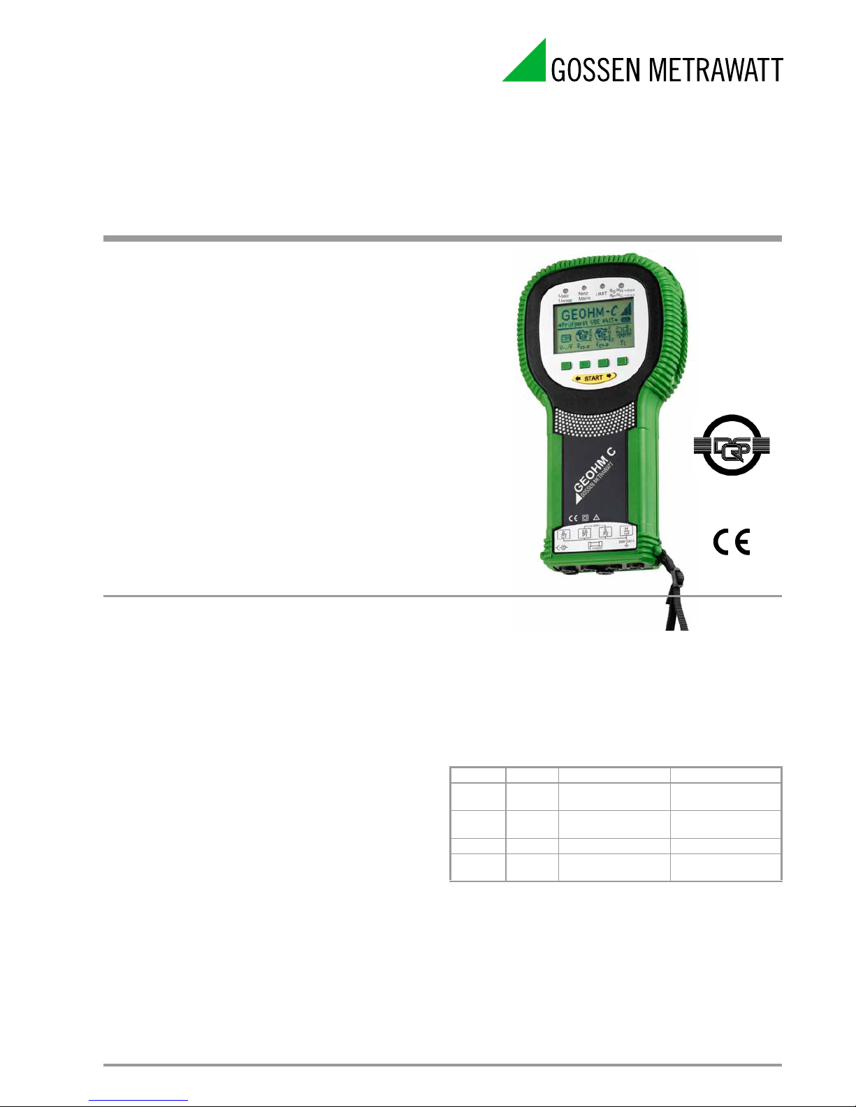
GEOHMC
Ground Resistance Tester
DQS certified per
DIN EN ISO 9001:2000
QUALITY MANAGEMENT SYSTEM
Reg.No.1262
Applications
The GEOHM
C is a compact instrument for the measurement of
ground resistance in electrical systems in accordance with:
DIN VDE 0100 Installation of power systems with
nominal voltages of up to 1000 V
DIN VDE 0141 Grounding in AC systems with nominal
voltages of greater than 1 kV
DIN VDE 0800 Installation and operation of telecom-
munications systems including data
processing systems: equipotential
bonding and grounding
Testing of lightning protection systems in accordance with
DIN VDE 0185
The instrument is also capable of determining soil resistivity which
is essential in calculating dimensions for grounding systems.
It can thus be taken advantage of for simple, geological surveys,
and for the planning of grounding systems.
Beyond this, ohmic resistance can be measured at both solid and
liquid conductors, as well as internal resistance at conductive
elements, as long as these are capacitance and induction-free.
Special Functions
• Hold function: The measurement value is frozen at the display
after the measurement key is released.
• Storage of measurement values to memory
• Data interface for the transmission of measurement values
and for software updates
• Convenient report generating software,
can be expanded into a comprehensive database
Display
The LCD consists of a backlit dot matrix
display at which menus, setup options, measuring results and
online help can be viewed. Various display languages can be
selected depending upon the country in which the instrument is
used.
Signal Lamps
The instrument automatically recognizes errors which occur
during measurement, and signals them with four LEDs as shown
in the table below.
Operation
The instrument is easy to operate. A multifunction key allows for
one-hand operation for menu selections and the initialization of
measurements. Basic functions and sub-functions are selected
with the help of four softkeys.
The instrument functions in accordance with the ammetervoltmeter principle, and thus requires no balancing. Automatic
measuring range selection, limit value monitoring and direct
selection of 3 or 4-wire measurement assure easy
operation as well.
LED Status Measuring Function Meaning
U
Stör/
U
noise
red Interference voltage U > 10 V
Netz
Mains
red Voltage Mains voltage is present
R
S
>max red Probe resistance Limit value exceeded
R
H
>max
red
Auxiliary earth electrode
resistance
Limit value exceeded
Battery operated tester for the measurement of ground resistance meets
international standards for performing such tests. This instrument allows
measurement of soil resistivity and ohmic resistance by means of the
ammeter-voltmeter test method.
Features
• 3 or 4-wire measurement selectable from menu
• No balancing required
• Continuous monitoring of interference voltage and
auxiliary earth electrode resistance with indication
of limit value violations
• Indication is displayed if maximum probe resistance is
exceeded at the beginning of the measurement
• Voltage measurement with automatic switch-over function
between direct voltage and alternating voltage:
Direct voltage measuring range 1.0 250 V
(with polarity display)
Alternating voltage measuring range 0 300 V
Page 2
GEOHMC
Ground Resistance Tester
2 GMC-I Messtechnik GmbH
Battery Monitoring and Self-Test
A battery symbol with five segments ranging from depleted to fully
charged continuously indicates the charging level of the batteries
in the main menu.
Automatic shutdown ensures if the batteries are fully depleted,
and the instrument includes an integrated charge monitoring
circuit for safe charging of rechargeable NiMH or NiCd batteries.
During the self-test, a series of test patterns can be displayed one
after the other, and indicator LEDs and relays are tested.
Rugged Housing for Harsh Operating Conditions
Soft plastic jacketing protects the instrument against damage due
to impact and dropping.
Data Interface
Measurement data can be uploaded to a PC via the integrated
IRDA interface for processing and archiving, or for the generation
of official reports
Software Updates
The test instrument can always be kept current thanks to device
software updates via the IRDA interface. Software updates are
performed during the course of re-calibration by our service
department, or by the user himself.
Applicable Regulations and Standards
Regulations and Standards for Use of the Test Instrument
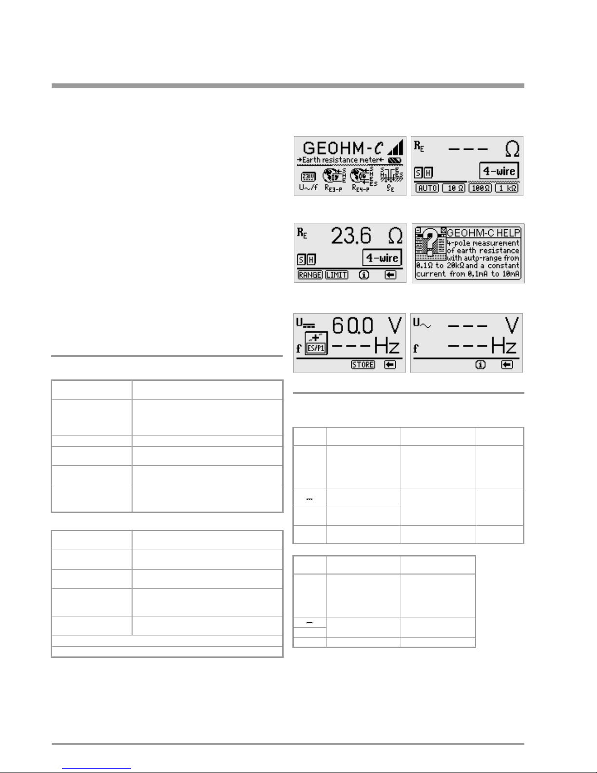
Sample Displays
Characteristic Values
1)
Manual measuring range selection only
2)
as from software version AD
3)
For sinusoidal measured quantities only
Output voltage: max. 50 V
rms
at 128 Hz 0.5 Hz
IEC 61010-1/EN 61 010-1/
VDE 0411-1
Safety requirements for electrical equipment for
measurement, control and laboratory use
IEC 61557/ EN 61 557/
VDE 0413
Devices for testing, measuring and monitoring protective
measures
Part 1: General requirements
Part 5: Earth resistance
DIN 43751 Part 1, 2 Digital measuring instruments
VDE 0106 Part 1 Protection against electrical shock, classification of
electrical and electronic equipment
EN 60529,
VDE 0470 Part 1
Test instruments and test procedures,
protection provided by enclosures (IP code)
DIN EN 61326-1
VDE 0843-20-1
Electrical equipment for measuement, control and
laboratory use – EMC requirements –
Part 1:General requirements
DIN VDE 0413 Part 5 Devices for testing, measuring and monitoring protective
measures
DIN VDE 0100 Regulations for the installation of power systems with
nominal voltages of up to 1000 V
DIN VDE 0141 Earthing in AC systems with nominal voltages of greater
than 1 kV.
DIN VDE 0800 Setup and operation of telecommunications systems
including electronic data processing:
equipotential bonding and grounding
DIN VDE 0185 Lightning protection systems – general installation
regulations
International regulations and standards
BS 7430 + BS 7671, NFC 15-100, IEC 60364
Measured
Quantity
Display Range Measuring Range Impedance /
Tes t Cur r ent
R
E
0.01 ... 20
0.1 ... 200
1 ... 2 k
10 ... 20 k
10 ... 50 k
1.0 ... 20
5 ... 200
50 ... 2 k
500 ... 20 k
500 ... 50 k
1)
10 mA
1mA
100 µA
100 µA
100 µA
U
2)
1,0 ... 99.9 V
100 ... 250 V
10 ... 250 V 500 k
U~
3)
0 ... 99.9 V
100 ... 300 V
f
3)
15 ... 99.9 Hz
100 ... 400 Hz
45 ... 200 Hz 500 k
Measured
Quantity
Intrinsic Uncertainty Measuring Uncertainty
R
E
(3% rdg.+6d)
(10% rdg. + 6d)
(10% rdg. + 6d)
(10% rdg. + 6d)
(10% rdg. + 6d)
(16% rdg. + 10d)
U
2)
(2% rdg.+2d) (4% rdg. + 3d)
U~
3)
f
3)
(0.1% rdg.+1d) (0,2% rdg. + 1d)
Main Menu
4-Wire Measurement
Online Help
Measuring Range Selection
Direct Voltage Measurement
Alternating Voltage Measurement
Page 3

GMC-I Messtechnik GmbH 3
GEOHMC
Ground Resistance Tester
Reference Conditions
Battery Voltage 5.5 V 1%
Ambient Temperature + 23 C 2 K
Relative Humidity 40
60%
Nominal Ranges of Use
Temperature Range 0 C +40C
Battery Voltage 4.5
6.5 V
Line Frequency 50/60 Hz 0.2 Hz
Line Voltage Waveshape sine (deviation between RMS
and rectified value 1%)
Nominal Conditions of Use
Series Mode
Interference Voltage < 3 V AC DC
Additional Error caused by
Probe and Auxiliary Earth
Electrode Resistance < 5% of (R
E
+ RA + RP)
Max. Probe Resistance < 70 k
Max. Auxiliary Earth
Electrode Resistance < 50 k
Max. Earth and Auxiliary Earth
Electrode Resistance 50 k, see Figure RE as a function
of R
H
Ambient Conditions
Operating Temperature –10 ... + 50 C
Storage Temperature – 20 ... + 60 C (without batteries)
Relative Humidity max. 75%,
no condensation allowed
Elevation max. 2000 m
Power Supply
Batteries 4 ea. 1.5 V C-size (4 x C-Size)
(alkaline-manganese per IEC LR14)
Battery Voltage 4.6 6.5 V
Battery Service Life 30 h or 1000 measurements at R
E
(with 10 s on-time, each measurement
performed until the instrument switches
off automatically, without display
illumination)
Rechargeable Batteries NiCd or NiMH
Battery Charger NA 0100S (Article No. Z501D),
(not included) 3.5 mm jack plug
Charging Voltage 9 V
Charging Time approx. 9 hours
As a rule, fewer measurements can be performed with
rechargeable batteries due to their limited charging capacity.
Electrical Safety
Safety Class II per IEC 61 010-1
Operating Voltage 250 V
Tes t V o l ta ge 2. 3 kV
Measuring Category 250 V CAT II
Pollution Degree 2
Fuse F0.1H250V
Electromagnetic Compatibility (EMC)
Interference Emission/Immunity IEC 61 326/EN 61 326
Data Interface
Type infrared interface (SIR/IrDa)
bidirectional, half-duplex
Format 9600 baud, 1 start bit, 1 stop bit, 8 data
bits, no parity, no handshake
Range
max. 10 cm recommended distance: < 4 cm
Mechanical Design
Display multiple dot matrix display, 128 x 64
pixels (65 mm x 38 mm), illuminated
Dimensions 275 mm x 140 mm x 65 mm
Weight approx. 1.2 kg with batteries
Protection housing: IP 54 per EN 60529
with pressure compensating diaphragm
of microporous ePTFE, non-ageing,
8 mm dia. in battery compartment lid
Extract from table on the meaning of IP codes
Standard Equipment
1 GEOHMC test instrument
1 carrying strap
1 set of batteries
1 factory calibration certificate
1
set of comprehensive instructions covering the following topics:
– Measurement of earth resistance
with instructions for 3 and 4-wire methods,
with physical considerations regarding the potential
gradient area as related to dissipation resistance of
grounding systems of various size,
with important tips for the performance of measurements
on difficult terrain
– Measurement of soil resistivity with geologic analysis
and calculation of dissipation resistance
– Measurement of ohmic resistance
1 PC software WinProfi for communication with GEOHM
C.
The PS3 CD-ROM includes the software WinProfi with the following content and functions:
• up-to-date test instrument software
– for loading other user interface languages
– for loading firmware version updates
• Transmission of measured data from test instrument to PC
0,5
25
50
0,5 25
50
RH [k]
R
E
[k]
IP XY
(1
st
digit X)
Protection against
foreign object entry
IP XY
(2nd digit Y)
Protection against the
penetration of water
3 2.5 mm
3 spraying water
4 1.0 mm
4 splashing water
5 dust protected 5 water jets
Page 4

Edited in Germany • Subject to change without notice • A pdf version is available on the internet.
GEOHMC
Ground Resistance Tester
GMC-I Messtechnik GmbH
Südwestpark 15
90449 Nürnberg •
Germany
Phone +49 911 8602-111
Fax +49 911 8602-777
E-Mail info@gossenmetrawatt.com
www.gossenmetrawatt.com
Accessories
E-Set 3, Earth Testing Set
E-Set 4, Earth Testing Set
E-Set 5, Earth Testing Set
Order Information
For additional information on accessories, please refer to
• our Measuring Instruments and Testers Catalog
• our website www.gossenmetrawatt.com
Designation Type Article Number
Basic Instrument
Digital Earth Tester GEOHM
C M590A
Add-Ons
IR interface for connection to a USB
port at a PC for data exchange
between the PC and the GEOHM
C,
e.g. for software updates to the
tester or visualization of measurement values at the PC IrDa-USB Converter Z501J
Accessories
4 special NiMH baby cells
(rechargeable) Akku-Set GTY1040042E25
Adapter for charging batteries inside
the GEOHM
C NA102 Z501N
Hard-shell case with compartment
for one C series test instrument and
accessories HC30-C Z541C
Earth testing set:
Synthetic leather case with 2 reels,
two 25 measurement cables, one
40 m measurement cable, two 3 m
measurement cables, 4 earth spikes
(zinc plated), 2 spike pullers and 1
hammer E-Set 3 GTZ3301005R0001
Earth testing set:
Synthetic leather case with 2 reels,
two 25 m cables, one 40 m cable,
two 3 m measurement cables and
4 earth drills E-Set 4 Z590A
Earth testing set:
Carrying case accommodating GEOHMC
1 drum with 25 m measurement cable
2 drums with 50 m measurement
cable each
4 measurement cables,
3 x 0.5 m long, 1 x 2 m long
1 test clamp
4 earth drills, each 350 mm long
1 dust cloth
2 pads of earth testing
measurement data forms E-Set 5 Z590B
Reel with 25 m measurement cable
and banana plugs at both ends TR25 GTZ3303000R0001
Drum with 50 m measurement
cable, banana plug / jack socket TR50 GTY1040014E34
Earth drill, 35 cm long,
can be connected by means of
4 mm banana plugs SP350 GTZ3304000R0001
 Loading...