

Page 1

User manual
E-Clip 1 / E-Clip 2
Current Clamps
20 751 208
3-349-447-03
1/12.07
Page 2

E-Clip 1 / E-Clip 2 Current Clamps
Table of contents
1. WARNINGS ..............................................................................................................2
2. DESCRIPTION OF CURRENT CLAMPS................................................................. 3
3. MAINTENANCE........................................................................................................3
3.1. INSPECTION .............................................................................................................3
3.2. CLEANING................................................................................................................4
3.3. SERVICE AND CALIBRATION .......................................................................................4
4. CURRENT CLAMP OPERATION ............................................................................ 4
4.1. SUBSTITUTE ELECTRIC MODEL FOR CURRENT CLAMPS.................................................4
4.2. TYPICAL APPLICATIONS ............................................................................................. 5
5. SPECIFICATIONS....................................................................................................6
5.1. GENERAL PURPOSE CURRENT CLAMP WITH CURRENT OUTPUT ..................................... 6
5.2. SENSITIVE CURRENT CLAMPS WITH CURRENT OUTPUT ................................................. 6
5.3. GENERAL (ALL TYPES) ..............................................................................................7
1. Warnings
To ensure a high level of operator's safety during using of current clamps the following warnings
have to be considered:
♦ Do not use the current clamp if any damage is noticed!
♦ Do not leave open nodes of the current clamp with current output (E-Clip 1, E-Clip 2)
during measurement to avoid damage and electric shock on secondary side, never
enclose conductor in the jaw unless the clamp is connected to measuring instrument!
♦ Only a competent, authorized person is allowed to carry out service intervention!
♦ Consider all generally known precautions in order to avoid risk of electric shock
while dealing with electric installations!
♦ Do not extend hands over safety barrier to prevent of electric shock! Only handles are
allowed to be touched during measurement!
♦
♦
♦ If the current clamp is used in a manner not specified in this User manual, the
Symbol on the current clamp indicates the possibility to use the current clamp on
non-insulated conductors.
Symbol on the current clamp indicates the possibility of a hazardous live
!
condition if the operator ignores the required safety measures.
provided protection can be impaired!
2
Page 3
E-Clip 1 / E-Clip 2 Current Clamps
2. Description of current clamps
The E-Clip 1and E-Clip 2 are 1000/1 ratio current clamps for measuring alternating currents in
the range from 1 mA to 1000 A (depending on the type).
They can be connected to any power analyzer, energy analyzer, harmonics analyzer,
multimeter, earth resistance meters, electrical installation testers and other measuring
instruments with compatible voltage or current inputs.
In chapter 4 some typical current clamp applications are described.
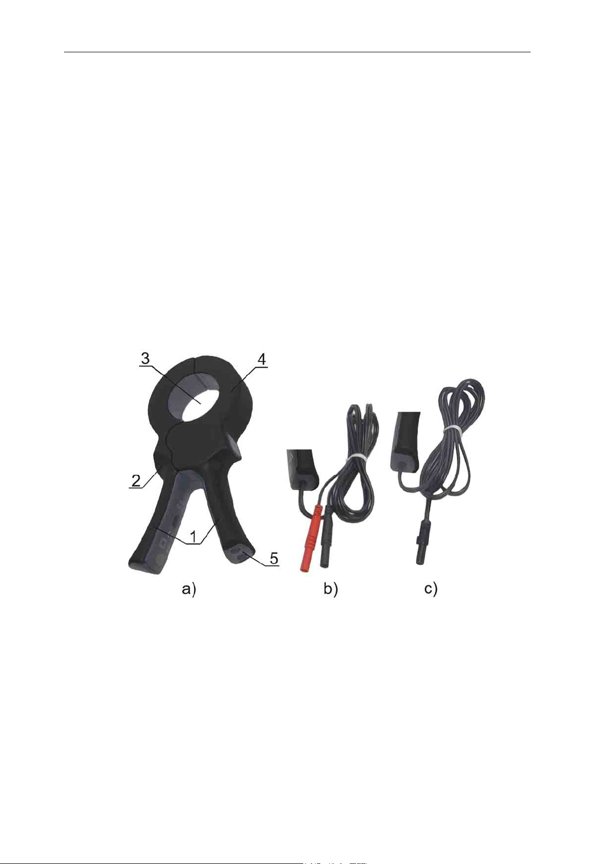
The current transducer is housed in a plastic case that maintains the protection class defined in
technical specifications. It consists of:
1. Handles,
2. Safety barrier,
3. Conductor opening,
4. Current transformer,
5. Connection with:
a) Safety banana sokets (E-Clip 2),
b) Cable connection (length = 1.5 m) with safety banana terminals
(E-Clip 1),
3. Maintenance
3.1. Inspection
To maintain operator safety and ensure reliability of the current clamp it is good practice to
inspect it on a regular basis. Check that the enclosure and optional connection are without
defects such as scratches or breaks.
Jaw surface must be clean. Pollution on jaw surfaces reduces the current clamp sensitivity.
3
Page 4

E-Clip 1 / E-Clip 2 Current Clamps
)
3.2. Cleaning
Use a soft cloth moistened with soapy water or alcohol to clean non-metallic surface of the
current clamps and leave them to dry totally before using it.
Notes!
• Do not use liquids based on petrol or hydrocarbons!
• Do not spill cleaning liquid over the current clamps!
To clean jaw cut surfaces use slightly oiled soft cloth.
3.3. Service and calibration
It is essential that your clamp is regularly calibrated in order to guarantee the technical
specification listed in this User manual. We recommend 2-year calibration interval.
Metrel encloses an original calibration certificate with every new instrument and clamp.
For recalibration and repairs under or out of warranty time please contact your distributor for
further information.
4. Current clamp operation
4.1. Substitute electric model for current clamps
Equivalent circuit diagram for current clamp measurement:
Is
Im
Im
Symbols on circuit diagrams have following meaning:
Im Measured (AC) current, primary current
Is Measured current, current transformer secondary current
N1 Number of primary turns - normally N1=1 for current clamps
N2 Number of secondary turns (1000 for all types)
I A-meter
Measuring resistor
R
L
U V-meter
N1
N2
Clamp
current transformer
N1
N2
Clamp
current transformer
Is
a)
R
L
b
I
U
4
Page 5

E-Clip 1 / E-Clip 2 Current Clamps
Clamp current transformer must always have a low impedance load on its secondary side. This
loading is realized with an A-meter (for current sensors with current output). Current clamp with
voltage output already contains the load resistor and its output voltage is proportional to
measured current.
The N1:N2 ratio (primary to secondary winding turns ratio) defines the step-down current ratio
and sensitivity of current clamps. For N2 = 1000 the sensitivity is defined as
1 mA / 1 A, i.e.: 1 mA of output current is generated from 1 A primary current for
N1 = 1. The general formula for sensitivity are given below:
N
= for current output, and
1
II
mS
N
2
N
1
N
R
Lm
2
IU
= for voltage output.
N1 is always integer and means number of passes of conductor carrying measured current
through conductor opening of current clamp.
4.2. Typical applications
Some typical applications of current measurement for standard sensitive current clamps
(E-Clip 2) in combination with appropriate measuring instrument:
- Harmonic analysis,
- Measuring electrical power,
- Measuring current and energy consumption,
- Functional testing of appliances, machines,
- Measuring equipment inrush current, etc.
Additional applications related to low current measurements can be covered with high sensitive
type current clamps (E-Clip 1):
- Measurement of PE leakage current,
- Measurement of differential current and/or current difference,
- Contactless measurement of earth resistance,
- Determining problems in lighting and grounding systems.
5
Page 6

E-Clip 1 / E-Clip 2 Current Clamps
5. Specifications
5.1. General purpose current clamp with current output
Type: E-Clip 2
Rated current: 1000 A
Current ratio : 1000:1
Output:1 mA/A, safety banana sockets
Electrical characteristics (at R = 1 Ω):
Measuring range: 0.2 A ÷ 1200 A
Output signal: 0.2 mA ÷ 1.2 A (0.2 A ÷ 1200 A)
Accuracy and phase error:
Primary current [A] 0.1 ÷ 10 10 50 200 1000 1200
Accuracy of output current [%]
Phase error [°]
Frequency range: 40 Hz ÷ 5 kHz
Continuity of measurements:
Load impedance:
Working voltage: 600 V max.
Influence of neighbor conductor: <1 mA/A at 50 Hz
Influence of conductor position <0.3 % at f < 400 Hz
Influence of loading:
Influence of DC current offset: <2.5 % for I
5.2. Sensitive current clamps with current output
Φ
4 mm
≤2.5 ≤2 ≤1.5 ≤0.9 ≤0.7 ≤0.7
n.a.
1000 A r.m.s. (f < 1 kHz) continuous
1200 A r.m.s. (40 min / 20 min intermitted)
≤10 Ω
2 Ω to 10 Ω: 1 % and 1 °
≤3 ≤1.7 ≤0.9 ≤0.7 ≤0.7
< 30 A
DC
Type: E-Clip 1
Rated current: 1000 A
Current ratio : 1000:1
Output: 1 mA/A, safety banana plugs
Electrical characteristics (R = 1 Ω)
Current measuring range: 0.001 A ÷ 1200 A
Output signal: 1 μA ÷ 1.2 A (1 mA ÷ 1200 A)
Accuracy and phase error
Primary current [A]
Accuracy of output current
[%]
Phase error [°]
Frequency range: 40 Hz..5 kHz
Continuity of measurements: 1000 A r.m.s. (f < 1kHz) continuous
Load impedance:
Working voltage: 600 V max.
Influence of neighbor conductor: <1 mA/A at 50 Hz
Φ
4mm
0.1m ÷ 100m 0.1 ÷ 1 1 ÷ 10 10 ÷ 100 100 ÷ 1200
≤3 ≤2 ≤1.2 ≤1 ≤0.5
n.a. n.a.
1200 A r.m.s. (40 min / 20 min intermitted)
≤10 Ω
≤2.2 ≤1 ≤0.7
6
Page 7

E-Clip 1 / E-Clip 2 Current Clamps
Influence of conductor position <0.3 % at f < 400 Hz
Influence of loading:
Influence of DC current offset: <2.5 % for I
2 Ω to 10 Ω: 1 % and 1°
< 15 A
DC
5.3. General (all types)
Safety specification
Over voltage category: 600 V CAT III,
Pollution degree: 2
Double insulation
Mechanical data
Jaw opening: 52 mm
Maximum conductor sizes:
cable: Φ 50 mm
Environment conditions
Working temperature: -10 °C ÷ 50 °C
Storage temperature: -30 °C ÷ 70 °C
Humidity: 0 % ÷ 85 %, linearly decreasing for T
> 35 °C
Altitude: working 0 to 2000 m
Applied standards
Safety: EN/IEC 61010-1
EN/IEC 61010-2-32
bar: 1 bar 50 mm x 5 mm,
4 bars 30 mm x 5 mm
Flammability of plastic housing:
UL94 – UV1
Dimension: 220 mm x 120 mm x 48 mm
Weight: 600 g
Other outputs availability
Contact manufacturer or local distributor for
further information.
7
Page 8

Repair and Replacement Parts Service
DKD Calibration Lab
and Rental Instrument Service
When you need service, please contact:
GMC-I Gossen-Metrawatt GmbH
Service-Center
Thomas-Mann-Straße 20
90471 Nürnberg ● Germany
Phone +49 911 8602-0
Fax +49 911 8602-253
E-Mail service@gossenmetrawatt.com
This address is only valid in Germany.
Please contact our representatives or subsidiaries for service in other countries.
Product Support
When you need support, please contact:
GMC-I Gossen-Metrawatt GmbH
Product Support Hotline
Phone +49 911 8602-112
Fax +49 911 8602-709
E-Mail support@gossenmetrawatt.com
GMC-I Gossen Metrawatt GmbH
Thomas-Mann-Str. 16-20
90471 Nürnberg • Germany
Phone +49 911 8602-111
Fax +49 911 8602-777
E-Mail info@gossenmetrawatt.com
www. gossenmetrawatt.com
 Loading...