

Page 1
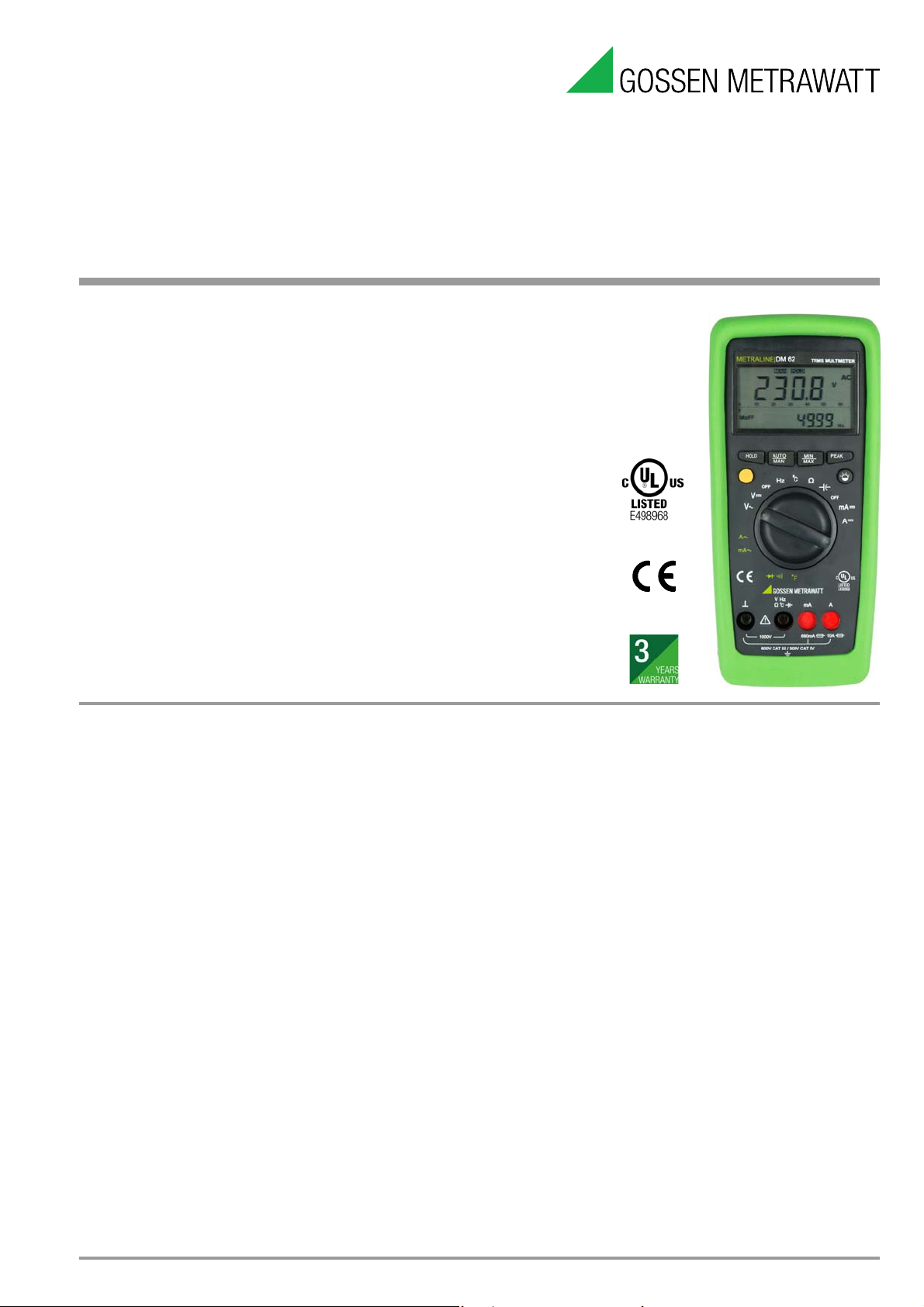
METRALINE DM 61/62
Analog-Digital Multimeter
• Voltage: DC / AC 100 μV ... 1000 V
• Current: DC / AC: 10 μA ... 660.0 mA (DM 61) / 10.00A (DM 62)
• Clip function 1000:1 for current transformers (DM 61 only)
• Resistance: 100 mΩ... 60.00 MΩ
• Capacitance: 1 pF ... 40.00 mF (DM 62 only)
• Frequency: 10.00 Hz ... 10.00 MHz (DM 62 only)
• Diode / Continuity
• Duty cycle (%) measurement (DM 62 only)
• Temperature TC with K-type: –50 ... 1300 °C
• TRMS bandwidth: 2 kHz (DM 62 only)
• Hold / Peak / Min-Max / Relative (Zero)
• Auto / Manual ranging
• Dual digital display with analog scale and backlight
• ABS Automatic Blocking Sockets
• UL Certification
•3 year warranty
3-447-012-03
6/1.19
Features
Automatic Blocking Sockets (ABS) *
Automatic blocking sockets prevent incorrect connection of
measurement cables and inadvertent selection of the wrong
measured quantity. This significantly reduces danger to the user,
the instrument and the system under test, and eliminates it
entirely in many cases.
Automatic / Manual Measuring Range Selection
Measured quantities are selected with the rotary switch. The
measuring range is automatically matched to measured values.
The measuring range can be selected manually as well with the
help of the AUTO/MAN key.
Display of Negative Values at the Analog Scale
Negative values are also displayed at the analog scale for zerofrequency quantities, allowing for observation of measured
quantity fluctuation around the zero-point.
Storage of Measured Values
By pressing the HOLD/MIN/MAX key, the currently displayed
measurement value can be „frozen“ in the display.
The minimum and maximum values which were present at the
input of the measuring instrument after activation of the MIN/MAX
mode can be selectively "retained" with the MIN/ MAX function.
The most important application is the determination of the
minimum or maximum value during long-term observation of
measurement quantities. MIN/MAX has no effect on the analog
display; it continues to display the current measurement value.
Continuity Test
Allows for the detection of short-circuits and interrupted
conductors. In addition to displaying test results, an acoustic
signal can also be generated if desired.
Power Saving Circuit
The device is switched off automatically if the measured value
remains unchanged for a period of approximately 15 minutes, and
if none of the controls are activated during this time. Automatic
shutdown can be deactivated.
Protective Cover for Harsh Conditions
The instrument is protected against damage in the event of
impacts or dropping by means of a soft rubber cover with tilt
stand. The rubber material also assures that the instrument does
not wander if it is set up on a vibrating surface.
Duty Cycle Measurement – Square-Wave Signals
This function makes it possible to test circuits and transmission
cables by measuring the frequency and the duty cycle of pulses.
Voluntary Manufacturer’s Warranty
36 months for material and workmanship
* Patented (patent no. EP 1801 598, US 7,439,725)
GMC-I Messtechnik GmbH
Page 2
METRALINE DM 61/62
Analog-Digital Multimeter
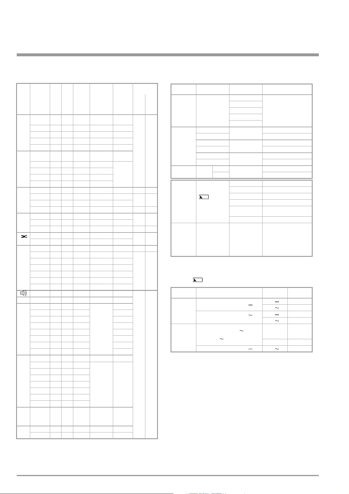
Characteristic Values
Meas.
Measuring
Func-
Range
tion
660.0 mV • • 100 μV
6.600 V • • 1 mV
V(DC)
66.00 V • • 10 mV
660.0 V • • 100 mV
1000 V • • 1 V
660.0 mV • • 100 μV
6.600 V • • 1 mV
V(AC)
66.00 V • • 10 mV
660.0 V • • 100 mV
1000 V • • 1 V
66.00 mA • • 10 μA 66.00 mV 0.8 + 5
A(DC)
660.0 mA • • 100 μA 66.00 mV 0.8 + 5
10.00 A
66.00 mA • • 10 μA 66.00 mV 0.8 + 5
A(AC)
660.0 mA • • 100 μA 66.00 mV 0.8 + 5
10.00 A
66.00 A • — 10 mA 66.00 mV 0.8 + 5
5)
(AC)
660.0 A • — 100 mA 66.00 mV 0.8 + 5
660.0 Ω • • 100 mΩ –3.3 V 0.8 + 5
6.600 kΩ ••1 Ω –1.08 V 0.8 + 5
66.00 kΩ ••10 Ω –1.08 V 0.8 + 5
Ω
660.0 kΩ • • 100 Ω –1.08 V 0.8 + 5
6.600 MΩ ••1 kΩ –1.08 V 1.0 + 5
66.00 MΩ ••10 kΩ –1.08 V 2.0 + 5
660.0 Ω • • 100 mΩ –3.3 V 0.8 + 5
DIODE 2.000 V • • 1 mV 3.3 V 2.0 + 10
6.600 nF — • 1 pF
66.00 nF — • 10 pF 2.0 + 10
660.0 nF — • 100 pF 2.0 + 10
6.600 μF — • 1 nF 2.0 + 10
F
66.00 μF — • 10 nF 2.0 + 10
660.0 μF — • 100 nF 5.0 + 10
6.600 mF — • 1 μF 5.0 + 10
40.00 mF — • 10 μF 5.0 + 10
66.00 Hz — • 0.01 Hz
660.0 Hz — • 0.1 Hz
6.600 kHz — • 1 Hz
Hz
66.00 kHz — • 10 Hz
660.0 kHz — • 100 Hz
6.600 MHz — • 1 kHz
10.00 MHz — • 10 kHz
1.0 ... 98.90%
%
0 ... 1300 °C
°C/°F
–50 ... 0 °C
1)
At 0 °C ... + 40 °C
2)
At input > 3.5 Vrms, typical 5 Vp-p, square wave, bipolar inputs
3)
For < 10 kHz at 5 Vp-p, square wave, bipolar inputs
4)
Without sensor
5)
Display with current transformers 1000 : 1
6)
Limited by 10 A fuse
DM61 DM62
6)
— • 10 mA 10.00 mV 1.5 + 5 — —
6)
— • 10 mA 10.00 mV 1.5 + 5 — —
(TRMS)
Resolution
Input
Impedance
>100 MΩ //
<40pF
11 MΩ //<40pF
10 MΩ // <40pF
10 MΩ // <40pF
10 MΩ // <40pF
>100 MΩ //
<40pF
11 MΩ //<40pF
10 MΩ // <40pF
10 MΩ // <40pF
10 MΩ // <40pF
Voltage Drop
No load Voltage
—
Digital display Inherent
deviation at
reference
condition
+(...%rdg
+...digits)
0.7 + 5
0.4 + 5
0.4 + 5
0.4 + 5
0.4 + 5
1.2 + 5
1.0 + 3
3.0 + 40
f min
10 Hz 0.2 + 2
— • 0.01 %
••1 °C
••1 °
C
0.9% (% min)
10 Hz ... 1 kHz
±5 Digit 3)
1...10 kHz;
±
5 Digit/kHz
— 2.0 + 3
—2.0 ±10
Overload
capacity
Overload
values
1000 V
eff/rms
Sine
wave
0.7 A Cont.
0.7 A Cont.
0.7 A Cont.
1000 V
eff/rms
Sine
wave
1000 V
eff/rms
Sine
wave
2)
4)
4)
DC
AC
DC
AC
DC
AC
1)
Overload
duration
Cont.
max.
10 s
max.
10 s
Influencing Quantities and Influence Error
Influencing
Quantity
Temperature
Measured
Quantity
Frequency
Battery
Volta ge
Relative
Humidity
1)
With temperature: Error data apply per 10 K change in temperature. With frequen-
cy: Error data apply to a display from 300 digits onwards.
2)
With unknown waveform (crest factor CF > 2), measure with manual range selection
3)
With the exception of sinusoidal waveform.
4)
After the „ “ symbol is displayed.
Influencing
Quantity
Common Mode
Interference
Volta ge
Normal Mode
Interference
Volta ge
Range of Influence
0 °C ... +21 °C
and
+25 °C ... +40 °C
20 Hz ... < 50 Hz
> 50 Hz ... 200 Hz 5.0 + 3
20 Hz ... < 50 Hz
>50Hz...2kHz 5.0+7
> 50 Hz ... 200 Hz
20 Hz ... < 2 kHz 5.0 + 3
Crest
Factor CF
4)
... < 2.49
V
> 2.49 V ... 3 V
75%
3 days
Meter off
Noise quantity max. 1000 V
Noise quantity max. 1000 V
50 Hz, 60 Hz sinusoidal
Noise quantity: V ,
value of the measuring range at a time
max. 1000 V , 50 Hz, 60 Hz sinusoidal
Noise quantity max. 1000 V V > 45 dB
Measured Quantity/
Measuring Range
V DC, V AC
A DC, A AC
F, Hz, %, °C
660 mV~
6.6 ... 1000 V~
1 ... 1.4
1.4 ... 5
Range of Influence
V~
2)
V~, A DC 10 Digit
6.600 kΩ ...
66.00 MΩ
nF, F, mF, Hz, % 5 Digit
V~, V DC
A~, A DC
Influence Error1)
±(... % of rdg. + ... digits)
Ω
Diode
A~
3)
3)
, A~
V DC 5 Digit
A AC 6 Digit
660 Ω 4 Digit
Ω
F
Hz
°C
%
1 x Intrinsic uncertainty/K
1.0 + 3
1.0 + 3
1.0 + 3
±1% of rdg
±5% of rdg
3 Digit
1 x intrinsic uncertainty
Measuring
Range
V > 100 dB
V > 100 dB
V > 100 dB
V>50dB
660 mV, 6.6 V,
660 V, 1000 V
DC
66 V DC > 35 dB
Attenuation
> 43 dB
Display
Liquid crystal display (58 mm x 31.4 mm) with analog indication
and digital display and with display of the unit of measured
quantity, function and various special functions.
Analog
Indication LCD scale with bar graph
Scale length 55 mm
Scaling 65 scale divisions during all the
measurement
Polarity indication With automatic reversal
Overrange indication By triangle
Sampling rate 28 times/s
2 GMC-I Messtechnik GmbH
Page 3

METRALINE DM 61/62
Analog-Digital Multimeter
Digital
Height of Main
Display numerals 7 segment numerals: 12 mm
Height of Sub
Display numerals 7 segment numerals: 7 mm
Number of counts 4 digit: 6600 steps
Overrange display „OL“ is shown
Polarity display „–“ sign is shown, When positive pole
connected to „ “
Sampling rate 2.8 times/s
Power supply
Battery 2 AA size batteries alkaline manganese
cells as per IEC LR6.
Service life for METRALINE DM 61:
600 hrs. for V DC, A DC
300 hrs. for V AC, A AC
for METRALINE DM 62:
400 hrs. for V DC, A DC
200 hrs. for V AC, A AC
Battery test Automatic display of „ “ symbol when
battery voltage falls below following value:
approx. 2.4 V.
Electromagnetic compatibility (EMC)
Emission EN 61326: 2013 Class B
Response Time (after manual range selection)
Measured Quantity/
Measuring Range
V , V , °C 0.1 s 1 s from 0 to 80%
A , A 0.1 s 1 s
660 Ω ... 6.6 MΩ 0.1 s 1 s
66 MΩ 0.2 s 2 s
6.6 nF ... 66 μF 0.7 s max. 1 s
660 μF ... 6.6 mF 1.4 s max. 3 s
66 mF 7.0 s max. 15 s
660 Hz, 6.6 kHz 2.0 s max. 2 s
66 kHz, 660 kHz, 1 MHz 0.5 s max. 1 s
% (≥ 10 Hz) 0.7 s max. 2.5 s
Response Time
Analog
Display
0.1 s 1 s
Digital Display
Transient response for
step function of the
of the upper range limit
of the upper range limit
of the upper range limit
Reference conditions
Ambient temperature 23 °C+ 2 K
Relative humidity 45% ... 55 % RH
Frequency of
measured quantity 50 or 60 Hz ±2%
Waveform of the
measured quantity sinusoidal
Battery voltage 3 V ±0.1 V
measured quantity
from 0 to 50%
from 0 to 80%
Immunity IEC 61000-4-2:
8 kV atmosphere discharge
4 kV contact discharge
IEC 61000-4-3: 3 V/m
Short-term measured value deviation may occur during electromagnetic interference
thus reducing the specified operating quality.
Safety: IEC 61010-1-2010
Measuring category 600 V CAT III, 300 V CAT IV
The maximum voltage of 1000 V may only
be used with CAT II.
High Voltage Test 6.7 kV (IEC 61010-1-2010)
Fuses
Fuse for up to 660 mA ranges
FF (UR) 1.6 A/1000 V AC/DC; 6.3 mm X 32 mm; rating 10 kA
with 1000 VAC/DC and ohmic load; in conjunction with power
diodes, protects all current measuring ranges up to 660 mA.
Fuse for up to 10 A ranges (METRALINE DM 62)
FF (UR)10 A/1000 V AC/DC; 10 mm x 38 mm; rating 30 kA with
1000 VAC/DC and ohmic load; protects the 10 A ranges up to
1000 V AC/DC.
Defective fuses are not displayed.
Environmental conditions
Functional
temperature range 0 °C ... +50 °C
Storage
temperature range –25 °C ... +70 °C (without batteries)
Relative humidity 45 ... 75 %
Altitude up to 2000 m
Mechanical configuration
Protection
for the meter IP50
Pollution degree 2
Connection sockets IP20 according to
EN 60529 / DIN VDE 0470-1
Dimensions with holster: 86 mm x 188 mm x 53 mm
without holster: 79 mm x 174 mm x 38 mm
Weight
480 g approx., including battery and holster
Applicable Regulations and Standards
IEC 61010-1/EN 61 010-1/
VDE 0411-1
EN 60529
VDE 0470, Part 1
DIN EN 61326-2-1
VDE 0843-02-2-1
DIN EN 60529
DIN VDE 0470 Part 1
Safety requirements for electrical equipment for
measurement, control and laboratory use
Test instruments and test procedures
Protection provided by enclosures (IP code)
Electrical equipment for measurement, control and laboratory use – EMC requirements –
Part 2-1: Particular requirements for sensitive test and
measurement equipment
Test Instruments and test procedures
– Degree of protection provided by enclosures (IP code)
GMC-I Messtechnik GmbH 3
Page 4

METRALINE DM 61/62
Analog-Digital Multimeter
Standard Equipment
1Multimeter
1 Rubber holster with carrying strap
1Cable set
1Battery set
1 Operating instructions
1Test report
Order Information
Description Type Article Number
Clipping multimeter, clip factor 1:1000
for current measurement with optional
clamp WZ1001 as accessory METRALINE DM 61 M194A
TRMS Multimeter METRALINE DM 62 M197A
Accessories
AC clamp 1000:1 WZ1001 Z194A
For additional information on accessories, please refer to
• our „Measuring Instruments and Testers“ catalogue
• our website www.gossenmetrawatt.com
Edited in Germany • Subject to ch ange without notice • A pdf version is available on the Internet
GMC-I Messtechnik GmbH
Südwestpark 15
90449 Nürnberg •
Germany
Phone +49 911 8602-111
Fax +49 911 8602-777
E-Mail info@gossenmetrawatt.com
www.gossenmetrawatt.com
 Loading...