

Page 1
Operating Instructions
METRACELL BT PRO
Portable Battery Tester
3-447-058-03
1/4.20
Page 2

METRACELL BT PRO GMC-I Messtechnik GmbH
Table of Contents
1 Safety Precautions..............................................................1
2 Important Information .........................................................2
2.1 Intended Use /
Use for Intended Purpose ................................................2
2.2 Use for Other than Intended Purpose...............................2
2.3 Liability and Guarantee ....................................................2
2.4 Opening the Instrument / Repairs ....................................2
3 Documentation....................................................................2
3.1 Identifiers .........................................................................2
3.2 Definition of Terms...........................................................2
4 Getting Started....................................................................3
5 The Instrument....................................................................3
5.1 Scope of Delivery............................................................. 3
5.2 Optional Accessories .......................................................3
5.3 Instrument Overview ........................................................3
5.4 Relevant Standards .........................................................4
5.5 Measurement Inputs........................................................5
5.6 LCD Display.....................................................................5
5.7 Function Keys / Navigation ..............................................5
5.8 RFID Reader ....................................................................5
5.9 Attachment Options.........................................................5
5.10 Technical Data.................................................................6
5.11 Characteristic Values .......................................................6
6 Operation ............................................................................7
6.1 Power Supply (rechargeable batteries).............................7
6.2 Switching the Instrument On/Off ......................................7
6.3 System Settings...............................................................8
6.4 Establishing and Terminating Wireless Connections ......... 8
6.5 Testing the RFID Reader..................................................9
7 Menu and Functions .........................................................10
7.1 Overview........................................................................10
7.2 Display Menu.................................................................12
7.3 Measurement Menu.......................................................12
7.4 Data Menu.....................................................................15
7.5 The SETTINGS Menu.....................................................16
7.6 INFO Menu ....................................................................17
10 Performing Measurements ............................................... 30
10.1 General Information........................................................30
10.2 Multimeter Measurements..............................................32
10.3 Charge Retention Measurement.....................................33
10.4 Discharge Measurement ................................................35
10.5 Charge Measurement ....................................................37
10.6 Resistance Measurement...............................................39
10.7 Temperature Measurement............................................41
10.8 Connector Measurement ...............................................43
10.9 Interval U Measurement .................................................45
10.10 Interval U+I Measurement ..............................................47
10.11 DMA35 Measurement (IrDA)...........................................49
10.12 DMA35 Measurement (BT).............................................49
11 Viewing, Editing, Transferring and Evaluating Measured
Values ............................................................................... 50
11.1 Viewing Measured Values / Measured Value Details at the
Instrument......................................................................50
11.2 Viewing Measured Value Evaluations at the Instrument ..50
11.3 Excluding a Measurement from Transmission (deactivate
measurement)................................................................50
11.4 Deleting Measured Values..............................................50
11.5 Saving Measured Values to a PC (data backup).............50
12 Maintenance ..................................................................... 52
12.1 Firmware Update ...........................................................52
12.2 Housing and Display ......................................................52
12.3 Measurement Cables .....................................................52
12.4 Fuse...............................................................................53
12.5 Accessories ...................................................................53
13 Service and Support .........................................................53
13.1 Product Support ............................................................53
13.2 Repair and Replacement Parts Service
Calibration Center * and Rental Instrument Service ........53
14 CE Declaration ..................................................................54
15 Returns and Environmentally Sound Disposal.................. 54
8 “BT PRO Manager” PC Software.......................................18
8.1 Installation, Launching the Program and Update............18
8.2 Overview........................................................................18
8.3 Defining the Data(base) Storage Location ......................18
8.4 Managing User Accounts............................................... 19
8.5 Basic Setting: Specifying the Temperature Unit of
Measure ........................................................................20
8.6 Creating and Managing the Battery Database................ 20
8.7 Transferring the Battery Database to the Battery Tester . 23
8.8 Assigning RFID Tags to Batteries (DUTs)........................24
8.9 Importing Measurement Data......................................... 24
8.10 Viewing Measurement Series and Creating Measurement
Evaluations (reports).......................................................25
9 Preparing Measurements..................................................28
9.1 General Information (procedure).....................................28
9.2 Switching Polarity On or Off ...........................................28
9.3 Connecting Measuring Accessories ...............................28
Page 3

GMC-I Messtechnik GmbH METRACELL BT PRO
1 Safety Precautions
Observe this documentation, in particular all included safety information, in order to protect yourself and others from injury, and to
prevent damage to the instrument.
• Carefully and completely read and adhere to these operating
instructions, as well as the instrument’s condensed operating
instructions.
The respective documents can be found at
http://www.gossenmetrawatt.com. Retain these documents
for future reference.
• Use only the specified accessories with the instrument!
• Carefully and completely read and adhere to the product documentation for optional accessories. Retain these documents
for future reference.
• Tests may only be performed by a qualified electrician, or
under the supervision and direction of a qualified electrician.
The user must be instructed by a qualified electrician concerning performance and evaluation of the tests.
• Wear suitable and appropriate personal protective equipment
(PPE) whenever working with the instrument.
• Implement adequate measures for protection against electrostatic discharge (ESD).
• Observe and comply with all applicable DIN, VDE, EN, IEC and
ANSI guidelines. Inform yourself concerning the operating
company’s specifications and guidelines, as well as those of
the respective battery manufacturers.
• Batteries are electrochemical components with very high
short-circuit currents. Avoid short-circuits which endanger
yourself as a user, the entire system or operating personnel.
• If the instrument doesn’t function flawlessly, remove it from
operation and secure it against inadvertent use.
• The instrument may only be used as long as it’s in good working order.
Inspect the housing before use. Pay particular attention to any
possible cracks and the insulation around the sockets.
Damaged components must be replaced immediately.
• Accessories and cables may only be used as long as they’re
fully intact.
Inspect all cables and accessories before use. Pay particular
attention to damage, broken insulation or kinked cables.
Damaged components must be replaced immediately.
• Do not use the instrument after long periods of storage under
unfavorable conditions (e.g. humidity, dust or extreme temperature).
• Do not use the instrument after extraordinary stressing due to
transport.
• Do not use the instrument in potentially explosive atmospheres.
• Use the instrument only within the specified ambient conditions.
• Use the instrument only in accordance with the specified protection class (IP code).
• The instrument must not be exposed to direct sunlight.
• The instrument and the included accessories may only be
used for the measurements described in this manual.
• Only use accessories and the charger which are included with
the battery tester or listed as optional accessories.
• Only use the instrument and the accessories within the specified measuring category.
• The measurement cables and all external cabling must not
exceed an overall length of 1 meter.
• Plugging in the measurement cables and the power pack must
not necessitate any undue force.
• Connect the ground wire before connecting the voltage conducting cable, and disconnect the voltage conducting cable
before disconnecting the ground wire.
• Check measurement cable continuity.
• Avoid short circuits due to incorrectly connected measurement
cables.
• Never touch the conductive ends of the alligator clips, the test
probes or the Kelvin probes.
• Ensure that the alligator clips, test probes and Kelvin probes
make good contact.
• Do not move or remove the Kelvin probes during a measurement.
Unwanted sparking may otherwise occur due to test current.
• Do not remove or move the alligator clips, test probes or Kelvin
probes until measurement has been completed. Completion of
measurement is indicated by means of an acoustic acknowledgment.
• Avoid simultaneously contacting the battery and the frame or
hardware, which may be grounded.
• The battery tester is equipped with a transponder module.
Determine whether or not use of the 125 kHz frequency is permissible in your country.
• The battery tester is equipped with a Bluetooth
Determine whether or not use of the implemented frequency
range of 2.402 to 2.480 GHz is permissible in your country.
• The input at the P+ measurement jack is equipped with a fuse
link. The instrument may only be used as long as this fuse is in
flawless condition.
A defective fuse may only be replaced by our repair service.
• The instrument only works with inserted batteries.
• The battery charger may only be connected to electrical systems (TN or TT) with a maximum of 230/400 V which comply
with applicable safety regulations (e.g. IEC 60346, VDE 0100)
and are protected with a fuse or circuit breaker with a maximum rating of 16 A.
• Do not use the instrument while the internal batteries are being
charged.
• Do not use the instrument if the battery compartment cover
has been removed.
• Always create a backup copy of your measurement data.
®
module.
1
Page 4
METRACELL BT PRO GMC-I Messtechnik GmbH
Attention!
!
Note
Block
Battery
System
2 Important Information
Please read this important information!
2.1 Intended Use / Use for Intended Purpose
Periodic testing and well-organized maintenance are necessary in
order to assure the availability of stationary battery systems.
The METRACELL BT PRO is a multifunctional instrument for testing batteries and battery blocks (referred to below as “devices
under test” or “DUTs”). It can be used to determine the current status of a DUT and pinpoint concealed defects. The battery tester is
used primarily for testing DUTs in stationary battery systems.
The battery tester stores measured values internally. All recorded
measured values can be viewed on site. Individual acquired values
can be conveniently re-measured if necessary. Management of
devices under test, as well as evaluation and backup of the measured values, is handled by the included “BT PRO Manager” software. The measured values can also be transferred to an external
computer as a CSV file.
The battery tester is a portable instrument which can be held in the
hand while performing measurements.
Safety of the operator, as well as that of the instrument, is only
assured when it’s used for its intended purpose.
2.2 Use for Other than Intended Purpose
Using the instrument for any purposes other than those described
in the condensed operating instructions or these instrument operating instructions is contrary to use for intended purpose.
2.3 Liability and Guarantee
GMC-I Messtechnik GmbH assumes no liability for property damage, personal injury or consequential damage resulting from
improper or incorrect use of the product, in particular due to failure
to observe the product documentation. Furthermore, all guarantee
claims are rendered null and void in such cases.
Nor does GMC-I Messtechnik GmbH assume any liability for data
loss.
2.4 Opening the Instrument / Repairs
The instrument may only be opened by authorized, trained personnel in order to ensure flawless, safe operation and to assure
that the guarantee isn’t rendered null and void. Even original
replacement parts may only be installed by authorized, trained
personnel.
Unauthorized modifications to the instrument are prohibited.
If it can be ascertained that the battery tester has been opened by
unauthorized personnel, no guarantee claims can be honored by
the manufacturer with regard to personal safety, measuring accuracy, compliance with applicable safety measures or any consequential damages.
3 Documentation
3.1 Identifiers
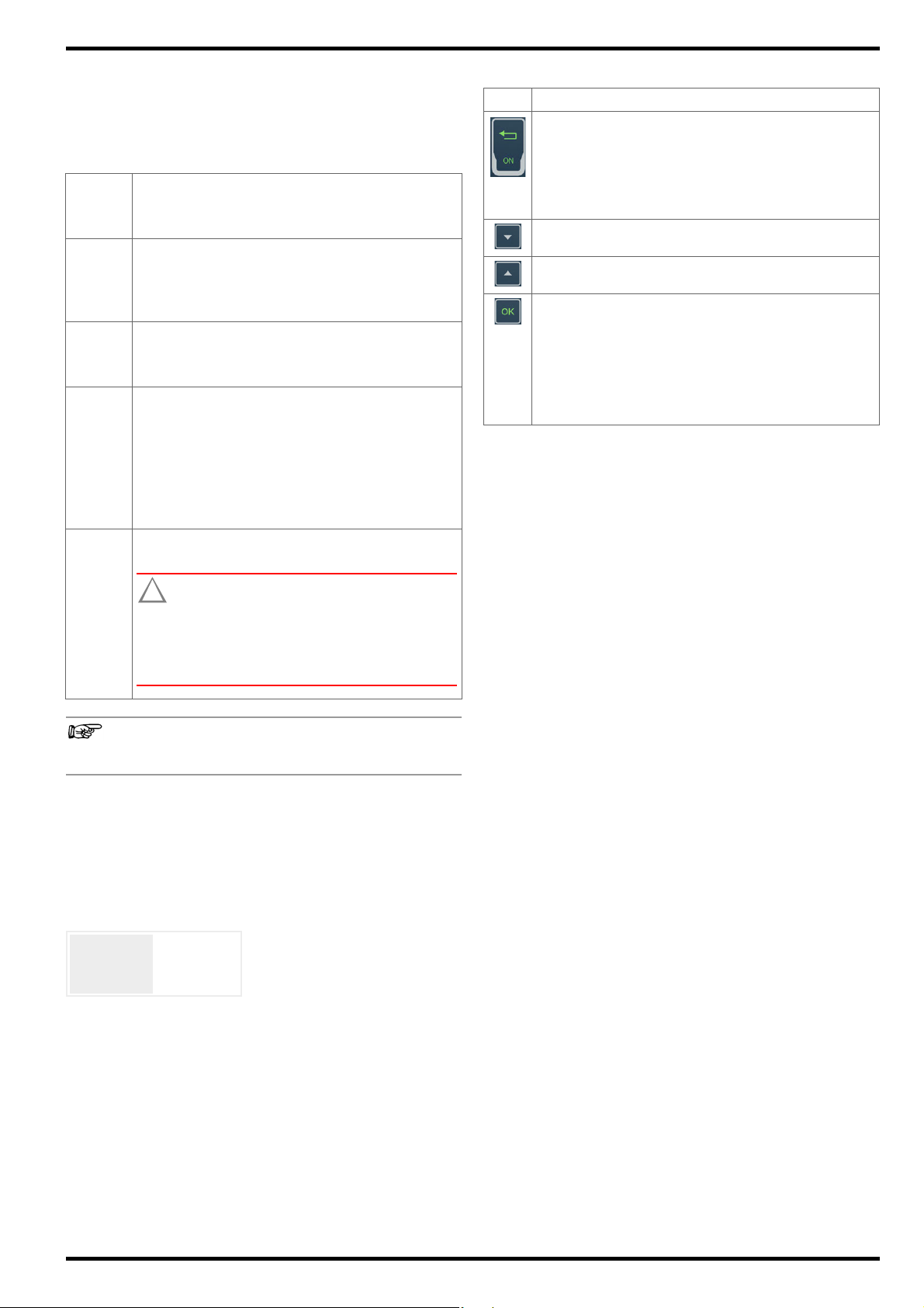
The following identifiers are used in this documentation:
Identifier Meaning
Safety information that must be complied with
Warning
Important information which must be
Important
Prerequisite A condition etc. which must be fulfilled
1. Procedural step Steps of a procedure which must be
Result Result of a procedural step
• Enumeration
– Enumeration
Figure 1: Caption
Table 1: Description of the content of a table
Footnote
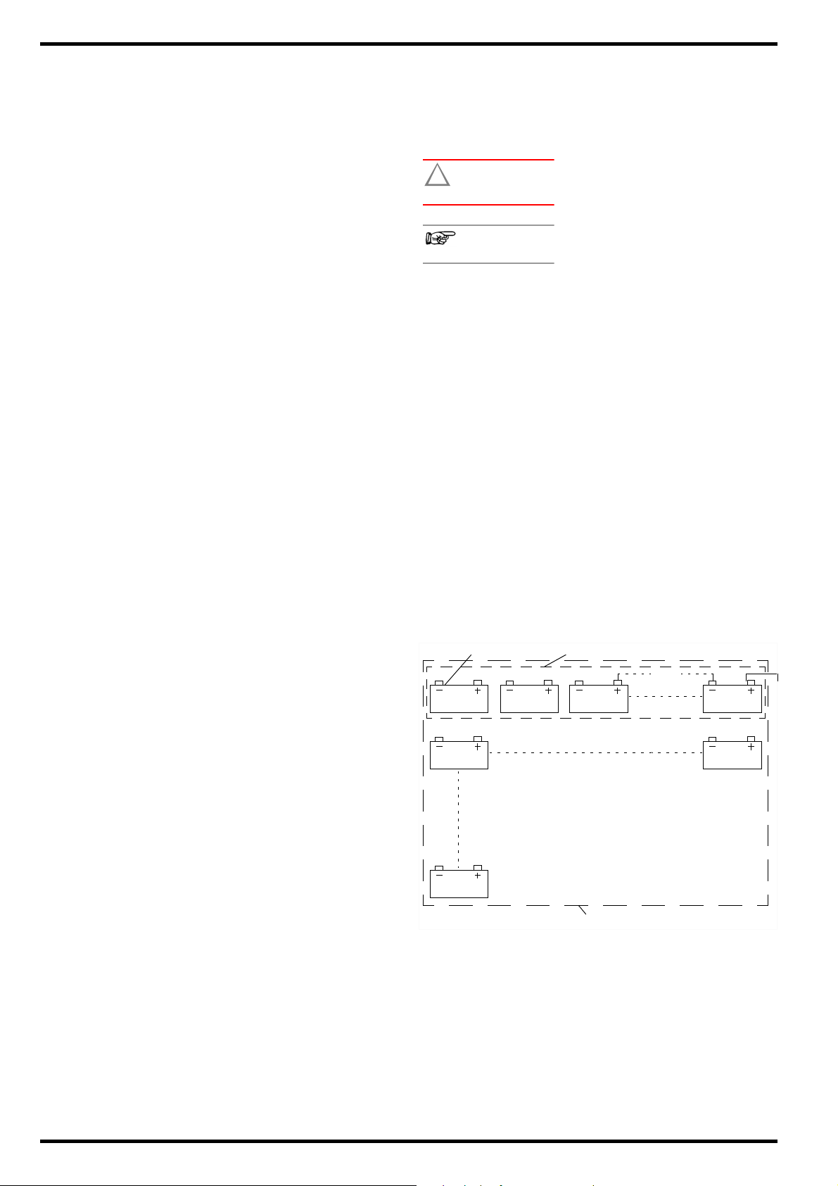
3.2 Definition of Terms
A block is the smallest unit. A group of two or more blocks is
called a battery. For example, this can involve several blocks connected in series (e.g. a traction battery) or a group of batteries
consisting of two or more blocks in a UPS system.
Measurements can be conducted for individual blocks or batteries. From an organizational standpoint, a device under test is
always set up in the battery tester as a battery which includes one
or more blocks which will be measured. And thus if you only want
to measure one block, set up a battery with just one block.
taken into consideration and complied
with
before a given action can be taken
completed in the specified order
Bullet lists
Description of the content of a figure
Comment
2
Figure 2: Example – Blocks and Battery within a System
Page 5
GMC-I Messtechnik GmbH METRACELL BT PRO
2
11
3
4
5
6
7
10
9
1
8
4 Getting Started
1. Read and adhere to the product documentation. In particular
observe all safety information in the documentation, on the
instrument and on the packaging.
“Safety Precautions”
“Important Information”
“Documentation”
2. Familiarize yourself with the battery tester.
“The Instrument” 3
“Operation”
“Menu and Functions”
3. Install BT PRO Manager software and familiarize yourself with
the program
4. Create a battery database 20.
5. Complete all required preparation in order to be able to perform measurements
6. Perform measurements
7. Evaluate your measurements “Viewing, Editing, Transferring
and Evaluating Measured Values”
7
18.
1
2
2
10
18.
30.
50.
5 The Instrument
5.1 Scope of Delivery
Please check for completeness.
1 METRACELL BT PRO
1 Rubber holster
4 1.2 V AA batteries
1Power pack
1 Set of multimeter test probes (KS29)
2 Alligator clips (KY95-3)
1 Set of Kelvin probes for 4-wire measurement (Z227D)
1 Carrying strap
1 Carrying case
1BTPRO Manager (battery tester management software)
1 Test report / factory calibration certificate
1 Condensed operating instructions
5.2 Optional Accessories
Some measurements necessitate optional accessories:
– AC/DC current clamp sensor
– CP1800 (Z204A) for measurements up to 1250 ADC or
– CP330 (Z202B) for measurements up to 300 A
– METRATHERM IR BASE temperature sensor (Z680A)
– Spring-loaded contact pins as replacement parts for the Kelvin
probes (Z227F)
Please contact our product support team for further information
on accessories
53.
DC
Values recorded by and stored at the DMA 35 portable density
meter from Anton Paar GmbH can be transferred to the battery
tester. A description of how to use the density meter with the
METRACELL BT PRO is included in these operating instructions
(
30). Please contact Anton Paar GmbH for any further infor-
mation concerning the DMA 35 density meter.
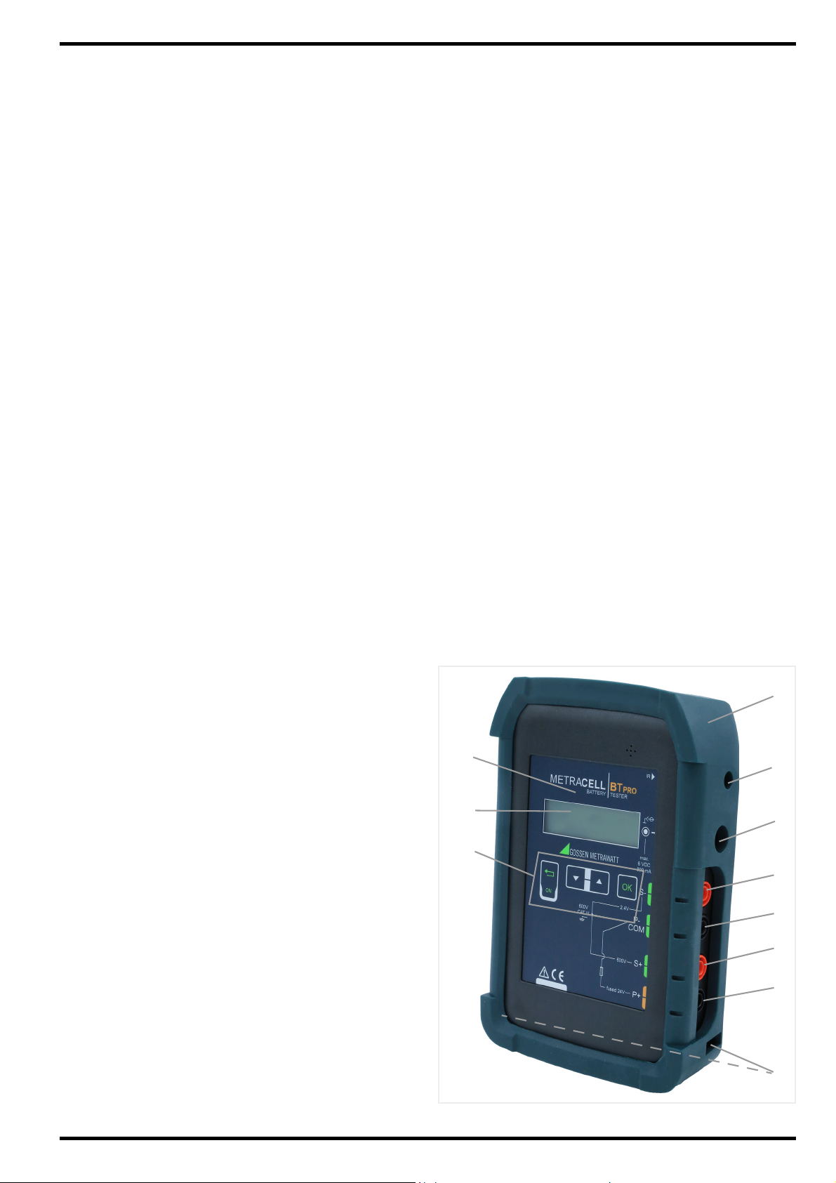
5.3 Instrument Overview
Front
Figure 3: Front Panel
3
Page 6
METRACELL BT PRO GMC-I Messtechnik GmbH
1
2
3
Attention!
!
!
Max.
6VDC
800 m
Symbols on the instrument and the included accessories:
No. Function
1 Rubber holster (removable)
2 Infrared interface
3 Charging socket (charging cable connection)
4 Measurement input S−
5 Measurement input P−/COM
6 Measurement input S+
7 Measurement input P+
8 Carrying strap eyelets
9 Function keys
10 Display
11 RFID reader
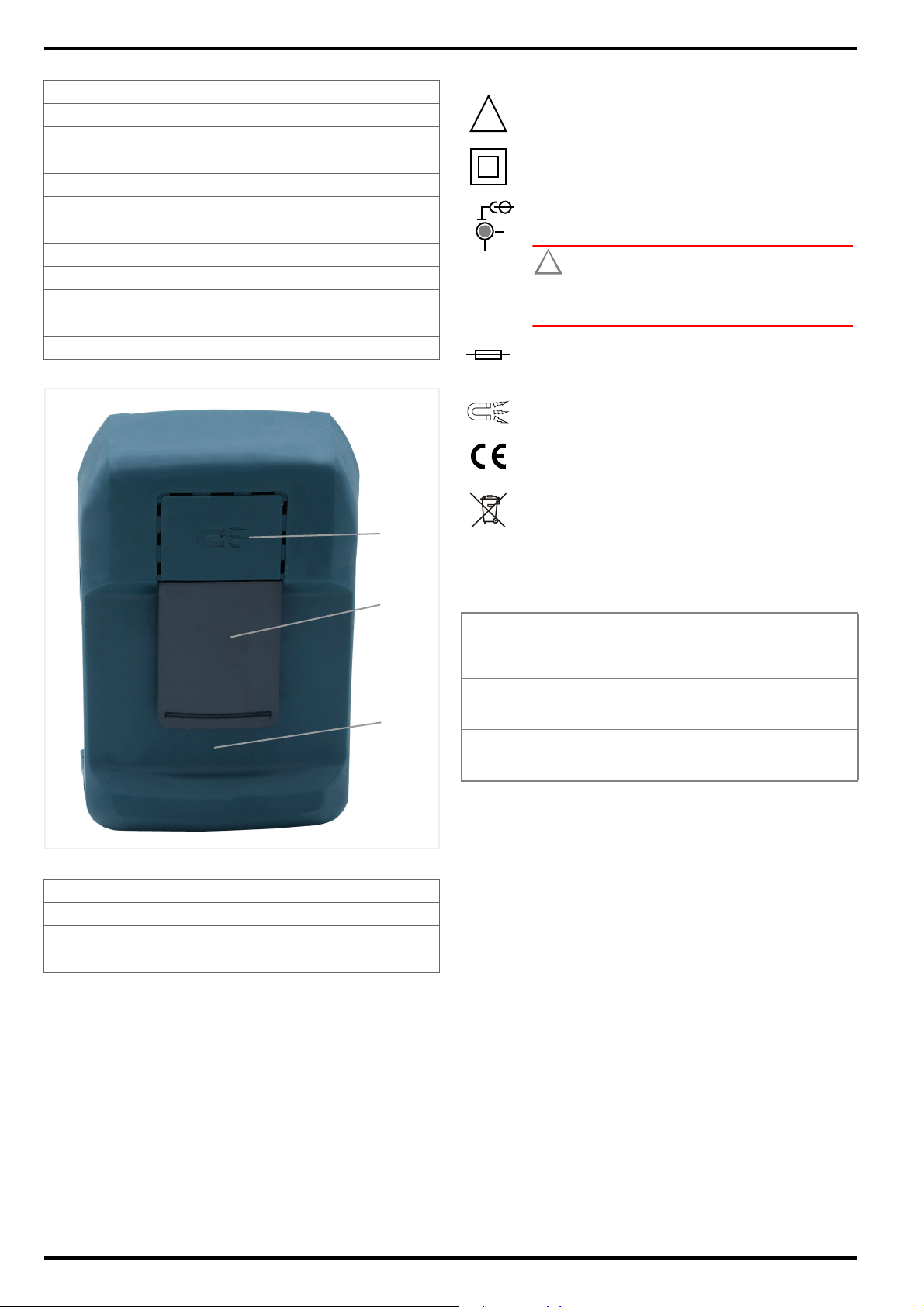
Back
IR
Infrared interface location
Warning concerning a point of danger
(attention, observe documentation!)
Double insulation (protection category II)
Charging socket location
( “Instrument Overview”
Attention!
Only rechargeable NiMH batteries may be inserted when the charger is connected.
Fuse
Static magnetic field
European conformity marking
3)
Figure 4: Back of Instrument
No. Function
1 Retaining magnet
2 Retaining clip
3 Battery compartment cover (underneath the holster)
The device may not be disposed of with household
trash “Returns and Environmentally Sound Disposal” 54.
5.4 Relevant Standards
The battery tester has been manufactured and tested in accordance with the following safety regulations:
IEC 61 010-1
EN 61 010-1
VDE 0411-1
EN 60 529
VDE 0470, part 1
DIN EN 61 326-1
VDE 0843-20-1
Safety requirements for electrical equipment
for measurement, control and laboratory use
–
General requirements
Test instruments and test procedures
Degrees of protection provided by enclosures
(IP code)
Electrical equipment for measurement, control and laboratory use – EMC requirements –
Part 1: General requirements
4
Page 7
GMC-I Messtechnik GmbH METRACELL BT PRO
Note
Attention!
!
<Date>
<Time>
BTpro
<Version>
5.5 Measurement Inputs
All measurement inputs are referenced to ground and reference
potential, P–/COM input. The measurement inputs are not electrically isolated from each other.
The measuring ranges depend on the respective measurement
inputs.
Measurement
input
S− Input for measuring DC voltage.
P−/COM Reference potential (ground potential) of all measure-
S+ Measurement input for direct and alternating voltage
P+ Current conducting cable to plus pole during resis-
Function
Measuring range: ±2450.00 mVDCResolution: 0.01 mV
Input impedance: > 10 M
Sensing lead to minus pole during resistance mea-
surement.
ment inputs.
Current conducting cable to minus pole during resistance measurement.
measurements.
Measuring
ranges: ±24.5000 V
±600.000 V
Input impedance: 1.6 M
±300.000 V
Sensing lead to plus pole during resistance measurement.
tance measurement.
Max. 24 V
Maximum test voltage must not exceed
24 V DC at input P+.
The instrument is damaged if this value is
exceed.
600 V CAT III refers to measurement inputs S+, S−
and P−/COM.
DC
Resolution: 0.1 mV
DC
Resolution: 1 mV
DC
Resolution: 10 mV
AC
5.6 LCD Display
All measured values, functions and settings can be observed at
the instrument’s display. As a rule, the display at the LCD panel
appears in two lines. Three and four-line displays are also used in
some cases, for example with measured values.
After switching the battery tester on, the initial display appears
including the instrument’s designation and the version, as well as
date and time.
Figure 5: Figure: Initial Display
After pressing any key while the initial display is shown, the battery
tester is switched to the main menu.
All other displays and information which appear at the instrument
depend on the previously selected function. The currently selected
function is always identified by a preceding arrow ->.
5.7 Function Keys / Navigation
Key Function
“Function” key
– Switch on and off ( 7)
– Press briefly: Return to next higher menu level or
cancel measurement
– Press and hold: End (
measurement
Scroll down key “▼”
Selection of menu items or digits in downward direction.
Scroll up key “▲”
Selection of menu items or digits in upward direction.
“OK” key
– Open menus
– Execute functions
– Confirm entries
– Select digits
– Proper termination of measurements
– Press and hold: repeat measurement (
30) or reactivate ( 30)
31)
5.8 RFID Reader
The display is surrounded by an RFID reader. If individual batteries
are equipped with an RFID tag (transponder), the tag can be
scanned before measurement, thus making it possible to subsequently assign the measurement data to the respective DUT automatically
125 kHz Technology
The RFID reader can only read RFID tags which use a frequency of
125 kHz. This technology offers several advantages:
• As one of the first RFID technologies, it’s widely used and easy
to obtain.
• It uses robust tags which are relatively insensitive to interfer-
ence from metals and liquids, which is crucial in battery envi-
ronments.
• Universal use (license-free ISM band)
• Minimal energy consumption (low-frequency long-wave band –
LF passive tags)
• Reading range: approx. 10 cm
• Small data transfer volumes with fast reading process (e.g.
only object ID as battery identification)
Reading RFID Tags
In order to read an RFID tag, hold the battery tester display 1 to
2 cm above the RFID tag. RF appears at display.
32.
5.9 Attachment Options
The battery tester provides acoustic feedback for all important
procedural steps, e.g. readiness to record measured values. Consequently, there’s no need to continuously observe the display.
In order to ensure freedom of movement, comfort and quick work
for the operator, the battery tester can be secured by means of
various retaining devices for the entire duration of measurement:
• Carrying strap:
The operator can use the carrying strap to suspend the battery
tester around his neck. The condensed operating instructions
include a description of how to attach the carrying strap.
• Retaining clip:
The operator can attach the battery tester to his belt with the
help of the retaining clip.
• Retaining magnet:
The battery tester can be attached to magnetic surfaces such
as battery cabinet doors with the retaining magnet.
5
Page 8
METRACELL BT PRO GMC-I Messtechnik GmbH
Note
Note
5.10 Technical Data
Power Supply Rechargeable NiMH batteries, 4 ea. 1.2 V type AA (recommended: Ansmann maxE 2500 mAh)
Input Impedance
Ambient
Conditions
Electrical Safety
Electromagnetic
Compatibility (EMC)
Mechanical
Design
Data Interfaces
Internal Memory Up to 300,000 data records
Measurement input S+: 1.6 M
Measurement input S-: > 10 M
Operating temperature: +5 ... +40 °C
Storage temperature: -20 ... +60 °C
Relative humidity: Max. 75%, no condensation allowed
Elevation: Max. 2000 m
Measuring category: 600 V CAT III
Pollution degree: 2
Protection category: II per IEC 61 010-1/EN 61010-1/VDE 0411-1
Fuse link: 1 ea. SIBA 600 V/10 A FF
Test Voltage: Test voltage at measuring connection P+ may not exceed 24 V
Interference emission: EN 61326-1:2013, class A
Interference immunity: EN 61 326-1:2013
EN 61326-2-1:2013
Protection: Housing: IP40
per DIN VDE 0470, part 1/EN 60 529
(protection against ingress of solid foreign objects:
1.0 mm dia., protection against ingress of
water: not protected)
Housing: Approx. 9.6 × 15.4 × 3.3 cm (W × H × D)
Weight: Approx. 0.45 kg (without rubber holster)
Display: LCD, monochrome, luminous
IrDA: Connection for DMA 35 density meter, version 3
RFID: Connection for RFID tag
®
Bluetooth
: Connection for PC, headset and DMA 35 density meter, version 4
DC
.
Technical data for the AC/DC current clamp sensors, the temperature sensor and the DMA 35 density meter can be found in the
respective product documentation.
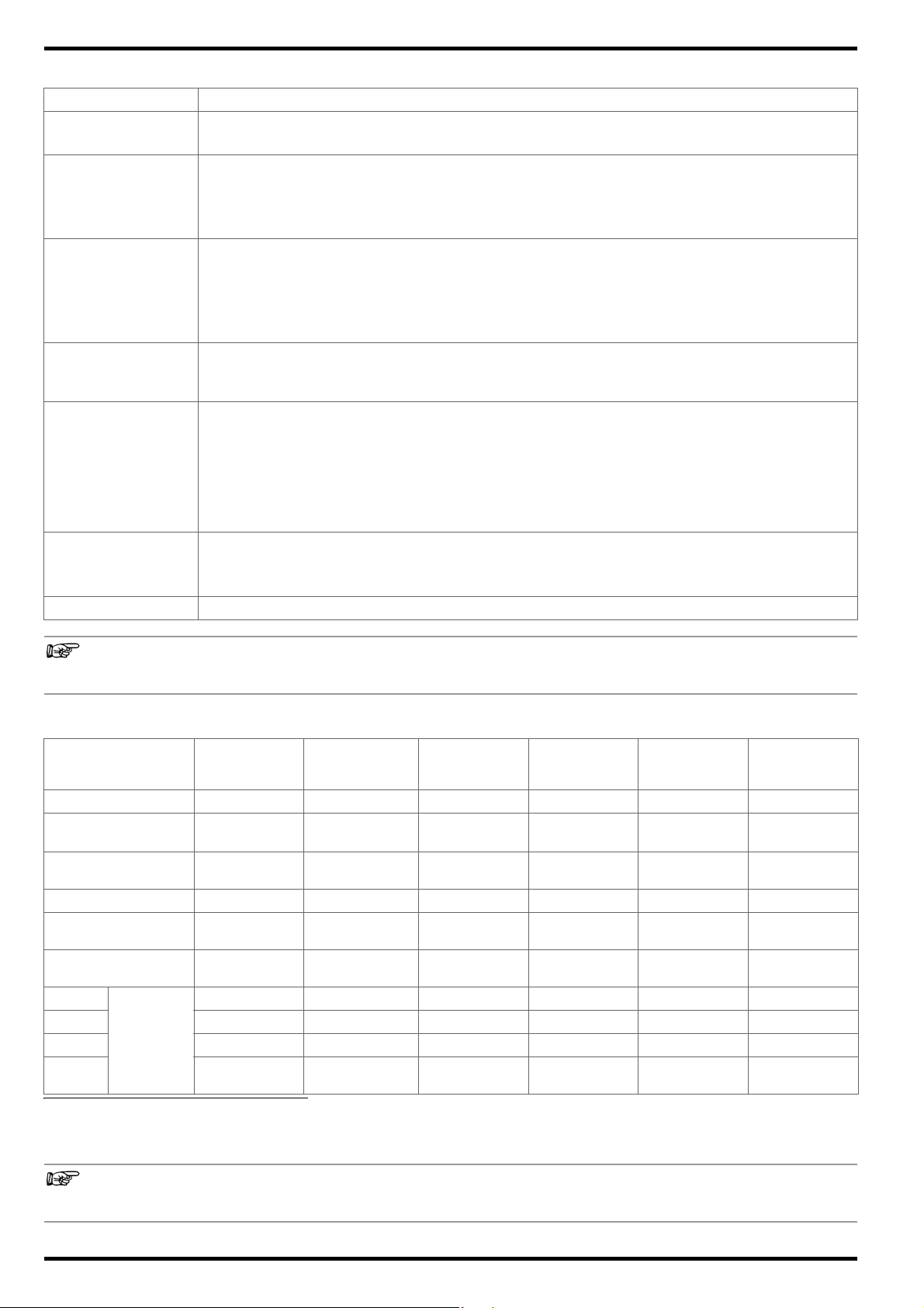
5.11 Characteristic Values
Measuring Function
Multimeter/
Connector
Measured Quantity V
Display Range
Measuring Range
-2450.00 …
+2450.00 mV
-2450.00 …
+2450.00 mV
DC
Multimeter/
Float/
Discharge/Charge
V
DC
-24.5000 …
+24.5000 V
-24.5000 …
+24.5000 V
Resolution 0.01 mV 0.1 mV 1 mV 10 mV 0.01 m 0.1 °C
Input Impedance /
Test Cu r r e n t
Intrinsic Uncertainty
S+
S− •••
P+ •
Measuring
connec-
tions
P−/
COM
1)
Only applicable if the temperature sensor is connected to the battery tester.
2)
Within a frequency range of 45 to 500 Hz.
>10M 1.6 M 1.6 M 1.6 M l
±(0.05%
rdg. + 10 d)
±(0.05%
rdg. + 10 d)
• •••
• • ••••
Multimeter/
Interval U/
Internal U+I
V
DC
-600.000 …
+600.000 V
-600.000 …
+600.000 V
±(0.05%
rdg.+ 50 d)
Multimeter Resistance Temperature
V
AC
-300.000 …
+300.000 V
-300.000 …
+300.000 V
±(2.0%
rdg. + 10 d)
2)
Rel + R
ct
00.00 …
1000.00 m
°C
-230.0 …
+230.0 °C
00.10 …
1000.00 m
approx. 2 A > 10 M
p
±(3.0%
rdg. + 8 d)
1)
The characteristic values of the AC/DC current clamp sensors and the DMA 35 density meter, as well as additional characteristic
values for the temperature sensor, can be found in the respective product documentation.
6
Page 9
GMC-I Messtechnik GmbH METRACELL BT PRO
Attention!
!
Attention!
!
Note
Attention!
!
Attention!
!
Note
6 Operation
6.1 Power Supply (rechargeable batteries)
Battery Operation
The battery tester is operated with rechargeable NiMH batteries.
Pre-charged batteries are shipped loose. You have already
inserted the batteries during initial startup (
ating instructions).
Operating time is approximately 10 hours when the batteries are
fully charged. A warning is generated when battery voltage drops
to below 4.8 V. The battery tester can be operated for approximately 1 more hour after this warning is generated.
Leaking batteries can damage the device.
Check the batteries at short, regular intervals and after long
periods of storage.
Charging Process
It takes about 3½ hours to charge the batteries.
Damage to the batteries or the instrument.
When charging, use only:
- The included rechargeable batteries or the
batteries specified in the technical data
- The included charger
Always connect the battery charger to the
battery tester before connecting the charger
to the electrical outlet.
condensed oper-
The battery tester must be switched off.
All measurement cables and accessories must be removed
from the battery tester.
1. Remove the holster from the battery tester: Press against the
bottom of the holster at the front and push it back and off of
the battery tester. As soon as the lower part of the battery tester is exposed, pull the instrument completely out of the holster.
2. Place the battery tester face down on a stable surface.
3. Loosen and remove the screw from the battery compartment
cover.
4. Unlock and remove the battery compartment cover.
5. Remove any batteries from the battery compartment.
6. Insert 4 approved rechargeable batteries into the battery compartment, making sure that the plus and minus poles match up
with the provided polarity symbols.
Only the included batteries or those specified in the technical data ( 6) may be inserted and used.
7. Place the battery compartment cover onto the battery compartment and press it until it audibly clicks into place.
8. Secure the battery compartment cover with the screw.
9. Pull the holster back over the battery tester: Observe the cutouts in the holster for the front panel and the connections.
Push the battery tester into the holster at the top first as far as
it will go. Then press on the front at the bottom until the battery
tester is fully reinserted into the holster.
The batteries have now been inserted. The battery tester can
be used.
Do not switch the battery tester on during charging. The
battery tester may not be operated during charging and is
switched off automatically after 3 seconds.
The battery tester is switched off.
4 NiMH batteries are inserted
(see section on “Replacing the Batteries”
on inserting batteries).
All measurement cables and accessories must be removed
from the battery tester.
1. Insert the charger’s connector plug into the battery tester’s
charging socket “Instrument Overview”
2. Connect the charger to the 230 V mains outlet.
The batteries in the battery tester are charged.
3. Wait until the charging process has been completed.
It takes about 3½ hours to fully charge the batteries.
4. Unplug the charger from the electrical outlet.
5. Remove the connector plug from the battery tester’s charging
socket.
The batteries are charged. The battery tester can now be
used.
Replacing the Batteries
You can replace the batteries if necessary.
7 for information
3.
6.2 Switching the Instrument On/Off
Switching the Instrument On
1. Press and hold the Function key for approximately 2 seconds.
The initial display appears with the instrument’s designation
and version, as well as date and time ( “LCD Display”
2. Press any key.
The main menu appears at the display. The battery tester can
now be used.
Switching the Battery Tester Off
Normally, the battery tester is switched off manually. If the battery
tester has not been used for more than 10 minutes, it’s switched
off automatically.
1. Select POWER OFF in the main menu with the help of the ▼
key.
2. Press the OK key.
The display goes blank. The battery tester has been switched
off.
The battery tester can also be switched off by pressing the
Function key. The key must be pressed and held for approximately 10 seconds to this end.
However, it’s preferable to switch the instrument off using
the SWITCH OFF function.
5).
Risk of injury due to contact with dangerous voltages.
Only use the battery tester when the battery compartment
cover is inserted and firmly screwed into place.
Required tools: Philips screwdriver
7
Page 10

METRACELL BT PRO GMC-I Messtechnik GmbH
Note
Note
Note
Note
6.3 System Settings
You can enter basic settings to the battery tester.
Setting Date and Time
Switch back and forth between standard time and daylight
savings time manually. The battery tester is not equipped
with an automatic time change function.
Although the battery tester can be paired with several
devices via Bluetooth
eral devices via Bluetooth® is not possible.
®
Bluetooth
needed.
connections can be terminated when they’re no longer
®
, simultaneous operation with sev-
1. Switch the battery tester on 7.
2. Press the OK key.
The main menu appears.
3. Select SETTINGS from the main menu
using the ▼▲ keys.
4. Press the OK key.
The SETTINGS menu is displayed.
5. Select SYSTEM using the ▼▲ keys.
6. Press the OK key.
The SYSTEM menu is displayed.
7. Select SET TIME&DATE using the ▼▲ keys.
8. Press the OK key.
The SET TIME&DATE menu is displayed. The cursor is positioned
at the first digit of the date display (dd.mm.yy: dd = day, mm =
month and yy = year).
9. Use the ▼▲ keys to enter the first digit of the two-digit display
for the current day.
10. Press the OK key to move to the second digit.
11. Repeat steps 9. and 10. until the date has been completely
entered.
After entering and confirming the last digit for the year, the cursor jumps to the first digit of the time display (ss:mm:hh: ss =
second, mm = minute and hh = hour)
12. Set the digits for time in the same way as described for setting
the date.
After entering the last digit for current time, your settings are
saved. The SYSTEM menu is displayed.
Date and time have been set.
Language Selection
Device language can be set to either English or German.
1. Switch the battery tester on
2. Press the OK key.
The main menu appears.
3. Select SETTINGS from the main menu
using the ▼▲ keys.
4. Press the OK key.
The SETTINGS menu is displayed.
5. Select SYSTEM using the ▼▲ keys.
6. Press the OK key.
The SYSTEM menu is displayed.
7. Select SEL. LANGUAGE using the ▼▲ keys.
8. Press the OK key.
The SEL. LANGUAGE menu is displayed.
9. Select the desired language using the ▼▲ keys.
10. Press the OK key.
The device language is changed.
7.
6.4 Establishing and Terminating Wireless Connections
The battery tester can be wirelessly connected to various devices:
• To the DMA 35 density meter from Anton Paar GmbH
– DMA 35 version 3 via infrared “DMA35 Measurement
(IrDA)”
49
– DMA 35 version 4 via Bluetooth
ment (BT)”
• To a PC in order to view, evaluate and save measurement data
“Saving Measured Values to a PC (data backup)”
• To a headset for improved audibility of signals generated by the
instrument “Establishing and Testing a Bluetooth® Connection with a Headset”
49
8
®
“DMA35 Measure-
50
In case of connection problems, it may be helpful to terminate (
references to specific sections above).
Establishing and Testing a Bluetooth
Acoustic signals are used to confirm various actions before, during
and after a measuring procedure, as well as certain instrument
reactions.
The instrument can be paired with a headset, making it possible to
better hear these signals in noisy work environments. The connection can be checked in advance with a test signal.
Read and adhere to the documentation included with your
headset.
The headset supports Bluetooth
1. Switch the battery tester on
2. Press the OK key.
The main menu appears.
3. Select SETTINGS from the main menu
using the ▼▲ keys.
4. Press the OK key.
The SETTINGS menu is displayed.
5. Select BT-SETTINGS using the ▼▲ keys.
The BT-SETTINGS menu is displayed.
6. Select LINK HEADSET using the ▼▲ keys.
7. Press the OK key.
8. The PUT HEADSET IN PAIRING MODE -> prompt appears.
9. Set the headset to pairing mode. Read the documentation
included with your headset to find out how.
10. Position the headset close to the battery tester.
11. Acknowledge the PUT HEADSET IN PAIRING MODE -> prompt by
pressing the OK key.
BT PAIRING: SEARCH HEADSET! appears at the display.
12. The headset and the battery tester are connected to each
other. Pairing progress is displayed as a percentage. As soon
as the devices are successfully connected, SUCCESSFUL!
appears at the display.
13. Put on the headset.
14. Press the OK key.
The BT-SETTINGS menu is displayed.
15. Press the Function key.
The main menu appears.
16. Select SETTINGS from the main menu using the ▼▲ keys.
17. Press the OK key.
The SETTINGS menu is displayed.
18. Select SYSTEM using the ▼▲ keys.
19. Press the OK key.
The SYSTEM menu is displayed.
20. Select TEST HEADSET using the
21. Press the OK key.
A test signal is played back at the headset.
9) and reestablish Bluetooth
®
Connection with a Headset
®
profile “HSP”.
7.
▼▲ keys.
®
connections (see
8
Page 11

GMC-I Messtechnik GmbH METRACELL BT PRO
Terminating the Bluetooth® Connection
All paired devices are disconnected when the Bluetooth
tion is terminated. It’s not possible to disconnect individual
devices.
1. Switch the battery tester on 7.
2. Press the OK key.
The main menu appears.
3. Select SETTINGS from the main menu
using the ▼▲ keys.
4. Press the OK key.
The SETTINGS menu is displayed.
5. Select BT-SETTINGS using the ▼▲ keys.
The BT-SETTINGS menu is displayed.
6. Select REM. PAIRINGS using the ▼▲ keys.
7. Press the OK key.
The DO YOU REALLY WANT TO DELETE? prompt appears.
8. Press the OK key.
DELETING DATA! PLEASE WAIT appears briefly at the display.
REM. PAIRINGS appears at the display.
Bluetooth
minated.
®
connection to all paired devices has now been ter-
®
connec-
6.5 Testing the RFID Reader
The RFID reader can be tested ( 5).
A compatible RFID tag (125 kHz) is available.
1. Switch the battery tester on
2. Press the OK key.
The main menu appears.
3. Select SETTINGS from the main menu
using the ▼▲ keys.
4. Press the OK key.
The SETTINGS menu is displayed.
5. Select SYSTEM using the ▼▲ keys.
6. Press the OK key.
The SYSTEM menu is displayed.
7. Select TEST TRANSP. using the ▼ key.
8. Press the OK key.
WAITING FOR RFID – – – – –> ( ) <– – – – – appears at the display.
Furthermore, a repetitive acoustic signal indicates readiness to
read.
9. Hold the battery tester’s RFID reader roughly 1 to 2 cm above
the RFID tag.
The RFID tag is read. The RFID tag’s number appears at the
display.
7.
Refer to section on “Performing Measurements”
assign RFID tags to DUTs and read them out during measurement.
30 on how to
9
Page 12
METRACELL BT PRO GMC-I Messtechnik GmbH
Initial
Display
2 sec.
ON
OK
ON
ON
OK
ON
OK
ON
OK
ON
OK
OK
ON
OK
OK
ON
OK
OK
ON
OK
OK
ON
OK
A
OK
OK
ON
OK
ON
OK
ON
OK
OK
ON
OK
OK
ON
OK
OK
ON
OK
OK
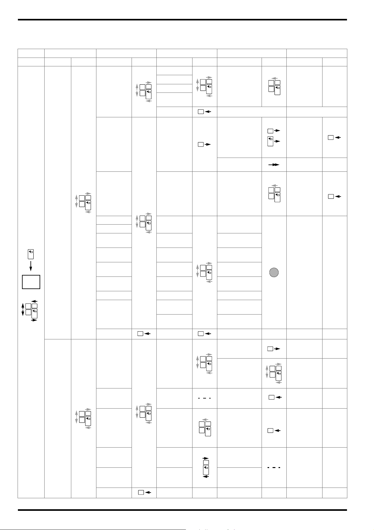
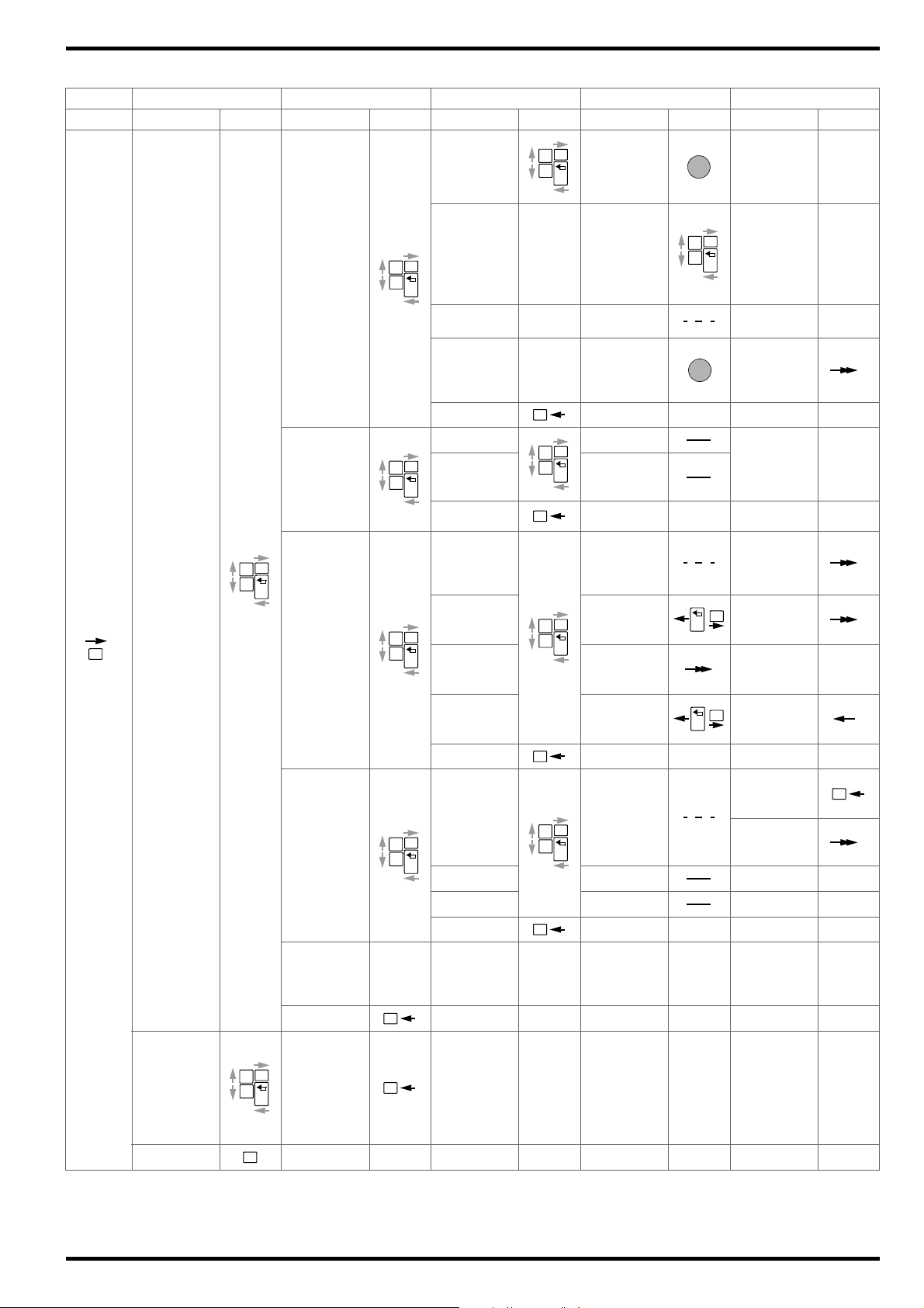
7 Menu and Functions
7.1 Overview
On Main Menu Level 1st Submenu Level 2nd Submenu Level 3rd Submenu Level 4th Submenu Level
Start Display Keys Display A Keys Display Keys Display Keys Display Keys
Start measurement
(short tone),
end measurement
(short tone), display value
Start measurement
(short tone),
end measurement
(short tone),
display value
WAITING FOR
DMA35
Battery database
display,
brief tone indicates RFID readiness to read
BATTERY: 0000
BLOCKS: 0000
MIN: 00 0 0
[U/M]
MAX: 00 0 0
[U/M]
CLAMP A: 0000
CLAMP mV: 0000
Display measured values (see
key)
Display measured value evaluation
End measured value
recording,
return to
MULTIMETER
display
WANT TO QUIT
WITH SAVING?
WANT TO QUIT
WITHOUT
SAVING?
In case of
manual selection, return to
display.
In case of
RFID, display
read result.
Repeat measurement
View evaluation via all
keys, then automatic return
For RFID
MEASUREMENT
2.45 V DC (S-)
24.5 V DC (S+)
MULTIMETER
600 V DC (S+)
300 V AC (S+)
QUIT
FLOAT START
DISCHARGE SELECT.BATT
CHARGE
RESISTANCE
TEMPERATURE
CONNECTOR
INTERVAL U
INTERVAL U+I
AREA: XXXX AREA: 0000
BATTERY:
XXXX
BLOCKS
XXXX*
MIN: XX.XXX
[U/M]
MAX: XX:XXX
[U/M]
DMA35 (IrDA) INT [s]: XXXX** INT [s]: 0000
CLAMP A:
DMA35 (BT)
XXXX ***
CLAMP mV:
XXXX ***
QUIT QUIT
Display of
measurement
SHOW DATA
with indication of measurement type,
date, time etc.
10
DATA
MENU
EXPORT (CSV)
SHOW
BAT-DEF
CLEAR DATA
CLEAR
BAT-DEF
QUIT
BT CSV
EXPORT
(CONNECT)
Battery database display,
brief tone indicates RFID
readiness to
read
DO YOU
REALLY WANT
TO DELETE?
DO YOU
REALLY WANT
TO DELETE?
DEVICE PAIRED?
EXPORT TARGET
OK?
In case of manual
selection, return
to display.
In case of RFID,
display read result.
DELETING
DATA!
PLEASE WAIT!
DELETING
DATA!
PLEASE WAIT!
For RFID
Brief tone
indicates
deletion,
return to
CLEAR DATA/
BATT. display
Page 13
GMC-I Messtechnik GmbH METRACELL BT PRO
OK
ON
OK
ON
OK
ON
OK
A
ON
OK
B
OK
ON
OK
ON
OK
OK
ON
OK
ON
OK
ONOKON
OK
OK
ON
OK
ON
OK
OK
OK
OK
ON
OK
OK
OK
(continued)
On Main Menu Level 1st Submenu Level 2nd Submenu Level 3rd Submenu Level 4th Submenu Level
Start Display Keys Display A Keys Display Keys Display Keys Display Keys
SETTINGS
INFO
POWER OFF
SYSTEM
MEASUREMENTS
BT-SETTINGS
CSV-EXPORT
FACTORY
ONLY
QUIT
VERSION:
VX.XX
ENTRIES:
XXX%
MEMORY:
XXX%
BATTERY:
XXX%
SET
TIME&DATE
SEL. LANGUAGE
DATE: XX.XX.X
TIME:
XX:XX:XX
ENGLISH
DEUTSCH
TEST HEADSET
Read out test
signal
WAITING
TEST TRANSP.
FOR RFID
-----> ( ) <----
-
QUIT
POLARITY ON POLARITY ON
POLARITY OFF POLARITY OFF
QUIT
BT
LINK
COMPUTER
PAIRING:
WAITING FOR
PC
PUT HEADSET
LINK HEADSET
IN PAIRING
MODE ->
LINK DMA35
V4
REM.
PAIRINGS
PLEASE DIS-
COVER BTpro
WITH DMA35
DO YOU RE-
ALLY WANT TO
DELETE?
QUIT
EXPORT
TARGET
SCANNING
FOR
BT DEVICES.
FILENA. FIXED FILENA. FIXED
FILEN. UNIQ. FILEN. UNIQ.
QUIT
FACTORY USE
ONLY
PASSWORD:
XXXXX
Menu is displayed in selected language,
return to
LANGUAGE
SEL.
display
WAITING FOR
RFID
<RFID
Number>
Brief tone signals selection,
display remains in
menu
List with
all detected
BT devices is
displayed.
BT PAIRING:
SEARCH
HEADSET
DELETING
DATA!
PLEASE WAIT!
NO BT
DEVICES
FOUND
Detected BT
devices are
listed
11
Page 14
METRACELL BT PRO GMC-I Messtechnik GmbH
=
=
OK
ON
=
A
=OK=
=
ON
=
B
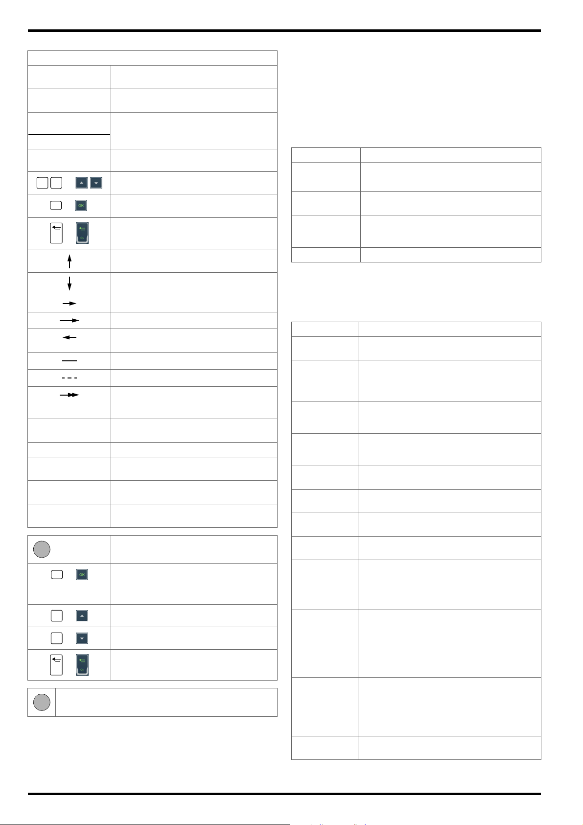
7.2 Display Menu
General Key
-> MEASUREMENT
DATA
DELETING DATA
Display menu/function,
the arrow indicates the selected function.
Feedback or information after action
PLEASE WAIT
BLOCK 12.2500V
0004/4
Display measured value (example)
Display measured value evaluation
AN:0001 BN:0010
Descriptive text Explanation of measured value, parameter
and other displays
Scroll within menu levels and functions.
Start function,
submenu selection
Switch on,
termination of an action currently being executed
Move up one view in the menu.
The initial display appears after switching the battery tester on
(
7). The main menu is then displayed after pressing any key.
If you’re already in a submenu, press the FUNCTION key repeatedly
until the display is returned to the main menu.
This is the central menu from which all other hierarchically subordinate menus and functions can be accessed. All main menu functions can be selected with the help of the ▼▲ keys.
Table 10: List of Functions Available in the Main Menu
Function Description
MEASUREMENT Available measuring functions
DATA MENU Data management functions
12
15
SETTINGS Parameter settings for system, measure-
ments and data transfer
16
INFO Information concerning firmware version, bat-
tery charge level and memory occupancy
17
POWER OFF Switch off the battery tester
7.
Move down one view in the menu.
Jump to submenu level (press briefly).
Jump to submenu level (press and hold).
Jump back to higher menu level (initial position).
Remains at current position.
No action required.
Further action and displays depend on
systems to be linked or downstream systems.
0 Currently selected digit (display with black
background).
X Placeholder for one digit.
* Parameter not for measuring functions
INTERVAL U and INTERVAL U+I
** Parameters only for measuring functions
INTERVAL U and INTERVAL U+I
*** Parameters only for measuring functions
INTERVAL U and INTERVAL U+I
Set/select special key assignments for
parameters
Cursor for selecting the digit to be
changed (inverted cursor), storage takes
place after selection of the last digit, then
return to higher menu level
Increase digit
Decrease digit
Cancel entry/selection of digits without
saving, return to higher menu level
RFID tags must be held roughly 1 to 2 cm above the display
7.3 Measurement Menu
Select MEASUREMENT in the main menu and then press the OK
key in order to open the menu.
Table 11: List of Functions Available in the MEASUREMENT Menu
Measurement Description
MULTIMETER DC and AC voltage measurements without
FLOAT Periodic measurement of block voltages.
DISCHARGE Multiple measurement of block voltages at
CHARGE Multiple measurement of block voltages at
RESISTANCE Periodic measurement of the internal resis-
TEMPERATURE Measurement of block temperature with an IR
CONNECTOR Measurement of voltage drop to determine
INTERVAL U Measurement of the voltage of a battery at any
INTERVAL U + I Measurement of the voltage and current of a
DMA 35 (IrDA) Measurement of acid density and electrolyte
DMA 35 (BT) Measurement of acid density and electrolyte
QUIT Exit the MEASUREMENT menu and return to the
storing measured values
This measurement is used for quarterly recording of float voltage, for example in UPS systems.
short intervals during discharging (capacitance
test)
short intervals during charging (capacitance
test)
tance of the blocks
temperature sensor
connector loss between blocks
desired time intervals (voltage curve)
battery at any desired time intervals (voltage
and current curves)
Example: Recording of discharge current
during discharging.
temperature within a block.
Measurements are performed with the DMA 35
density meter (version 3) from Anton Paar
GmbH. Data are transferred from the sensor to
the battery tester via infrared (Infrared Data Association – IrDA).
temperature within a block.
Measurements are performed with the DMA 35
density meter (version 4) from Anton Paar
GmbH. Measured values are transferred from
the sensor to the battery tester via Bluetooth
®
main menu.
12
Page 15
GMC-I Messtechnik GmbH METRACELL BT PRO
Note
Temperature
The required parameters for the device under test must be
defined before starting a measurement. Use the battery
database to this end ( “Performing Measurements”
30
and “Transferring the Battery Database to the Battery
Tester”
23).
Manual entries should only be made in exceptional cases.
Multimeter
Select the MEASUREMENT MULTIMETER function sequence via
the main menu and press the OK key in order to open the menu.
Table 12: Possible Measuring Ranges for MULTIMETER Measure-
ment
Measuring
Range
2.45 V
DC
24.5 V
DC
600 V
DC
300 V
AC
Description
(S–) Measuring range selection for direct voltage mea-
surement via measuring socket S–
(S+) Measuring range selection for direct voltage mea-
surement via measuring socket S+
(S+) Measuring range selection for direct voltage mea-
surement via measuring socket S+
(S+) Measuring range selection for alternating voltage
measurement via measuring socket S+
QUIT Return to MEASUREMENT menu
Float, Discharge, Charge and Resistance
In order to open the menu, select one of the following function
sequences from the main menu:
MEASUREMENT FLOAT or MEASUREMENT
DISCHARGE or MEASUREMENT CHARGE or MEASUREMENT
RESISTANCE, and then press the OK key.
Table 13: Parameters and Functions for the FLOAT, DISCHARGE,
CHARGE and RESISTANCE Measurements
Function/
Setting
Description
START Measurement is started after selecting or en-
tering the battery parameters.
SELECT.BATT The menu for selecting and loading a stored
battery database is accessed via this function.
If a database exists, the stored data records
appear.
AREA: XXXX Manual assignment of a unique four-digit
number for the location of the battery system
BATTERY: XXXX Manual assignment of a unique four-digit
number as a designation of the battery in the
battery system
BLOCKS:XXXX Manual assignment a unique four-digit num-
ber identifying the number of blocks within the
battery
MIN: XX.XXX V Manual measuring range setting: lower volt-
age limit value
MAX: XX.XXX V Manual measuring range setting: upper volt-
age limit value
(max. +24.50 V)
QUIT Return to MEASUREMENT menu
Select the MEASUREMENT TEMPERATURE function sequence
via the main menu and press the OK key in order to open the menu.
Table 14: Parameters and Functions for the TEMPERATURE Mea-
surement
Function/
Setting
Description
START Measurement is started after selecting or en-
tering the battery parameters.
SELECT.BATT The menu for selecting and loading a stored
battery database is accessed via this function.
If a database exists, the stored data records
appear.
AREA: XXXX Manual assignment of a unique four-digit
number for the location of the battery system
BATTERY: XXXX Manual assignment of a unique four-digit
number as a designation of the battery in the
battery system
BLOCKS:XXXX Manual assignment a unique four-digit num-
ber identifying the number of blocks within the
battery
MIN: XXXX.X C Manual measuring range setting: lower tem-
perature limit value
(max. –230 °C)
MAX: XXXX.X C Manual measuring range setting: upper tem-
perature limit value
(max. +230 °C)
QUIT Return to MEASUREMENT menu
Start / Battery Parameters Menu for Connector Measurement
Select the MEASUREMENT CONNECTOR function sequence via
the main menu and press the OK key in order to open the menu.
Table 15: Parameters and Functions for the CONNECTOR Mea-
surement
Function/
Setting
Description
START Measurement is started after selecting or en-
tering the battery parameters.
SELECT.BATT The menu for selecting and loading a stored
battery database is accessed via this function.
If a database exists, the stored data records
appear.
AREA: XXXX Manual assignment of a unique four-digit
number for the location of the battery system
BATTERY: XXXX Manual assignment of a unique four-digit
number as a designation of the battery in the
battery system
BLOCKS:XXXX Manual assignment a unique four-digit num-
ber identifying the number of blocks within the
battery
MIN: XXXX.X mV Manual measuring range setting: lower volt-
age limit value
MAX: XXXX.X mV Manual measuring range setting: upper volt-
age limit value
(max. +2400.0 mV)
QUIT Return to MEASUREMENT menu
13
Page 16
METRACELL BT PRO GMC-I Messtechnik GmbH
Note
Note
Note
Note
Start / Battery Parameters Menu for Interval U Measurement
Select the MEASUREMENT INTERVAL U function sequence via
the main menu and press the OK key in order to open the menu.
Table 16: Parameters and Functions for the INTERVAL U Mea-
surement
Function/
Setting
START Measurement is started after selecting or en-
SELECT.BATT The menu for selecting and loading a stored
AREA: XXXX Manual assignment of a unique four-digit
BATTERY: XXXX Manual assignment of a unique four-digit
INT [s]: XXXX Manually adjustable time interval (in seconds)
MIN: XXX.XX V Manual measuring range setting: lower volt-
MAX: XXX.XX V Measuring range setting: upper voltage limit
QUIT Return to MEASUREMENT menu
Interval U + I
Select the MEASUREMENT INTERVAL U+I function sequence via
the main menu and press the OK key in order to open the menu.
Table 17: Parameters and Functions for INTERVAL U+I Measure-
Function/
Setting
START Measurement is started after selecting or en-
SELECT.BATT The menu for selecting and loading a stored
AREA: XXXX Manual assignment of a unique four-digit
BATTERY: XXXX Manual assignment of a unique four-digit
INT [s]: XXXX Manually adjustable time interval (in seconds)
Description
tering the battery parameters.
battery database is accessed via this function.
If a database exists, the stored data records
appear.
number for the location of the battery system
number as a designation of the battery in the
battery system
for recording the measured value.
(min. 1 second)
age limit value
Same as discharge cut-off voltage. If
the limit value is fallen short of, the
instrument generates an acoustic signal at regular intervals. This indicates
that the discharging process has been
completed and measurement can be
ended.
value
Same as charge cut-off voltage. If the
limit value is exceeded, the instrument
generates an acoustic signal at regular
intervals. This indicates that the
charging process has been completed
and measurement can be ended.
(max. +600 V)
ments
Description
tering the battery parameters.
battery database is accessed via this function.
If a database exists, the stored data records
appear.
number for the location of the battery system
number as a designation of the battery in the
battery system
for recording the measured value.
(min. 1 second)
Function/
Setting
MIN: XXX.XX V Manual measuring range setting: lower volt-
MAX: XXX.XX V Manual measuring range setting: upper volt-
CLAMP A: XXXX Manual measuring range setting: Current
CLAMP mV: XXXX Manual measuring range setting: Voltage
QUIT Return to MEASUREMENT menu
DMA35 (IrDA and Bluetooth
Select the MEASUREMENT DMA35 (IrDA) or DMA35 (BT) function sequence via the main menu and then press the OK key in order
to open the menu.
Table 18: Parameters and Functions for the DMA35 (IrDA) and
Function/
Setting
START Measurement is started after selecting or en-
SELECT.BATT The menu for selecting and loading a stored
AREA: XXXX Manual assignment of a unique four-digit
BATTERY: XXXX Manual assignment of a unique four-digit
BLOCKS:XXXX Manual assignment a unique four-digit num-
MIN: X.XXXX Manual measuring range setting: lower limit
MAX: X.XXXX Manual measuring range setting: upper limit
QUIT Return to MEASUREMENT menu
Description
age limit value
Same as discharge cut-off voltage. If
the limit value is fallen short of, the
instrument generates an acoustic signal at regular intervals. This indicates
that the discharging process has been
completed and measurement can be
ended.
age limit value
Same as charge cut-off voltage. If the
limit value is exceeded, the instrument
generates an acoustic signal at regular
intervals. This indicates that the
charging process has been completed
and measurement can be ended.
(max. +600 V)
value of the transformation ratio of the current
clamp
value of the transformation ratio of the current
clamp
®
)
DMA35 (BT) Measurements
Description
tering the battery parameters.
battery database is accessed via this function.
If a database exists, the stored data records
appear.
number for the location of the battery system
number as a designation of the battery in the
battery system
ber identifying the number of blocks within the
battery
value for acid density
value for acid density
14
Page 17
GMC-I Messtechnik GmbH METRACELL BT PRO
Note
7.4 Data Menu
Select DATA MENU in the main menu and then press the OK key in
order to open the menu.
Table 19: Functions in the DATA Menu
Function Description
SHOW DATA Display of stored measured values
EXPORT (CSV) Transfer of stored measured values to the PC
SHOW BATT-DEF Display of the battery database
CLEAR DATA Complete, irretrievable deletion of all stored
CLEAR BAT-DEF Complete, irretrievable deletion of a battery
QUIT Return to the main menu
Measured Values
Select the DATA SHOW DATA function sequence from the main
menu and press the OK key in order to open the MEASUREMENTS
menu.
Table 20: Information on Stored MEASUREMENTS
Designation Description
Measuring Function
[XXXXX] Meaning varies depending on measurement:
DD.MM.YY Date of measurement
HH:MM:SS Time of measurement
AN:XXXX Location number assigned to the battery sys-
BN:XXXX Battery number assigned to the battery
as CSV file
measured values
database
Designation of the measuring function
– Number of blocks over which measure-
ments have been performed
– Number of measurements (e.g. for
INTERVAL U)
tem
Designation Description
AN:XXXX Location number assigned to the battery sys-
tem
BN:XXXX Battery number assigned to the battery
Table 23: Measured RESISTANCE Values
Designation Description
BLOCK Measurement over one block
XXXX/X Battery number / number of blocks
XX.XXXX V Measured voltage value
R(el) = Measured value of the internal electrical resis-
tance of a block
R(ct) = Measured value of the internal electrochemical
resistance of a block
Table 24: Measured TEMPERATURE Values
Designation Description
BLOCK Measurement over one block
XXXX/X Battery number / number of blocks
XXXX.X C Measured temperature value
AN:XXXX Location number assigned to the battery sys-
tem
BN:XXXX Battery number assigned to the battery
Table 25: Measured CONNECTOR Values
Designation Description
BLOCK Measurement over one block
XXXX/X Battery number / number of blocks
XXXX.XX mV Measured voltage value
AN:XXXX Location number assigned to the battery sys-
tem
BN:XXXX Battery number assigned to the battery
Navigate through all of the measurements in the MEASUREMENT
VALUES menu using the ▼▲ keys. After selecting a given mea-
surement and pressing the OK key, measured values and measured value details are displayed.
If an RFID tag has been assigned to a system and the tag is
read before measurement, the RFID tag’s number is displayed instead of the AN and BN numbers in the corresponding measured values / measured value details.
Table 21: Measured FLOAT Values
Designation Description
BLOCK Measurement over one block
XXXX/X Battery number / number of blocks
X.XXXX V Measured voltage value
AN:XXXX Location number assigned to the battery sys-
tem
BN:XXXX Battery number assigned to the battery
Table 22: Measured DISCHARGE and CHARGE Value s
Designation Description
BLOCK Measurement over one block
XXXX/X Battery number / number of blocks
X.XXXX V Measured voltage value
Table 26: Measured INTERVAL U Values
Designation Description
COUNT: Number of measurements performed over a
freely defined time interval
X.XXX V Display of overall battery voltage which was
measured during a freely defined time interval
TIME. Time interval during which the battery’s overall
voltage was measured
Table 27: Measured INTERVAL U + I Values
Designation Description
COUNT: Number of measurements performed
X.XXX V Overall battery voltage measured during the
defined time interval
X.XXXX A Battery current measured during the defined
time interval
TIME. Time interval during which the battery’s overall
voltage and battery current were measured
Table 28: Measured DMA (IrDA) and DMA35 (BT) Values
Designation Description
BLOCK Measurement over one block
XXXX/X Battery number / number of blocks
X.XXX kg/l Acid density
X.XXX C Te mpe ra tu re
15
Page 18

METRACELL BT PRO GMC-I Messtechnik GmbH
Designation Description
AN:XXXX Location number assigned to the battery sys-
tem
BN:XXXX Battery number assigned to the battery
Menu for the Display of Measured Value Evaluations
In addition to individual measurements, measured value evaluations can also be displayed. Select a measurement in the SHOW
DATA menu using the ▼▲ keys. Then press and hold the OK key
until the menu with the measured value evaluations is displayed.
Complete information is available in the section on “Viewing, Editing, Transferring and Evaluating Measured Values”
50.
Table 29: Measured Value Evaluations
Designation Description
SUM: [XXXX] Sum of all measured values measured over
the blocks of a battery. The number of blocks
over which measurement has been performed
is shown in square brackets (e.g. for FLOAT or
RESISTANCE).
NUMBER [XXXX] Number of all measured values that were
measured during a multiple measurement over
a block. The number of measurements is
shown in square brackets (e.g. for TEMPERA-
).
TURE
AVER.: Mean value of the measured values measured
either over all blocks of a battery or over one
block in the case of a multiple measurement.
MIN: XXXX Smallest measured value of the measurement
with indication of the number of the block at
which the measured value was measured.
MAX: XXXX Largest measured value of the measurement
with indication of the number of the block at
which the measured value was measured.
7.5 The SETTINGS Menu
Select SETTINGS in the main menu and then press the OK key in
order to open the menu.
Table 30: SETTINGS Menu Functions
Function Description
SYSTEM System settings
MEASUREMENTS Settings for measured value recording
®
BT-SETTINGS Settings for Bluetooth
CSV EXPORT Settings for the transmission of data and mea-
sured values as a CSV file
SERVICE MENU This function is for service only ( “Service
and Support”
53). Access is restricted by
means of a password.
QUIT Exit the SETTINGS menu and return to the main
menu.
SYSTEM
Select the SETTINGS SYSTEM function sequence from the main
menu and press the OK key in order to open the SYSTEM menu.
Table 31: Functions in the SYSTEM Menu
Function Description
SET TIME&DATE Settings for device date and time
SEL. LANGUAGE User language selection
TEST HEADSET Playback of a test signal at a headset in order
to check the Bluetooth
QUIT Return to SETTINGS menu
connection
®
function
MEASUREMENTS
Select the SETTINGS MEASUREMENTS function sequence from
the main menu and press the OK key in order to open the MEASURE-
MENTS menu.
Table 32: List of Functions Available in the MEASUREMENTS Menu
Function Description
POLARITY ON Switch polarity on: the negative or positive
measured value is displayed.
POLARITY OFF Switch polarity off: the absolute value of the
measured value is displayed.
QUIT Return to SETTINGS menu
BT-SETTINGS
Select the SETTINGS BT SETTING function sequence from the
main menu and press the OK key in order to open the BT SETTINGS
menu.
Table 33: Functions in the BT SETTINGS Menu.
Function Description
LINK COMPUTER Function for establishing a Bluetooth® con-
nection between the battery tester and a PC
®
LINK HEADSET Function for establishing a Bluetooth
connection between the battery tester and a
headset
®
LINK DMA35 V4 Function for establishing a Bluetooth
connection between the battery tester and a version 4 DMA 35 density meter from Anton Paar
GmbH
®
REM. PAIRINGS Termination of the Bluetooth
connection to
all paired devices
(device connections cannot be terminated individually)
QUIT Return to SETTINGS menu
CSV EXPORT
Select the SETTINGS CSV EXPORT function sequence from the
main menu and press the OK key in order to open the CSV EXPORT
menu.
Table 34: Functions in the CSV EXPORT Menu
Function Description
EXPORT TARGET Selection of the destination (e.g. PC) for the
transmission of measured values as a CSV file
(a Bluetooth
®
connection must first be estab-
lished between the battery tester and the PC)
FILENA. FIXED Function for defining a uniform filename when
transferring measured values to a PC as a
CSV file
The file is named “BTPRO_Export.csv”.
FILEN. UNIQ. Function for generating different filenames
each time measured values are transferred to
a PC as a CSV file The file is named “BTPRO_Export_<SystemID>_<Date>_<Time>.csv”.
QUIT Return to SETTINGS menu
16
Page 19

GMC-I Messtechnik GmbH METRACELL BT PRO
7.6 INFO Menu
Select INFO in the main menu and then press the OK key in order
to open the menu.
Table 35: Information in the INFO Menu
Function Description
VERSION: The battery tester’s current firmware version
ENTRIES: Display of memory occupancy for measuring
MEMORY: Display of memory occupancy for measured
BATTERY Battery charge status (in volts)
procedures as a percentage
100% = full storage capacity available
0% = no storage capacity available
values as a percentage
100% = full storage capacity available
0% = no storage capacity available
17
Page 20

METRACELL BT PRO GMC-I Messtechnik GmbH
Note
2
1
3
4
5
6
910
7
8
8 “BT PRO Manager” PC Software
“BT PRO Manager” PC software is an important tool when using
the battery tester. The program can be used to:
• Create, maintain and manage the battery database (DUT management)
• Transfer and save measurement data
• View measurement results and create measurement evaluations (reports)
We strongly recommend using BT PRO Manager software!
The battery tester can be used without the software, but in
this case the important and convenient functions listed
above are unavailable.
This section provides you with all the information you’ll need to
work with BT PRO Manager.
When working with the battery tester and BT PRO Manager for the
first time, begin by following the instructions included in the sections up through “Creating the Battery Database” in the order in
which they appear.
If you’ve already performed measurements and would like to
import the measurement data into BT PRO Manager, as well as
view and create reports, go directly to “Importing Measurement
Data”
24.
8.1 Installation, Launching the Program and Update
Download
The current version of the software can be downloaded free of
charge as a ZIP file from the “myGMC” service portal on GMC-I’s
website:
http://www.gmc-instruments.de/services/mygmc/
First of all, you’ll have to register yourself and your test instrument.
You’re then provided with access to the download.
System Requirements
• PC with Microsoft Windows 7
• Screen resolution of at least 1024 × 768
• At least 2 GB available hard disk memory
• At least 8 GB RAM
Installation
You’ve already downloaded the installation file
Your system fulfills the specified requirements
1. Run the installation file.
The installation wizard appears.
2. Follow the instructions displayed by the installation wizard.
The software is installed on your PC.
Launching the Program
BT PRO Manager has been installed on your PC
The program can be launched by means of the usual Windows
procedures, e.g. by using the desktop shortcut.
Update
Software updates provide new features and bug fixes.
All settings, measurement data and the battery database are
retained when the software is updated.
1. Check to see which software version is currently available
“Download”
2. Start BT PRO Manager.
The Login dialog appears.
3. Click the
The Login dialog is closed.
4. Click the Information button.
The Information dialog appears and displays the currently
installed software version.
18.
button.
®
or higher
18.
18.
18.
5. Compare the software versions.
– If the versions differ: continue.
– If the versions are identical: no action is required.
6. Download the latest version of the software.
7. Run the installation file.
The installation wizard appears.
8. Follow the instructions displayed by the installation wizard.
The software is updated.
8.2 Overview
No. Meaning
1 Information
Shows information about the program.
2 Database status
3 Definitions
Defines batteries including all associated information
such as blocks and location
4 Display measurement series
Displays data associated with already performed measurements
5 Read in measurement series
Reads in measurement data from the battery tester or
from a stored CSV file
6 User administration
Defines user accounts for login
7 General settings
Defines general settings
8 Database settings
Defines settings for the database
9 Display selection
Elements can be selected here for which further information is displayed in the detail display area (10).
10 Detail display area
Displays detailed information about the element selected
in the display selection (9). Some of this information can
be edited or deleted.
®
8.3 Defining the Data(base) Storage Location
All data (measurement data, battery databases etc.) available in
BT PRO Manager are stored in a database.
Access is protected with the help of user accounts 19.
This database can be stored locally at a PC or remotely on a
server. The main difference between local and server-based databases is the number of user accounts: you can set up as many as
10 user accounts for a local database. Only one administrator can
be set up for a server database.
If necessary, you can create several databases and switch
amongst them. As a service provider, for example, you can create
separate databases for each customer.
A local database is created when BT PRO Manager is installed.
This is selected by default and can be used immediately.
18
Page 21

GMC-I Messtechnik GmbH METRACELL BT PRO
Note
Note
Using the Local Database
During program installation, an empty local database is created
which is included in BT PRO Manager by default. Alternatively, you
can select a different local database.
The database is located on the PC where BT PRO Manager is
installed.
The database uses the “.fdb” format.
You know the username and password for the database.
1. Start BT PRO Manager.
The Login dialog appears.
2. Click the
The Login dialog is closed.
3. Click the Database Settings button.
The Database dialog appears.
4. Activate the Local checkbox.
5. Enter the path to the database in the Database field.
6. Click the Save button.
The setting is saved. The program is exited.
7. Start BT PRO Manager.
The Login dialog appears.
8. Log in.
The other database is integrated and can be used.
Using a Server Database
The database is located on a server.
The database uses the “.fdb” format.
You know the username and password for the database.
There’s a network connection between the PC with BT PRO
Manager and the server.
1. Start BT PRO Manager.
The Login dialog appears.
2. Click the
The Login dialog is closed.
3. Click the Database Settings button.
The Database dialog appears.
4. Activate the Server checkbox.
5. Enter the path to the database in the Alias field.
6. Enter the server’s IP address to the Server field.
7. Enter the number of the port by means of which connection is
established to the Port field.
button.
button.
8.4 Managing User Accounts
BT PRO is equipped with a user administration feature. None of
the important functions can be used until after logging in.
User accounts are database-specific, i.e. their validity depends on
the integrated database (
managed via the program and BT PRO Manager sets up the user
accounts for the respective database.
When the program is started for the first time, an administrator
account is automatically created for the empty, local database
which is installed along with the program. After specifying a password for this account, you can set up and manage additional user
accounts with various rights.
Specifying The Administrator Password (first program start)
The administrator account is created automatically the first time
the program is started. You can specify the password.
BT PRO Manager has been installed on your PC
1. Start BT PRO Manager.
The Information dialog appears. An “admin” user account is
created.
2. Click the OK button.
The Login dialog appears.
3. Enter admin to the user name field.
4. Enter any desired password with at least 8 characters to the
Password field.
5. Click the
Your password is saved and is displayed again for confirmation.
The Login dialog appears.
6. Log in using the admin user account and your password.
You’re logged in and can now use the program. Create addi-
tional user accounts if required.
Creating User Accounts
In addition to the administrator account, you can create 9 further
user accounts (total: 10) with different rights for local databases.
Functions for which no rights are available are not displayed in the
account window.
button.
No further user accounts can be created for server databases.
18). However, user accounts are
18.
The port must not be blocked by a firewall or other security
measure.
8. Enter the user name for accessing the database to the User
field.
9. Enter the password for accessing the database to the Pass-
word field.
10. Click the Save button.
The setting is saved. The program is exited.
The other database is integrated and can be used the next
time the program is started.
Querying Database Status
If connection to the database is interrupted, a message appears
automatically. However, the status of the database can be queried
manually as well.
BT PRO Manager has been installed on your PC
1. Start BT PRO Manager.
2. Click the database status box.
The Information dialog appears.
The database status is displayed.
If necessary, follow the instructions in the dialog to restore an
interrupted connection.
18.
First create a user account. The password is specified the first
time you log in via the user account.
BT PRO Manager has been installed on your PC
The administrator account has been created
1. Start BT PRO Manager.
The Login dialog appears.
2. Log in as administrator.
3. Click the User Administration button.
The User Administration dialog appears.
4. Click the + button.
5. Enter a designation to the user name field.
(Enter a full user name as it should appear in the report
“Viewing Measurement Series and Creating Measurement
Evaluations (reports)” 25. The login name is defined during
the next step.)
6. Enter the login name to the login name field.
(The login name is used to log in to the program. For example,
initials can be used to save time when logging in.)
7. Select a role profile with predefined rights from the Presets list.
Alternatively, you can select any desired rights from the Func-
tion, Administrator, Action, Definitions and Reports areas by entering checkmarks.
8. Enter the user’s e-mail address of to the e-mail field.
The e-mail address appears in reports “Viewing Measurement Series and Creating Measurement Evaluations (reports)”
18.
19.
25.
9. Click the
The user account is created.
button.
19
Page 22

METRACELL BT PRO GMC-I Messtechnik GmbH
10. Exit BT PRO.
11. Start BT PRO Manager.
The Login dialog appears.
12. Enter the previously specified login name to the user name field.
13. Enter any desired password with at least 8 characters to the
Password field.
14. Click the
15. Enter the password again.
16. Click the button.
The password is saved.
The administrator account is created.
Editing User Accounts
You can edit user accounts, for example by assigning different
rights. The password cannot be changed.
A user account with user administration rights is required in order
to edit user accounts. For example, you can use the administrator
account.
BT PRO Manager has been installed on your PC 18.
The user account has user administration rights.
1. Start BT PRO Manager.
The Login dialog appears.
2. Log in via a user account with user administration rights, for
example the administrator account.
3. Click the User Administration button.
The User Administration dialog appears.
4. Select the desired user account from the User Name list.
5. Click the
The editing mode is active.
6. Make the desired changes.
7. Click the
The user account is edited.
Deleting a User Account
You can delete a previously created user account. The administrator account cannot be deleted.
A user account with user administration rights is required in order
to delete a user account. For example, you can use the administrator account.
1. Start BT PRO Manager.
The Login dialog appears.
2. Log in via a user account with user administration rights, for
example the administrator account.
3. Click the User Administration button.
The User Administration dialog appears.
4. Select the desired user account from the User Name list.
5. Click the – button.
A security prompt appears.
6. Acknowledge the security prompt by clicking Yes.
The user account is deleted.
Password Forgotten
If you forget the password for a user account, delete the user
account (
If you forget the password for the administrator account and you
don’t have another user account with administrator rights, please
contact “Product Support”
button.
button.
button.
20) and create a new one ( 19).
53.
8.5 Basic Setting: Specifying the Temperature Unit of Measure
Temperature values can be displayed in degrees Celsius (°C) or
Fahrenheit (°F). The default setting is degrees Celsius (°C).
1. Start BT PRO Manager.
2. Click the General Settings button.
The General Settings dialog appears.
3. Deactivate or activate the Fahrenheit checkbox.
4. Click the Accept button.
The setting is saved.
8.6 Creating and Managing the Battery Database
Many battery systems are complex and their objects require inventory management. Inspecting the system involves all sorts of maintenance and service work, for which measurements are required.
These measurements must be correctly assigned to the respective
object. This is the case regardless of whether you’re managing
your own system or customer systems as a service provider.
The location of the battery system, the battery itself, the number of
blocks in the battery and the limit values must be defined for measurements ( 18) performed with the battery tester (except MUL-
TIMETER). This makes it possible to evaluate the measurement in
an object-specific manner (type-dependent limit values etc.), and
assign it correctly to the object.
Manually entering the measurement parameters and manual transfer of the obtained measured values to your documents is of
course inconvenient, error-prone and very time-consuming.
In order to avoid this, a battery database can be created in
BT PRO Manager software. This makes it possible to visualize all
of your DUTs within a single digital structure. The battery database
must be kept up to date continuously, for example when replacing
units. The battery database is transferred to the battery tester after
it’s creative, and each time it’s changed.
Select the entry associated with the device under test from the
database on-site before starting the measurement. This assigns
the measured value to the respective object. After all measurements have been completed, transfer the results to BT PRO Manager for review and evaluation ( “Viewing Measurement Series
and Creating Measurement Evaluations (reports)” 25).
If you or your customers use an RFID system for asset management whose tags (transponders) operate at a frequency of
125 kHz, this can be taken advantage of. Instead of manually
selecting the entry for the DUT from the database, just scan the
RFID tag and the entry is selected automatically. The RFID tags
must first be linked (one time only) to the respective DUTs in the
database after creating the database to this end
In order to be able to digitally map a system as an accurate replication of the original, various entries are created and linked to
each other at different levels:
• The battery is the central unit (device under test).
•Block type (
battery.
• Block technology (
assigned in turn to each block type.
These 4 entries must be furnished with all relevant information, for
example the limit values required for the measurement.
Due to this linking, we recommend that you start at the lowest
level and work your way up.
22) and location ( 22) are assigned to the
21) and manufacturer ( 22) are
24.
20
Page 23

GMC-I Messtechnik GmbH METRACELL BT PRO
Figure 6: Database Structure – Entries ( ) and Storable Information (-----)
Entering Block Technologies
Defines a block technology which is assigned to a block type.
1. Start BT PRO Manager.
2. Click the Definitions button.
The Definitions menu appears in the display selection.
3. Select Block Technology from the list.
The fields for defining the block technology are displayed in the
detail display area.
4. Click the + button.
The fields are ready for input.
5. Define the block technology parameters.
Example: Lithium
(Yellow fields must be filled in. Permissible entries: A to Z, a to z
and 0 to 9.)
6. Click the button.
The block technology is stored.
Editing Block Technologies
A block technology has been entered.
1. Start BT PRO Manager.
2. Click the Definitions button.
The Definitions menu appears in the display selection.
3. Select Block Technology from the list.
Previously entered block technologies appear in the display selec-
tion.
4. Click the block technology you want to edit.
The fields for defining the block technology are displayed in the
detail display area.
5. Click the
The fields are ready for input.
6. Change the desired block technology parameters.
(permissible entries: A to Z, a to z and 0 to 9.)
7. Click the
The block technology is edited.
Deleting a Block Technology
A block technology has been entered.
The block technology is not assigned to any block type.
1. Start BT PRO Manager.
2. Click the Definitions button.
The Definitions menu appears in the display selection.
3. Select Block Technology from the list.
Previously entered block technologies appear in the display
selection.
4. Click the block technology you want to delete.
The fields for defining the block technology are displayed in the
detail display area.
5. Click the – button.
A security prompt is displayed.
6. Acknowledge the security prompt.
The block technology is deleted.
button.
button.
21
Page 24

METRACELL BT PRO GMC-I Messtechnik GmbH
Note
Note
Entering Manufacturers
Defines a manufacturer which is assigned to a block type.
1. Start BT PRO Manager.
2. Click the Definitions button.
The Definitions menu appears in the display selection.
3. Select Manufacturer from the list.
The fields for defining the manufacturer are displayed in the
detail display area.
4. Click the + button.
The fields are ready for input.
5. Define the manufacturer parameters.
(Yellow fields must be filled in. Permissible entries: A to Z, a to z
and 0 to 9.)
6. Click the
The manufacturer is stored.
Editing Manufacturers
A manufacturer has been entered.
1. Start BT PRO Manager.
2. Click the Definitions button.
The Definitions menu appears in the display selection.
3. Select Manufacturer from the list.
Previously entered manufacturers appear in the display selection.
4. Click the manufacturer you want to edit.
The fields for defining the manufacturer are displayed in the
detail display area.
5. Click the button.
The fields are ready for input.
6. Change the desired manufacturer parameters.
(permissible entries: A to Z, a to z and 0 to 9.)
7. Click the
The manufacturer is edited.
Deleting Manufacturers
A manufacturer has been entered.
The manufacturer is not assigned to any block type.
1. Start BT PRO Manager.
2. Click the Definitions button.
The Definitions menu appears in the display selection.
3. Select Manufacturer from the list.
Previously entered manufacturers appear in the display selec-
tion.
4. Click the manufacturer you want to delete.
The fields for defining the manufacturer are displayed in the
detail display area.
5. Click the – button.
A security prompt is displayed.
6. Acknowledge the security prompt.
The manufacturer is deleted.
Entering a Block Type
Defines a block type which is assigned to batteries.
A block technology has been entered 21.
A manufacturer has been entered
1. Start BT PRO Manager.
2. Click the Definitions button.
The Definitions menu appears in the display selection.
3. Select Block Type from the list.
The fields for defining the block type are displayed in the detail
display area.
4. Click the + button.
The fields are ready for input.
5. Define the block type parameters. Enter the previously defined
block technology and the manufacturer.
button.
button.
22.
Some block-specific values are used for batteries as well
( 23) and linked to other values.
(Yellow fields must be filled in. Permissible entries: A to Z, a to z
and 0 to 9.)
6. Click the button.
The block type is stored.
Editing a Block Type
A block type has been entered.
A block technology has been entered.
A manufacturer has been entered.
1. Start BT PRO Manager.
2. Click the Definitions button.
The Definitions menu appears in the display selection.
3. Select Block Type from the list.
Previously entered block types appear in the display selection.
4. Click the block type you want to edit.
The fields for defining the block type are displayed in the detail
display area.
5. Click the button.
The fields are ready for input.
6. Change the desired block type parameters.
(permissible entries: A to Z, a to z and 0 to 9.)
7. Click the
The block type is edited.
Deleting a Block Type
A block type has been entered.
The block type is not assigned to any batteries.
1. Start BT PRO Manager.
2. Click the Definitions button.
The Definitions menu appears in the display selection.
3. Select Block Type from the list.
Previously entered block types appear in the display selection.
4. Click the block type you want to delete.
The fields for defining the block type are displayed in the detail
display area.
5. Click the – button.
A security prompt is displayed.
6. Acknowledge the security prompt.
The block type is deleted.
Entering a Location
Defines a location which is assigned to batteries.
1. Start BT PRO Manager.
2. Click the Definitions button.
The Definitions menu appears in the display selection.
3. Select Location from the list.
The fields for defining the location are displayed in the detail
display area.
4. Click the + button.
The fields are ready for input.
5. Define the location parameters.
(Yellow fields must be filled in. Permissible entries: A to Z, a to z
and 0 to 9.)
6. Click the
The location is stored.
button.
button.
The values entered here are mandatory because they’re
used for measurements. They’re block-specific.
Enter all values, i.e. limit values, nominal values etc.
22
Page 25

GMC-I Messtechnik GmbH METRACELL BT PRO
Note
Note
Editing Locations
A location has been entered.
1. Start BT PRO Manager.
2. Click the Definitions button.
The Definitions menu appears in the display selection.
3. Select Location from the list.
Previously entered locations appear in the display selection.
4. Click the location you want to edit.
The fields for defining the location are displayed in the detail
display area.
5. Click the
The fields are ready for input.
6. Change the desired location parameters.
(permissible entries: A to Z, a to z and 0 to 9.)
7. Click the
The location is edited.
Deleting a Location
A location has been entered.
The location is not assigned to any batteries.
1. Start BT PRO Manager.
2. Click the Definitions button.
The Definitions menu appears in the display selection.
3. Select Location from the list.
Previously entered locations appear in the display selection.
4. Click the location you want to delete.
The fields for defining the location are displayed in the detail
display area.
5. Click the – button.
A security prompt is displayed.
6. Acknowledge the security prompt.
The location is deleted.
Entering a Battery (DUT)
Defines a battery (device under test). If you only want to measure
one block, enter a battery with just one block.
A location has been entered
A block type has been entered
1. Start BT PRO Manager.
2. Click the Definitions button.
The Definitions menu appears in the display selection.
3. Select Battery from the list.
The fields for defining the battery are displayed in the detail dis-
play area.
4. Click the + button.
The fields are ready for input.
5. Define the battery parameters. Enter the previously defined
location and block types.
(Yellow fields must be filled in. Permissible entries: A to Z, a to z
and 0 to 9.)
6. Click the button.
The battery is stored.
Editing a Battery
A battery has been entered.
1. Start BT PRO Manager.
2. Click the Definitions button.
The Definitions menu appears in the display selection.
button.
button.
22.
22.
The values entered here are mandatory because they’re
used for measurements. Enter all values, i.e. limit values,
nominal values etc.
Some values are taken from the block-specific values (
“Entering a Block Type”
applied to the battery.
22), linked to other values and
3. Select Battery from the list.
Previously entered locations appear in the display selection.
4. Click the battery you want to edit.
The fields for defining the battery are displayed in the detail dis-
play area.
5. Click the
The fields are ready for input.
6. Change the desired battery parameters.
(permissible entries: A to Z, a to z and 0 to 9.)
7. Click the
The battery is edited.
Deleting a Battery
A battery has been entered.
1. Start BT PRO Manager.
2. Click the Definitions button.
The Definitions menu appears in the display selection.
3. Select Battery from the list.
Previously entered batteries appear in the display selection.
4. Click the battery you want to delete.
The fields for defining the battery are displayed in the detail dis-
play area.
5. Click the – button.
A security prompt is displayed.
6. Acknowledge the security prompt.
The battery is deleted.
button.
button.
8.7 Transferring the Battery Database to the Battery Tes-
ter
A Bluetooth® connection must be established between the PC
and the battery tester before transferring the battery database to
the battery tester. It must be assured that the COM port in the
operating system and in BT PRO Manager match up with each
other.
The following instructions are provided as an example for a PC
running Microsoft® Windows® 10. The procedure is similar for all
other Microsoft
The battery database has been defined 30.
1. Open the Windows® start menu.
2. Click “Settings”.
The Windows Settings dialog opens.
3. Click the Devices button.
The Devices dialog appears with the Bluetooth & other devices
window.
4. Select SETTINGS from the main menu at the battery tester
using the ▼▲ keys.
5. Press the OK key.
The SETTINGS menu is displayed.
6. Select BT SETTINGS using the ▼▲ keys.
7. Press the OK key.
The BT SETTINGS menu is displayed.
8. Select LINK COMPUTER using the ▼▲ keys.
9. Press the OK key.
BT PAIRING: WAITING FOR PC is displayed.
10. In Windows
the Add Bluetooth & other devices dialog.
The Add a device dialog appears.
11. Click the Bluetooth button.
The system searches for Bluetooth
the battery tester appears.
12. Click the battery tester.
Connection is established. The CODE CORRECT? message and a
six-digit number appear at the battery tester. Information concerning the connection and a six-digit number are displayed at
the PC.
13. Compare the six-digit numbers.
14. If the six-digit numbers are identical, press the OK button on the
battery tester.
®
Windows® operating systems.
®
, click the Add Bluetooth or other device button in
®
devices. After some time,
23
Page 26

METRACELL BT PRO GMC-I Messtechnik GmbH
15. Click the Connect button in the Add a device dialog in Windows®.
Connection is established. The following message appears at
the battery tester: COMPUTER PAIRED? CONTINUE WITH KEY!. The
connection process is displayed at the PC, and finally a message indicating successful connection appears.
16. Click Done in the Add a device dialog in Windows
The devices are connected.
17. Open the Windows
®
start menu.
®
.
18. Click Settings.
The Windows Settings dialog opens.
19. Click the Devices button.
The Devices dialog appears with the Bluetooth & other devices
window.
20. Click More Bluetooth options in the list on the right.
The Bluetooth Settings dialog is displayed.
21. Click the COM Ports tab.
The COM Ports tab is displayed.
22. Search the list for the port named BTPRO with the Outgoing
direction.
Make a note of the port number.
23. Start BT PRO Manager.
24. Click the General Settings button.
The General Settings dialog appears.
25. Make sure that the number in the COM Port field matches the
COM port number you previously made a note of.
– If they match, go to step 27.
– If they don’t match, enter the COM port number to the COM
Port field and click the Accept button.
The setting is saved.
26. Close the General Settings dialog by clicking the
button.
27. Click the Definitions button.
The Definitions area appears in the display selection.
28. Select Battery from the list.
Previously entered batteries appear in the display selection.
Optional: If you only want to transfer part of the battery database,
follow steps 20 to 24. Otherwise go to step 25.
29. Click the icon.
The Filter dialog appears.
30. Activate the desired filter by activating the checkbox.
31. Define the filter criterion in the field.
32. Click Apply.
The battery database is filtered.
33. Close the Filter dialog.
34. Click
under the display selection.
The Transfer Battery Definitions dialog is displayed.
35. Click the Transfer button.
The battery database is transferred to the battery tester and
can be used for measurements (
18).
8.8 Assigning RFID Tags to Batteries (DUTs)
Battery parameters, such as the battery identification number, are
required for measurements.
If you manage your system components with RFID technology,
you can take advantage of this during on-site measurement to
assign the performed measurement to a device under test.
Simply scan the RFID tag attached to the actual DUT with the battery tester’s RFID reader during measurement ( 5). The corresponding digital DUT (battery) is automatically selected from the
battery database.
However, the RFID tags must first be linked to the database’s
respective DUTs after creating the battery database. The RFID tag
must be scanned and assigned to this end – direct manual entry to
the database in BT PRO Manager isn’t possible.
You can tell whether or not a DUT is already linked to an RFID tag
by looking at the bottom right-hand corner of the DUT’s entry:
– – – = no RFID tag assignment
– RF = RFID tag assigned
You’ve created a battery database which includes all devices
under test “Creating and Managing the Battery Database”
20.
The battery database has been transferred to the battery tester
23.
The system’s objects are equipped with RFID tags.
1. Switch the battery tester on
7.
2. Press the OK key.
The main menu appears.
3. Select DATA MENU from the main menu using the ▼▲ keys.
4. Press the OK key.
The DATA MENU menu is displayed.
5. Select SHOW BATT-DEF in the DATA MENU menu using the
▼▲ keys.
6. Press the OK key.
The battery database appears which was previously loaded to
the device.
7. Select the desired battery.
(Batteries without RFID assignment can be recognized by the –
– entry in the lower right corner.)
8. Press and hold the OK key.
An acoustic signal indicates that the RFID reader is ready. – – –
– – > () < – – – – – appears at the display.
9. Hold the battery tester with its display roughly 1 to 2 cm above
the RFID tag.
The battery tester reads the RFID tag. A brief acoustic signal
acknowledges recognition. The battery entry is displayed and
RF appears at the bottom right.
The RFID tag is assigned to the battery. If you read the RFID
tag during a measurement, the measurement data are
assigned to the battery.
8.9 Importing Measurement Data
There are two ways to import measurement data to BT PRO Manager:
1. Connect the battery tester to the PC and read out the data.
2. Import an existing CSV file ( “Saving Measured Values to a
PC (data backup)” 50).
Connecting BT PRO Manager to the PC and Reading Out Data
First of all, the battery tester is connected to the PC via Blue-
®
tooth
. It must be assured that the COM port in the operating system and in BT PRO Manager match up with each other. The data
are then read in from the battery tester to BT PRO Manager. The
data are also saved as an export file.
The following instructions are provided as an example for a PC
running Microsoft
other Microsoft
A COM port (outgoing direction) on the PC is used for connec-
tion under Windows
your operating system for detailed information.
The COM port on the PC and the COM port in BT PRO Man-
ager have the same number. (If not, refer to “Viewing Measurement Series and Creating Measurement Evaluations
(reports)”
1. Open the Windows
2. Click “Settings”.
The Windows Settings dialog opens.
3. Click the Devices button.
The Devices dialog appears with the Bluetooth & other devices
window.
4. Select SETTINGS from the main menu at the battery tester
using the ▼▲ keys.
5. Press the OK key.
The SETTINGS menu is displayed.
6. Select BT-SETTINGS using the ▼▲ keys.
7. Press the OK key.
The BT SETTINGS menu is displayed.
8. Select LINK COMPUTER using the ▼▲ keys.
®
Windows® 10. The procedure is similar for all
®
Windows® operating systems.
®
. Read the documentation included with
25.)
®
start menu.
24
Page 27

GMC-I Messtechnik GmbH METRACELL BT PRO
Note
9. Press the OK key.
BT PAIRING: WAITING FOR PC is displayed.
10. In Windows
the Add Bluetooth & other devices dialog.
The Add a device dialog appears.
11. Click the Bluetooth button.
The system searches for Bluetooth
the battery tester appears.
12. Click the battery tester.
Connection is established. The CODE CORRECT? message and a
six-digit number appear at the battery tester. Information concerning the connection and a six-digit number are displayed at
the PC.
13. Compare the six-digit numbers.
14. If the six-digit numbers are identical, press the OK button on the
battery tester.
15. Click the Connect button in the Add a device dialog in Windows®.
Connection is established. The following message appears at
the battery tester: COMPUTER PAIRED? CONTINUE WITH KEY!. The
connection process is displayed at the PC, and finally a message indicating successful connection appears.
16. Click Done in the Add a device dialog in Windows
The devices are connected.
17. Open the Windows
18. Click Settings.
The Windows Settings dialog opens.
19. Click the Devices button.
The Devices dialog appears with the Bluetooth & other devices
window.
20. Click More Bluetooth options in the list on the right.
The Bluetooth Settings dialog is displayed.
21. Click the COM Ports tab.
The COM Ports tab is displayed.
22. Search the list for the port named BTPRO with the Outgoing
direction.
Make a note of the port number.
23. Start BT PRO Manager.
24. Click the General Settings button.
The General Settings dialog appears.
25. Make sure that the number in the COM Port field matches the
COM port number you previously made a note of.
– If they match, go to step 27.
– If they don’t match, enter the COM port number to the COM
Port field and click the Accept button.
The setting is saved.
26. Close the General Settings dialog by clicking the
27. Click the Read in Measurement Series button.
The Read in Measurement Series menu appears in the display
selection.
28. Click the BT PRO (read out) button.
The dialog for saving the export file appears.
29. Select a directory path and a filename for the export file here.
30. Acknowledge your entry.
The data are read of the battery tester and imported into
BT PRO Manager. Information appears at the detail display
area (e.g. number of imported measurement series).
A log file and a CSV file are also saved. The CSV file contains
the measurement data and is intended as a backup copy.
Store this file in a safe place in order to prevent data loss.
Reading In a CSV File
The measurement data are available as a CSV file “Saving
Measured Values to a PC (data backup)”
1. Start BT PRO Manager.
2. Click the Read in Data button.
The Read in Measurement Series menu appears in the display
selection.
3. Click the Read in Measurement Series button.
The data entry dialog appears.
4. Select the CSV file.
5. Confirm that the file should be opened.
®
, click the Add Bluetooth or other device button in
®
devices. After some time,
®
.
®
start menu.
button.
50.
The measurement data from the CSV file are imported.
Information appears at the detail display area (e.g. number of
imported measurement series). You can save this information
as a log file. Click the Report button above the detail display area
to this end.
8.10 Viewing Measurement Series and Creating Measurement Evaluations (reports)
BT PRO Manager software not only allows you to view and edit
measurement data, you can also evaluate data in the form of
reports.
Viewing Measurement Series
Measurement data are available in BT PRO Manager “Im-
porting Measurement Data”
1. Start BT PRO Manager.
2. Click the Display Measurement Series button.
The Measurements menu appears in the display selection.
3. Select the desired type of measurement from the list.
Depending on the selected list entry, the following appears in
the display selection:
– Folder view = locations and batteries
– Most recent = all measurements in descending chronologi-
cal order
– Specific measuring function = all measurements of the
selected type in descending chronological order
The first measurement series is selected automatically.
The measured values are displayed in the detail display area.
4. Select the desired measurement series from the Measurement
Series Selection list in the display area.
The measured values of the selected measurement series are
displayed in tabular form in the detail display area.
Other display options:
• Limit values:
Depending on the measurement, lower and upper limit values
are defined. If the values lie within the limits, they’re displayed
in green, if they’re outside the limits, they’re displayed in red.
In order to change the limit values for the current evaluation,
enter new values to the Lower Limit Value and Upper Limit Value
fields and refresh the display by clicking . The evaluation is
displayed with the corresponding changes, but the limit values
are not
changed permanently.
• Type of display:
The measurement series can be displayed in a different format.
In order to change the display format, click the icon for another
display type above the detail display area, e.g. bar chart ıIı or
history
.
• History display:
The history display compares older measurement series (of the
same type taken at the same location or in the same system)
with the current series. You decide which measurement series
you want to compare by unchecking the boxes in front of the
unwanted measurements.
• Excerpt:
In some display modes you can select an excerpt, in which
case only the measurement data contained in the excerpt is
displayed.
In order to select an excerpt, click on the beginning of the
desired excerpt in the report and hold the mouse button down.
Drag the mouse pointer over the desired excerpt. A selection
box appears. When you release the mouse button, the area
included in the selection box is displayed in an enlarged format.
You can print some of the selected displays as individual
reports “Individual Report: Creating and Printing an Individual Measurement Evaluation” 26.
24.
25
Page 28

METRACELL BT PRO GMC-I Messtechnik GmbH
Commenting Measurement Series
You can add a comment to each measurement series in order to
make a note of additional information. If you create a report, it will
include the comment.
Measurement data are available in BT PRO Manager “Im-
porting Measurement Data”
1. Start BT PRO Manager.
2. Click the Display Measurement Series button.
The Measurements menu appears in the display selection.
3. Select the desired type of measurement from the list.
The measurement series appear in the display selection.
The first measurement series is selected automatically.
The measured values are displayed in the detail display area.
4. Select the desired measurement series from the Measurement
Series Selection list in the display area.
The measured values of the selected measurement series are
displayed in the detail display area.
5. Click the icon above the detail display area.
The Measurement Series Comment dialog appears.
6. Enter your comment to the Comment field.
7. Click the
The comment is stored.
Deleting a Measurement Series
Measurement data are available in BT PRO Manager “Im-
porting Measurement Data”
1. Start BT PRO Manager.
2. Click the Display Measurement Series button.
The Measurements menu appears in the display selection.
3. Select the desired type of measurement from the list.
The measurement series appear in the display selection. The
first measurement series is selected automatically.
The measured values are displayed in the detail display area.
4. Select the desired measurement series from the Measurement
Series Selection list in the display area.
5. Click the – icon above the detail display area.
A security prompt appears.
6. Acknowledge the security prompt by clicking Yes.
The measurement series is deleted.
Individual Information in Reports
• Inspector’s name in reports:
The name of the user account with which the measurement
data was entered to the database is automatically used in test
reports as the inspector “Importing Measurement Data”
24.
If Created by is selected, the user name of the user account
used to create the report appears. Log in via the user account
whose name should appear in the report.
• Logos in reports:
A logo is displayed in the individual report (for the individual
measurement evaluation) and the multiple report (for the multiple measurement evaluation). The BT PRO Manager logo
appears by default.
You can replace this logo with your own graphic. It’s scaled
automatically.
Hidden folders are displayed on your Windows
Your graphic is a jpg file.
1. Rename your graphic. The filename must read as follows:
2. Start the Windows
3. Access the following path: C:\ProgramData\Cellizer\
button.
Read the documentation included with your operating system for detailed information.
– Individual measurement evaluation (individual report) =
BTpro_Report_Logo.jpg
– Multiple measurement evaluation (multiple report) =
BTpro_Job_Logo.jpg
CS-Manager\System.
This is a program subfolder.
24.
24.
®
Explorer®.
®
system.
4. Copy your graphic into the folder.
The Replace or Skip File dialog appears.
5. Click the Replace file in destination button.
Your graphic is saved and appears as a logo in the report.
Individual Report: Creating and Printing an Individual Measurement
Evaluation
You can display a graphic evaluation of an individual measurement
series “Viewing Measurement Series”
You can print most display types (with some exceptions, e.g. tabular views) as a report on paper or electronically as an Adobe® pdf
file. If you can print the evaluation as a report, a printer icon
appears at the top left above the graphic evaluation.
Measurement data are available in BT PRO Manager “Im-
porting Measurement Data”
1. Create a graphic evaluation, for example a bar chart or a his-
tory “Viewing Measurement Series”
2. Click the button.
The Preview dialog appears.
3. Optional: Activate the OK or NOK checkbox for an assessment
of the measurement results.
4. Click the appropriate icon for the desired type of print-out:
–
for the printer specified on your PC
– Adobe
The respective print dialog opens.
5. Follow the instructions displayed in the print dialog. If necessary, read any relevant product documentation.
The report is printed.
Multiple Report: Creating and Printing a Multiple Measurement Evaluation
You can create and print multiple reports, i.e. evaluations of several
measurement series.
A multiple report contains several measurement series, all of which
originate from a single job. A job is a collection container for measurement series and is identified by an ID.
Jobs are created automatically for float (
35) and charge (
ID, right click the measurement series in the display selection and
select Show Job ID.
Job IDs are not assigned to individual measurements, which is
indicated by the number “0”. They can be added to a job which
belongs to the same battery. In this case they’re assigned the
same job ID and appear in the multiple report. Conversely, the job
ID can also be removed so that the measurement series no longer
belongs to the job and doesn’t appear in the multiple report.
Measurement series without a job ID are identified by means of an
empty square in the display selection, and the square is filled in for
measurement series with a job ID.
In addition to combining measurement series, you can also customize the report, for example:
– Selection of elements to be printed
– Add evaluations: overall evaluation and element evaluations
Green = OK
Orange = warning
Red = NOK
– Add images (png, jpg, jpeg or bmp format)
– Add notes and comments: any desired text or text modules for
frequently occurring elements
Optionally, the report can be printed on paper or electronically as
an Adobe
Measurement data are available in BT PRO Manager “Im-
porting Measurement Data”
1. Start BT PRO Manager.
2. Click the Display Measurement Series button.
The Measurements menu appears in the display selection.
®
PDF Logo for a pdf file
37) measurements. In order to obtain a job
®
pdf file.
24.
24.
25.
25.
33), discharge (
26
Page 29

GMC-I Messtechnik GmbH METRACELL BT PRO
3. Select the desired type of measurement from the list.
Depending on the selected list entry, the following appears in
the display selection:
– Folder view = locations and batteries
– Most recent = all measurements in descending chronologi-
cal order
– Specific measuring function = all measurements of the
selected type in descending chronological order
The first measurement series is selected automatically.
The measured values are displayed in the detail display area.
4. Select a measurement series with job ID (indicated by a filled in
square) from the Measurement Series Selection list in the display
selection.
The measured values of the selected measurement series are
displayed in tabular form in the detail display area.
5. Right click the measurement series.
The context menu appears.
6. Click Open Job.
The job is displayed in the detail display area.
7. Click the
The job can be edited.
8. Click another measurement series in the display selection which
belongs to the same battery (which can be recognized by
means of the ID) and hold the mouse button down. Drag the
measurement series to the Assigned area.
The measurement series is added to the report.
9. Repeat step 8 as required.
10. Enter checkmarks in the Print area for the elements you want to
include in the multiple report.
Optional – add an evaluation:
11. Create an assessment in the Evaluation, Battery-Specific and
Block-Specific areas. Activate the checkboxes to this end, or fill
in the fields with limit values.
button.
Optional – print the report:
22. Click the button.
The Preview dialog appears.
23. Click the appropriate icon for the desired type of print-out:
– for the printer specified on your PC
– Adobe
The respective print dialog opens.
24. Follow the instructions displayed in the print dialog. If necessary, read any relevant product documentation.
The report is printed.
Close the job by clicking the
working with the program.
®
PDF Logo for a pdf file
button in order to continue
Optional – add images:
12. Click the Add Image button.
The Open dialog appears.
13. Select a graphic.
The graphic is added. A PHOTO element appears in the Assigned
area. In order to edit (add a comment to) or remove the
graphic, right-click it and select the corresponding context
menu item.
14. Repeat steps 12 and 13 for additional images.
Optional – add remarks and comments:
Create a text block or select an existing one. Alternatively, or additionally, you can enter any desired text.
15. Click the + button in the Insert Text Block area.
16. Enter a name for the text block in the Selection field.
17. Enter any desired text to the text field.
18. Click the + button.
The text block is saved and selected.
19. If text blocks have already been created, choose a text block
from the list in the Insert Text Block area.
The text block is selected and is displayed in the Remarks field.
20. Enter any desired text to the Remarks field.
Then save the multiple report settings.
21. Click the
The settings for the multiple report are saved.
button.
27
Page 30

METRACELL BT PRO GMC-I Messtechnik GmbH
Note
Attention!
!
Attention!
!
Attention!
!
9 Preparing Measurements
9.1 General Information (procedure)
Certain preparations must be completed before performing measurements:
1. Install BT PRO Manager software
2. Create a battery database with BT PRO Manager
You can manage all of your devices under test (batteries) in the
battery database, making it possible to select them during
measurement. The limit values required for the measurement
are defined in the database as well. If the specified limit values
are exceeded during a measurement, a brief acoustic signal is
generated and the measured value is displayed with a black
background.
If you’ve already completed this step, double check and
update your battery database.
Devices under test can also be defined at the instrument.
However, manually entered DUTs and their associated
measurement data cannot be transferred to the battery
database / BT PRO Manager. In order to transfer data, the
DUT must first be entered (a second time) to the software.
And thus devices under tests should only be entered manually in exceptional situations, for example if you encounter
unforeseen changes on site.
3. Transfer the battery database to the battery tester
4. Optional: If you’re using an RFID system, assign the RFID tags
to the DUTs (batteries) via the battery database
5. Switch polarity on or off 28.
If necessary, the polarity of the measured value doesn’t have
to be taken into account for the FLOAT, DISCHARGE, CHARGE and
CONNECTOR measurements. All measured values are then positive (absolute values).
6. Inform yourself concerning use of the accessories
The battery tester’s accessories are used for some measurements. Before beginning a measurement, familiarize yourself
with how to connect the accessories and use for intended purpose.
The various measurements can now be performed
18.
18.
23.
24.
28.
30.
9.3 Connecting Measuring Accessories
Depending on the measurement, various measuring accessories
are connected to the battery tester. Which accessories are used
for which measurement is specified for each respective measurement ““BT PRO Manager” PC Software”
Before using an accessory, read the following information and the
product documentation for the accessory.
Set of Multimeter Test Probes (KS29)
The included set of multimeter test probes consists of measurement cables with test probes. Each test probe is equipped with a
safety cap.
Table 9: Set of Multimeter Test Probes
Measuring category See labeling on device
Test probe diameter 4mm
Plug
Only perform measurements with the measurement cables
included in the test probe set with the safety caps attached.
The safety caps may only be removed when using the alligator clips, after which they must reattached “Alligator
Clips (KY95-3)” 28.
Never touch the conductive ends of the test probes.
Connection and use of the multimeter test probes are described
within the context of each respective measurement
Alligator Clips (KY95-3)
Alligator clips provide a detachable clamp connection for measurements conducted over longer periods of time.
Table 10: Alligator Clips (KY95-3)
Measuring category See labeling on device
90° angled
safety plug
18.
32 ff.
9.2 Switching Polarity On or Off
When this function is switched on, the polarity of the measured
value is taken into account for the float, discharge and charge mea-
surements.
If the function is switched off, the polarity of the measured value
isn’t taken into account for the float, discharge and charge measurements. In this case, all measured values are positive (absolute values).
1. Switch the battery tester on
2. Press the OK key.
The main menu appears.
3. Select SETTINGS from the main menu
using the ▼▲ keys.
The SETTINGS menu is displayed.
4. Press the OK key.
The SETTINGS menu is displayed.
5. Select MEASUREMENTS using the ▼▲ keys.
6. Press the OK key.
The MEASUREMENTS appear.
7. Select POLARITY ON or POLARITY OFF using the ▼▲ keys.
8. Press the OK key.
The setting is accepted and identified by means of a preceding
dot.
7.
Never touch the conductive ends of the alligator clips.
The alligator clips are plugged onto the multimeter test probes:
The multimeter test probe measurement cables are not con-
nected to the battery tester.
The multimeter test probes are not making contact.
1. Remove the protective cap from the red multimeter test probe.
Keep the protective cover in a safe place. You’ll need it again
later.
2. Attach the red alligator clip to the red multimeter test probe.
3. Repeat the previous steps with the black multimeter test probe
and the black alligator clip.
The alligator clips can be used for measurements
After measurement has been completed, remove the alligator clips
and return the protective caps:
The multimeter test probe measurement cables are not con-
nected to the battery tester.
The alligator clips are not making contact.
1. Remove the alligator clip from the red multimeter test probe.
2. Attach a protective cap to the red multimeter test probe.
3. Repeat the previous steps with the black alligator clip and the
black multimeter test probe.
The multimeter test probes can be used for measurements
18.
18.
28
Page 31

GMC-I Messtechnik GmbH METRACELL BT PRO
Attention!
!
Attention!
!
Attention!
!
Kelvin Probes (Z227D) for 4-Wire Measurement
Electrical resistance is a dipole which can generally be measured
using two poles. A measuring current of predetermined magnitude
is directed through the device under test to this end and the resultant voltage drop is measured. The respective resistance value is
derived from the quotient of these two values. The two points
between which voltage is measured are decisive as regards the
results of the measurement. All resistances between these two
points (e.g. cable resistance) add to the measured resistance
value.
The included Kelvin probe can be used for measurement in order
to avoid this. In order to get the measuring device’s voltage measurement potential points as close as possible to the device under
test, the probe has separate connections for current supply and
voltage measurement. This type of 4-pole connection is known as
connection according to Kelvin.
Table 4: Kelvin Probes
Measuring category See labeling on device
Never touch the conductive ends of the Kelvin probes.
The Kelvin probes may only be used at the METRACELL
BT PRO battery tester for the measurement of “resistance”
( 39).
Connection and use of the Kelvin test probes are described within
the context of the “resistance” measurement
Only use the Kelvin probes accessory (Z227D) in CAT O
measuring category environments.
The Kelvin probes (Z227D) may not be used in measuring
categories CAT II, III or IV.
39.
29
Page 32

METRACELL BT PRO GMC-I Messtechnik GmbH
Note
10 Performing Measurements
Various measurements can be performed with the battery tester:
Measurement Description
MULTIMETER DC and AC voltage measurements without
storing measured values
FLOAT Periodic measurement of block voltages.
This measurement is used for quarterly recording of float voltage, for example in UPS
systems.
DISCHARGE Multiple measurement of block voltages at
short intervals during discharging (capacitance
test)
CHARGE Multiple measurement of block voltages at
short intervals during charging (capacitance
test)
RESISTANCE Periodic measurement of the internal resis-
tance of the blocks
TEMPERATURE Measurement of block temperature with an IR
temperature sensor
CONNECTOR Measurement of voltage drop to determine
connector loss between blocks
INTERVAL U Measurement of the voltage of a battery at any
desired time intervals (voltage curve)
INTERVAL U + I Measurement of the voltage and current of a
battery at any desired time intervals (voltage
and current curves)
Example: Recording of discharge current
during discharging.
DMA 35 (IrDA) Measurement of acid density and electrolyte
temperature within a block.
Measurements are performed with the
DMA 35 density meter from Anton Paar
GmbH.
DMA 35 (BT) Measurement of acid density and electrolyte
temperature within a block.
Measurements are performed with the
DMA 35 density meter from Anton Paar
GmbH.
The following subsections describe how measurements are performed. First read the general information which contains basic
information for all measurements (starting measurements, repeating measurement etc.), and the information concerning on-site
selection of DUTs.
10.1 General Information
Starting Measurements
The following sections describe how specific measurements are
performed. Follow the specified steps and make sure that the
measuring points are properly contacted.
We recommend that you always contact the battery poles at the
same measuring points when performing repeat measurements so
that you obtain reproducible results.
On-Site Selection of the DUT to be Measured
In order to assign the measured values to a device under test (battery), the DUT must be selected during measurement.
While preparing for measurement (
database with all DUTs and transferred it to the battery tester.
You can select the DUT from the battery database on site:
1. Via RFID (by scanning the RFID tag)
2. Via manual selection (using the keys on the battery tester)
If you encounter an unforeseen change on site, for example a new
battery about which you had not been informed, you can enter a
DUT manually.
Only create DUTs manually in exceptional cases.
Manually entered DUTs and their associated measurement
data cannot be transferred to the battery database /
BT PRO Manager. In order to transfer the data, the DUT
must first be entered (a second time) to the software
““BT PRO Manager” PC Software” 18.
All 3 options are described in the following sections as part of the
measurement procedure.
Ending or Aborting Measurements
As a rule, measurements are performed over all specified blocks.
As soon as all measured values have been acquired, measurement is ended automatically.
A measurement can also be aborted. There are 2 way to do this:
1. Abort and save:
Press the OK key and acknowledge the security prompt with
OK.
The measurement is aborted and the measured values are
saved.
2. Abort without saving:
Press the FUNCTION key and acknowledge the security prompt
with OK.
The measured values are saved to the battery tester, but are
not transferred subsequently during data transfer.
18), you created a battery
30
If you abort a measurement by mistake, respond to the security
prompt pressing the FUNCTION key. The display is returned to the
measurement view.
-------- appears at the display in order to indicate an incomplete or
faulty measurement. Furthermore, XXXXX appears in the measured
value display under the measurement’s designation instead of the
number of measured blocks.
An aborted measurement can be reactivated in order to finish it up
correctly (see following section).
Reactivating an Aborted Measurement
A measurement identified as aborted (see above section) can
always be reactivated.
1. Switch the battery tester on
2. Press the OK key.
The main menu appears.
3. Select DATA MENU from the main menu
using the ▼▲ keys.
The DATA MENU menu is displayed.
4. Select SHOW DATA using the ▼▲ keys.
7.
Page 33

GMC-I Messtechnik GmbH METRACELL BT PRO
5. Press the OK key.
The menu for viewing the measurements is displayed “Measured Values” 15.
6. Select the measurement you want to reactivate using the ▼▲
keys.
7. Press and hold the FUNCTION key until you hear a brief acoustic
signal.
“XXXXX” changes to the number of blocks actually measured.
The measurement is reactivated and can be continued.
Repeating a Measurement
Stored measurements can be repeated. Erroneous measured values can be corrected or re-measured in this way.
1. Switch the battery tester on
2. Press the OK key.
The main menu appears.
3. Select DATA MENU from the main menu
using the ▼▲ keys.
The DATA MENU menu is displayed.
4. Select SHOW DATA using the ▼▲ keys.
5. Press the OK key.
The menu for viewing the measurements is displayed “Measured Values”
6. Use the ▼▲ key to select the measurement from which you
want to measure a value again.
7. Select the measured value you want to measure again using
the ▼▲ keys.
(Some measurements have only one measured value. No
selection is possible in this case.)
8. Press the OK key.
The detail view is displayed.
9. Press and hold the OK key (approx. 2 seconds) until you hear a
brief acoustic signal.
10. Measure the measured value again.
The measured value is saved.
Editing or Viewing Measurements
You can view and edit all measurements stored in the battery tester directly at the instrument. This makes it possible to conduct initial checking of the measurement results on site.
Normally, the measured values are displayed in black. However, if
a limit value is violated, the measured value is displayed with a
light-colored font and a black background for emphasis.
For a better overview, and for evaluation of the measurement
results, transfer the measurement data to BT PRO Manager software. Reports can also be generated with this program.
Complete information on working with measurement data can be
found in section on “Viewing, Editing, Transferring and Evaluating
Measured Values” 50.
15.
7.
31
Page 34

METRACELL BT PRO GMC-I Messtechnik GmbH
10.2 Multimeter Measurements
Simple DC and AC voltage measurements can be performed with the MULTIMETER measuring function.
Sequence
1 Connect the multimeter test probe measurement cables to the connector sockets with the
2 Press and hold the FUNCTION key for about 2 seconds in order to switch the battery tester on. BTpro <date>
3 Press any key to open the main menu.
4Press the OK key in order to open the MEASUREMENTS menu.
5Press the OK key in order to open the menu for the measuring function. -> 2.45 VDC (S–)
6 Select the measuring range using the ▼▲ keys. 600 VDC (S+)
7 Start the measurement by pressing the OK key. <date> <time>
9 Contact the battery poles: Using suitable pressure, press the multimeter test probes against
10 The measured value is displayed.
11 Remove the multimeter test probes from the poles.
12 End the measurement by pressing the OK key. -> MULTIMETER
Description of the Measurement Display
matching colors ( “Measurement Inputs”
5) according to measuring range:
± 2.45 VDC:P–/COM and S–
± 24.5 V
± 600 V
:P–/COM and S+
DC
:P–/COM and S+
DC
300 VAC:P–/COM and S+
<version> <time>
-> MEASUREMENT
If you’re already in another menu, press the FUNCTION key repeatedly until the main menu
appears.
-> MULTIMETER
The MULTIMETER measuring function is already selected.
-> 300 VAC (S+)
-----Hz X.XX V
the poles.
DATA
FLOAT
24.5 V DC (S+)
AC
FLOAT
32
Page 35

GMC-I Messtechnik GmbH METRACELL BT PRO
Note
Note
10.3 Float Measurement
The FLOAT MEASUREMENT is a test procedure by means of which the voltage values of all batteries or blocks of a battery system are measured. The measurement is performed regularly at certain intervals, e.g. as a quarterly inspection of a UPS system.
Polarity can be switched off 28. If polarity is switched off, the absolute value of the measured value is recorded.
Perform the FLOAT measurement before conducting temperature or acid density measurements.
Sequence
1 Connect the multimeter test probe measurement cables to the P–/COM and S+ sockets with
2 Press and hold the FUNCTION key for about 2 seconds in order to switch the battery tester on. BTpro <date>
3 Press any key to open the main menu.
4 Press the OK key in order to open the MEASUREMENTS menu.
5Select FLOAT with the ▼ key. -> MULTIMETER
6 Press the OK key in order to open the menu for the measuring function. -> START
7 Before starting the measurement, the location, battery and limit value parameters must be set.
7a A battery database has been created
7b A battery database has been created
7c 1. Select the AREA:XXXX. parameter with the ▼ key.
8Return to START using the ▲ key. -> START
9 Press the OK key in order to start the measurement. BLOCK - - - - - - -
Description of the Measurement Display
the matching colors ( “Measurement Inputs”
If you’re already in another menu, press the FUNCTION key repeatedly until the main menu appears.
The MEASUREMENTS menu is displayed.
These can be:
– Selected in the battery database via RFID step 7a.
– Selected manually in the battery database step 7b.
– Entered manually at the battery tester step 7c.
The battery database has been transferred to the battery tester
You use RFID technology for your system.
The DUTs in the battery database are linked to the corresponding RFID tags
1. Select SELECT.BATT with the ▼ key.
2. Press the OK key
The battery database is displayed. An acoustic signal indicates that the RFID reader is
ready.
3. Read the RFID tag (
An acoustic signal confirms reading and the DUT is displayed.
4. Press the OK key.
The battery is selected. The battery tester returns to the MEASUREMENTS menu.
The battery database has been transferred to the battery tester
1. Select SELECT.BATT with the ▼ key.
2. Press the OK key
The battery database is displayed. An acoustic signal indicates that the RFID reader is
ready.
3. Select a battery using the ▼▲ keys.
4. Press the OK key.
The battery is selected and the battery tester returns to the MEASUREMENTS menu.
2. Press the OK key.
The entry mode is active.
3. Enter the parameter’s first digit
4. Acknowledge your entry with the OK key.
5. Repeat steps 1 through 4 for all other parameter digits for battery number, number of
blocks and upper and lower voltage limit values.
5).
5.
5).
18.
18.
18.
18.
<version> <time>
-> MEASUREMENT
DATA
-> MULTIMETER
FLOAT
FLOAT
SELECT.BATT
START
-> SELECT.BATT
START
-> SELECT.BATT
24.
START
-> SELECT.BATT
SELECT.BATT
-> AREA: 0000
SELECT.BATT
XXXX/X
AN:XXXX BN:XXXX
33
Page 36

METRACELL BT PRO GMC-I Messtechnik GmbH
10 Wait for the acoustic signal which is generated when no voltage is applied to the multimeter
11 Contact the battery poles: Using suitable pressure, press the multimeter test probes against
12 Wait for the acoustic signal which indicates that the measured value is stable.
13 Remove the multimeter probes after hearing the acoustic signal.
14 Wait for the acoustic signal once again, which indicates that the multimeter test probes are
15 Repeat the previously described measuring procedure for further battery blocks.
16 Press the OK key repeatedly in order to view the evaluation (scroll), and to subsequently return
test probes.
the poles.
The measurement is hereby confirmed.
again voltage-free.
The measurement is ended automatically after all blocks have been completely measured. The
measured values are saved.
The measured value evaluation appears at the display
the display to the FLOAT measurement.
16.
Example:
BLOCK 12.2500V
0004/4
AN:0001 BN:0010
SUM:
[XXXX] XX.XXXXV
AVER.: +XX.XXXXV
34
Page 37

GMC-I Messtechnik GmbH METRACELL BT PRO
Note
Note
10.4 Discharge Measurement
With the help of the DISCHARGE measuring function, battery or block voltages can be measured several times at short intervals while discharging (capacitance test).
At least two test runs must be completed for the discharge measurement.
Polarity can be switched off 28. If polarity is switched off, the absolute value of the measured value is recorded.
Sequence
1 Connect the multimeter test probe measurement cables to the P–/COM and S+ sockets with
2 Press and hold the FUNCTION key for about 2 seconds in order to switch the battery tester on. BTpro <date>
3 Press any key to open the main menu.
4 Press the OK key in order to open the MEASUREMENTS menu.
5Select DISCHARGE with the ▼▲ keys. FLOAT
6 Press the OK key in order to open the selected menu for the measuring function. -> START
7 Before starting the measurement, the location, battery and limit value parameters must be set.
7a A battery database has been created
7b A battery database has been created
7c 1. Select the AREA:XXXX. parameter with the ▼ key.
8Return to START using the ▲ key. -> START
9 Press the OK key in order to start the measurement. BLOCK - - - - - - -
Description of the Measurement Display
the matching colors ( “Measurement Inputs”
If you’re already in another menu, press the FUNCTION key repeatedly until the main menu appears.
The MEASUREMENTS menu is displayed.
These can be:
– Selected in the battery database via RFID step 7a.
– Selected manually in the battery database step 7b.
– Entered manually at the battery tester step 7c.
The battery database has been transferred to the battery tester
You use RFID technology for your system.
The DUTs in the battery database are linked to the corresponding RFID tags
1. Select SELECT.BATT with the ▼ key.
2. Press the OK key
The battery database is displayed. An acoustic signal indicates that the RFID reader is
ready.
3. Read the RFID tag (
An acoustic signal confirms reading and the DUT is displayed.
4. Press the OK key.
The battery is selected. The battery tester returns to the MEASUREMENTS menu.
The battery database has been transferred to the battery tester
1. Select SELECT.BATT with the ▼ key.
2. Press the OK key
The battery database is displayed. An acoustic signal indicates that the RFID reader is
ready.
3. Select a battery using the ▼▲ keys.
4. Press the OK key.
The battery is selected and the battery tester returns to the MEASUREMENTS menu.
2. Press the OK key.
The entry mode is active.
3. Enter the parameter’s first digit
4. Acknowledge your entry with the OK key.
5. Repeat steps 1 through 4 for all other parameter digits for battery number, number of
blocks and upper and lower voltage limit values.
5).
5.
5).
18.
18.
18.
18.
<version> <time>
-> MEASUREMENT
DATA
-> MULTIMETER
FLOAT
-> DISCHARGE
SELECT.BATT
START
-> SELECT.BATT
START
-> SELECT.BATT
24.
START
-> SELECT.BATT
SELECT.BATT
-> AREA: 0000
SELECT.BATT
XXXX/X
AN:XXXX BN:XXXX
35
Page 38

METRACELL BT PRO GMC-I Messtechnik GmbH
10 Wait for the acoustic signal which is generated when no voltage is applied to the multimeter
11 Contact the battery poles: Using suitable pressure, press the multimeter test probes against
12 Wait for the acoustic signal which indicates that the measured value is stable.
13 Remove the multimeter probes after hearing the acoustic signal.
14 Wait for the acoustic signal once again, which indicates that the multimeter test probes are
15 Repeat the previously described measuring procedure for further battery blocks.
16 Press the OK key repeatedly in order to view the evaluation (scroll), and to subsequently return
test probes.
the poles.
The measurement is hereby confirmed.
again voltage-free.
The measurement is ended automatically after all blocks have been completely measured. The
measured values are saved.
The measured value evaluation appears at the display
the display to the DISCHARGE measurement.
16.
Example:
BLOCK 12.2500V
0004/4
AN:0001 BN:0010
SUM:
[XXXX] XX.XXXXV
AVER.: +XX.XXXXV
36
Page 39

GMC-I Messtechnik GmbH METRACELL BT PRO
Note
Note
10.5 Charge Measurement
With the help of the CHARGE measuring function, battery or block voltages can be measured several times at short intervals while charging
(capacitance test).
At least two test runs must be completed for the charge measurement.
Polarity can be switched off 28. If polarity is switched off, the absolute value of the measured value is recorded.
Sequence
1 Connect the multimeter test probe measurement cables to the P–/COM and S+ sockets with
2 Press and hold the FUNCTION key for about 2 seconds in order to switch the battery tester on. BTpro <date>
3 Press any key to open the main menu.
4 Press the OK key in order to open the MEASUREMENTS menu.
5Select CHARGE using the ▼▲ keys. DISCHARGE
6 Press the OK key in order to open the selected menu for the measuring function. -> START
7 Before starting the measurement, the location, battery and limit value parameters must be set.
7a A battery database has been created
7b A battery database has been created
7c 1. Select the AREA:XXXX. parameter with the ▼ key.
8Return to START using the ▲ key. -> START
9 Press the OK key in order to start the measurement. BLOCK - - - - - - -
Description of the Measurement Display
the matching colors ( “Measurement Inputs”
If you’re already in another menu, press the FUNCTION key repeatedly until the main menu appears.
The MEASUREMENTS menu is displayed.
These can be:
– Selected in the battery database via RFID step 7a.
– Selected manually in the battery database step 7b.
– Entered manually at the battery tester step 7c.
The battery database has been transferred to the battery tester
You use RFID technology for your system.
The DUTs in the battery database are linked to the corresponding RFID tags
1. Select SELECT.BATT with the ▼ key.
2. Press the OK key
The battery database is displayed. An acoustic signal indicates that the RFID reader is
ready.
3. Read the RFID tag (
An acoustic signal confirms reading and the DUT is displayed.
4. Press the OK key.
The battery is selected. The battery tester returns to the MEASUREMENTS menu.
The battery database has been transferred to the battery tester
1. Select SELECT.BATT with the ▼ key.
2. Press the OK key
The battery database is displayed. An acoustic signal indicates that the RFID reader is
ready.
3. Select a battery using the ▼▲ keys.
4. Press the OK key.
The battery is selected and the battery tester returns to the MEASUREMENTS menu.
2. Press the OK key.
The entry mode is active.
3. Enter the parameter’s first digit
4. Acknowledge your entry with the OK key.
5. Repeat steps 1 through 4 for all other parameter digits for battery number, number of
blocks and upper and lower voltage limit values.
5).
5.
5).
18.
18.
18.
18.
<version> <time>
-> MEASUREMENT
DATA
-> MULTIMETER
FLOAT
-> CHARGE
SELECT.BATT
START
-> SELECT.BATT
START
-> SELECT.BATT
24.
START
-> SELECT.BATT
SELECT.BATT
-> AREA: 0000
SELECT.BATT
XXXX/X
AN:XXXX BN:XXXX
37
Page 40

METRACELL BT PRO GMC-I Messtechnik GmbH
10 Wait for the acoustic signal which is generated when no voltage is applied to the multimeter
11 Contact the battery poles: Using suitable pressure, press the multimeter test probes against
12 Wait for the acoustic signal which indicates that the measured value is stable.
13 Remove the multimeter probes after hearing the acoustic signal.
14 Wait for the acoustic signal once again, which indicates that the multimeter test probes are
15 Repeat the previously described measuring procedure for further battery blocks.
16 Press the OK key repeatedly in order to view the evaluation (scroll), and to subsequently return
test probes.
the poles.
The measurement is hereby confirmed.
again voltage-free.
The measurement is ended automatically after all blocks have been completely measured. The
measured values are saved.
The measured value evaluation appears at the display
the display to the CHARGE measurement.
16.
Example:
BLOCK 12.2500V
0004/4
AN:0001 BN:0010
SUM:
[XXXX] XX.XXXXV
AVER.: +XX.XXXXV
38
Page 41

GMC-I Messtechnik GmbH METRACELL BT PRO
Attention!
!
10.6 Resistance Measurement
Voltages and internal resistances are measured across all blocks of a battery with the RESISTANCE measuring function.
As a special feature of the internal resistance measurement, “electrical resistance R
simultaneously. Total internal resistance is arrived at by combining these two resistance values:
• “Electrical resistance R
lytes. The battery delivers rapidly changing currents via this resistance, for example for switched-mode DC/DC converters.
• “Charge transfer resistance R
ble to identify battery blocks which are operating at a loss with regard to float.
Measurement is performed as a 4-wire measurement and Kelvin probes (accessory Z227D) are used in order to compensate for cable
resistance
The Kelvin probes (Z227D, accessory) are available.
Polarity is switched on.
29.
Caution: Sparking
During the resistance measurement, test current flows which may result in sparking.
Resistance measurement
– May only be performed where hydrogen concentrations in the air comply with DIN EN 50272-2
– Must not be performed immediately after the battery system has been charged – wait for at least 30 minutes
– May only be performed in well-ventilated battery rooms
” represents strictly electrical losses. These losses occur at, for example, plate straps, plate grids and electro-
el
” is used to characterize the ability of a block to accumulate and release a charge. This makes it possi-
ct
” and “charge transfer resistance Rct” are measured
el
Sequence
1 Connect the Kelvin probes (Z227D
2 Press and hold the FUNCTION key for about 2 seconds in order to switch the battery tester on. BTpro <date>
3 Press any key to open the main menu.
4 Press the OK key in order to open the MEASUREMENTS menu.
5Select RESISTANCE using the ▼▲ keys. CHARGE
6 Press the OK key in order to open the selected menu for the measuring function. -> START
7 Before starting the measurement, the location, battery and limit value parameters must be set.
7a A battery database has been created
Description of the Measurement Display
28) to the sockets ( “Measurement Inputs” 5) as
follows:
– Connect the black cable with the double plug such that the plug segment with the red ring
is connected to S– and the purely black plug segment is connected to P–/COM.
– Connect the red cable with the double plug such that the plug segment with the red ring is
connected to S+ and the purely black plug segment is connected to P+.
<version> <time>
If you’re already in another menu, press the FUNCTION key repeatedly until the main menu
appears.
The MEASUREMENTS menu is displayed.
These can be:
– Selected in the battery database via RFID step 7a.
– Selected manually in the battery database step 7b.
– Entered manually at the battery tester step 7c.
18.
The battery database has been transferred to the battery tester
You use RFID technology for your system.
The DUTs in the battery database are linked to the corresponding RFID tags
1. Select SELECT.BATT with the ▼ key.
2. Press the OK key
The battery database is displayed. An acoustic signal indicates that the RFID reader is
ready.
3. Read the RFID tag (
An acoustic signal confirms reading and the DUT is displayed.
4. Press the OK key.
The battery is selected. The battery tester returns to the MEASUREMENTS menu.
5).
18.
24.
-> MEASUREMENT
DATA
-> MULTIMETER
FLOAT
-> RESISTANCE
SELECT.BATT
START
-> SELECT.BATT
START
-> SELECT.BATT
39
Page 42

METRACELL BT PRO GMC-I Messtechnik GmbH
7b A battery database has been created 18.
The battery database has been transferred to the battery tester
1. Select SELECT.BATT with the ▼ key.
2. Press the OK key
The battery database is displayed. An acoustic signal indicates that the RFID reader is
ready.
3. Select a battery using the ▼▲ keys.
4. Press the OK key.
The battery is selected and the battery tester returns to the MEASUREMENTS menu.
7c 1. Select the AREA:XXXX. parameter with the ▼ key.
2. Press the OK key.
The entry mode is active.
3. Enter the parameter’s first digit
4. Acknowledge your entry with the OK key.
5. Repeat steps 1 through 4 for all other parameter digits for battery number, number of
blocks and upper and lower voltage limit values.
8 Return to START using the ▲ key. -> START
9Press the OK key in order to start the measurement. BLOCK ----------------------
10 Wait for the acoustic signal which is generated when no voltage is applied to the test probes. Example:
11 Contact the battery poles: using suitable pressure, press the test probes against the poles.
12 Wait for the acoustic signal which indicates that the measured value is stable.
The measurement is hereby confirmed.
13 Remove the probes after hearing the acoustic signal.
14 Wait for the acoustic signal once again, which indicates that the test probes are again voltage-
free.
15 Repeat the previously described measuring procedure for further battery blocks.
The measurement is ended automatically after all blocks have been completely measured. The
measured values are saved.
The measured value evaluation appears at the display
16 Press the OK key repeatedly in order to view the evaluation (scroll), and to subsequently return
the display to the RESISTANCE measurement.
5.
16.
18.
START
-> SELECT.BATT
SELECT.BATT
-> AREA: 0000
SELECT.BATT
XXXX/X ---------------------R(el) = ---------------------R(ct) = ----------------------
BLOCK 12.2500V
0010/4
R(el) = 23.00 m
R(ct) = 12.00 m
SUM:
[XXXX] XX.XXV
AVER.: +XX.XXXXV
40
Page 43

GMC-I Messtechnik GmbH METRACELL BT PRO
Note
10.7 Temperature Measurement
The battery’s individual block temperatures can be measured with the TEMPERATURE measuring function. The optionally available temperature sensor (METRATHERM IR BASE) is required for this measurement
Read and adhere to the documentation included with the METRATHERM IR BASE temperature sensor.
The METRATHERM IR BASE temperature sensor is available.
3.
Sequence
1 Connect the temperature sensor as follows ( “Measurement Inputs”
2 Press and hold the FUNCTION key for about 2 seconds in order to switch the battery tester on. BTpro <date>
3 Press any key to open the main menu.
4 Press the OK key in order to open the MEASUREMENTS menu.
5Select TEMPERATURE using the ▼▲ keys. RESISTANCE
6 Press the OK key in order to open the selected menu for the measuring function. -> START
7 Before starting the measurement, the location, battery and limit value parameters must be set.
7a A battery database has been created
7b A battery database has been created
7c 1. Select the AREA:XXXX. parameter with the ▼ key.
8Return to START using the ▲ key. -> START
Description of the Measurement Display
5):
– Red plug to S–
–Black plug to P–/COM
<version> <time>
If you’re already in another menu, press the FUNCTION key repeatedly until the main menu
appears.
The MEASUREMENTS menu is displayed.
These can be:
– Selected in the battery database via RFID step 7a.
– Selected manually in the battery database step 7b.
– Entered manually at the battery tester step 7c.
18.
The battery database has been transferred to the battery tester
You use RFID technology for your system.
The DUTs in the battery database are linked to the corresponding RFID tags
1. Select SELECT.BATT with the ▼ key.
2. Press the OK key
The battery database is displayed. An acoustic signal indicates that the RFID reader is
ready.
3. Read the RFID tag (
An acoustic signal confirms reading and the DUT is displayed.
4. Press the OK key.
The battery is selected. The battery tester returns to the MEASUREMENTS menu.
5).
18.
24.
18.
The battery database has been transferred to the battery tester
1. Select SELECT.BATT with the ▼ key.
2. Press the OK key
The battery database is displayed. An acoustic signal indicates that the RFID reader is
ready.
3. Select a battery using the ▼▲ keys.
4. Press the OK key.
The battery is selected and the battery tester returns to the MEASUREMENTS menu.
2. Press the OK key.
The entry mode is active.
3. Enter the parameter’s first digit
4. Acknowledge your entry with the OK key.
5. Repeat steps 1 through 4 for all other parameter digits for battery number, number of
blocks and upper and lower voltage limit values.
5.
18.
-> MEASUREMENT
DATA
-> MULTIMETER
FLOAT
-> TEMPERATURE
SELECT.BATT
START
-> SELECT.BATT
START
-> SELECT.BATT
START
-> SELECT.BATT
SELECT.BATT
-> AREA: 0000
SELECT.BATT
41
Page 44

METRACELL BT PRO GMC-I Messtechnik GmbH
9Press the OK key in order to start the measurement. BLOCK - - - - - - -
10 Aim the IR temperature sensor at a suitable measuring point (e.g. minus pole) on the block.
11 Press and hold the measurement activation key on the sensor.
12 Wait until a stable measured value is displayed.
13 Acknowledge the measured value at the battery tester by pressing the OK key.
14 Repeat the previously described measuring procedure for further battery blocks.
15 Press the OK key repeatedly in order to view the evaluation (scroll), and to subsequently return
The measurement is ended automatically after all blocks have been completely measured. The
measured values are saved.
The measured value evaluation appears at the display
the display to the TEMPERATURE measurement.
16.
XXXX/X
AN:XXXX BN:XXXX
Example:
BLOCK 21.8 C
0004/2
AN:0001 BN:0010
NUMBER:
[XXXX]
AVER.: XX.XXXX C
42
Page 45

GMC-I Messtechnik GmbH METRACELL BT PRO
Note
Note
10.8 Connector Measurement
The CONNECTOR measurement function is used to ascertain losses which occur at the connectors with which the batteries are connected.
Voltage drop between the connected poles is measured.
Measure all connectors during a capacitance test with constant current.
Polarity can be switched off 28. If polarity is switched off, the absolute value of the measured value is recorded.
Sequence
1 Connect the multimeter test probe measurement cables to the P–/COM and S– sockets with
2 Press and hold the FUNCTION key for about 2 seconds in order to switch the battery tester on. BTpro <date>
3 Press any key to open the main menu.
4 Press the OK key in order to open the MEASUREMENTS menu.
5Select CONNECTOR using the ▼▲ keys. TEMPERATURE
6 Press the OK key in order to open the selected menu for the measuring function. -> START
7 Before starting the measurement, the location, battery and limit value parameters must be set.
7a A battery database has been created
7b A battery database has been created
7c 1. Select the AREA:XXXX. parameter with the ▼ key.
8Return to START using the ▲ key. -> START
Description of the Measurement Display
the matching colors ( “Measurement Inputs” 5).
<version> <time>
If you’re already in another menu, press the FUNCTION key repeatedly until the main menu appears.
The MEASUREMENTS menu is displayed.
These can be:
– Selected in the battery database via RFID step 7a.
– Selected manually in the battery database step 7b.
– Entered manually at the battery tester step 7c.
18.
The battery database has been transferred to the battery tester
You use RFID technology for your system.
The DUTs in the battery database are linked to the corresponding RFID tags
1. Select SELECT.BATT with the ▼ key.
2. Press the OK key
The battery database is displayed. An acoustic signal indicates that the RFID reader is
ready.
3. Read the RFID tag (
An acoustic signal confirms reading and the DUT is displayed.
4. Press the OK key.
The battery is selected. The battery tester returns to the MEASUREMENTS menu.
5).
18.
24.
18.
The battery database has been transferred to the battery tester
1. Select SELECT.BATT with the ▼ key.
2. Press the OK key
The battery database is displayed. An acoustic signal indicates that the RFID reader is
ready.
3. Select a battery using the ▼▲ keys.
4. Press the OK key.
The battery is selected and the battery tester returns to the MEASUREMENTS menu.
2. Press the OK key.
The entry mode is active.
3. Enter the parameter’s first digit
4. Acknowledge your entry with the OK key.
5. Repeat steps 1 through 4 for all other parameter digits for battery number, number of
blocks and upper and lower voltage limit values.
5.
18.
-> MEASUREMENT
DATA
-> MULTIMETER
FLOAT
-> CONNECTOR
SELECT.BATT
START
-> SELECT.BATT
START
-> SELECT.BATT
START
-> SELECT.BATT
SELECT.BATT
-> AREA: 0000
SELECT.BATT
43
Page 46

METRACELL BT PRO GMC-I Messtechnik GmbH
9Press the OK key in order to start the measurement. BLOCK - - - - - - -
10 Contact the connector: using suitable pressure, press the multimeter test probes against the
11 Wait until the measured value settles in.
12 Press the OK key in order to acknowledge the measured value.
13 Remove the multimeter probes after hearing the acoustic signal.
14 Repeat the previously described measuring procedure for further connection points.
15 Press the OK key repeatedly in order to view the evaluation (scroll), and to subsequently return
connection points.
The measured value is saved.
The measurement is ended automatically after all connection points have been completely
measured. The measured values are saved.
The measured value evaluation appears at the display
the display to the CONNECTOR measurement.
16.
XXXX/X
AN:XXXX BN:XXXX
Example:
BLOCK 2513.15mV
0004/2
AN:0001 BN:0010
BLOCK - - - - - - XXXX/X
AN:XXXX BN:XXXX
NUMBER
[XXXX]
AVER.: XXXX.XXmV
44
Page 47

GMC-I Messtechnik GmbH METRACELL BT PRO
10.9 Interval U Measurement
The INTERVAL U measuring function is used to measure voltage at any desired time intervals (voltage curve). The shortest selectable time
interval is 1 second. Measurement is continued at the specified time interval until ended by the user.
Sequence
1 Plug the alligator clips (
Description of the Measurement Display
28) onto the multimeter test probe measurement cables and con-
nect them to the P–/COM and S+ sockets with the matching colors ( “Measurement Inputs”
5).
2 Connect the alligator clips to the battery’s power output:
3 Press and hold the FUNCTION key for about 2 seconds in order to switch the battery tester on. BTpro <date>
4 Press any key to open the main menu.
5 Press the OK key in order to open the MEASUREMENTS menu.
6Select INTERVALL U using the ▼▲ keys. CONNECTOR
7 Press the OK key in order to open the selected menu for the measuring function. -> START
8 Before starting the measurement, the location, battery and limit value parameters must be set.
8a A battery database has been created
8b A battery database has been created
8c 1. Select the AREA:XXXX. parameter with the ▼ key.
10 Return to START using the ▲ key. -> START
11 Press the OK key in order to start the measurement. COUNT: - - - - - - -
red to plus, black to minus.
If you’re already in another menu, press the FUNCTION key repeatedly until the main menu appears.
The MEASUREMENTS menu is displayed.
These can be:
– Selected in the battery database via RFID step 9a
– Selected manually in the battery database step 9b
– Entered manually at the battery tester step 9c
18.
The battery database has been transferred to the battery tester
You use RFID technology for your system.
The DUTs in the battery database are linked to the corresponding RFID tags
1. Select SELECT.BATT with the ▼ key.
2. Press the OK key
The battery database is displayed. An acoustic signal indicates that the RFID reader is
ready.
3. Read the RFID tag (
An acoustic signal confirms reading and the DUT is displayed.
4. Press the OK key.
The battery is selected. The battery tester returns to the MEASUREMENTS menu.
5).
18.
24.
18.
The battery database has been transferred to the battery tester
1. Select SELECT.BATT with the ▼ key.
2. Press the OK key
The battery database is displayed. An acoustic signal indicates that the RFID reader is
ready.
3. Select a battery using the ▼▲ keys.
4. Press the OK key.
The battery is selected and the battery tester returns to the MEASUREMENTS menu.
2. Press the OK key.
The entry mode is active.
3. Enter the parameter’s first digit
4. Acknowledge your entry with the OK key.
5. Repeat steps 1 through 4 for all other parameter digits for battery number and upper and
lower voltage limit values.
5.
18.
<version> <time>
-> MEASUREMENT
DATA
-> MULTIMETER
FLOAT
-> INTERVAL U
SELECT.BATT
START
-> SELECT.BATT
START
-> SELECT.BATT
START
-> SELECT.BATT
SELECT.BATT
-> AREA: 0000
SELECT.BATT
XXXXXX
TIME: XX:XX:XX
45
Page 48

METRACELL BT PRO GMC-I Messtechnik GmbH
12 Measurement is performed continuously until you either acknowledge or terminate it.
13 Press the OK key in order to end the measurement. WANT TO QUIT WITH
14 Disconnect the alligator clips from the battery poles.
15 Confirm the prompt for saving the measured value by pressing the OK button.
16 Press the OK key repeatedly in order to view the evaluation (scroll), and to subsequently return
The measured value is ascertained once per time interval and stored under the consecutive
M-No.
If the specified limit values are exceeded or fallen short of, a repetitive signal tone is generated.
The measured value evaluation appears at the display
the display to the INTERVAL U measurement.
16.
Example:
COUNT:
000002 12.200 V
TIME: 00:00:20
SAVING?
COUNT:
000002 12.200 V
TIME: 00:00:40
46
Page 49

GMC-I Messtechnik GmbH METRACELL BT PRO
Note
Attention!
!
10.10 Interval U+I Measurement
The INTERVAL U+I measuring function is used to measure voltage and current at any desired time intervals (voltage and current curve). The
shortest selectable time interval is 1 second. Measurement is continued at the specified time interval until ended by the user. An optional
AC/DC current clamp sensor (CP1800 or CP330) is required for the measurement
Read and adhere to the documentation included with the AC/DC current clamp sensor (CP1800 or CP330)
Danger of short-circuit if a shunt is measured incorrectly.
The measuring connections are not electrically isolated from each other. Only use the CP1800 or CP330 AC/DC current clamp
sensor for current measurement ( “Optional Accessories” 3).
3.
An AC/DC current clamp sensor is available: CP1800 for measurements up to 1250 A
Sequence
1 Plug the alligator clips (
Description of the Measurement Display
28) onto the multimeter test probe measurement cables and con-
nect them to the P–/COM and S+ sockets with the matching colors ( “Measurement Inputs”
or CP330 for measurements up to 300 ADC.
DC
5).
2 Connect the alligator clips to the battery’s power output:
3 Connect the current clamp sensor: red measurement cable to socket S– and black measure-
red to plus, black to minus.
ment cable to the multimeter test probe connection at socket P–/COM ( “Measurement Inputs”
5).
4 Press and hold the FUNCTION key for about 2 seconds in order to switch the battery tester on. BTpro <date>
5 Press any key to open the main menu.
6 Press the OK key in order to open the MEASUREMENTS menu.
7Select INTERVALL U+I using the ▼▲ keys. INTERVAL U
8 Press the OK key in order to open the selected menu for the measuring function. -> START
9 Before starting the measurement, the location, battery, limit value and current sensor parame-
9a A battery database has been created
9b A battery database has been created
If you’re already in another menu, press the FUNCTION key repeatedly until the main menu
appears.
The MEASUREMENTS menu is displayed.
ters must be set. These can be:
– Selected in the battery database via RFID step 8a.
– Selected manually in the battery database step 8b
– Entered manually at the battery tester step 8c
18.
The battery database has been transferred to the battery tester
You use RFID technology for your system.
The DUTs in the battery database are linked to the corresponding RFID tags
1. Select SELECT.BATT with the ▼ key.
2. Press the OK key
The battery database is displayed. An acoustic signal indicates that the RFID reader is
ready.
3. Read the RFID tag (
An acoustic signal confirms reading and the DUT is displayed.
4. Press the OK key.
The battery is selected. The battery tester returns to the MEASUREMENTS menu.
5).
18.
24.
18.
The battery database has been transferred to the battery tester
1. Select SELECT.BATT with the ▼ key.
2. Press the OK key
The battery database is displayed. An acoustic signal indicates that the RFID reader is
ready.
3. Select a battery using the ▼▲ keys.
4. Press the OK key.
The battery is selected and the battery tester returns to the MEASUREMENTS menu.
18.
<version> <time>
-> MEASUREMENT
DATA
-> MULTIMETER
FLOAT
-> INTERVAL U+I
SELECT.BATT
START
-> SELECT.BATT
START
-> SELECT.BATT
START
-> SELECT.BATT
47
Page 50

METRACELL BT PRO GMC-I Messtechnik GmbH
9c 1. Select the AREA:XXXX. parameter with the ▼ key.
2. Press the OK key.
The entry mode is active.
3. Enter the parameter’s first digit
4. Acknowledge your entry with the OK key.
5. Repeat steps 1 through 4 for all other parameter digits for battery number and upper and
lower voltage limit values.
6. Use the ▼▲ keys to access the CLAMP A and CLAMP mV parameters.
7. Define the values for amperage and voltage for CLAMP A and CLAMP mV according to the
ampere-volt ratio set at the current clamp.
Example: Current clamp ratio = 1 A / 1 m means CLAMP A m = 0001 and CLAMP mV = 0010.
10 Return to START using the ▲ key. -> START
11 Switch the current clamp sensor on.
12 Press the zero balancing button for offset adjustment.
13 Open the jaws of the current clamp sensor by opening the release.
14 Enclose the positive line to the consumer with the open clamp jaws:
15 Close the clamp jaws. Make sure that they’re completely closed.
16 Press the OK key in order to start the measurement. COUNT: - - - - - - -
17 Measurement is performed continuously until you either acknowledge or terminate it.
The measured value is ascertained once per time interval and stored under the consecutive
M-No.
If the specified limit values are exceeded or fallen short of, a repetitive signal tone is generated.
18 Press the OK key in order to end the measurement. WANT TO QUIT WITH
19 Switch the current clamp sensor off.
20 Remove the current clamp sensor.
21 Disconnect the alligator clips from the battery poles.
22 Confirm the prompt for saving the measured value by pressing the OK button.
The measured value evaluation appears at the display
23 Press the OK key repeatedly in order to view the evaluation (scroll), and to subsequently return
the display to the INTERVAL U+I measurement.
5.
16.
SELECT.BATT
-> AREA: 0000
CLAMP A: 0001
-> LAMP V: 0010
CLAMP A: 0001
-> LAMP V: 0010
SELECT.BATT
XXXXXX
TIME: XX:XX:XX
Example:
COUNT:
000002 12.200 V
TIME: 00:00:20
SAVING?
COUNT:
000002 12.200 V
TIME: 00:00:40
48
Page 51

GMC-I Messtechnik GmbH METRACELL BT PRO
Note
Note
Note
10.11 DMA35 Measurement (IrDA)
No measurements can be performed with the battery tester itself
by means of this measuring function.
Instead, measured density and temperature values acquired by
and stored in the portable DMA 35 density meter (version 3) from
Anton Paar are transferred to the battery tester.
Read the documentation included with the DMA 35 density
meter from Anton Paar GmbH.
Data are transferred via infrared (IrDA).
A CSV file is transferred from the DMA 35.
The CSV file uses different characters as field separators and
decimal characters.
(Use the default values as settings for the DMA 35.)
1. Select MEASUREMENT from the main menu using the ▼▲
keys.
2. Press the OK key.
The MEASUREMENT menu is displayed.
3. Select DMA35 (IrDA) using the ▼▲ keys.
4. Press the OK key.
The DMA35 (IrDA) menu is displayed.
5. Select START using the ▼▲ keys.
6. Press the OK key.
WAITING FOR DMA 35 is displayed. The battery tester is waiting
for data from the infrared interface.
7. Switch the DMA 35 on.
8. Select the Menu Measurement Data
Export Export All function sequence at the DMA 35.
Calculate appears at the display.
9. Position the top of the DMA 35 at a distance of about 10 cm
from the infrared symbol on the battery tester.
Ensure an undisturbed, uninterrupted infrared connection:
- The device’s infrared transmitter and receiver must
be directly opposite each other.
- Distance may not exceed 10 cm.
10. Connection is established.
WAITING FOR DMA 35 (RECEIVING DATA) appears at the battery
tester. Connection to PC appears at the DMA 35.
11. The data are transmitted.
Transmission progress is displayed at the DMA 35: <Export
XXX%>.
Data are transferred from the DMA 35 to the battery tester. The
battery tester displays the evaluation of the transmitted measured values.
10.12 DMA35 Measurement (BT)
No measurements can be performed with the battery tester itself
by means of this measuring function.
Instead, measured density and temperature values acquired by
and stored in the portable DMA 35 density meter (version 4) from
Anton Paar are transferred to the battery tester.
Read the documentation included with the DMA 35 density
meter from Anton Paar GmbH.
®
Data are transferred via Bluetooth
A CSV file is transferred from the DMA 35.
The CSV file uses different characters as field separators and
decimal characters.
(Use the default values as settings for the DMA 35.)
1. Select SETTINGS from the main menu using the ▼▲ keys.
2. Press the OK key.
The SETTINGS menu is displayed.
3. Select BT SETTINGS using the ▼▲ keys.
4. Press the OK key.
The BT SETTINGS menu is displayed.
5. Select LINK DMA35 V4 using the ▼▲ keys.
6. Press the OK key.
FIND BT PRO NOW WITH DMA is displayed. The battery tester can
now be detected by the density meter.
7. Select the following function sequence at the density meter:
Menu Settings Data Transmission Export Destination OK
Start.
A search for the export destination is started.
8. Specify BTPRO as a device.
Connection is established.
9. Save your selection with OK.
10. Switch back to the main menu.
11. Go to the main menu at the battery tester.
12. Select MEASUREMENT from the main menu at the battery tes-
ter using the ▼▲ keys.
13. Press the OK key.
The MEASUREMENT menu is displayed.
14. Select DMA35 (BT) using the ▼▲ keys.
15. Press the OK key.
The DMA35 (BT) menu is displayed.
16. Select
17. Press the OK key.
18. Select the following function sequence at the DMA 35: Menu
19. Acknowledge the security prompt by clicking Yes.
Data are transferred from the DMA 35 to the battery tester. The
START using the ▼▲ keys.
WAITING FOR DMA 35 is displayed. The battery tester is waiting
for data.
Data Memory Export Measurement Data OK.
A security prompt appears.
The data are transmitted. Exporting Data appears at the DMA 35.
WAITING FOR DMA 35 (receiving data) appears at the battery tester.
battery tester displays the evaluation of the transmitted measured values.
.
49
Page 52

METRACELL BT PRO GMC-I Messtechnik GmbH
Note
Note
Note
11 Viewing, Editing, Transferring and Evaluat-
ing Measured Values
Up to 300,000 data records can be stored to the instrument.
Measured values and measurement series stored to internal mem-
ory at the battery tester can be viewed and edited directly at the
instrument. Brief measured value evaluations can also be viewed
at the instrument. We recommend this method for a quick, initial
visual assessment on site.
Transfer the measurement data to BT PRO Manager PC software
for storage and further evaluation.
You can also save a backup copy of the data on a PC.
This section describes how to view and edit measured values at
the instrument, and how to make data backups. Measurement
data evaluation is described in section on ““BT PRO Manager” PC
Software”
11.1 Viewing Measured Values / Measured Value Details at
Stored measured values, including measured value details, can be
viewed directly at the instrument.
1. Switch the battery tester on
2. Press the OK key.
The main menu appears.
3. Select DATA MENU from the main menu using the ▼▲ keys.
4. Press the OK key.
The DATA MENU menu is displayed.
5. Select SHOW DATA using the ▼▲ keys.
6. Press the OK key.
The measurements are displayed.
– The most recently stored measurement is displayed.
– The measurements are listed chronologically.
7. Select the measurement you want to view using the ▼▲ keys.
–Use the ▼ key to scroll forward in time.
–Use the ▲ key to scroll back in time.
8. Press the OK key.
The detail view is displayed. The display differs depending on
the selected measurement “Data Menu”
several measurements per measurement function (e.g. in the
case of a measurement series), you can scroll amongst the
measured values in the detail view using the ▼▲ keys.
11.2 Viewing Measured Value Evaluations at the Instrument
The battery tester automatically determines the sum, the mean
value and the smallest and largest measured values for all stored
measured values of a measurement series. You can view this brief
evaluation at the instrument.
1. Switch the battery tester on
2. Press the OK key.
The main menu appears.
3. Select DATA MENU from the main menu using the ▼▲ keys.
4. Press the OK key.
The DATA MENU menu is displayed.
5. Select SHOW DATA using the ▼▲ keys.
6. Press the OK key.
The measurements are displayed.
7. Select the measurement you want to view using the ▼▲ keys.
8. Press the OK key repeatedly until the display appears with the
calculated values associated with the respective measurement.
The measured value evaluation is displayed “Data Menu”
15. If several measured values were ascertained during a single measurement, you can scroll amongst the values displayed
18.
the Instrument
7.
15. If there are
Normally, the measured values are displayed in black.
However, if a limit value is violated, the measured value is
displayed with a light-colored font and a black background
for emphasis.
7.
in the evaluation using the ▼▲ keys.
After running through a full display cycle with the ▼▲ keys,
the display is automatically switched back to the higher-level
SHOW DATA menu.
11.3 Excluding a Measurement from Transmission (deactivate measurement)
If you’ve performed and saved a measurement that you don’t
want to take into account, you can subsequently deactivate it.
Deactivated measurements remain in memory at the battery tester,
but aren’t transferred during data transmission and are thus
excluded from evaluation.
1. Switch the battery tester on
2. Press the OK key.
The main menu appears.
3. Select DATA MENU from the main menu
using the ▼▲ keys.
The DATA MENU menu is displayed.
4. Select SHOW DATA using the ▼▲ keys.
– Press the OK key.
The menu for viewing the measurements is displayed
“Measured Values”
5. Select the measurement you want to deactivate using the ▼▲
keys.
6. Press and hold the FUNCTION key until you hear a brief acoustic
signal.
The number of blocks changes to “XXXXX”.
The measurement is deactivated.
7.
15.
11.4 Deleting Measured Values
Measurement data stored at the battery tester must be transferred
to an external PC for data evaluation and storage.
After successful transmission, the measurement data in the battery tester can be deleted so that sufficient memory space is once
again available for future measurements.
All measurement data are deleted. Individual measurements cannot be deleted separately.
1. Switch the battery tester on
2. Press the OK key.
The main menu appears.
3. Select DATA MENU from the main menu using the ▼▲ keys.
4. Press the OK key.
The DATA MENU menu is displayed.
5. Select CLEAR DATA using the ▼▲ keys.
6. Press the OK key.
The DO YOU REALLY WANT TO DELETE? prompt appears.
7. Press the OK key.
Press the FUNCTION key in order to abort deletion.
All measured values stored at the battery tester are irretrievably
deleted.
7.
11.5 Saving Measured Values to a PC (data backup)
We recommend backing up measurement data to a PC or other
external storage medium at regular intervals. Any possible loss of
data can be prevented in this way.
When measurement data is transferred to BT PRO Manager software, an additional CSV file which contains the measurement data
is automatically saved to the PC “Importing Measurement Data”
24.
If you’re not using BT PRO Manager, you can transfer the measurement data as a CSV file from the battery tester to a PC for
backup via a Bluetooth
In either case, the file is saved to the PC and can be transferred to
another medium or edited with a text editor.
®
connection.
50
Page 53

GMC-I Messtechnik GmbH METRACELL BT PRO
Attention!
!
Note
14. Click the battery tester.
Connection is established. The CODE CORRECT? message and a
The file may be damaged during editing.
– Before editing, save an additional
backup copy.
– Edit the CSV file with a text editor only.
Microsoft
®
Excel® and other programs may
destroy the file.
The filename for the CSV file must be specified before transferring
the data. The battery tester and the PC must also be connected
via Bluetooth
®
. Follow the instructions in the following sections, in
the order specified, in order to transfer the measurement data.
Specifying Filename Nomenclature
You can choose between a uniform (always identical) or changing
filename (with date and timestamp).
1. Switch the battery tester on
7.
2. Press the OK key.
The main menu appears. Select SETTINGS in the main menu
using the ▼▲ keys.
3. Press the OK key.
The SETTINGS menu is displayed.
4. Select CSV EXPORT using the ▼▲ keys.
5. Press the OK key.
The CSV EXPORT menu is displayed
6. Select the desired nomenclature using the ▼▲ keys:
– FIXED FILENA.: always the same filename
During transfer, the CSV file is named
“BTPRO_Export.csv”.
– AUTO FILENA: changing filenames
The file is named “BTPRO_Export_
<System-ID>_<Date>_<Time>.csv”.
7. Press the OK key.
The setting is saved.
Establishing a Bluetooth
The following instructions are provided as an example for a PC
running Microsoft
other Microsoft
®
®
Connection with a PC
®
Windows® 10. The procedure is similar for all
Windows® operating systems.
A COM port (outgoing direction) on the PC is used for connec-
tion under Windows®. Read the documentation included with
your operating system for detailed information.
®
1. Open the Windows
start menu.
2. Click “Settings”.
The Windows Settings dialog opens.
3. Click the Devices button.
The Devices dialog appears with the Bluetooth & other devices
window.
4. Switch the battery tester on
7.
5. Press the OK key.
The main menu appears.
6. Select SETTINGS from the main menu at the battery tester
using the ▼▲ keys.
7. Press the OK key.
The SETTINGS menu is displayed.
8. Select BT-SETTINGS using the ▼▲ keys.
9. Press the OK key.
The BT SETTINGS menu is displayed.
10. Select LINK COMPUTER using the ▼▲ keys.
11. Press the OK key.
BT PAIRING: WAITING FOR PC is displayed.
12. In Windows
®
, click the Add Bluetooth or other device button in
the Add Bluetooth & other devices dialog.
The Add a device dialog appears.
13. Click the Bluetooth button.
The system searches for Bluetooth
®
devices. After some time,
the battery tester appears.
six-digit number appear at the battery tester. Information concerning the connection and a six-digit number are displayed at
the PC.
15. Compare the six-digit numbers.
16. If the six-digit numbers are identical, press the OK button on the
battery tester.
17. Click the Connect button in the Add a device dialog in Windows®.
Connection is established. The following message appears at
the battery tester: COMPUTER PAIRED? CONTINUE WITH KEY!. The
connection process is displayed at the PC, and finally a message indicating successful connection appears.
18. Click Done in the Add a device dialog in Windows
®
.
The devices are connected.
The Bluetooth® connection between the battery tester and
the PC is automatically re-established after switching the
devices off and back on again.
Manual disconnection is required in order to terminate the
connection permanently 9.
Transferring a CSV File to the PC
1. Switch the battery tester on 7.
2. Press the OK key.
The main menu appears.
3. Select SETTINGS from the main menu using the ▼▲ keys.
4. Press the OK key.
The SETTINGS menu is displayed.
5. Select CSV EXPORT using the ▼▲ keys.
6. Press the OK key.
The CSV EXPORT menu is displayed
7. Select EXPORT TARGET using the ▼▲ keys.
8. Press the OK key.
SCANNING FOR BT DEVICES appears at the display.
9. After some time, your PC’s name is displayed.
10. Open the Windows start window on the PC.
The Windows Start menu appears.
11. Click Settings.
The Windows Setting dialog appears.
12. Click Devices.
The Bluetooth & other devices dialog appears.
13. Click More Bluetooth options in the list on the right.
The Bluetooth Settings dialog is displayed.
14. Activate the Allow Bluetooth devices to find this PC checkbox in
the Options tab.
The PC can be found by other devices.
15. Activate the other checkboxes as well.
16. Click the OK button.
The settings are saved. The Bluetooth Settings dialog is closed.
17. Click Send or receive files via Bluetooth in the list on the righthand side of the Bluetooth & other devices dialog.
The Bluetooth File Transfer dialog is displayed.
18. Click Receive files.
19. Select the DATA MENU EXPORT (CSV) function sequence in
the main menu at the battery tester.
51
Page 54

METRACELL BT PRO GMC-I Messtechnik GmbH
Attention!
!
Attention!
!
20. Press the OK key.
CONNECT BT CSV EXPORT appears briefly. The dialog box for
entering the directory path then opens at the PC.
21. Specify a location for the file in the Bluetooth File Transfer dialog.
22. Click the Finish button.
The data are transmitted. Information concerning transmission
status is displayed at the battery tester, e.g. CONNECTING,
CALCULATING DATA, TRANSMITTING DATA. When EXPORT (CSV)
appears at the display again, data transfer has been completed.
12 Maintenance
12.1 Firmware Update
The battery tester’s firmware is updated to the latest version by
means of a firmware update, so that it always functions reliably
and safely. The battery tester can also be expanded to include
additional functions with the help of new firmware.
1. Switch the battery tester on
2. Press the OK key.
The main menu appears.
3. Select INFO from the main menu
using the ▼▲ keys.
4. Press the OK key.
The instrument’s current firmware version is displayed.
5. Open the myGMC service portal in a browser:
http://www.gmc-instruments.de/services/mygmc/
6. Log in using the account you created when you installed
BT PRO Manager software
7. Select your METRACELL BT PRO from the registered products
by clicking Details.
The Additional Information page appears.
8. Compare the version of the currently available firmware with
that of your instrument.
– If these are identical, no action is required.
– If a newer firmware version is available, follow the steps
listed below.
9. Read and observe the Description of Changes and Additional Func-
tions.
10. Download the new firmware to your PC.
11. Establish a Bluetooth
battery tester “Establishing a Bluetooth® Connection with a
PC”
51.
12. Switch the battery tester off.
13. Press and hold the OK key. Additionally press the Function key
until BOOTLOADER START SYSTEM appears at the display.
After a short time, WAITING FOR COM is displayed.
14. Run the exe file on your computer.
15. Follow the instructions displayed by the installation wizard.
16. The battery tester’s firmware is updated.
Various messages appear during the update. FLASHING COM-
PLETED appears at the display as soon as updating has been
completed.
17. Press the OK key.
The instrument is switched to its initial display.
18. Press any key.
The main menu appears at the display. The instrument can now
be used.
®
connection between your PC and the
7.
18.
52
12.2 Housing and Display
No special maintenance is required for the housing. Keep outside
surfaces clean. Use a cloth for cleaning, which has been slightly
dampened with water.
Avoid the use of cleansers, abrasives or solvents!
12.3 Measurement Cables
Inspect the measurement cables, i.e. all cables, for damage at
regular intervals. Pay particular attention to broken insulation and
kinked cables.
Replace damaged measurement cables immediately.
Page 55

GMC-I Messtechnik GmbH METRACELL BT PRO
Attention!
!
Note
Attention!
!
Attention!
!
Attention!
!
12.4 Fuse
A fuse is built into the device for protection.
The fuse is located in current-carrying conductor P+, which is con-
nected directly to the power transistor for resistance measurement. If the fuse blows, resistance measurement is no longer possible.
The fuse is permanently installed. The fuse may not be replaced by the user.
If the fuse blows, the battery tester must be sent to our repair service department or our respective foreign representative 53.
It can only be assured that type-tested fuses with the correct
blowing characteristics, current rating and breaking capacity are
installed if replacement is conducted by our repair service department or our respective foreign representative. At the same time,
technical safety inspection is also conducted on the instrument.
For service technicians:
Use only the specified type-tested fuse!
If fuses with other blowing characteristics, other current ratings or other breaking capacities are used, you and the
operator are placed in danger and protective diodes, resistors and other battery tester components may be damaged.
The use of repaired fuses or short-circuiting the fuse holder
is prohibited.
12.5 Accessories
No special maintenance is required for the accessories. Keep outside surfaces clean.
Use a slightly dampened cloth to clean the multimeter measurement cable set (KS29), the alligator clips (KY95-3), the Kelvin
probes (Z227D), the rubber holster, the carrying strap and the carrying case.
Avoid the use of cleansers, abrasives or solvents.
Never touch or clean the conductive ends of the test
probes!
Never clean the power pack.
13 Service and Support
13.1 Product Support
If required please contact:
GMC-I Messtechnik GmbH
Product Support Hotline
Phone +49-911-8602-0
Fax +49 911-8602-709
e-mail support@gossenmetrawatt.com
13.2 Repair and Replacement Parts Service
Calibration Center * and Rental Instrument Service
If required please contact:
GMC-I Service GmbH
Service Center
Beuthener Str. 41
90471 Nürnberg, Germany
Phone +49 911 817718-0
Fax +49 911-817718-253
e-mail service@gossenmetrawatt.com
Web www.gmci-service.com
This address is only valid in Germany.
Please contact our representatives or subsidiaries for service in
other countries.
Competent Partner
GMC-I Messtechnik GmbH is certified in accordance with
DIN EN ISO 9001.
Our DAkkS calibration laboratory is accredited by the Deutsche
Akkreditierungsstelle GmbH (national accreditation body for the
Federal Republic of Germany) under registration number D-K15080-01-01 in accordance with DIN EN ISO/IEC 17025.
Accredited quantities: direct voltage, direct current value, direct
current resistance, alternating voltage, alternating current value,
AC active power, AC apparent power, DC power, capacitance, frequency and temperature.
We offer a complete range of expertise in the field of metrology:
from test reports and factory calibration certificates right on up to
DAkkS calibration certificates.
An on-site DAkkS calibration station is an integral part of our service department. If errors are discovered during calibration, our
specialized personnel are capable of completing repairs using
original replacement parts.
As a full service calibration laboratory, we can calibrate instruments from other manufacturers as well.
Our spectrum of offerings is rounded out with free test equipment
management.
53
Page 56

METRACELL BT PRO GMC-I Messtechnik GmbH
14 CE Declaration
The battery tester fulfills all requirements of applicable EU directives and national regulations. We confirm this with the CE mark. A
factory calibration certificate or test report is included with the battery tester.
15 Returns and Environmentally Sound Disposal
This instrument is subject to directive 2012/19/EC on Waste Electrical and Electronic Equipment (WEEE) and its German national
equivalent implemented as the Waste Electrical and Electronic
Equipment Act (ElektroG) on the marketing, return and environmentally sound disposal of electrical and electronic equipment.
The instrument is a category 9 product (monitoring and control
instrument) in accordance with ElektroG (German Waste Electrical
and Electronic Equipment Act).
The symbol at the left indicates that this device and its
electronic accessories must be disposed of in accordance with applicable legal regulations, and not together
with household waste. In order to dispose of the device,
bring it to a designated collection point or contact our
product support department (
This instrument is also subject to directive 2006/66/EC on batteries and accumulators and waste batteries and accumulators and
its German national equivalent implemented as the Battery Act
(BattG) on the marketing, return and environmentally sound disposal of batteries and accumulators.
The symbol at the left indicates that batteries and
rechargeable batteries must be disposed of in accordance with applicable legal regulations. Batteries and
rechargeable batteries may not be disposed of with
household waste. In order to dispose of the batteries or
rechargeable batteries, remove them from the instrument
and bring them to a designated collection point.
53).
Separate disposal and recycling conserves resources and protects
our health and the environment.
Current and further information is available on our website at http:/
/www.gossenmetrawatt.com under the search terms “WEEE” and
“environmental protection”.
54
Page 57

GMC-I Messtechnik GmbH METRACELL BT PRO
55
Page 58

GMC-I Messtechnik GmbH METRACELL BT PRO
© GMC-I Messtechnik GmbH
Edited in Germany • Subject to change, errors excepted • PDF version available on the Internet
All trademarks, registered trademarks, logos, product designations and company names are the property of their respective owners.
Phone: +49 911 8602-111
GMC-I Messtechnik GmbH
Südwestpark 15
90449 Nürnberg • Germany
Fax: +49 911 8602-777
E-mail: info@gossenmetrawatt.com
www.gossenmetrawatt.com
 Loading...