

GORMAN-RUPP T8A60-B/F, T8A60-B, T-SERIES, T8A60-B/FM Installation, Operation And Maintenance Manual
Page 1
C
OM-01930-OB03
May 25, 1988
Rev. G 10/01/02
INSTALLATION, OPERATION,
AND MAINTENANCE MANUAL
WITH PARTS LIST
T-SERIES PUMP
MODELS
T8A6 0 --- B
INCLUDING: /F, /FM
THE GORMAN-RUPP COMPANY D MANSFIELD, OHIO
GORMAN-RUPP OF CANADA LIMITED D ST.THOMAS, ONTARIO, CANADA Printed in U.S.A.
ECopyright by the Gorman-Rupp Company
Page 2

TABLE OF CONTENTS
INTRODUCTION PAGE I --- 1.................................................
SA FE T Y --- S E CT I ON A PA GE A --- 1...........................................
IN STA L LAT ION --- SE CTI ON B PA GE B --- 1....................................
Pump Dimensions PAGE B --- 1.....................................................
PREINSTALLATION INSPECTION PAGE B --- 2............................................
POSITIONING PUMP PA GE B --- 2.......................................................
Lifting PA GE B --- 2.................................................................
Mounting PA GE B --- 2.............................................................
Clearance PA GE B --- 2.............................................................
SUCTION AND DISCHARGE PIPING PAGE B --- 2.........................................
Materials PA GE B --- 3..............................................................
Line Configuration PAGE B --- 3......................................................
Connections to Pump PAGE B --- 3..................................................
Gauges PA GE B --- 3...............................................................
SUCTION LINES PAGE B --- 3...........................................................
Fittings PA GE B --- 3...............................................................
Strainers PA GE B --- 3..............................................................
Sealing PAGE B --- 3...............................................................
Suction Lines In Sumps PAGE B --- 3.................................................
Suction Line Positioning PAGE B --- 4................................................
DISCHARGE LINES PA GE B --- 4........................................................
Siphoning PAGE B --- 4.............................................................
Valves PA GE B --- 4................................................................
Bypass Lines PA GE B --- 5..........................................................
AUTOMATIC AIR RELEASE VALVE PAGE B --- 6...........................................
Theory of Operation PAGE B --- 6....................................................
Air Release Valve Installation P AGE B - -- 7............................................
ALIGNMENT PAGE B --- 7..............................................................
Coupled Drives PA GE B --- 8........................................................
V-B elt Drives PA GE B --- 8...........................................................
OPER AT IO N --- SE CT I ON C PAG E C --- 1......................................
PRIMING PA GE C --- 1.................................................................
STARTING PA GE C --- 1................................................................
Rotation PA GE C --- 1..............................................................
OPERATION PAGE C --- 2..............................................................
Lines With a Bypass PA GE C --- 2....................................................
Lines Without a Bypass PAGE C --- 2.................................................
Leakage PA GE C --- 2..............................................................
Liquid Temperature And Overheating PAGE C --- 2.....................................
Strainer Check PAGE C --- 3.........................................................
Pump Vacuum Check PAGE C --- 3..................................................
STOPPING PA GE C --- 3................................................................
Cold Weather Preservation PAGE C --- 3..............................................
BEARING TEMPERATURE CHECK PAGE C --- 3..........................................
i
Page 3

TABLE OF CONTENTS
(continued)
TR OUB LES HOO TI NG --- S ECT ION D PA GE D --- 1..............................
PREVENTIVE MAINTENANCE PAGE D --- 3...............................................
PUMP MAINTENANCE AND REPAIR --- SECTION E PAGE E --- 1................
PERFORMANCE CURVE PA GE E --- 1...................................................
PARTS LISTS:
Pump Model PAGE E --- 3..........................................................
Repair Rotating Assembly PAGE E --- 5...............................................
PUMP AND SEAL DISASSEMBLY AND REASSEMBLY PAGE E --- 6.........................
Back Cover And Wear Plate Removal PAGE E --- 6.....................................
Suction Check Valve Removal PAGE E --- 7...........................................
Rotating Assembly Removal PAGE E --- 7.............................................
Impeller Removal P AGE E - -- 8......................................................
Seal Removal PA GE E --- 8..........................................................
Shaft and Bearing Removal and Disassembly PAGE E --- 8.............................
Shaft and Bearing Reassembly and Installation PAGE E --- 9............................
Seal Reassembly and Installation P AGE E - -- 10........................................
Impeller Installation and Adjustment PAGE E -- - 13......................................
Rotating Assembly Installation PAGE E --- 13...........................................
Suction Check Valve Installation P AGE E - -- 14.........................................
Back Cover Installation PAGE E --- 14.................................................
PRESSURE RELIEF VALVE MAINTENANCE PAGE E --- 14..................................
Final Pump Assembly PAGE E --- 15..................................................
LUBRICATION PA GE E --- 15.............................................................
Seal Assembly PAGE E --- 15.........................................................
Bearings PAGE E --- 15..............................................................
Power Source PA GE E --- 15.........................................................
ii
Page 4
TSERIES
OM--01930--03
INTRODUCTION
Thank Yo u for purchasing a Gorman-Rupp pump.
Read this manual carefully to learn how to safely
install and operate your pump. Failure to do so
could result in personal injury or damage to the
pump.
This Installation, Operation, and Maintenance
manual is designed to help you achieve the best
performance and longest life from your GormanRupp pump.
This pump is a T Series, semi-open impeller, selfpriming centrifugal model with a suction check
valve.The pump is designed for handlingmildcorrosives, mud and slurries containing large entrained solids. The basic material of construction
forwetted parts is grayiron,withductile ironimpeller and gray iron wearing parts.
The following are used t o alert maintenance personnel to procedures which require special attention, to
those which could damage equipment, and to those which could be dangerous to personnel:
If there are any questions regarding the pump or
its application which are not covered in this manual or in other literature accompanying this unit,
please contact your Gorman-Rupp distributor:
The Gorman-Rupp Company
P.O. Box 1217
Mansfield, Ohio 44901--1217
Phone: (419) 755--1011
or:
Gorman-Rupp of Canada Limited
70 Burwell Road
St. Thomas, Ontario N5P 3R7
Phone: (519) 631--2870
For information or technical assistance on the
powersource, contact thepower sourcemanufacturer’s local dealer or representative.
Immediate hazards whichWILL result in
severe personal injury or death. These
instructions describe the procedure required and the injury which will result
from failure to follow the procedure.
Hazards or unsafe practices which
COULDresult in severe personal injury
or death. These instructions describe
the procedure required and the injury
which could result from failure to follow
the procedure.
HazardsorunsafepracticeswhichCOULD
result in minor personal injury or product
or property damage. These instructions
describe the requirements and the possible damagewhich could result fromfailure
to follow the procedure.
NOTE
Instructions to aid in installation, operation, and
maintenance or which clarify a procedure.
PAGE I -- 1INTRODUCTION
Page 5
TSERIES OM--01930--03
SAFETY --- SECTION A
This information applies to T SERIES
Basic pumps. Gorman-Rupp has no
control over or particular knowledge of
the power source which will be used.
Refer to the manual accompanying the
power source before attemp ting to begin operation.
Beforeattempting toopenorservic e the
pump:
1. Familiarize yourself with this man ual.
2. Disconnect or lock out the power
sourcetoensurethatthe pumpwill
remain inoperative.
3. Allow the pump to cool if overheated.
4. Check the temperature before
opening any covers, plates, or
plugs.
5. Close the suction and discharge
valves.
6. Vent the pump slowly and cautiously.
7. Drain the pump.
This pump is designed to handle mild
corrosives, and industrial slurries containinglargeentrainedsolids.Donotattempt to pump volatile, flammable or
corrosive liquids which may damage
the pump or endanger personnel as a
result of pump failure.
After the pump has been positioned,
make certain that the pump and all piping connecti ons are tight, properly supported and secure before operation.
Do not operate the p ump without the
guards in place over the rotating parts.
Exposed rotating parts can catch clothing, fingers,or tools,causing severe injury to personnel.
Do not remove plates, covers, gauges,
pipe plugs, or fittings from an overheated pump. Vaporpressure within the
pump can cause parts being disengagedto be ejected withgreatforce.Allow the pump to cool before servicing.
Do not operate the pump against a
closeddischarge valveforlong periods
oftime.Ifoperatedagainstacloseddischarge valve, pump components will
deteriorate, and the liquid could come
to a boil, build pressure, and cause the
pump casing to rupture or explode.
Use lifting and moving e quipment in
good repair and with adequate capacity
topreventinjuriesto personnel or damage to equipment. Suction and discharge hoses and piping must be removed from the pump before lifting.
PAGE A -- 1SAFETY
Page 6
INSTALLATION --- SECTION B
OM--01930--03TSERIES
Review all SAFETY information in Section A.
Since pump installations areseldom identical,this
section offers only general recommendations and
practices required to inspect, position, and arrange the pump and piping.
Most of the information pertains to a standard
static lift application where the pump is positionedabovethefreelevelofliquidto bepumped.
If installed in aflooded suction application where
the liquidis supplied to the pump under pressure,
some of the information such as mounting, line
configuration, and priming must be tailored to the
OUTLINE DRAWING
specific application. Since the pressure supplied
to the pump is critical to performance and safety,
be sure to limit the incoming pressure to 50% of
the maximum permissible operating pressure as
shown on the pump performance curve.
Forfurther assistance,contact yourGorman-Rupp
distributor or t he Gorman-Rupp Company.
Pump Dimensions
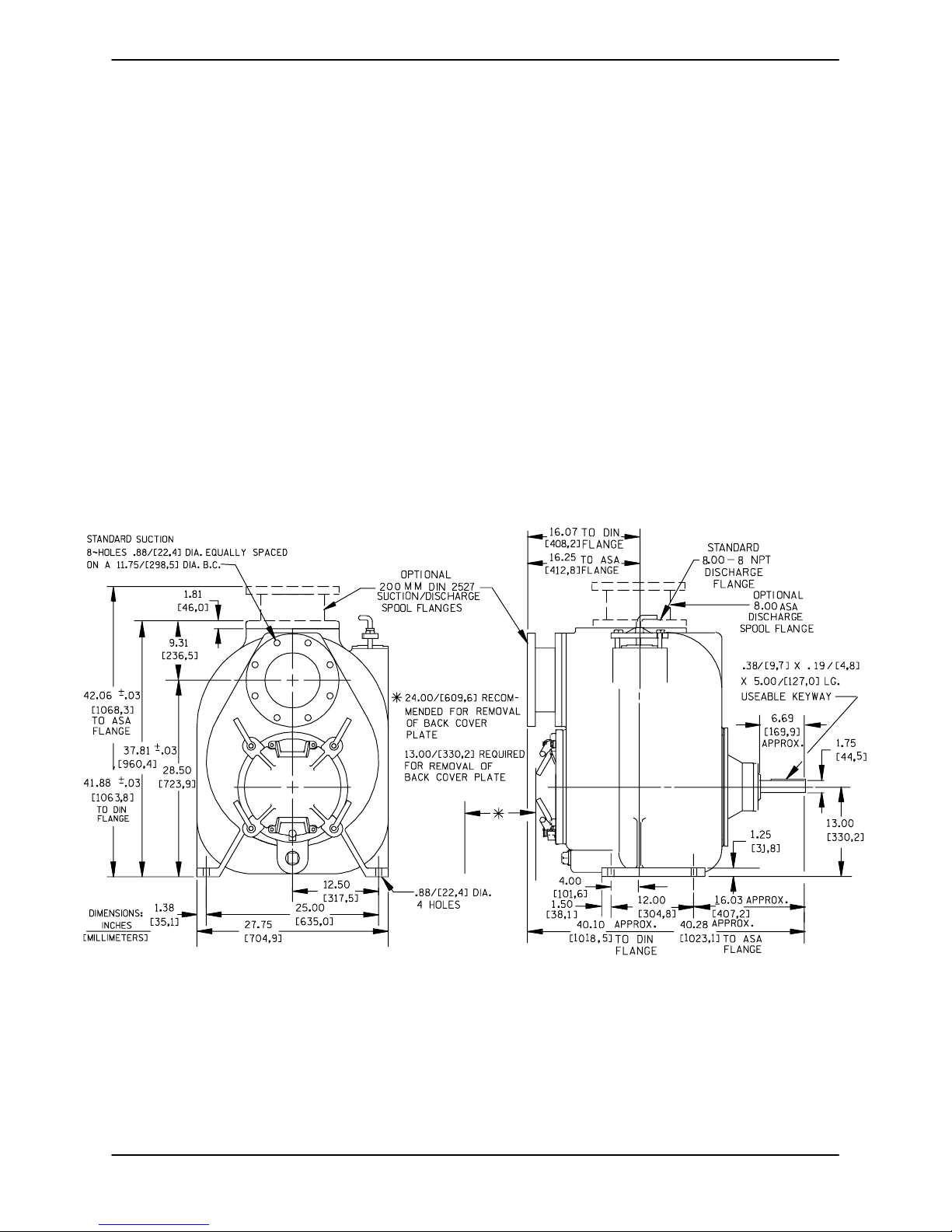
SeeFigure1fortheapproximatephysicaldimensionsofthispump.
NOTE: OPTIONAL ASA OR DIN STANDARD SUCTION & DISCHARGE SPOOL FLANGES AVAILABLE
Figure 1. Pump Model T8A60-B
PAGE B -- 1INSTALLATION
Page 7
OM--01930--03 TSERIES
PREINSTALLATION INSPECTION
Thepump assembly wasinspected and tested beforeshipment fromthe factory. Beforeinstallation,
inspect the pump fordamage which may have occurred during shipment. Check as follows:
a. Inspect the pump forcracks,dents, damaged
threads, and other obvious damage.
b. Check for and tighten loose attaching hard-
ware. Since gaskets tend to shrink after drying, check for loose hardware at mating surfaces.
c. Carefullyread all warnings and cautions con-
tained in this manual or affixed to the pump,
and perform all duties indicated. Note the direction of rotation indicated on the pump.
Check that the pump shaft rotates counterclockwise when facing the impeller.
POSITIONING PUMP
Lifting
Use lifting equipment with a capacity of at least
6,000pounds (2721,6kg). Thispump weighs a pproximately1,200 pounds (544,3 kg),notincludingthe weight of accessories and base. Customer
installed equipment such as suction and dischargepipingmustberemoved beforeattempting
to lift.
Thepumpassemblycanbeseriously
damagedif thecablesor chainsused tolift
andmovetheunitareimproperlywrapped
around the pump.
Only operate this pump in the direction indicated by the arrow on the pump body
and on the accompanying decal. Refer to
ROTATION in OPERATION,SectionC.
d. Check levels and lubricate as necessary. Re-
fer to LUBRICATION in the MAINTENANCE
AND REPAIR section of this manual and perform duties as instructed.
e.Ifthepumpandpowersourcehavebeen
stored for more than 12 months, some of the
components or lubricants may have exceeded their maximum shelf life. These must
be inspected or replaced to ensure maximum pump service.
Mounting
Locatethepumpinanaccessibleplaceascloseas
practicalto the liquid being pumped. Levelmounting is essential for proper operation.
The pump may have to be supported or shimmed
to provide for level operation or to eliminate vibration.
Clearance
When positioning the pump, allow a minimum
clearance of 24 inches (609,6 mm) in front of the
back coverto permit removal of the coverand easy
access to the pump interior.
SUCTION AND DISCHARGE PIPING
If the maximum shelf life has been exceeded, or if
anything appears to be abnormal, contact your
Gorman-Rupp distributor or the factory to determinethe repairor updating policy. Donotputthe
pump into service until appropriate action has
been taken.
PAGE B -- 2 INSTALLATION
Pump performance is adversely effected by increased suction lift, discharge elevation, and friction losses. See the performance curve and operating range shown on Page E-1 to be sure your
overall application allows pump to operate within
thesafeoperationrange.
Page 8

OM--01930--03TSERIES
Materials
Either pipe or hose maybe used for suction and
discharge lines; however, the materials must be
compatiblewith theliquidbeingpumped.If hoseis
used insuction lines, it mustbe the rigid-wall, reinforcedtype toprevent collapseunder suction.Using piping couplings in suction lines is not recommended.
Line Configuration
Keep suction and discharge lines as straight as
possible to minimize friction losses. Make minimum use of elbows and fittings, which substantiallyincreasefriction loss.Ifelbowsarenecessary,
use the long-radius type to minimize friction loss.
Connections to Pump
Before tightening a connecting flange, align it exactlywith the pump port. Never pulla pipe line into
place by tightening the flange bolts and/or couplings.
Lines near the pump must be independently supported to avoid strain on the pump which could
cause excessive vibration, decreased bearing life,
and increased shaft and seal wear. If hose-type
linesareused, theyshouldhaveadequatesupport
to secure them when filled with liquid and under
pressure.
line must always slope upward to the pump from
the source of the liquid being pumped; if the line
slopes down to the pump at any point along the
suction run, air pockets will be created.
Fittings
Suction lines shouldbe the same size as the pump
inlet. If reducers are used in suction lines, they
should be the eccentric type, and should be installedwith the flat part ofthe reducers uppermost
to avoid creating air pockets. Valves are not normally used in suction lines, but if a valve is used,
install it with the stem horizontal to avoid air pockets.
Strainers
If a strainer is furnished with the pump, be certain
touseit; any sphericalsolidswhichpass througha
strainer furnished with the pump will also pass
through the pump itself.
If a strainer is not furnished with the pump, but is
installed by the pump user, make certain that the
total area of the openings in the strainer is at least
three or four times the cross section of the suction
line,and that the openings will not permit passage
of solids larger than the solids handling capability
of the pump.
Thispumpisdesignedtohandleupto3inch(76,2)
diameter spherical solids.
Gauges
Most pumps are drilled and tapped for installing
discharge pressure and vacuum suction gauges.
If these gauges are desired for pumps that are not
tapped, drill and tap the suction and discharge
lines not less than 18 inches (457,2 mm) from the
suction and discharge ports and install the lines.
Installationcloserto the pump may result in erratic
readings.
SUCTION LINES
To avoid airpockets whichcouldaffect pumppriming, the suction line must be as short and direct as
possible.When operationinvolvesasuctionlift,the
Sealing
Since even a slight leak will affect priming, head,
and capacity, especially when operating with a
highsuction lift, all connectionsin the suction line
should be sealed with pipe dope to ensure an airtight seal. Follow the sealant manufacturer’s recommendations when selecting and applying the
pipe dope. The pipe dope should be compatible
with the liquid being pumped.
Suction Lines In Sumps
If a single suction line is installed in a sump, it
should be positioned away from the wall of the
sumpat a distanceequal to 1 1/2 times the diameter of the suction line.
PAGE B -- 3INSTALLATION
Page 9
OM--01930--03 TSERIES
If there is a liquid flow from an open pipe into the
sump, the flow should be kept away from the suctioninlet because the inflowwill carry air down into
the sump, and air entering the suction line will reduce pump efficiency.
Ifit is necessary to position inflowclose to the suctioninlet,installa bafflebetween theinflowand the
suction inlet at a distance 1 1/2 times the diameter
of the suction pipe. The baffle will allow entrained
air to escape from the liquid before it is drawn into
the suction inlet.
If two suction lines are installed in a single sump,
theflowpaths mayinteract, reducing theefficiency
of one or both pumps. T o avoid this, position the
suction inlets s o that they are separated by a dis-
tance equal to at least 3 times the diameter of the
suction pipe.
Suction Line Positioning
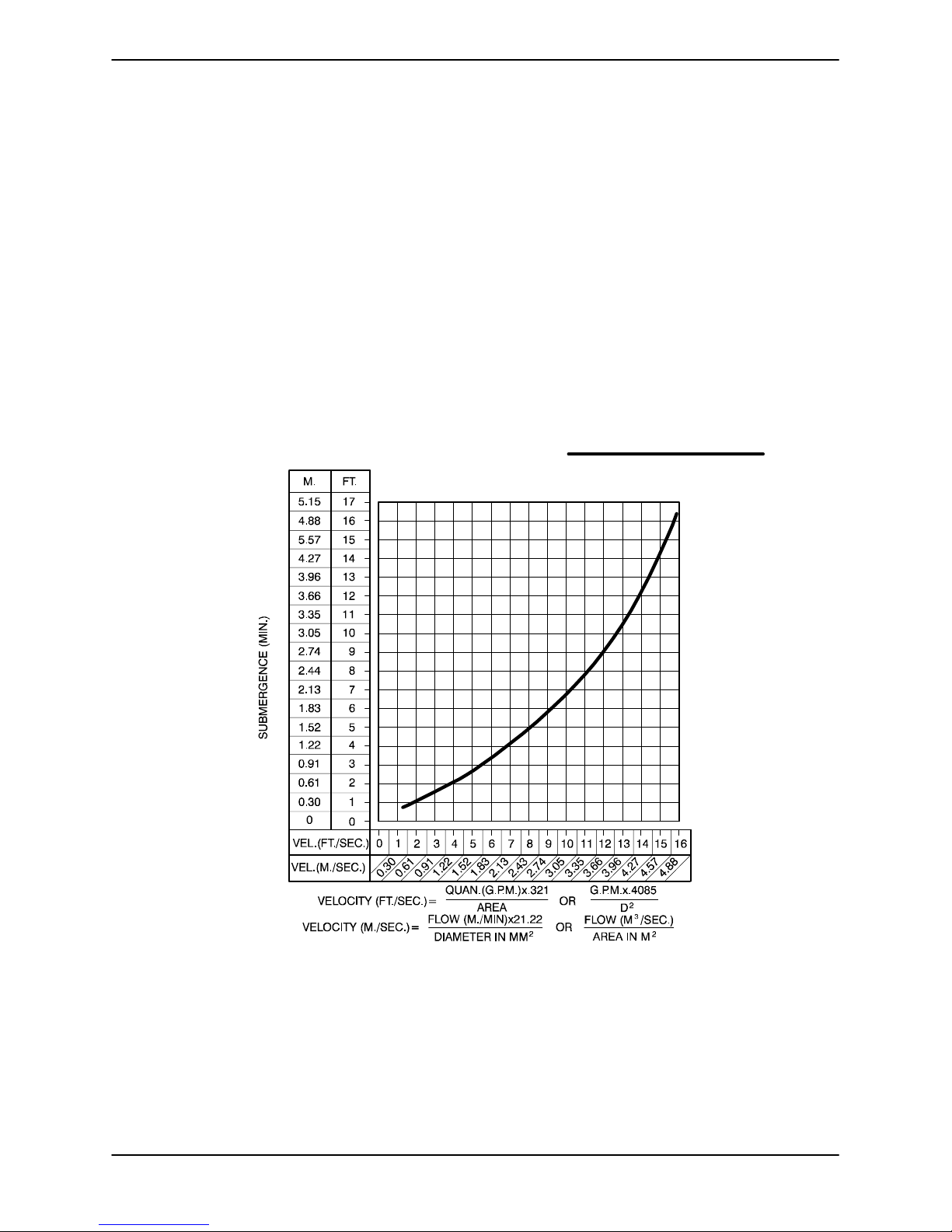
The depth of submergence of the suction line is
critical to efficient pump operation. Figure 2 shows
recommended minimum submergence vs. veloc-
ity.
NOTE
The pipe submergence required may be reduced
byinstallinga standard pipe increaserfitting atthe
endof thesuction line. The largeropening size will
reduce the inlet velocity. Calculate the required
submergence using the following formula based
on the increased opening size (area or diameter).
Figure 2. Recommended Minimum Suction Line Submergence vs. Velocity
DISCHARGE LINES
Siphoning
Donot terminate the discharge lineat a level lower
than that of the liquid being pumped unless a siphon breaker is used in the line. Otherwise, a si-
PAGE B -- 4 INSTALLATION
phoning action causing damage to the pump
could result.
Valves
If a throttling valve is desired in the discharge line,
useavalveaslargeasthelargestpipetominimize
Page 10
friction losses. Never install a throttling valve in a
suction line.
OM--01930--03TSERIES
Withhighdischargeheads,itisrecommendedthat
a throttling valve and a system check valve be installed in the discharge line to protect the pump
from excessive shock pressure and reverse rotation when it is stopped.
If the application involves a highdischarge
head, gradually close the discharge
throttling valve before stopping the pump.
Bypass Lines
Self-primingpumps are not air compressors. Dur ingtheprimingcycle, air from the suction line must
be vented to atmosphere on the discharge side. If
the discharge line is open, this air will be vented
through the discharge. However, if a check valve
has been installed in the discharge line, the dischargesideofthepumpmustbeopenedtoatmosphericpressurethrough abypass line installedbetween the pump discharge and the check valve. A
self-priming centrifugal pump will not prime if
there is sufficientstatic liquidhead to hold the discharge check valve closed.
Abypasslinethatisreturnedtoawetwell
must be securedagainstbeing drawninto
the pump suction inlet.
It is also recommended that pipe unions be installed at each 90_ elbow in a bypass line to ease
disassembly and maintenance.
In high discharge head applications (more than
30 feet), an excessive amount of liquid may be bypassed and forced back to the wet well under the
full working pressure of the pump; this will reduce
overallpumpingefficiency.Therefore, itisrecom-
mended thata Gorman-RuppAutomatic AirRelease Valve be installed in the bypass line.
Gorman-Rupp Automatic Air Release Valves are
reliable, and require minimum maintenance. See
AUTOMATICAIR RELEASEVALVE in thissection
for installation and theory of operation of the Automatic Air Release Valve. Consult your GormanRupp distributor, or contact the Gorman-Rupp
CompanyforselectionofanAutomaticAirRelease
Valve to fit your application.
If theinstallation involves a flooded suction suchas
abelow-groundliftstation.Apipeunionand manualshut-off valve may beinstalledin the bleed lineto
allowserviceofthevalvewithoutshuttingdownthe
station, and to eliminate the possibilityof flooding.
If a manual shut-off valve is installed anywhere in
the airrelease piping, it must be afull-openingball
type valve to prevent plugging by solids.
NOTE
Thebypass line should be sized so that it does not
affect pump discharge capacity; however, the bypass line should be at least 1 inch in diameter to
minimize the chance of plugging.
Inlow dischargeheadapplications(lessthan 30
feet), itisrecommendedthatthebypassline be run
back to the wet well, and located 6 inches below
the water level or cut -off point of the low level
pump. In some installations, this bypass line may
beterminatedwith asix-to-eightfootlengthof11/4
inch I.D. smooth-bore hose; air and liquid vented
during the priming process will then agitate the
hose and break up any solids, grease, or other
substances likely to cause clogging.
If a manual shut-off valve is installed in
a bypass line, it must not be left closed
duringoperation
.Aclosedmanualshutoff valve may cause a pump which has
lost prime to continue to operate without reaching prime, causing dangerous
overheating and possible explosive
rupture of the pump casing. P
ersonnel
could be severely injured.
Allow an over-heated pump to cool before servicing. Do not remove plates,
PAGE B -- 5INSTALLATION
Page 11
OM--01930--03 TSERIES
covers,gauges,orfittingsfroman overheated pump. Liquid within the pump
canreach boiling temperatures,and vaporpressure within thepumpcancause
parts being disengaged to be ejected
with great force. After the pump cools,
drain the liquid from the pump by removing the casing drain plug. Use caution when removing the plug to prevent
injury to personnel from hot liquid.
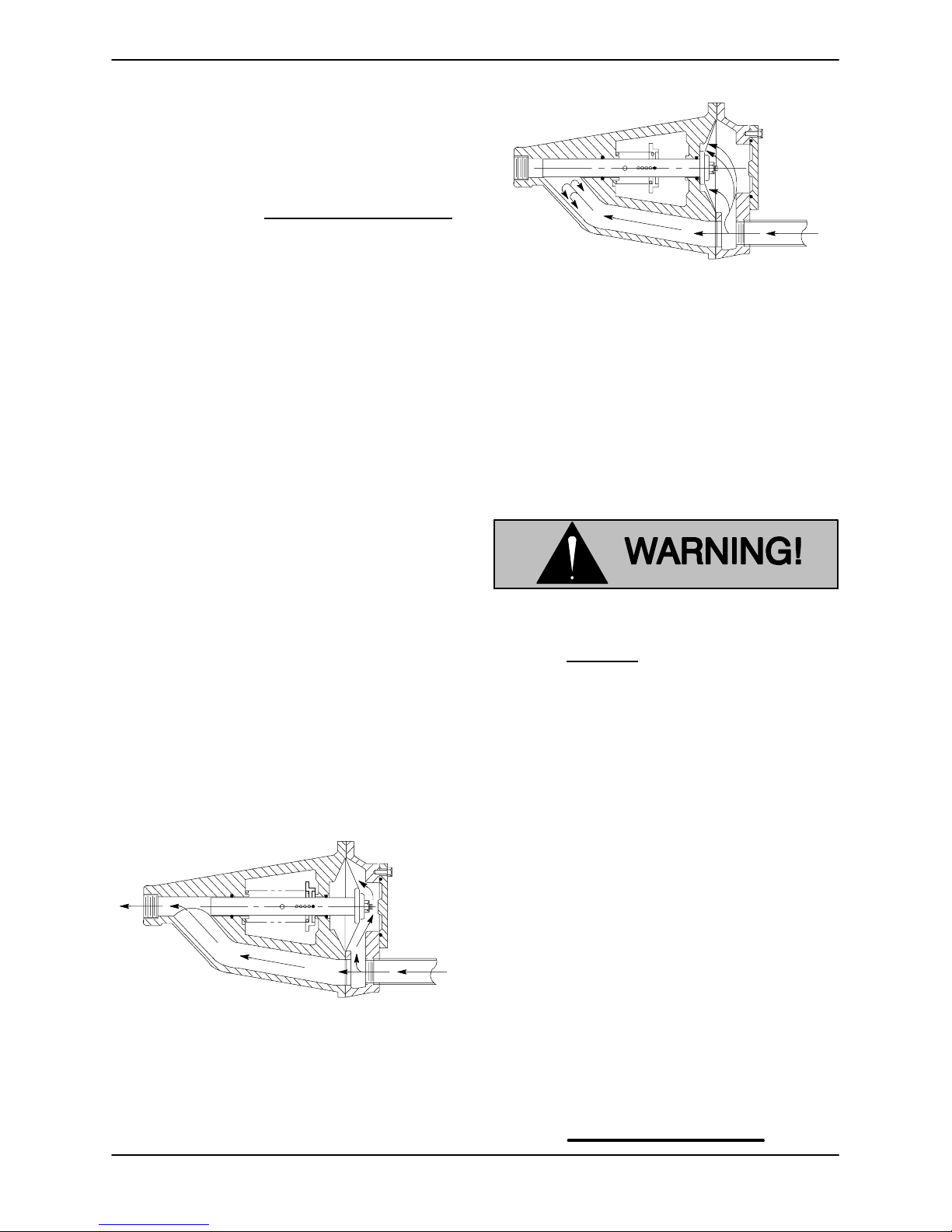
AUTOMATIC AIR RELEASE VALVE
When properly installed and correctly adjusted to
the specific hydraulic operating conditions of the
application, the Gorman-Rupp Automatic Air ReleaseValvewillpermitairtoescapethroughthebypass line, and then close automatically when the
pump is fully primed and pumping at full capacity.
When the pump is fullyprimed, pressure resulting
from flow against the valve diaphragm compresses the spring and closesthe valve(Figure 4).
The valve will remain closed, reducing the bypass
ofliquidto1 to 5gallonsper minute, untilthepump
loses its prime or stops.
Figure 4. Valve in Closed Position
Theory of Operation
Figures 3 and 4 show a cross-sectional view of the
AutomaticAir Release Valve, and a corresponding
description of operation.
Figure3.ValveinOpenPosition
Duringthepriming cycle, airfromthe pump casing
flowsthroughthebypassline,andpassesthrough
theAirReleaseValvetothewetwell(Figure3).
Some leakage (1 to 5 gallons per minute) will occur when the valve is fully
closed. Be sure thebypasslineisdirected back to the wet well or tank to
prevent hazardous spills.
Whenthe pump shutsdown, the springreturnsthe
diaphragm t o its original position. Any solids that
mayhaveaccumulated inthe diaphragmchamber
settle to the bottomand are flushedout during the
next priming cycle.
NOTE
The valve will remain open if the pump does not
reach its designed capacity or head. Valve closing
pressureis dependentupon thedischargeheadof
the pump at full capacity. The range of the valve
closing pressure is established by the tensionrate
ofthespring asordered fromthefactory.Valveclosing pressure can be further adjusted to the exact
system requirements by moving the spring retaining pin up or down the plunger rod to increase or
decrease tension on the spring. Contact your Gorman-Rupp distributor or the Gorman-Rupp Company for information about an Automatic Air Release Valve for your specific application.
PAGE B -- 6 INSTALLATION
Page 12
OM--01930--03TSERIES
Air Release Valve Installation
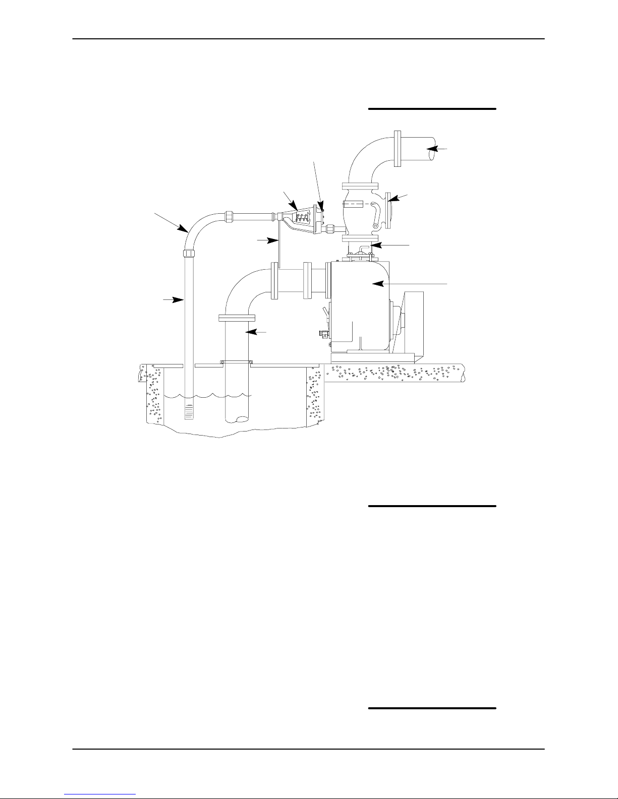
The Automatic Air Release Valve must be independently mounted in a horizontal position and
connected to the discharge line of th e self-priming
centrifugal pump (see Figure 5).
CLEAN-OUT
COVER
INSTALL AIR RELEASE VALVE
IN HORIZONTAL POSITION
90_ LONG
RADIUS
ELBOW
SUPPORT
BRACKET
BLEED LINE 1”
(25,4 MM) DIA. MIN.
(CUSTOMER
FURNISHED)
EXTEND 6”
(152,4 MM)
BELOW LIQUID
LEVEL SURFACE
SUCTION
LINE
NOTE
IftheAirReleaseValveistobeinstalledonastaged
pump application, contact the factory for specific
installationinstructions.
DISCHARGE PIPE
DISCHARGE
CHECK VALVE
PUMP DISCHARGE
SELF-PRIMING
CENTRIFUGAL
PUMP
WET WELL
OR SUMP
Figure 5. Typical Automatic Air Release Valve Installation
The valve inlet line must be installed between the
pumpdischargeportandthenon-pressurizedside
of the discharge check valve. The valve inlet is at
thelargeendofthevalvebody,andisprovided
with standard 1 inch NPT pipe threads.
The valve outlet is located at the opposite end of
the valve, and is also equipped with standard 1
inch NPT pipe threads. The outlet should be connectedtoa bleedlinewhich slopes backto thewet
well or sump.Thebleed line must be the same size
asthe inlet piping,orlarger. Ifpipingisused for the
bleed line, avoid the use of elbows whenever possible.
NOTE
It is recommended that each Air Release Valve be
fitted with an independent bleeder line directed
back to the wet well. However, if multiple Air Release Valves are installed in a system, the bleeder
lines may be directedto a common manifold pipe.
Contact your Gorman-Rupp distributor or the Gor-
man-RuppCompany for information aboutinstallation of an Automatic Air Release Valve for your specific application.
ALIGNMENT
Thealignment ofthe pumpand itspower sourceis
critical for trouble-free mechanical operation. In
either a flexible coupling or V-belt driven system,
thedriver and pumpmust bemounted sothat t h eir
shaftsare alignedwith and paralleltoeach other.It
is imperative that alignment be checked after the
pump and piping are installed, and before operation.
NOTE
Check Rota tion, Section C, before final alignment
of the pump.
Whenmountedat the Gorman-Ruppfactory, driver
andpumparealignedbeforeshipment.Misalign-
PAGE B -- 7INSTALLATION
Page 13
OM--01930--03 TSERIES
ARA
A
V
ment will occur in transit and handling. Pumps
must be checked and realigned before operation.
Beforechecking alignment,tighten the foundation
bolts. The pump casing feet and/or pedestal feet,
andthedrivermountingboltsshouldalsobetightly
secured.
When checking alig nment, disconnect
the power source to ensure that the
pump will remain inoperative.
Adjusting the alignment in one direction
may alter the alignment in another direction. check each procedure after altering
alignment.
Coupled Drives
When using couplings, the axis of the power
source must be aligned to the axis of the pump
shaft in both the horizontal and vertical planes.
Mostcouplingsrequire a specific gap or clearance
between the driving and the driven shafts. Refer to
the coupling manufacturer’s service literature.
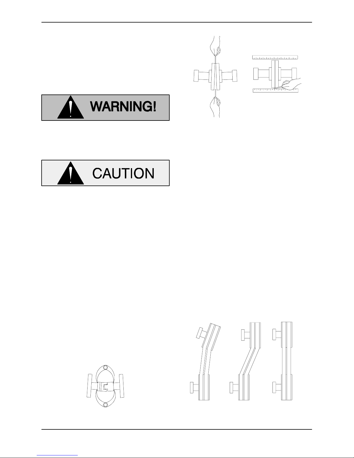
Alignspider inserttypecouplingsbyusingcalipers
to measure the dimensions on the circumference
of the outer ends of the coupling hub every 90 degrees. The coupling is in alignment when the hub
ends are the same distanceapart at all points(see
Figure 6).
Figure 7. Aligning Non-Spider Type Couplings
Align non-spider type couplings by using a feeler
gaugeortapergaugebetweenthecouplinghalves
every 90 degrees. The coupling is in alignment
whenthehubsarethesamedistanceapartatall
points (see Figure 7).
Checkparalleladjustment bylayingastraightedge
across both coupling rims at the top, bottom, and
side. When the straightedge rests evenly on both
halves of the coupling, the coupling is in horizontal
parallel alignment. If the coupling is misaligned,
use a feeler gauge between the coupling and the
straightedge to measure the amount of misalignment.
V-Belt Drives
When using V-belt drives, the power source and
the pump must be parallel. Use a straightedge
alongthe sides ofthe pulleystoensurethatthepulleys are properly aligned (see Figure 8). In drive
systemsusingtwo ormore belts, make certainthat
the belts are a matched set; unmatched sets will
cause accelerated belt wear.
Figure 6. Aligning Spider-Type Couplings
PAGE B -- 8 INSTALLATION
MISALIGNED:
SHAFTS
NOT P
LLEL
MISALIGNED:
SHAFTS
NOT IN LINE
ALIGNED:SHAFTS
PARALLEL AND
SHE
ES IN LINE
Figure 8. Alignment of V-Belt Driven Pumps
Page 14
Tightenthe belts inaccordancewiththe beltmanufacturer’s instructions. If the belts are too loose,
they will slip; if the belts are too tight, there will be
excessivepower lossand possiblebearing failure.
Select pulleys that will match the proper speed ratio; overspeeding the pump may damage both
pump and power source.
OM--01930--03TSERIES
Do not operate the p ump without the
guards in place over the rotating parts.
Exposed rotating parts can catch clothing, fingers,or tools,causing severe injury to personnel.
PAGE B -- 9INSTALLATION
Page 15
T-SERIES
OM--01930--03
OPERATION --- SECTION C
Review all SAFETY information in Section A.
Follow the instructions on all tags, labels and decals attached to the pump.
This pump is designed to handle mild
corrosives, and industrial slurries containinglargeentrainedsolids.Donotattempt to pump volatile, flammable or
corrosive liquids which may damage
the pump or endanger personnel as a
result of pump failure.
Pump speed and operating conditions
must be within the performance range
shownonpageE-1.
Add liquid to the pump casing when:
1. The pump is being put into service for the
first time.
2. The pumphas notbeenused for aconsiderable length of time.
3. The liquid in the pump casing has evaporated.
Once the pump casing has been filled, the pump
will prime and reprime as necessary.
After filling the pump casing, reinstall
and tighten the fill plug. Do not attempt
to operate the pump unlessall connect ing piping is securely installed. Otherwise, liquid in the pump forced out
under pressure could cause injury to
personnel.
To fill the pump, remove the pump casing fillcover
or fill plug in the top of the casing, and add clean
liquid until the casing is filled. Replace the fill cover
or fill plug before operating the pump.
PRIMING
Install the pump and piping as described in INSTALLATION. Make sure that the piping connec-
tions are tight, and that the pump is securely
mounted. Check that the pump is properly lubricated (see LUBRICATION in MAINTENANCE
AND REPAIR).
This pump is self-priming, but the pump should
never be operated unless there is liquid in the
pump casing.
Never operate this pump unless there is
liquid in the pump casing. The pump will
not prime when dry.extended operationof
a dry pump will destroy the seal assembly.
OPERATION PAGE C -- 1
STARTING
Consult the operations manual furnished with the
power source.
Rotation
The correct direction of pump rotation is counterclockwise when facing the impeller. The pump
couldbe damaged and performance adversely a ffected by incorrect rotation. If pump performance
is not within the specified limits (see the curve on
page E-1), check the direction of power source rotation before further troubleshooting.
If an electric motor is used to drive the pump, remove V-belts, couplings, or otherwise disconnect
the pump from the motor before checking motor
rotation. Operate the motor independently while
observingthe direction of the motor shaft, or cooling fan.
Page 16
T-SERIESOM--01930--03
Ifrotationisincorrecton a three-phasemotor,have
a qualified electrician interchange any two of the
three phase wires to change direction.If rotationis
incorrect on asingle-phase motor,consult theliterature supplied with the motor for specific instructions.
OPERATION
Lines With a Bypass
Ifa Gorman-Rupp Automatic Air ReleaseValvehas
been installed, the valve will automatically open to
allow the pump to prime, and automatically close
after priming is complete (see INSTALLATION for
Air Release Valve operation).
If the bypass line is open, air from the suction line
willbe dischargedthrough the bypass line back to
the wet well during the priming cycle. Liquid will
then continue to circulate through the bypass line
while the pump is in operation.
pressure,and causethe pump casing to
rupture or explode.
Leakage
No leakage should be visible at pump mating surfaces, or at pump connections or fittings. Keep all
lineconnectionsandfittingstight to maintainmaximum pump efficiency.
Liquid Temperature And Overheating
The maximum liquid temperature for this pump is
160_ F(71_ C). Donot apply it at ahigheroperat-
ing temperature.
Overheating can occur if operated with the valves
in the suction or discharge lines closed. Operating
against closed valves could bring the liquid to a
boil, build pressure, and cause the pump to rupture or explode. If overheating occurs, stop the
pump and allow it to cool before servicing it. Refill
the pump casing with cool liquid.
Lines Without a Bypass
Open all valves in t he discharge line and start the
power source. Priming is indicated by a positive
reading on the discharge pressure gauge or by a
quieteroperation. Thepump maynot primeimmediately because the suction line must first fill with
liquid. If thepumpfails to primewithinfive minutes,
stop it and check the suction line for leaks.
Afterthepumphas been primed,partiallyclosethe
discharge line throttling valve in order to fill the line
slowly and guard against excessive shock pressure which could damage pipe ends, gaskets,
sprinkler heads, and any other fixtures connected
to the line. When the discharge line is completely
filled,adjustthethrottlingvalve to the required flow
rate.
Do not operate the pump against a
closed discharge throttling valve for
longperiodsof time.If operatedagainst
a closed discharge throttling valve,
pump components will deteriorate, and
the liquid could come to a boil, build
Allow an over-heated pump to cool before servicing. Do not remove plates,
covers,gauges,orfittingsfroman overheated pump. Liquid within the pump
canreach boiling temperatures,and vaporpressure within thepumpcancause
parts being disengaged to be ejected
with great force. After the pump cools
drain the liquid from the pump by removing the casing drain plug. Use caution when removing the plug to prevent
injury to personnel from hot liquid.
Asa s afeguard against ruptureor explosiondueto
heat, this pump is equipped with a pressure relief
valve which will open if vapor pressure within the
pumpcasingreachesacriticalpoint. Ifoverheating
does occur, stop the pump immediately and allow
it to cool before servicing it. Approach any over-
heated pump cautiously. It is recommended that
the pressure relief valve assembly be replaced at
each overhaul, or any time the pump casing overheats and activates the valve. Never replace this
valve with a substitute w hich has not been specified or provided by the Gorman-Rupp Company.
,
OPERATIONPAGE C -- 2
Page 17
T-SERIES
OM--01930--03
Strainer Check
If a suction strainer has been shipped with the
pump or installed by the user, check the strainer
regularly, and clean it as necessary. The strainer
shouldalsobechecked ifpumpflowrate beginsto
drop. If a vacuum suction gauge has been installed, monitor and record the readings regularly
to detect strainer blockage.
Never introduce air or steam pressure into the
pump casing or pipingto remove a blockage. This
could result in personal injury or damage to the
equipment. If backflushing is absolutely necessary, liquidpressure must be limited to 50% of the
maximum permissible operating pressure shown
on the pump performance curve.
Pump Vacuum Check
Withthe pumpinoperative,installavacuumgauge
in the system, using pipe dope on the threads.
Block the suction line and start the pump. At oper-
ating speed the pump should pull a vacuum of 20
inches (508,0 mm) or more of mercury. If it does
not, check for air leaks in the seal, gasket, or discharge valve.
head, gradually close the discharge
throttling valve before stopping the pump.
After stopping the pump, disconnect or lock out
the power source to ensure that the pump willre-
main inoperative.
Cold Weather Preservation
In below freezing conditions, drain the pump to
preventdamage from freezing.Also, clean outany
solids by flushing with a hose. Operate the pump
for approximatelyone minute; this will remove any
remaining liquid that could freeze the pump rotating parts. If the pump will be idle for more than a
few hours, or if it has been pumping liquids containing a large amount of solids, drain the pump,
and flush it thoroughly with cleanwater.To prevent
large solids from clogging the drain port and preventing the pump from completely draining, insert
a rod or stiff wire in the drain port, and agitate the
liquid during the draining process. Clean out any
remaining solids by flushing with a hose.
BEARING TEMPERATURE CHECK
Openthesuction line, andread the vacuumgauge
with the pump primed and at operation speed.
Shut off the pump. Thevacuum gauge reading will
immediately drop proportionate to static suction
lift,andshould thenstabilize. Ifthevacuumreading
falls off rapidly after stabilization, an air leak exists.
Before checking for the source of the leak, check
the point of installation of the vacuum gauge.
STOPPING
Never halt the flow of liquid suddenly. If the liquid
being pumped is stopped abruptly, damaging
shock waves can be transmitted to the pump and
piping system. Close all connecting valves slowly.
On engine driven pumps, reduce the throttle
speed slowlyand allowtheengine toidle brieflybefore stopping.
If the application involves a highdischarge
Bearingsnormally run at higher than ambient temperatures because of heat generated by friction.
Temperatures up to 160_F(71_ C) are considered
normalforbearings,andthey canoperatesafelyto
at least 180_F(82_ C).
Checkingbearingtemperaturesbyhand is inaccurate. Bearing temperatures can be measured accurately by placing a contact-type thermometer
against the housing. Record this temperature for
future reference.
A sudden increase in bearing temperature is a
warning that the bearings are at the point of failing
to operate properly. Make certain that the bearing
lubricant is of the proper viscosity and at the correct level (see LUBRICATION in MAINTENANCE
AND REPAIR). Bearing overheating can also be
caused by shaft misalignmentand/or excessive vibration.
When pumps are first started, the bearings may
seem to run at temperatures above normal. Continued operation should bring the temperatures
down to normal levels.
OPERATION PAGE C -- 3
Page 18
TSERIES OM--01930--03
TROUBLESHOOTING --- SECTION D
Review all SAFETY information in Section A.
Before attempting to open
or service the pump:
1. Familiarize yourself with this manual.
2. Disconnect or lock out the power source to
ensure that the pump will remain i noperative.
3. Allow the pump to cool if overheated.
4. Check the temperature before opening any
covers, plates, or plugs.
5. Close the suction and discharge valves.
6. Vent the pump slowly and cautiously.
7. Drain the pump.
TROUBLE POSSIBLE CAUSE PROBABLE REMEDY
PUMP FAILS TO
PRIME
PUMP STOPS OR
FAILS TO DELIVER
RATED FLOW OR
PRESSURE
Not enough liquid in casing. Add liquid to casing. See PRIM-
ING.
Suction check valve contaminated or
damaged.
Air leak in suction line.
Lining of suction hose collapsed.
Leaking or worn seal or pump gasket. Check pump vacuum. Replace
Suction lift or discharge head too high. Check piping installation and in-
Strainer clogged. Check strainer and clean if neces-
Air leak in suction line.
Lining of suction hose collapsed.
Leaking or worn seal or pump gasket. Check pump vacuum. Replace
Clean or replace check valve.
Correct leak.
Replace suction hose.
leakingorwornsealorgasket.
stall bypass line if needed. See
INSTALLATION.
sary.
Correct leak.
Replace suction hose.
leakingorwornsealorgasket.
Strainer clogged. Check strainer and clean if neces-
Suction intake not submerged at
proper level or sump too small.
TROUBLESHOOTING PAGE D -- 1
sary.
Check installationand correctsub-
mergence as needed.
Page 19

OM--01930--03
TROUBLE POSSIBLE CAUSE PROBABLE REMEDY
TSERIES
PUMP STOPS OR
FAILS TO DELIVER
RATED FLOW OR
PRESSURE (cont.)
PUMP REQUIRES
TOO MUCH
POWER
Impellerorotherwearingpartsworn
or damaged.
Replace worn or damaged parts.
Check that impeller is properly
centered and rotates freely.
Impeller clogged. Free impeller of debris.
Pump speed too slow. Check driver output; check belts
or couplings for slippage.
Discharge head too high. Install bypass line.
Suction lift t oo high. Measureliftw/vacuumgauge.Re-
duce lift and/or friction losses in
suction line.
Pump speed too high. Check driver output; check that
sheaves or couplings are cor-
rectly sized.
Discharge head too low. Adjust discharge valve.
Liquid solution too thick. Dilute if possible.
Bearing(s) frozen. Disassemble pump and check
bearing(s).
PUMP
Liquid solution too thick. Dilute if possible.
CLOGS FREQUENTLY
Discharge flow too slow. Open discharge valve fully to in-
Suction check valve or foot valve
clogged or binding.
EXCESSIVE NOISE Cavitation in pump.
Pumping entrained air.
Pump or drive not securelymounted.
Impeller clogged or damaged.
crease flow rate, and run power
source at maximum governed
speed.
Clean valve.
Reduce suction lift and/or friction
losses in suction line. Record vac-
uumand pressure gaugereadings
and consult local representative or
factory.
Locateand eliminatesourceof air
bubble.
Secure mounting hardware.
Clean out debris; replace dam-
aged parts.
TROUBLESHOOTINGPAGE D -- 2
Page 20
TSERIES OM--01930--03
TROUBLE POSSIBLE CAUSE PROBABLE REMEDY
BEARINGS
RUN TOO HOT
Bearing temperature is high, but
within limits.
Low or incorrect lubricant. Check for proper type and level of
Suction and discharge lines not
properly supported.
Drive misaligned. Align drive properly.
PREVENTIVE MAINTENANCE
Sincepumpapplicationsareseldomidentical,and
pump wear is directly affected by such things as
the abrasive qualities, pressure and temperature
oftheliquidbeingpumped, thissectionisintended
only to provide general recommendations and
practices for preventive maintenance. Regardless
of the application however,following a routine preventive maintenance schedule will help assure
trouble-free performance and long life from your
Gorman-Rupp pump. For specific questions concerning your application, contact your GormanRupp distributor or the Gorman-Rupp Company.
Record keeping is an essential component of a
good preventive maintenance program. Changes
in suction and discharge gauge readings (if so
Check bearing temperature regu-
larly to monitor any increase.
lubricant.
Check piping installation for
proper support.
equipped) between regularly scheduled inspections can indicate problems that can be corrected
before system damage or catastrophic failure occurs.The appearance of wearingpartsshouldalso
bedocumentedat eachinspectionfor comparison
as well. Also, if records indicate that a certain part
(such as the seal) fails at approximately the same
duty cycle, the part can be checked and replaced
beforefailureoccurs, reducing unscheduleddown
time.
For new applications, a first inspection of wearing
partsat250hourswillgiveinsightintothewearrate
foryourparticularapplication.Subsequentinspections should be performed at the intervals shown
on the chart below. Critical applications should be
inspected more frequently.
TROUBLESHOOTING PAGE D -- 3
Page 21
OM--01930--03
TSERIES
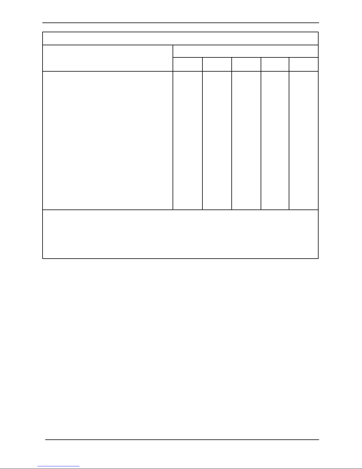
Preventive Maintenance Schedule
Service Interval*
Item
General Condition (Temperature, Unusual
Noises or Vibrations, Cracks, Leaks,
Loose Hardware, Etc.) I
Pump Performance (Gauges, Speed, Flow) I
Bearing Lubrication I R
Seal Lubrication (And Packing Adjustment,
If So Equipped) I R
V-Belts (If So Equipped) I
Air Release Valve Plunger Rod (If So Equipped) I C
Front Impeller Clearance (Wear Plate) I
Rear Impeller Clearance (Seal Plate) I
Check Valve I
Pressure Relief Valve (If So Equipped) C
Pump and Driver Alignment I
Shaft Deflection I
Bearings I
Bearing Housing I
Piping I
Driver Lubrication --- See Mfgr’s Literature
Daily Weekly Monthly Semi-
Annually
Annually
Legend:
I = Inspect, Clean, Adjust, Repair or Replace as Necessary
C= Clean
R= Replace
* Service interval based on an intermittent duty cycle equal to approximately 4000 hours annually.
Adjust schedule as required for lower or higher duty cycles or extreme operating conditions.
TROUBLESHOOTINGPAGE D -- 4
Page 22
TSERIES
OM--01930--03
PUMP MAINTENANCE AND REPAIR --- SECTION E
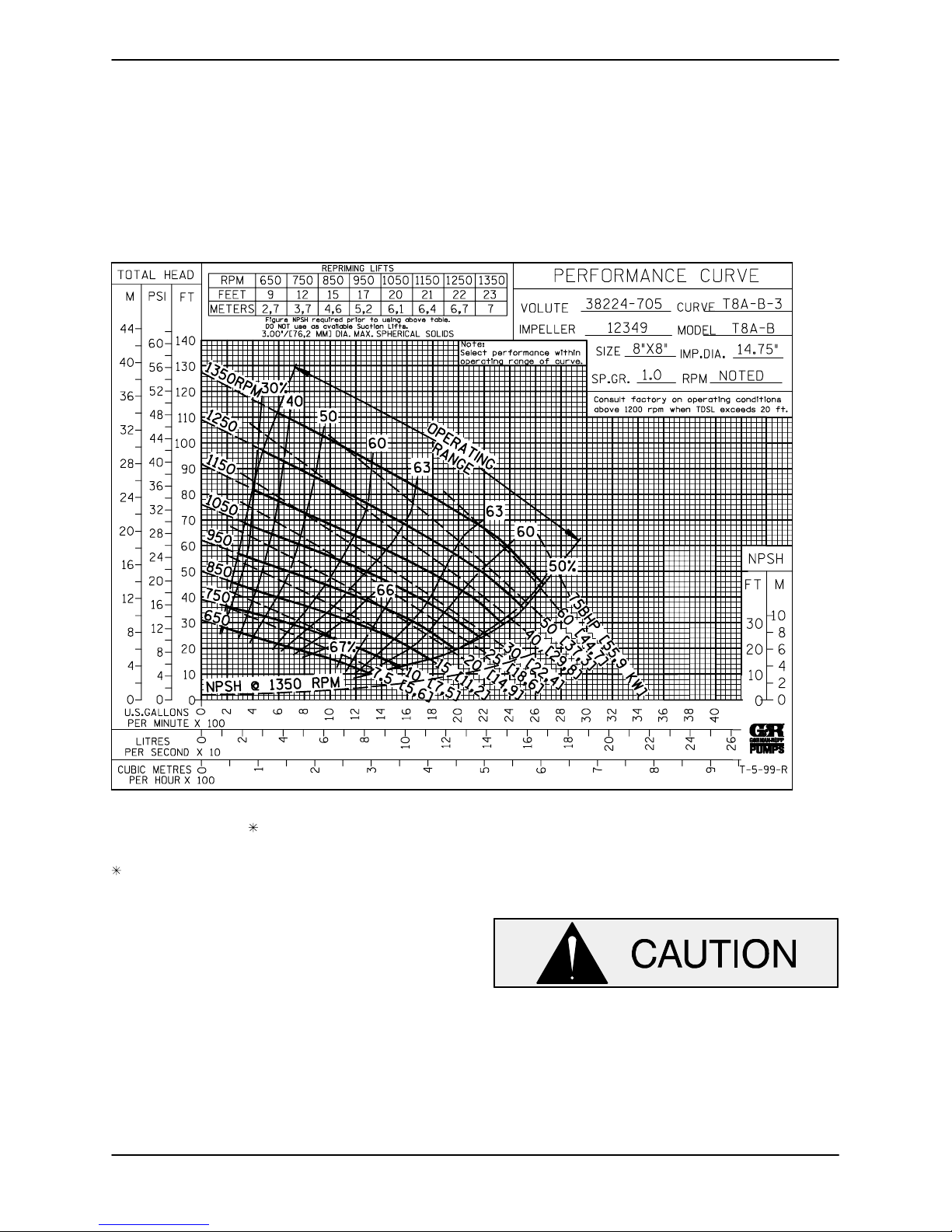
MAINTENANCE AND REPAIROF THEWEARING PARTSOFTHEPUMP WILLMAINTAINPEAKOPERATING PERFORMANCE.
STANDARD PERFORMANCE FOR PUMP MODEL T8A60-B
Based on 70_ F(21_ C) clear water at sea level
with minimum suctionlift. Sincepump installations
areseldomidentical,your performance may bedifference due to such factors as viscosity, specific
gravity, elevation, temperature, and impeller trim.
If your pump serial number is followed by an “N”,
your pump is NOT astandardproductionmodel.
MAINTENANCE & REPAIR PAGE E -- 1
Contact the Gorman-Rupp Company to verify performance or part numbers.
Pump speed and operating condition
points must be within the continuous performance range shown on the curve.
Page 23
OM--01930--03 TSERIES
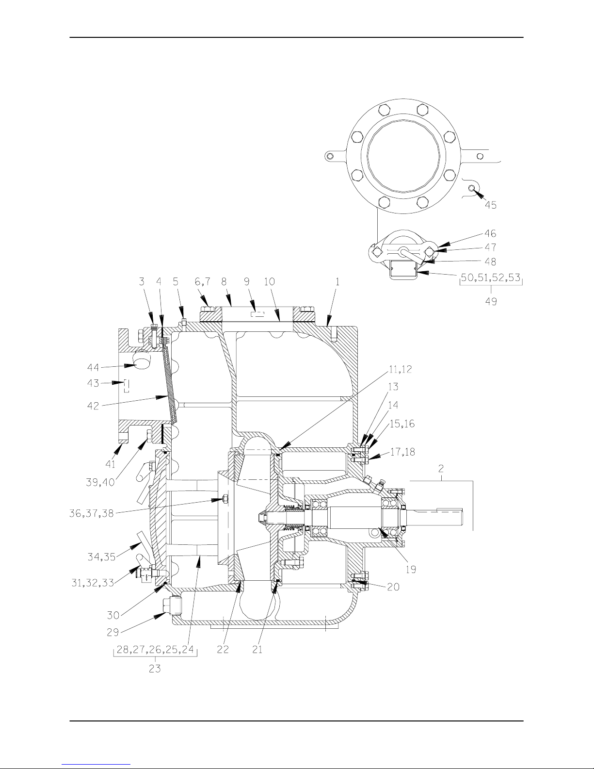
SECTION DRAWING
TOP VIEW
Figure 1. Pump Model T8A60---B
MAINTENANCE & REPAIRPAGE E -- 2
Page 24
TSERIES
OM--01930--03
PARTS LIST
Pump Model T8A60---B
(From S/N 905546 up)
Ifyour pump serialnumber is followedbyan “N”,your pumpis NOT a standard production model. Contact
the Gorman-Rupp Company to verify part numbers.
ITEM
PART NAME PART
NO.
NUMBER
MAT’L
CODE
QTY ITEM
NO.
PART NAME PART
NUMBER
MAT’L
CODE
QTY
1 PUMP CASING 38224-- -705 10010 1
2 REPAIR ROTATING ASSY 44163---129 1
3 CHECK VALVE PIN 12357 17010 1
4
SUCT FLANGE GSKT 12356G 19370 1
5 PIPE PLUG P04 15079 1
6 HEX HD CAPSCREW B1209 15991 8
7 LOCKWASHER J12 15991 8
8 DISCHARGE FLANGE 1759 10010 1
9 DISCHARGE STICKER 6588BJ --------- 1
10
DISCH FLANGE GSKT 1759GB 19370 1
11 NAME PLATE 38818---040 13990 1
12 DRIVE SCREW BM#04---03 17000 4
13
ROT ASSY SHIM SET 48261---056 --- ----- - REF
14 CASING RING 31281---016 15990 1
15 HEX HD CAPSCREW B0806 15991 6
16 LOCKWASHER J08 15991 6
17 HEX HD CAPSCREW B0805 15991 6
18 LOCKWASHER J08 15991 6
19 ROTATION DECAL 2613M --- ------ 1
20
BRG HOUSING O---RING S1914 --- - ----- REF
21
SEAL PLATE O-RING S1914 --- ------ REF
22
WEAR PLATE 12348A 10010 1
23
BACK COVER ASSY 42111---954 - ----- --- 1
24 ---BACK CVR PLATE NOT AVAILABLE 1
25 ---WARNING PLATE 2613EV 13990 1
26 ---DRIVE SCREW BM#04---03 17000 4
27 ---RELIEF VALVE 26662---005 --------- 1
28 ---WARNING DECAL 38816---302 --- --- --- 1
29 CASING DRAIN PLUG P32 10009 1
30
BACK COVER O---RING S1915 ----- ---- 1
31 BACK CVR HANDLE 12354 13010 2
32 HEX HD CAPSCREW B0604 15991 4
33 LOCKWASHER J06 15991 4
34 STUD C1212 15991 4
35 HAND NUT 10701A 15040 4
36 STUD C0808 15991 3
37 LOCKWASHER J08 15991 3
38 HEX NUT D08 15991 3
39 HEX HD CAPSCREW B1209 15991 8
40 LOCKWASHER J12 15991 8
41 SUCTION FLANGE 12356 10010 1
42
CHECK VALVE ASSY 46411---066 --- ------ 1
43 SUCTION STICKER 6588AG --------- 1
44 PIPE PLUG P20 10009 1
45 PIPE PLUG P04 15079 1
46 CLAMP BAR 38111---004 11010 1
47 MACHINE BOLT A1014 15991 2
48 CLAMP BAR SCREW 31912---009 15000 1
49 FILL CVR PLT ASSY 42111- --344 --- ------ 1
50 ---COVER PLATE NOT AVAILABLE 1
51 ---WARNING PLATE 38816---097 13990 1
52 ---DRIVE SCREW BM#04---03 17000 2
INDICATES PARTS RECOMMENDED FOR STOCK
Above SerialNumbersDo Not Apply To Pumps Made In Canada.
n KALREZr AND VITONt ARE PRODUCTS OF THE DUPONT CORP
L AFLASr IS A PRODUCT OF THE 3M CORP
53 ---GASKET 50G 19210 1
NOT SHOWN:
PIPE PLUG P04 15079 1
LUB DECAL 11421 --- ------ 1
PRIMING STICKER 6588AH --- --- --- 1
INSTRUCTION LABEL 2613DK ------ --- 1
WARNING DECAL 2613FE --- ------ 1
PIPE PLUG P08 15079 1
OPTIONAL:
DISASSEMBLYTOOL 12858 24000 1
ADI SEAL PLATE 12350 1102H 1
/F FLANGE KIT 48213---042 --- --- --- 1
---DISCHARGE 12799 10010 1
/FM DIN 2576 FLANGE KIT 48213---079 --- --- --- 1
---DISCHARGE 38642---610 10000 1
---SUCTION 38642---609 10000 1
/FM DIN 2527 FLANGE KIT 48213---083 --- --- --- 1
---DISCHARGE 38642---612 10000 1
---SUCTION 38642---611 10000 1
WEAR PLATE:
---STAINLESS STEEL 12348A 1718H 1
---SPECIAL W/WEAR RING 12348B --------- 1
ADI WEAR PLATE 12348A 1102H 1
CASING HEATERS:
---120V 47811---001 - ----- --- 1
---240V 47811---002 - ----- --- 1
CHECK VALVEASSY:
---NEO SOLID TYPE 46411---018 --- ---- -- 1
n ---VITON SOLID 46411---080 --- --- --- 1
n ---VITON BLOW---OUT 46411---090 ---- ----- 1
---EPDM 46411---115 - ----- --- 1
PRESS RELIEF VALVES:
---SEWAGE TYPE 46431---628 ------ --- 1
---STAINLESS STEEL 26662---101 --- ------ 1
HI TEMP SHUT---DOWN KITS:
--- 1 45 _F 48313---186 - ----- --- 1
--- 1 30 _F 48313---256 - ----- --- 1
--- 1 20 _F 48313---257 - ----- --- 1
AIR RELEASE VALVES:
--- 1 0# COM P S PRING GR P3 3 --- 07A --- --- --- 1
--- 2 5# COM P S PRING GR P3 3 --- 07 --- --- --- 1
--- 8 0# COM P S PRING GR P3 3 --- 07B --- --- --- 1
BACK COVER O-RING
n ---VITON 25154---458 ------ --- 1
MAINTENANCE & REPAIR PAGE E -- 3
Page 25
OM--01930--03 TSERIES
SECTION DRAWING
DRIVE END VIEW
SEAL AREA DETAIL
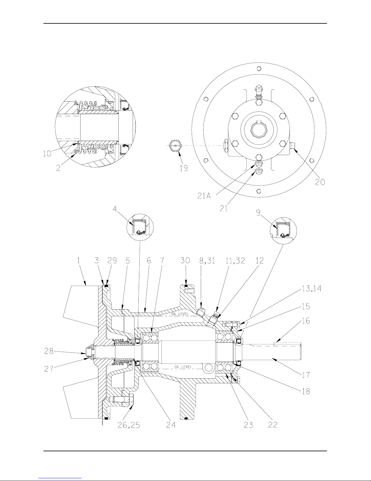
Figure 2. 44163---129 Repair Rotating Assembly
MAINTENANCE & REPAIRPAGE E -- 4
Page 26
TSERIES
PARTS LIST
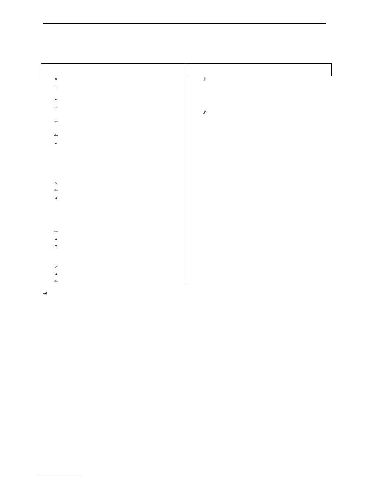
44163---129 Repair Rotating Assembly
ITEM
PART NAME PART
NO.
1 IMPELLER 12349 11000 1
SEAL ASSEMBLY 46513---154 --- ------ 1
2
3 SEAL PLATE 12350 10010 1
INBOARD OIL SEAL S1917 --- --- --- 1
4
SEAL PLATE GSKT 12350G 20000 1
5
6 BEARING HOUSING 38251---510 10000 1
INBRD BALL BEARING 23421---461 --------- 1
7
8 VENTED SEAL CAV PLUG 4823A 15079 1
9
OUTBOARD OIL SEAL S1917 --- ------ 1
IMPELLER SHIM SET 5091 17090 1
10
11 BRG HOUSING AIR VENT S1530 ------ --- 1
12 RED PIPE BUSHING AP0802 15079 1
13 HEX HD CAPSCREW B0605 1/2 15991 6
14 LOCKWASHER J06 15991 6
15 BEARING CAP 38322---415 10010 1
16
IMPELLER SHAFT KEY N0616 15990 1
IMPELLER SHAFT 38515---577 16000 1
17
RE TAIN IN G R IN G S2 15 --- --- --- 1
18
19 OIL LVL SIGHT GAUGE S1471 ----- --- - 1
20 PIPE PLUG P12 15079 1
21 SEAL CAV DRAIN PLUG P08 15079 1
21A BRG HSG DRAIN PLUG P08 15079 1
22
BR G H OUSING O -RING S3 33 --- --- --- 1
OUTBRD BALL BEARING 23422---412 --- -- ---- 1
23
SEAL SLEEVE O-RING 25152---026 ------ --- 1
24
25 HEX HD CAPSCREW B1006 15991 4
26 LOCKWASHER J10 15991 4
27
IMPELLER WASHER 10278 15030 1
IMPELLER CAPSCREW DM1004S 15991 1
28
SEAL PLATE O-RING S1914 -- ------- 1
29
NUMBER
MAT’L
CODE
QTY ITEM
OM--01930--03
PART NAME PART
NO.
BEARING HSG O-RING S1914 ------ --- 1
30
31 SHIPPING PLUG 11495B 15079 1
32 SHIPPING PLUG 11495B 15079 1
NOT SHOWN:
ROT ASSY SHIM SET 48261---056 --- ------ 6
ROTATION DECAL 2613M --------- 1
INSTRUCTION TAG 6588BU --- --- -- - 1
OPTIONAL:
ADI IMPELLER 12349 1102H 1
IMP CLEAN---OUT KIT 48783---004 --- ------ 1
SEAL FLUSH KIT 48783---510 ------ --- 1
STAINLESS STEEL PARTS:
IMPELLER WASHER 10278 17090 1
IMPELLER CAPSCREW DM1004S 17090 1
IMP SHAFT
(LESS SLEEVE) 38515---576 1706H 1
PERMALON COATED SEAL (USE W/SST SLEEVE
OR SOLID SST SHAFT) 46512---189 ------ --- 1
[LAFLAS SEAL (USE W/SST SLEEVE
OR SOLID SST SHAFT) 46512---193 ------ --- 1
[ METAL BELLOWS MECH SEAL ASSY (USE W/SST
SLEEVE OR SOLID SST SHAFT)
n ---(KALREZ) 46512---183 --------- 1
ROTATINGASSEMBLY O -RING
n ---VITON 25154---458 ------ --- 1
NUMBER
MAT’L
CODE
QTY
INDICATES PARTS RECOMMENDED FOR STOCK
[ OPTIONAL MECHANICAL SEAL(S) MUST BE USED WITH MECHANICAL SEAL SHAFT SLEEVE OR SOLID SST SHAFT.
n KALREZr AND VITONt ARE PRODUCTS OF THE DUPONT CORP.
L AFLASr IS A PRODUCT OF THE 3M CORP.
MAINTENANCE & REPAIR PAGE E -- 5
Page 27
OM--01930--03 TSERIES
PUMP AND SEAL DISASSEMBLY
AND REASSEMBLY
Most cleaning solvents are toxic and
flammable. Use themonly in a well ventilated area free from excessive heat,
sparks, and flame. Read and follow all
precautions printed on solventcontainers.
Review all SAFETY information in Section A.
Followthe instructions on alltags, labelanddecals
attached to the pump.
This pump requires littleservice due to its rugged,
minimum-maintenance design. However, if it becomesnecessarytoinspectorreplacethewearing
parts, followthese instructions which are keyed to
the sectional views (see Figures 1 and 2) and the
accompanying parts lists.
Forpower source disassembly and repair, consult
the literature supplied with the power source, or
contact your local power source representative.
Beforeattempting toopenorservic e the
pump:
1. Familiarize yourself with this man ual.
2. Disconnect or lock out the power
sourcetoensurethatthe pumpwill
remain inoperative.
3. Allow the pump to cool if overheated.
4. Check the temperature before
opening any covers, plates, or
plugs.
5. Close the suction and discharge
valves.
6. Vent the pump slowly and cautiously.
7. Drain the pump.
As described on the following page, this manual
willalert personnelto known procedures which require s pecial attention, to those which could damage equipment, and to those which could be dangerousto personnel. However,this manualcannot
possibly anticipate and provide detailed precautions for every situation that might occur during
maintenanceofthe unit.Therefore,itis the responsibilityof the owner/maintenance personnel to ensure that only safe, established maintenance proceduresare used, andthat anyproceduresnotaddressedinthismanualareperformedonly afterestablishingthat neitherpersonalsafetynorpumpintegrity are compromised by such practices.
Many service functions may be performed by
draining the pump and removing the back cover
assembly. If major repair is required, the piping
and/or power source must be disconnected. The
followinginstructionsassumecompletedisassembly is required.
Beforeattemptingtoservicethe pump, disconnect
or lock out the power source and take precautions
to ensure that it will remain inoperative. Close all
valves in the suction and discharge lines.
Use lifting and moving e quipment in
good repair and with adequate capacity
topreventinjuriesto personnel or damage to equipment.
Back Cover And Wear Plate Removal
(Figure 1)
Thewearplate(22)iseasilyaccessibleandmaybe
serviced by removing the back cover assembly
(23). Before attempting to service the pump, remove the pump casing drain plug (29) and drain
the pump. Clean and reinstall the drain plug.
Removethehandnuts (35)andpullthe back cover
andassembledwearplatefromthepumpcasing
(1). Inspect the wear plate, and replace it if badly
scoredandworn. Toremovethe wear plate, disengage the hardware (37 and 38).
Inspect the back cover O-ring (30) and replace it if
damaged or worn.
MAINTENANCE & REPAIRPAGE E -- 6
Page 28
TSERIES
OM--01930--03
Suction Check Valve Removal
(Figure 1)
If the check valve assembly (42) is to be serviced,
reach through the back coveropening,removethe
checkvalvepin(3)andpullthe completeassembly
from the suction flange (41).
NOTE
Further disassembly of the check valve is not required sinceitmust bereplacedas acompleteunit.
Individual parts are not sold separately.
Rotating Assembly Removal
(Figure 1)
Therotatingassembly(2)mayberemoved from either side of thepump casing (1); however,it is recommended that it be removed through the back
cover opening.
(Figure 2)
Theimpeller(1) shouldbe loosenedwhiletherotating assembly is still secured to the pump casing.
Before looseningthe impeller,remove thesealcavitydrain plug(21) anddrain theseal lubricant.This
willprevent the oil in the seal cavity from escaping
when the impeller is loosened. Clean and reinstall
the seal cavity drain plug.
Immobilize the impeller by wedging a block wood
between the vanes, and remove the impeller capscrew and washer (27 and 28). Install a lathe dog
onthe driveend ofthe shaft(17) withthe “V”notch
positioned over the shaft keyway.
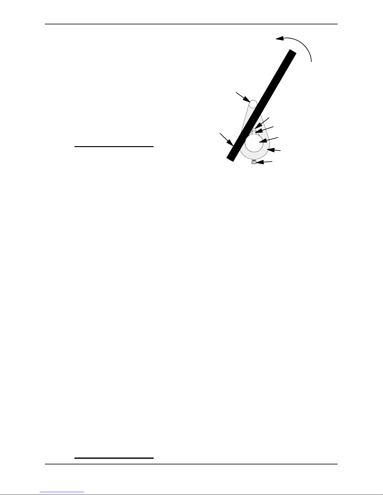
Withthe impellerrotationstillblocked,seeFigure3
and use a long piece of heavy bar stock to pry
against the arm of the lathe dog in a counterclockwise direction (when facing the drive end of the
shaft).Usecautionnottodamage the shaft orkeyway. When the impeller breaks loose, remove the
lathe dog and wood block.
NOTE
Donotremovetheimpelleruntiltherotatingassembly has been removed from the pump casing.
Turn
Counterclockwise
Lathe Dog Arm
“V” Notch
Heavy
Bar Stock
Figure 3. Loosening Impeller
(Figure 1)
Remove the inner hardware (17 and 18) from the
casing ring (14). Install three of the inner capscrews in the jacking holes in the casing ring, and
use them to press the rotating assembly into the
pump casing until the bearing housing is free.
Remove the jacking screws from the casing ring.
Remove the outer hardware (15 and 16) and shim
sets (13), and separate the casing ring from the
pumpcasing. Tieand tag the shim sets for ease of
reassembly.
An optional disassembly tool for removing and installing the rotating assembly is available from the
factory. If the tool is used, follow the instructions
packedwithit.Ifimprovisedtoolsare used,besure
they are heavy enough for safe use and will not
damage the pump.
After the rotating assembly is loosened, screw a
5/8-18 UNF X 16-inch long threaded rod into the
impeller shaft. Support the drive end with another
set of handles, or a length of pipe (1 13/16 inch
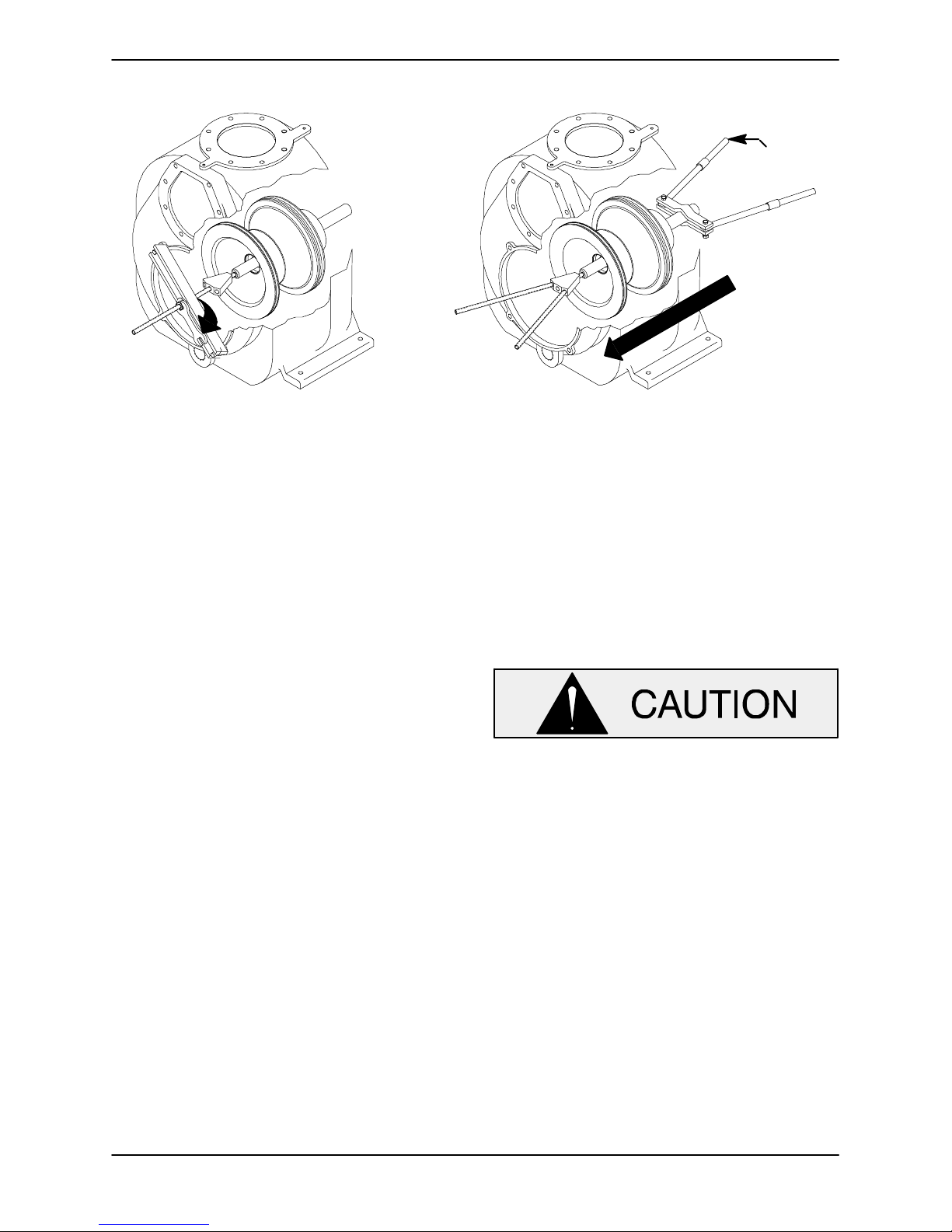
minimum I. D.), and slide the complete rotating assembly through the back cover opening (see Figure4).Movetherotatingassemblytoacleanwork
area before proceeding with disassembly.
Shaft Key
Impeller Shaft
Lathe Dog
Setscrew
MAINTENANCE & REPAIR PAGE E -- 7
Page 29
OM--01930--03 TSERIES
ADD PIPE
AS REQUIRED
Figure 4. Rotating Assembly Removal
Impeller Removal
(Figure 2)
Unscrew the impeller (1) in a counterclockwise direction when facing theimpeller.Use caution when
unscrewing the impeller; tension on the shaft seal
spring will be released as the impeller is removed.
Remove the impelleradjusting shims (10). Tieand
tag the shims or measure and record their thickness for ease of reassembly.
Seal Removal
(Figure 2)
Slide the integral shaft sleeve and rotating portion
of the seal off the shaft as a unit.
Usea pairofstiff wireswith hooked endsto remove
the stationary element and seat.
An alternate method of removing the stationary
seal components is to remove the hardware (25
and 26) and separate the seal plate(3) and gasket
(5) from the bearing housing (6). Position the seal
plate on a flat surface with the impeller side down.
Use awoodendowel or other suitable tool topress
on the back side of the stationary seat until the
seat, O-rings and stationary element can be removed.
Remove the shaft sleeve O-ring (24).
If no further disassembly is required, refer to Seal
Installation.
Shaft and Bearing Removal and Disassembly
(Figure 2)
When the pump is properly operated and maintained,the bearing housingshouldnot requiredisassembly. Disassemble the shaft and bearings
only when there is evidence of wear or damage.
Shaft and bearing disassembly in the field
is not recommended. These operations
should be performed only in a properly-equipped shop by qualified personnel.
Remove the bearing housing O-ring (30).
Remove the bearing housing drain plug (21A) and
drain the lubricant. Clean and reinstall the drain
plug.
Disengage thehardware (13and 14) and slide the
bearing cap(15), O-ring(22) and oilseal (9) off the
shaft. Remove the O-ring, and press the oil seal
from the bearing cap.
Place a block of wood against the impeller end of
the shaft and tap the shaft and assembled bearings (7 and 23) from the bearing housing.
After removing the shaft and bearings, clean and
inspect the bearings in place as follows.
MAINTENANCE & REPAIRPAGE E -- 8
Page 30
TSERIES
OM--01930--03
Ifbearing replacementis required,removethe outboard bearing retaining ring (18), and use a bearing puller to remove the bearings from the shaft.
To prevent damage during removal from
the shaft, it is recommended that bearings
be cleaned and inspected in place.Itis
strongly recommended that the bearings
be replaced any time the shaft and bearings are removed.
Clean the bearing housing, shaft and all component parts (except the bearings) with a soft cloth
soaked in cleaning solvent. Inspect the parts for
wear or damage and replace as necessary.
Most cleaning solvents are toxic and
flammable. Use them onlyin a well-ventilated area free from excessive heat,
sparks, and flame. Read and follow all
precautions printed on solventcontainers.
Clean the bearings thoroughly in fresh cleaning
solvent.Dry the bearings with filteredcompressed
air and coat w ith light oil.
Press the inboard oil seal (4) from the bearing
housing.
Shaftand BearingReassembly and Installation
(Figure 2)
Clean the bearing housing, shaft and all component parts (except the bearings) with a soft cloth
soaked in cleaning solvent. Inspect the parts for
wear or damage as necessary.
Most cleaning solvents are toxic and
flammable. Use them onlyin a well-ventilated area free from excessive heat,
sparks, and flame. Read and follow all
precautions printed on solventcontainers.
Inspect the shaft for distortion, nicks or scratches,
or for thread damage on the impeller end. Dress
small nicks andburrswith a fine file or emery cloth.
Replace the shaft if defective.
Bearings must be kept free of all dirt and
foreign material. Failure to doso will greatly shorten bearing life. Do not spin dry
bearings. This may scratch the balls or
races and cause premature bearing failure.
Rotate the bearings by hand to check for roughnessorbinding and inspect the bearing balls.If rotation is rough or the bearing balls are discolored,
replace the bearings.
The bearing tolerances provide a tight press fit
onto the shaft and a snug slip fit into the bearing
housing. Replace the bearings, shaft, or bearing
housing if the proper bearing fit is not achieved.
MAINTENANCE & REPAIR PAGE E -- 9
To prevent damage during removal from
the shaft, it is recommended that bearings
be cleaned and inspected in place.Itis
strongly recommended that the bearings
be replaced any time the shaft and bearings are removed.
The bearings may be heated to ease installation.
An induction heater, hot oil bath, electric oven, or
hotplatemaybeusedtoheatthebearings.Bearings should never be heated with a direct flame or
directly on a hot plate.
NOTE
Ifahotoil bathisused toheatthebearings, both the
oil and the container must be absolutely clean. If
the oil has been previously used, it must be thor-
oughly filtered.
Page 31
OM--01930--03 TSERIES
Heat the bearings to a uniform temperature no
higher than250_F(120_C), andslidethebearings
onto the shaft, one at a time, until they are fully
seated. This s hould be done quickly, in one continuous motion, to prevent the bearings from cooling and sticking on the shaft.
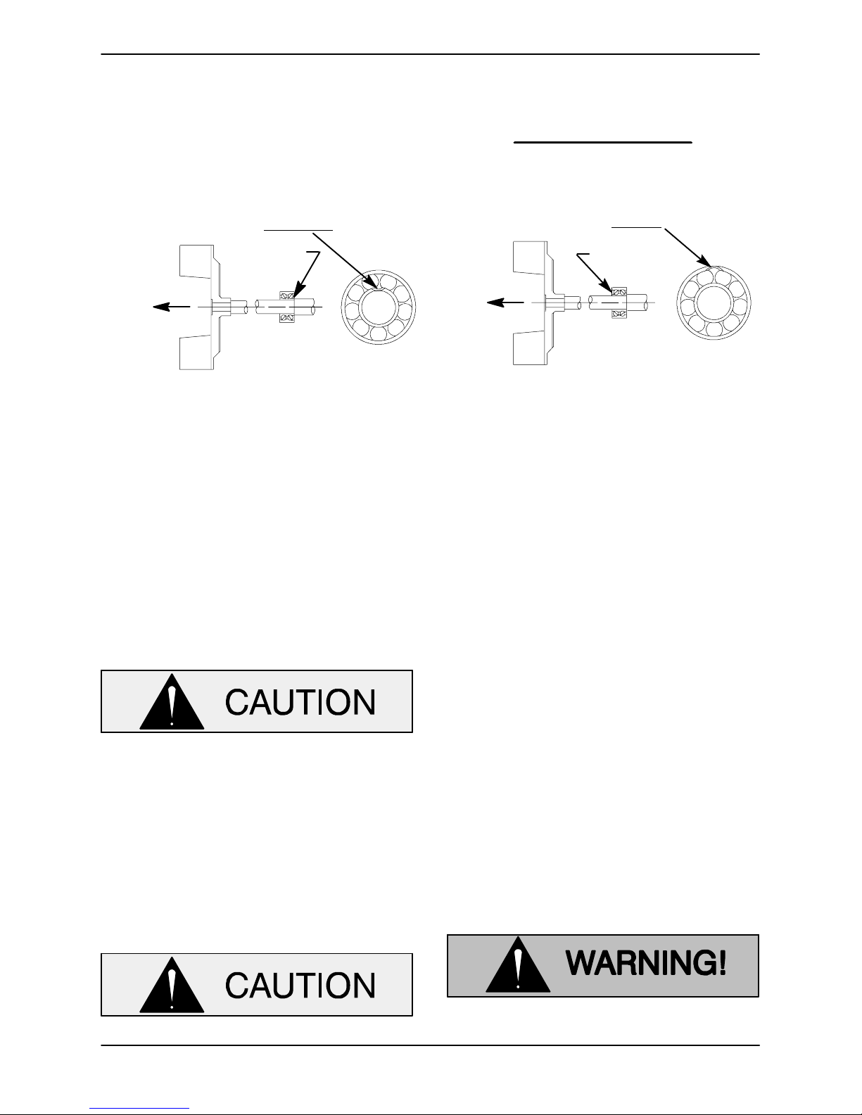
BALL LOADING
GROOVE POSITIONED
AWAY FROM
LOADING
GROOVE
DIRECTIONOF
THRUST
INSTALLATION OF NEW DEPARTURE OR
BCA/FEDERAL MOGAL 5300W SERIES BEARINGS
(OPEN OR ENCLOSED IMPELLERS)
IMPELLER
Figure 4. Inboard Bearing Positioning
Afterthe bearingshave beeninstalled and allowed
to cool,check to ensure that they have not moved
away from the shaft shoulders in shrinking. If
movement has occurred, use a suitably sized
sleeve and a press to reposition the bearings
against the shaft shoulders.
If heating the bearings is not practical, use a suitablysizedsleeve,and an arbor(orhydraulic)press
to install the bearings on the shaft.
When installing the bearings onto the
shaft, never press or hit against the outer
race, balls, or ball cage. Press only on the
inner race.
NOTE
Positionthe inboardbearing(7)on theshaftasindicated by the following illustration.
BALL LOADING
DIRECTIONOF
THRUST
INSTALLATIONOF MRC/SKF 5300M OR
(OPEN OR ENCLOSED IMPELLERS)
GROOVE POSITIONED
TOWARD
LOADING
GROOVE
FAFNIR 5300W SERIES BEARINGS
IMPELLER
the bearing bore, push against the outer
race. Never hit the balls or ball cage.
Position the inboard oil seal (4) over the shaft with
the lip positioned as shown in Figure 2. B e careful
not to damage the oilseal lip on the shaft threads.
Pressthe oilseal into the bearinghousing until the
face is just flush with the machined surface on the
housing.
Press the outboard oil seal (9) into thebearing cap
(15) with the lip positioned as shown in Figure 2.
Replace the bearing cap O-ring (22), and secure
the bearing cap with thehardware (13 and 14). Be
careful not to damage the oil seal lip on the shaft
keyway.
Lubricate the bearing housing as indicated in LU-
BRICATION.
Secure the outboard bearing on the shaft with the
bearing retaining ring (18).
Slide the shaft and assembled bearings into the
bearing housing until the retaining ring on the outboard bearing seats against the bearing housing.
When installing the shaftand bearings into
Seal Reassembly and Installation
(Figures 2, 5, 6 and 7)
Cleanthe seal cavity and shaft witha cloth soaked
in fresh cleaning solvent.
Most cleaning solvents are toxic and
flammable. Use them onlyin a well-ven-
MAINTENANCE & REPAIRPAGE E -- 10
Page 32
TSERIES
tilated area free from excessive heat,
sparks, and flame. Read and follow all
precautions printed on solventcontainers.
Cleanthe seal cavity and shaft witha cloth soaked
in fresh cleaning solvent. Inspect the stationary
seat bore in the seal plate for dirt, nicks and burrs,
andremoveany that exist.Thestationaryseatbore
must be completely clean before installing the
seal.
OM--01930--03
A new seal assembly should be installed
any time the old seal is removed from the
pump. Wear patterns on the finished faces
cannot be realigned during reassembly.
Reusing an old seal could result in premature failure.
To ease installation of the seal, lubricate the shaft
sleeve O-ring and the external stationary seat Oringwithaverysmallamountoflightlubricatingoil.
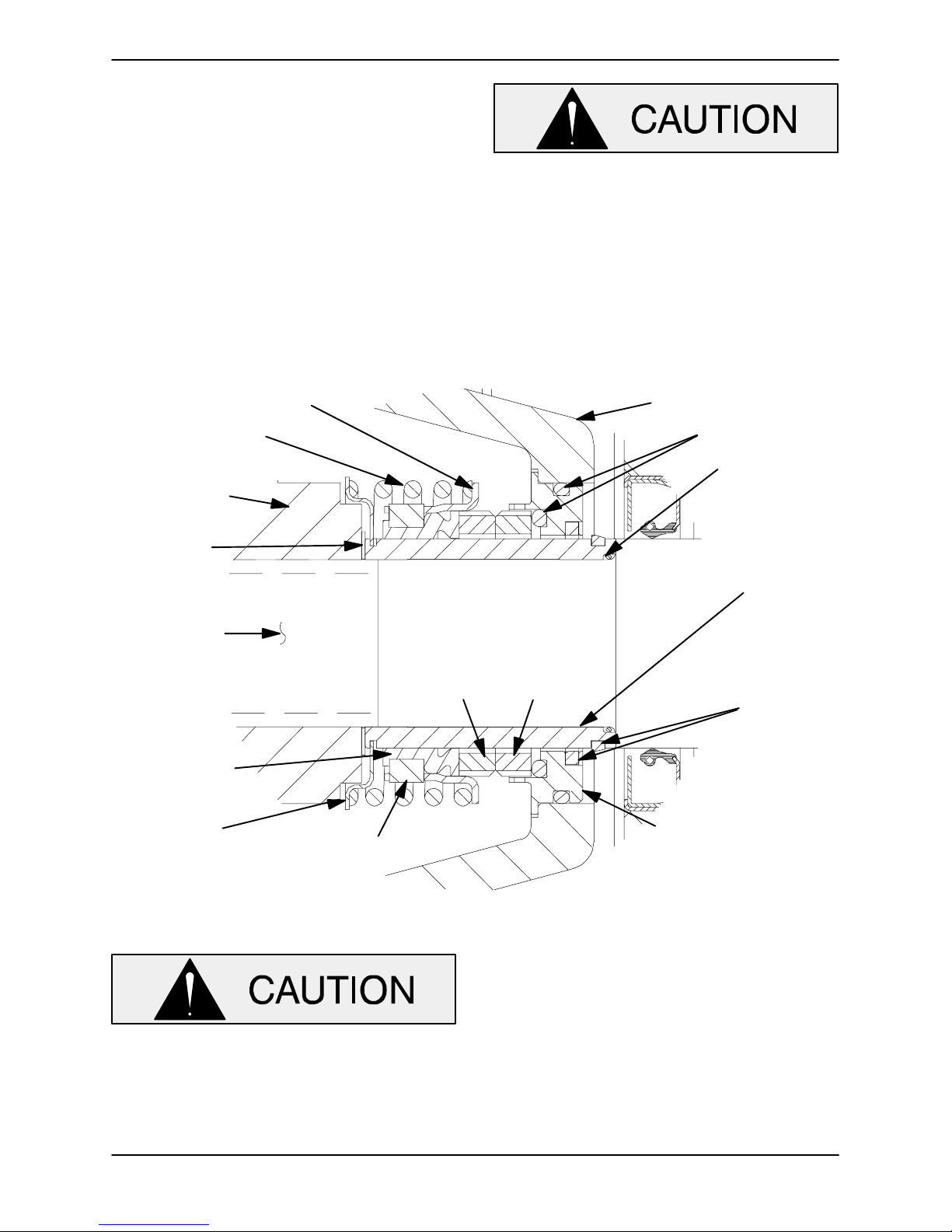
See Figure 5 for seal part identification.
IMPELLER
IMPELLER
SHIMS
IMPELLER
SHAFT
BELLOWS
SPRING
CENTERING
WASHER
RETAINER
SPRING
ROTATING
ELEMENT
DRIVE BAND
SEAL PLATE
O-RINGS
SLEEVE
O-RING
INTEGRAL
SHAFT
SLEEVE
STATIONARY
ELEMENT
SHEAR
RING
(SHEARED)
STATIONARY
SEAT
This seal is not designed for operation at
temperatures above160
_F(71_C). Donot
use at higher operating temperatures.
If the seal plate w as removed, install the seal plate
gasket (5). Position the seal plate over the shaft
MAINTENANCE & REPAIR PAGE E -- 11
Figure 5. 46513--154 Seal Assembly
and secure it to the bearing housingwith the hardware (25 and 26).
To prevent damaging the shaft sleeve O-ring (24)
ontheshaftthreads,stretchtheO-ringoverapiece
oftubing1-9/16-inchI.D.x1-13/16-inchO.D.x 2-incheslong(14mmx21mmx51mm). Slidethetube
over the s haft threads, then slide the O-ring offthe
tube and onto t he shaft. Remove the tube, and
Page 33
OM--01930--03 TSERIES
continue to slide the O-ring down the shaft until it
seats against the shaft shoulder.
When installing a new cartridge seal assembly,
remove the seal from the container, and remove
the mylar storage tabs from between the seal
faces.
New cartridge seal assemblies are
equipped withmylar storagetabsbetween
thesealfaces.Thesestoragetabs mustbe
removed before installing the seal.
Lubricate the external stationary seat O-ring with
light oil.Slidethe seal assemblyontothe shaft until
the external stationary seat O-ring engages the
bore in the seal plate.
Cleanand inspect the impeller as described inIm -
pellerInstallationand Adjustment.Install the full
set of impeller shims (10) provided with the seal,
and screw the impeller onto the shaft until it is
seated against the seal (see Figure 6).
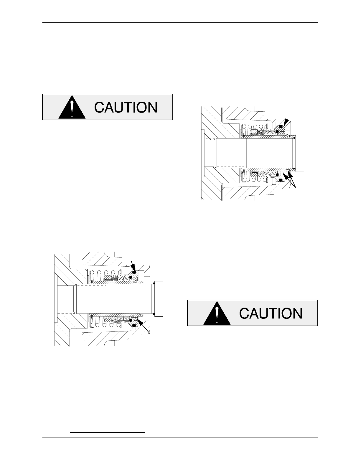
O-RING ENGAGED
WITH SEAL PLATE
BORE
As the stationary seat becomes fully seated, the
seal spring compresses, and the shaft sleeve w ill
break the nylon shear ring. This allows the sleeve
to slide down the shaft until seated against the
shaftshoulder.Continuetoscrew the impelleronto
the shaft until the impeller, shims, and sleeve are
fullyseated against the shaft shoulder (see Figure
7).
STATIONARY SEAT
FULLY SEATED IN
SEAL PLATE BORE
SHEAR RING
(SHEARED)
Figure 7. Seal Fully Installed
Measure the impeller-to-seal plate clearance, and
remove impeller adjusting shims t o obtain the
proper clearance as described in Impeller Instal-
lation and Adjustment.
If necessary to reuse an old seal in an emer-
gency, carefully separate the rotating and stationary seal faces from the bellows retainer and stationary seat.
Figure 6. Seal Partially Installed
Continue to screw t he impeller ontothe shaft. This
will press the stationary seat into the seal plate
bore.
NOTE
Afirm resistancewill befelt as theimpellerpresses
the stationary seat into the seal plate bore.
SHEAR RING
(UNSHEARED)
A new seal assembly should be installed
any time the old seal is removed from the
pump. Wear patterns on the finished faces
cannot be realigned during reassembly.
Reusing an old seal could result in premature failure.
Handlethe seal parts w ith extreme care to prevent
damage. Be careful not to contaminate precision
finished faces; even fingerprints on the faces can
shortenseallife.If necessary,cleanthefaceswitha
non-oilbased solvent and a clean, lint-free tissue.
Wipe lightly in a concentric pattern to avoid
scratching the faces.
MAINTENANCE & REPAIRPAGE E -- 12
Page 34
TSERIES
OM--01930--03
Carefully wash all metallic parts in fresh cleaning
solvent and allow to dry thoroughly.
Do not attempt to separate the rotating
portion of the seal from the shaft sleeve
when reusing an old seal. The rubber bellows will adhere to the sleeve during use,
and attempting to separate them could
damage the bellows.
Inspect the seal components for wear, scoring,
grooves,andother damage that mightcause leakage. Inspect the integral shaft sleeve for nicks or
cuts on either end. Ifany componentsare worn, or
the sleeve is damaged, replace the complete seal;
never mix old and new seal parts.
Installthe stationary seal element in the stationary
seat. Press this stationary subassembly into the
seal plate bore until it seats squarely against the
bore shoulder. A push tube made from a piece of
plastic pipe would aid this installation. The I.D. of
the tube should be slightly larger than the O.D. of
the shaft sleeve.
Slide t he rotating portion of the seal (consisting of
the integral shaft sleeve, spring centering washer,
spring, bellows and retainer,and rotatingelement)
onto the shaft until the seal faces contact.
Proceed with Impeller Installation and Adjust-
ment.
Impeller Installation and Adjustment
to the shaft, making future removal difficult
or impossible without damage to the impellerorshaft.
Install the same thickness of impeller adjusting
shims (10) as previously removed. Apply ‘NeverSeez’ or equivalent to the shaft threads and screw
the impeller onto the shaft until tight. Be sure the
spring centering washer seats squarely over the
shoulder on the back side of the impeller .
NOTE
At the slightest sign of binding, immediately back
the impeller off, and check the threads for dirt. Do
not try to force the impeller onto the shaft.
A clearance of .025 to .040 inch (0,64 to 1,02 mm)
between the impeller and the seal plate is recommended for maximum pump efficiency. Pre-load
the shaft in the direction of the impeller,and
measure this clearance; add or remove impeller
adjusting shims as required.
NOTE
If the rotating assembly has been installed i n the
pump casing, this clearance may be measured by
reaching through the priming port with a feeler
gauge.
Afterthe rotating assembly is installedin thepump
casing, coat the threads of the impeller capscrew
(28) with ‘Never-Seez’ or equivalent compound,
and install theimpellerwasher (28) and capscrew;
torque the capscrew to 90 ft. lbs. (1080 in. lbs. or
12,4 m. kg.).
(Figure 2)
Inspect the impeller , and replace it if cracked or
badly worn. Inspect the impellerand shaft threads
for dirt or damage, and clean or dress the threads
as required.
The shaft and impeller threads must be
completelycleanbeforereinstalling theimpeller. Even the slightest amount of dirt on
thethreads can causethe impeller to seize
MAINTENANCE & REPAIR PAGE E -- 13
Rotating Assembly Installation
(Figure 1)
NOTE
If the pump has been completely disassembled, it
is recommended that the suction check valve and
back cover assembly be reinstalled at this point.
Thebackcoverassemblymustbeinplacetoadjust
the impeller face clearance.
Install the bearing housing and seal plate O-rings
(20 and 21), and lubricate them with light grease.
Ease the rotating assembly into the pump casing
Page 35

OM--01930--03 TSERIES
using the installation tool. Be careful not to damage the O-rings.
Secure the pump casing ring (14) to the rotating
assembly with the inner hardware (17 and 18).
NOTE
The inner capscrews are 1/4 inch (3,2 mm)shorter
than the outer capscrews.
Install an equal thickness of rotating assembly
shims(13)underthepumpcasingring,andsecure
the ring to the pump casing with the outer hardware (15 and 16).
A clearance of .010 to .020 inch (0,25 to 0,51 mm)
betweentheimpellerand the wearplateisalsorecommended for maximum pump efficiency. This
clearance can be obtained by removing an equal
amount of shims from each rotating assembly
shimsetuntilthe impellers crapes againstthewear
plate when the shaft is turned by hand. Preload
the shaft in the direction of the impeller when
checking this clearance. After the impeller
scrapes,addapproximately.010inch(0,25 mm)of
shims to each shim set.
theadaptorwiththeflangehole,andsecuretheassembly with the check valve pin (3).
NOTE
If the suction or discharge flanges were removed,
replace the respective gaskets, apply ‘Permatex
Aviation No. 3 Form-A-Gasket’ or equivalent compound to the mating surfaces, and secure them to
the pump casing with the attaching hardware.
Back Cover Installation
(Figure 1)
If the wear plate (22) was removed for replacement, carefully center the new wear plate on the
backcoverandsecure it withthehardware (37and
38). The wear plate must be concentric to prevent
binding when the back cover is installed.
Replacetheback cover O-ring(30),andlubricateit
withagenerousamountofNo.2grease.Cleanany
scale or debris from the contacting surfaces in the
pumpcasingthat mightinterfereorprevent a good
seal with the back cover. Slide the back cover assembly into the pump casing. Be sure the wear
plate does not bind against the impeller.
NOTE
Analternatemethodof adjusting thisclearanceis to
reach through the suction port with a feeler gauge
and measure the gap. Add or subtract rotating assembly shims accordingly.
Suction Check Valve Installation
(Figure 1)
Inspect the check valve(42), and replaceit if badly
worn.
NOTE
The check valve assembly must be replaced as a
complete unit. Individual parts are not sold separately.
Reach through the back cover opening with the
check valve, and position the check valve adaptor
inthemountings lot inthesuctionflange(41).Align
NOTE
To ease future disassembly, apply a film of grease
or ‘Never-Seez’ on the back cover shoulder , or any
surface which contacts the pump casing. This action will reduce rust and scale build -up.
Secure the back cover assembly by tightening the
hand nuts (35) evenly. Do not over-tighten the
hand nuts; they shouldbe just tight enough to ensure a good seal at the back cover shoulder. Be
sure the wear plate does not bind against the casing.
PRESSURE RELIEF VALVE
MAINTENANCE
(Figure 1)
The back cover is equipped with a pressure relief
valve(27)to provideadditionalsafety for the pump
and operator (refer to Liquid Temperature And
Overheating in OPERATION).
MAINTENANCE & REPAIRPAGE E -- 14
Page 36
TSERIES
OM--01930--03
Itis recommended thatthepressurerelief valveas sembly be replaced at each overhaul, or any time
thepumpoverheatsandactivatesthe valve.Never
replace this valve with a substitute w hich has not
been specified or provided by the Gorman-Rupp
Company.
Periodically, the valve should be removed for inspection and cleaning. When reinstalling the relief
valve, apply ‘Loctite Pipe Sealant With Teflon No.
592’, or equivalent compound, on the relief valve
threads. Position the valve as shown in Figure 1
with the discharge port pointing down.
Final Pump Assembly
(Figure 1)
Install the shaft key (16, Figure 2) and reconnect
the power source. Be sure to install any guards
used over the rotating members.
ounces(2,7 liters) of SAENo. 30 non-detergent oil,
ortoaleveljust belowt he tappedventedplughole.
Cleanandreinstalltheventedplug.Maintaintheoil
at this level.
Bearings
(Figure 2)
The bearing housing was fully lubricated when
shipped from the factory. Check the oil level regularlythroughthesight gauge(19)and maintainit at
the middle of the gauge. When lubrication is required, add SAE No. 30 non-detergent oilthrough
theholefortheairvent(11).Donot over-lubricate.
Over-lubrication can cause the bearings to overheat, resulting in premature bearing failure.
NOTE
Thewhitereflectorin thesightgaugemust beposi tioned horizontally to provide proper drainage.
Do not operate the pump without the
guards in place over the rotating parts.
Exposed rotating parts can catch clothing, fingers,or tools,causing severe injury to personnel.
Installthe suction anddischarge linesand openall
valves. Makecertainthat allpiping connections are
tight, properly supported and secure.
Be sure thepumpandpowersourcehavebeen
properly lubricated, see LUBRICATION.
Remove the fill cover assembly (49) and fill the
pump casing with clean liquid. Reinstall the fill
coverandtightenit. Refer to OPERATION,Section
C, before putting the pump back into service.
LUBRICATION
Under normal conditions, drain the bearing housingonce each yearand refillwith approximately32
ounces (0,95 liter) clean oil. Change the oil more
frequently if the pump is operated continuouslyor
installedin an environmentwith rapid temperature
change.
Monitor the condition of the bearing lubricantregularly for evidenceof rust or moisture condensation. This is especially important in areas where variable hot and
cold temperatures are common.
Forcold w eather operation,consultthefactoryora
lubricant supplier for the recommended grade of
oil.
Seal Assembly
(Figure 2)
Before starting the pump, remove the vented plug
(8) and fill the seal cavity with approximately 90
MAINTENANCE & REPAIR PAGE E -- 15
Power Source
Consult the literature supplied with the power
source, or contact your local power source representative.
Page 37

For U.S. and International Warranty Information,
Please Visit www.grpumps.com/warranty
or call:
U.S.: 419−755−1280
International: +1−419−755−1352
For Canadian Warranty Information,
Please Visit www.grcanada.com/warranty
or call:
519−631−2870
THE GORMAN-RUPP COMPANY D MANSFIELD, OHIO
GORMAN-RUPP OF CANADA LIMITED D ST. THOMAS, ONTARIO, CANADA
 Loading...