

Page 1
CD
OM-04326---OE02
June 16, 1997
INSTALLATION, OPERATION,
AND MAINTENANCE MANUAL
WITH P ARTS LIST
TSERIESPUMPS
MODEL
T8A3 --- B --- F4L
THE GORMAN-RUPP COMPANY D MANSFIELD, OHIO
GORMAN-RUPP OF CANADA LIMITED D ST.THOMAS, ONTARIO, CANADA Printed in U.S.A.
ECopyright by the Gorman-Rupp Company
Page 2

The engine exhaust from this
product contains chemicals
known to the State of California to
cause cancer, birth defects or
other reproductive harm.
Page 3

TABLE OF CONTENTS
INTRODUCTION PAGE I --- 1.................................................
WARN ING S --- S ECT ION A PA G E A --- 1.......................................
IN STA L LAT ION --- SEC T IO N B PA G E B --- 1....................................
Pump Dimensions PAGE B --- 1.....................................................
PREINSTALLATION INSPECTION PAGE B --- 2............................................
Battery Specifications And Installation PAGE B --- 2....................................
POSITIONING PUMP PA GE B --- 2.......................................................
Lifting PA GE B --- 2.................................................................
Mounting PA GE B --- 3.............................................................
Clearance PA GE B --- 3.............................................................
SUCTION AND DISCHARGE PIPING PAGE B --- 3.........................................
Materials PA GE B --- 3..............................................................
Line Configuration PAGE B --- 3......................................................
Connections to Pump PAGE B --- 3..................................................
Gauges PA GE B --- 3...............................................................
SUCTION LINES PAGE B --- 3...........................................................
Fittings PA GE B --- 3...............................................................
Strainers PA GE B --- 3..............................................................
Sealing PAGE B --- 4...............................................................
Suction Lines In Sumps PAGE B --- 4.................................................
Suction Line Positioning PAGE B --- 4................................................
DISCHARGE LINES PA GE B --- 5........................................................
Siphoning PAGE B --- 5.............................................................
Valves PA GE B --- 5................................................................
Bypass Lines PA GE B --- 5..........................................................
AUTOMATIC AIR RELEASE VALVE PAGE B --- 6...........................................
Theory of Operation PAGE B --- 6....................................................
Air Release Valve Installation P AGE B --- 7............................................
ALIGNMENT PAGE B --- 8..............................................................
OPER AT IO N --- S E CT I ON C PA G E C --- 1......................................
PRIMING PA GE C --- 1.................................................................
STARTING PA GE C --- 1................................................................
OPERATION PA GE C --- 1..............................................................
Lines W ith a Bypass PAGE C --- 2....................................................
Lines Without a Bypass PAGE C --- 2.................................................
Leakage PAGE C --- 2..............................................................
Liquid Temperature And Overheating PAGE C --- 2.....................................
Strainer Check PAGE C --- 2.........................................................
Pump Vacuum Check PAGE C --- 3..................................................
STOPPING PA GE C --- 3................................................................
Cold Weather Preservation PAGE C --- 3..............................................
BEARING TEMPERATURE CHECK PAGE C --- 3..........................................
TR OUB LES HOO TI NG --- S EC T IO N D PA G E D --- 1..............................
i
Page 4

TABLE OF CONTENTS
(continued)
PUMP MAINTENANCE AND REPAIR --- SECTION E PAGE E --- 1................
PERFORMANCE CURV E PA GE E --- 1......................................................
PARTS LISTS:
Pump Model PA GE E --- 3..........................................................
Pump End Assembly PAGE E --- 5...................................................
Repair Rotating Assembly PAGE E --- 7...............................................
PUMP AND SEAL DISASSEMBLY AND REASSEMBLY PAGE E --- 8.........................
Back Cover And Wear Plate Removal PAGE E --- 8.....................................
Suction Check Valve Removal PAGE E --- 9...........................................
Pump Casing Removal PAGE E --- 9.................................................
Rotating Assembly Removal PAGE E --- 9.............................................
Impeller Removal PAGE E --- 10......................................................
Seal Removal and Disassembly PAGE E --- 10..........................................
Shaft and Bearing Removal and Disassembly PAGE E --- 11.............................
Shaft and Bearing Reassembly and Installation P AGE E --- 11............................
Seal Reassembly and Installation P AGE E --- 13........................................
Impeller Installation PAGE E --- 14.....................................................
Rotating Assembly Installation PAGE E --- 15...........................................
Pump Casing Installation PAGE E --- 15................................................
Suction Check Valve Installation P AGE E --- 16.........................................
Back Cover Installation P AGE E --- 16.................................................
PRESSURE RELIEF VALVE MAINTENANCE PAGE E --- 16..................................
Final Pump Assembly PAGE E --- 17..................................................
LUBRICATION PAGE E --- 17.........................................................
Seal Assembly PAGE E --- 17.........................................................
Bearings PAGE E --- 17..............................................................
Engine PA GE E --- 17................................................................
ii
Page 5
TSERIES
OM--04326
INTRODUCTION
This Installation, Operation, and Maintenance
manual is designed to help you achieve the best
performance and longest life from your GormanRupp pump.
This pump is a T Series, semi-open impeller, selfpriming centrifugal model with a suction check
valve. The pump is flex-coupled to a gearbox driven by a Deutz F4L diesel engine. It is designed for
handling sewage, wastewater, trash and slurries
containinglarge entrained solids. The basicmaterialofconstructionforwettedpartsisgrayiron,w ith
ductile iron wearing parts and alloy steel impeller
shaft.
If there are any questions regarding the pump or
trailer application which are not covered in this
manual or in other literature accompanying this
unit, please contact your Gorman-Rupp distributor, or write:
The Gorman-Rupp Company
P.O. Box 1217
Mansfield, Ohio 44901--1217
or
Gorman-Rupp of Canada Limited
70 Burwell Road
St. Thomas, Ontario N5P 3R7
cording to all national, local and industry standards.
The following are used t o alert maintenance personnel toprocedures which requirespecialattention, tothose which coulddamage equipment,and
to those which could be dangerous to personnel:
Immediate hazards whichWILL resultin
severe personal injury or death. These
instructions describe the procedure required and the injury which will result
from failure to follow the procedure.
Hazards or unsafe practices which
COULDresult in severe personal injury
or death. These instructions describe
the procedure required and the injury
which could result from failure to follow
the procedure.
For information or technical assistance on the engine, contact the engine manufacturer’s local
dealer or representative.
Because pump installations are seldom identical,
this manual cannot possibly provide detailed instructions and precautions for every aspect of
each specific application. Therefore, it is the responsibility of the owner/installer of the pump to
ensure that applications not addressed in this
manual are performed only after establishing that
neither operator safety norpump integrity are compromised by the installation. Pumps and related
equipment must be installed and operated ac-
HazardsorunsafepracticeswhichCOULD
result in minor personal injury or product
or property damage. These instructions
describe the requirements and the possibledamage which couldresult fromfailure
to follow the procedure.
NOTE
Instructions to aid in installation, operation,and
maintenance, or which clarify a procedure.
PAGE I -- 1INTRODUCTION
Page 6
TSERIES
OM--04326
SAFETY - SECTION A
This information applies to T Series engine driven pumps. Refer to the manual
accompanying the engine before attempting to begin operation.
Because pump installations are seldom
identical, thi s manual cannot possibly
provide detailed instructions and precautions for each specific application.
Therefore, it is the owner/installer’s responsibility to ensure that applications
not addressed in this manual are performed only
after establishing that neither operator safety nor pump integrity
are compromised by the installation.
Beforeattempting toopenorservic e the
pump:
maydamagethepumpor endanger personnel as a result of pump failure.
Use lifting and moving equipment in
good repair and with adequate capacity
topreventinjuriesto personnel or damage to equipment. Suction and discharge hoses and piping must be removed from the pump before lifting.
Afterthe pump hasbeen installed,make
certain that the pump and all piping or
hose connections are tight, properly
supportedand securebeforeoperation.
1. Familiarize yourself with this manual.
2. Switch off the engine ignition and
disconnect the positive battery
cable to ensure that the pump will
remain inoperative.
3. Allowthe pump to completelycool
if overheated.
4. Check the temperature before
opening any covers, plates, or
plugs.
5. Close the suction and discharge
valves.
6. Vent the pump slowly and cautiously.
7. Drain the pump.
This pump is designed to handle dirty
water containing specified entrained
solids.Donotattempttopumpvolatile,
corrosive, or flammable liquids which
Do not operate the pump without the
guards in place over the rotating parts.
Exposed rotating parts can catch clothing, fingers,or tools,causing severe injury to personnel.
Do not remove plates, covers, gauges,
pipe plugs, or fittings from an overheated pump. Vaporpressure within the
pump can cause parts being disengagedto be ejected withgreatforce.Allow the pump to cool before servicing.
Do not operate the pump against a
closed discharge valve for long periods
oftime.Ifoperatedagainstacloseddis-
PAGE A -- 1SAFETY
Page 7
charge valve, pump components will
deteriorate, and the liquid could come
to a boil, build pressure, and cause the
pump casing to rupture or explode.
Thispump is designed tohandlematerials which could cause illness through
directexposure or emitted fumes.Wear
adequate protective clothing when
working on the pump or piping.
Do not operate an internal combustion
engine in an explosive atmosphere.
When operating internal combustion
engines in an enclosed area, make certain that exhaust fumes are piped to the
outside. These fumes contain carbon
monoxide, a deadly gas that is c olorless, tasteless, and odorless.
TSERIESOM--04326
Fuel used by internal combustion engines presents an extreme explosion
and fire hazard. Make certain that all
fuel lines are securely connected and
free of leaks. Never refuel a hot or running eng ine. Avoid overfilling the fuel
tank.Alwaysuse thecorrecttype offuel.
Never tamper with the governor to gain
more power. The governor establishes
safe operating limits that should not be
exceeded. The maximum continuous
operating speed for this pump is 2200
RPM.
Pumps and relatedequipmentmust be installed and operated according to all national, local and industry standards.
PAGE A -- 2
SAFETY
Page 8
TSERIES OM--04326
INSTALLATION --- SECTION B
Review all SAFETY information in Section A.
Since pump installations areseldom identical,this
section offers only general recommendations and
practices required to inspect, position, and arrange the pump and piping.
Most of the information pertains to a standard
static lift application where the pump is positionedabovethefreelevelofliquidtobepumped.
If installed inaflooded suctionapplication where
the liquidis supplied to the pump under pressure,
some of the information such as mounting, line
OUTLINE DRAWING
configuration, and priming must be tailored to the
specific application. Since the pressure supplied
to the pump is critical to performance and safety,
be sure to limit the incoming pressure to 50% of
the maximum permissible operating pressure as
shown on the pump performance curve.
Forfurtherassistance,contact yourGorman-Rupp
distributor or t he Gorman-Rupp Company.
Pump Dimensions
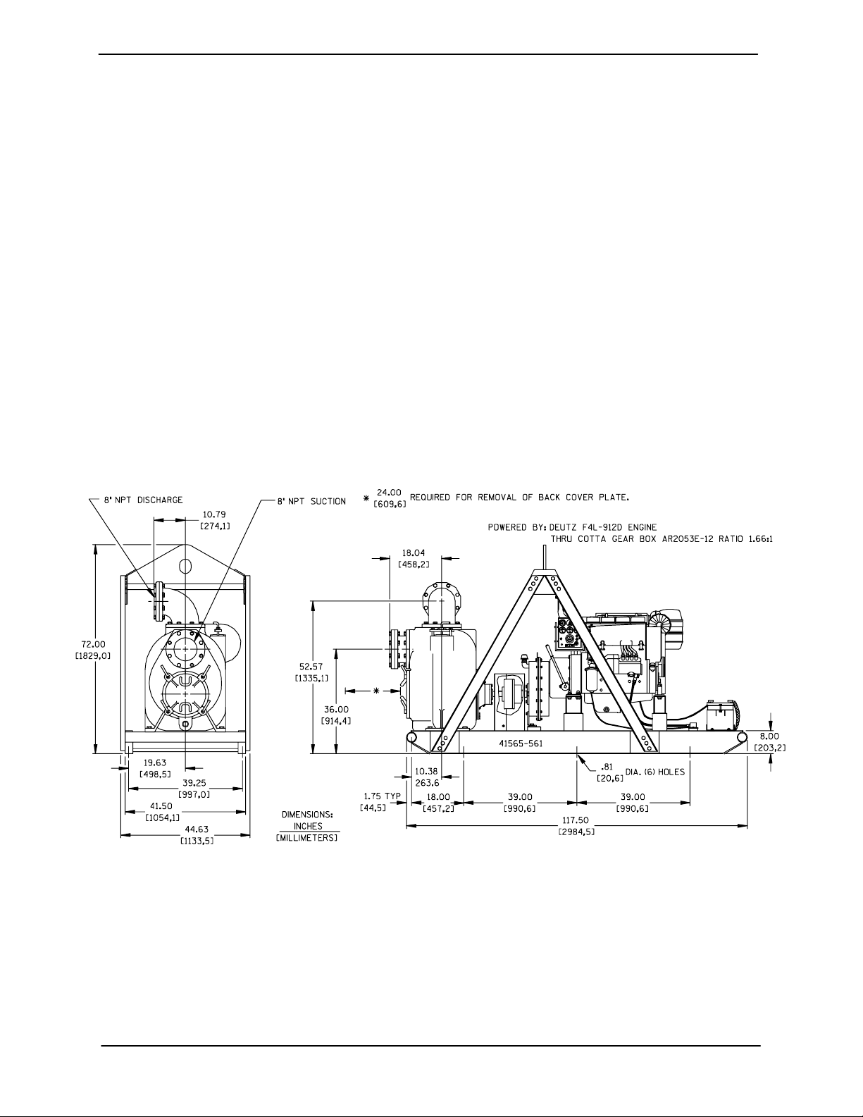
SeeFigure1fortheapproximatephysicaldimensionsofthispump.
Figure 1. Pump Model T8A3--B--F4L
PREINSTALLATION INSPECTION
Thepump assembly wasinspected and tested beforeshipment fromthe factory. Beforeinstallation,
inspect the pump fordamage which may have occurred during shipment. Check a s follows:
a. Inspect thepump assemblyforcracks,dents,
damaged threads, and other obvious damage.
b. Check for and tighten loose attaching hard-
ware. Since gaskets tend to shrink after dry-
PAGE B -- 1INSTALLATION
Page 9
OM--04326 TSERIES
ing, check for loose hardware at mating surfaces.
c. Carefully read all tags, decals, and markings
onthepumpassembly,and performallduties
indicated.
d. Check levels and lubricate as necessary. Re-
fer to LUBRICATION in the MAINTENANCE
AND REPAIR section of this manual and perform duties as instructed.
e. If the pump and engine have been stored for
more than 12 months, some of the components or lubricants may have exceeded their
maximumshelflife.Thesemustbeinspected
or replaced to ensure maximum pump service.
If the maximum shelf life has been exceeded, or if
anything appears to be abnormal, contact your
Gorman-Rupp distributor or the factory to determinethe repairor updating policy. Donotputthe
pump into service until appropriate action has
been taken.
sion. Connect and tighten the positive cable first,
then the negative cable.
POSITIONING PUMP
Use lifting and moving equipment in
good repair and with adequate capacity
topreventinjuriesto personnel or damage to equipment. Suction and discharge hoses and piping must be removed from the pump before lifting.
Lifting
Use lifting equipment with a capacity of at least
20,300 pounds (9208 kg). This pump weighs approximately 4,045 pounds (1835 kg),notincluding the weight of accessories and optional wheel
kit. Customer installedequipment such as suction
and discharge piping must be removed before attempting to lift.
Battery Specifications And Installation
Unlessotherwise specified on the pump order, the
engine battery was not included with the unit. Refer to the following specifications when selecting a
battery.
Table 1. Battery Specifications
Voltage
12 Volts
Cold
Crank
Amps
@0
_ F
960 --- 975
Reserve
Capacity
_ F
@80
(Minutes)
365
Amp/
Rating
175
Hr.
Approx.
Overall
Dims.
(Inches)
20.5L
x
8.75W
x
9.75H
Refer to the informationaccompanying the battery
and/or electrolyte solution foractivation andcharging instructions.
Beforeinstallingthe battery, clean the positiveand
negative cable connectors, and the battery terminals. Secure the battery by tightening the
holddown brackets. The terminals and clamps
maybe coated with petroleum jellyto retard corro-
Thepumpassemblycanbeseriously
damagedif thecablesor chainsused tolift
andmovetheunitareimproperlywrapped
around the pump.
Mounting
Locatethepumpinanaccessibleplaceascloseas
practicalto the liquid being pumped. Levelmounting is essential for proper operation.
The pump may have to be supported or shimmed
to provide for level operation or to eliminate vibration.
If the pump has been mounted on a moveable
base,makecertainthebaseisstationarybysetting
the brake and blockingthe wheels before attempting to operate the pump.
To ensure sufficient lubrication and fuel supply to
the engine, do not position the pump and engine
morethan 15_ off horizontal for continuous operation. The pump and engine may be positionedup
PAGE B -- 2 INSTALLATION
Page 10

TSERIES OM--04326
to 30_ off horizontal for intermittent operation
only;however,theengine manufacturer shouldbe
consulted for continuous operation at angles
greater than 15_.
Clearance
When positioning the pump, allow a minimum
clearance of 24 inches (609,6 mm) in front of the
back coverto permit removal of the coverandeasy
access to the pump interior.
SUCTION AND DISCHARGE PIPING
Pump performance is adversely effected by increased suction lift, discharge elevation, and friction losses. See the performance curve and notes
onPageE-1tobesureyouroverallapplicationallows pump to operate within the safe operation
range.
Materials
linesareused, theyshouldhaveadequatesupport
to secure them when filled with liquid and under
pressure.
Gauges
Most pumps are drilled and tapped for installing
discharge pressure and vacuum suction gauges.
If these gauges are desired for pumps that are not
tapped, drill a nd tap the suction and discharge
lines not less than 18 inches (457,2 mm) from the
suction and discharge ports and install the lines.
Installationcloserto the pump may result in erratic
readings.
SUCTION LINES
To avoidairpockets whichcould affect pumppriming, the suction line must be as short and direct as
possible.Whenoperationinvolvesasuctionlift,the
line must always slope upward to the pump from
the source of the liquid being pumped; if the line
slopes down to the pump at any point along the
suction run, air pockets will be created.
Either pipe or hose maybe used for suction and
discharge lines; however, the materials must be
compatiblewiththeliquidbeingpumped.If hose is
used insuction lines, it must be the rigid-wall, reinforcedtype toprevent collapseunder suction.Using piping couplings in suction lines is not recommended.
Line Configuration
Keep suction and discharge lines as straight as
possible to minimize friction losses. Make minimum use of elbows and fittings, w hich substantiallyincreasefriction loss.Ifelbowsarenecessary,
use the long-radius type to minimize friction loss.
Connections to Pump
Before tightening a connecting flange, align it exactlywith the pump port. Never pulla pipe line into
place by tightening the flange bolts and/ or couplings.
Lines near the pump must be independently supported to avoid strain on the pump which could
cause excessive vibration, decreased bearing life,
and increased shaft and seal wear. If hose-type
Fittings
Suction lines should bethesame sizeas the pump
inlet. If reducers are used in suction lines, they
should be the eccentric type, and should be installedwith the flat part ofthe reducers uppermost
to avoid creating air pockets. Valves are not normally used in suction lines, but if a valve is used,
install it with the stem horizontal to avoid air pockets.
Strainers
If a strainer is furnished with the pump, be certain
touseit; any sphericalsolidswhichpass througha
strainer furnished with the pump will also pass
through the pump itself.
If a strainer is not furnished with the pump, but is
installed by the pump user, make certain that the
total area of the openings in the strainer is at least
three or four times the cross section of the suction
line,and that the openings will not permit passage
of solids larger than the solids handling capability
of the pump.
Thispump is designedtohandle up to 3-inch(76,2
mm) diameter spherical solids.
PAGE B -- 3INSTALLATION
Page 11
OM--04326 TSERIES
Sealing
Since even a slight leak will affect priming, head,
and capacity, especially when operating with a
high suction lift, all connections in the suction line
should be sealed with pipe dope to ensure an airtight seal. Follow the sealant manufacturer’s recommendations when selecting and applying the
pipe dope. The pipe dope should be compatible
with the liquid being pumped.
Suction Lines In Sumps
If a single suction line is installed in a sump, it
should be positioned away from the wall of the
sumpat a distanceequal to 1 1/2 times the diameter of the suction line.
If there is a liquid flow from an open pipe into the
sump, the flow should be kept away from the suctioninlet because the inflowwill carry air down into
the sump, and air entering the suction line w ill reduce pump efficiency.
Ifit is necessary to position inflowclose to the suctioninlet,installa bafflebetween theinflowand the
suctioninlet at a distance 1-1/2times the diameter
of the suction pipe. The baffle will allow entrained
air to escape from the liquid before it is drawn into
the suction inlet.
If two suction lines are installed in a single sump,
theflowpaths mayinteract, reducing theefficiency
of one or both pumps. To avoid this, position the
suction inlets s o that they are separated by a distance equal to at least 3 times the diameter of the
suction pipe.
Suction Line Positioning
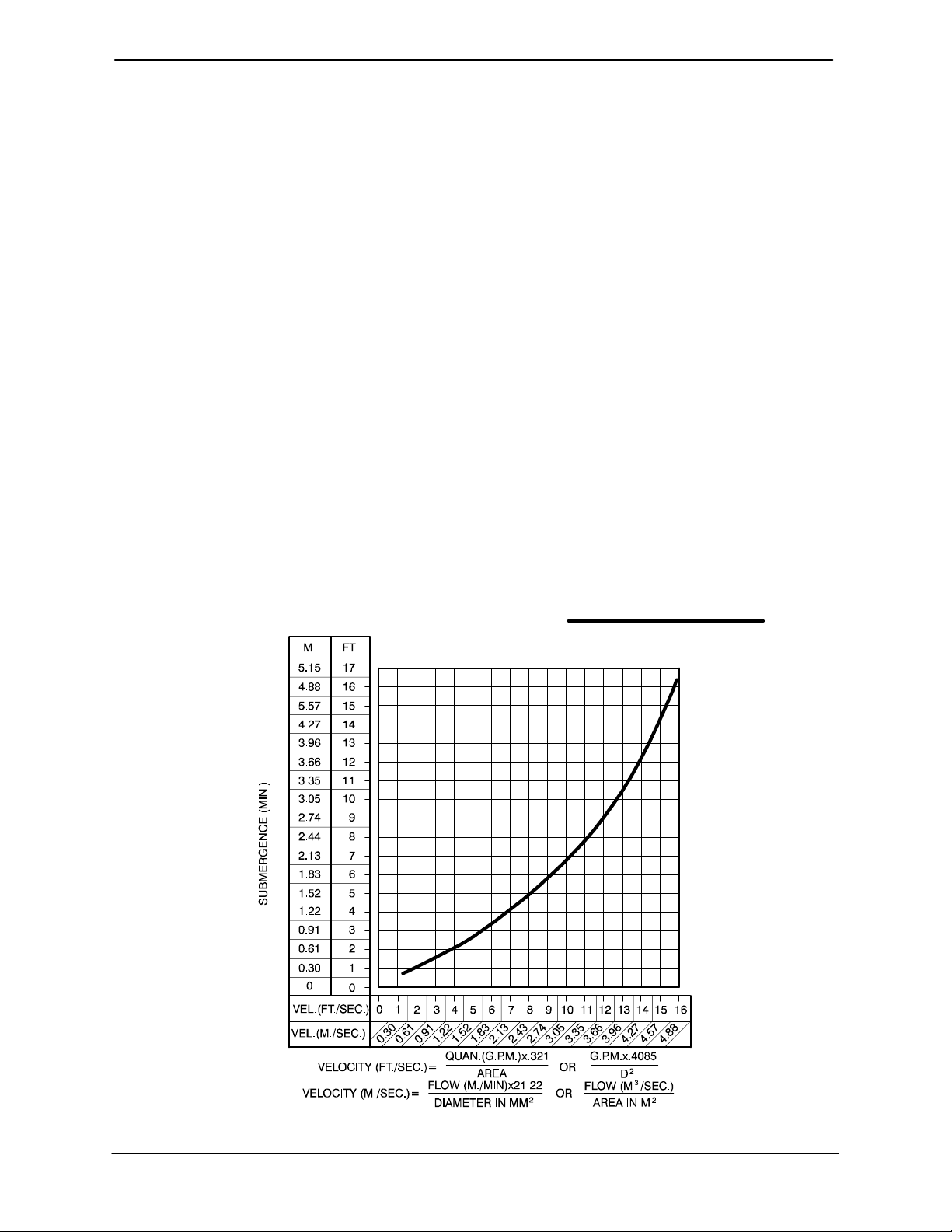
The depth of submergence of the suction line is
critical toefficientpumpoperation. Figure2 shows
recommended minimum submergence vs. veloc-
ity.
NOTE
The pipe submergence required may be reduced
by installinga standardpipe increaser fitting at the
endof thesuction line. The largeropening size will
reduce the inlet velocity. Calculate the required
submergence using the following formula based
on the increased opening size (area or diameter).
Figure 2. Recommended Minimum Suction Line Submergence vs. Velocity
PAGE B -- 4 INSTALLATION
Page 12
TSERIES OM--04326
DISCHARGE LINES
Siphoning
Donot terminate the discharge lineat a level lower
than that of the liquid being pumped unless a siphon breaker is used in the line. Otherwise, a siphoning action causing damage to the pump
could result.
Valves
A check valvein the discharge lineis normally recommended, but it is not necessary in low discharge head applications.
If a throttling valve is desired in the discharge line,
useavalveaslargeasthelargestpipetominimize
friction losses. Never install a throttling valve in a
suction line.
Withhighdischargeheads,itisrecommendedthat
a throttling valve and a system check valve be in stalled in the discharge line to protect the pump
from excessive shock pressure and reverse rotation when it is stopped.
affect pump discharge capacity; however, the bypass line should be at least 1 inch (25,4 mm) in diameter to minimize the chance of plugging.
Inlow dischargeheadapplications(lessthan 30
feet (9,1 m)), it is recommended that the bypass
line be run back to the wet well, and located 6
inches below the water level or cut-off point of the
low level pump. In some installations, this bypass
outline may be terminated with a six-to-eight foot
(1,8 to 2,4 m) length of 1-1/4 inch (31,8 mm) I.D.
smooth-bore hose; air and liquid vented during
the priming process willthen agitate the hose and
break up any solids, grease, or other substances
likely to cause clogging.
Abypasslinethatisreturnedtoawetwell
must be securedagainstbeing drawninto
the pump suction inlet.
It is also recommended that pipe unions be installed at each 90_ elbow in a bypass line to ease
disassembly and maintenance.
If the application involves a high discharge
head, gradually close the discharge
throttling valve before stopping the pump.
Bypass Lines
Self-primingpumps are not air compressors. Duringthepriming cycle, air fromthesuction line must
be vented to atmosphere on the discharge side. If
the discharge line is open, this air will be vented
through the discharge. However, if a check valve
has been installed in the discharge line, the dischargesideofthepumpmustbeopenedtoatmosphericpressurethrough abypass line installedbetween the pump discharge and the check valve. A
self-priming centrifugal pump will not prime if
there is sufficientstatic liquidhead to hold the discharge check valve closed.
NOTE
Thebypass line should be sized so that it does not
In high discharge head applications (more than
30 feet (9,1 m), an excessive amount of liquid may
bebypassedandforced back tothewet wellunder
the full working pressure of the pump; this will reduce overall pumping efficiency. Therefore, it is
recommended that a Gorman-Rupp Automatic
AirReleaseValvebeinstalledin thebypassline.
Gorman-Rupp Automatic Air Release Valves are
reliable, and require minimum maintenance. See
Automatic Air Release Valves in this section for
installation and theory of operation of the Automatic Air Release Valve. Consult your GormanRupp distributor, or contact the Gorman-Rupp
CompanyforselectionofanAutomaticAirRelease
Valve to fit your application.
Except in certain specific applications (to
prevent flooding during service of an automatic air release valve in a below-ground
lift station), if a manual shut-off valve is installed anywhere in a bypass line, it must
PAGE B -- 5INSTALLATION
Page 13
OM--04326 TSERIES
be a full-opening, ball-type valve to prevent plugging by solids.
A manual shut-off valve should not be
installed in any bypass line. A manual
shut-off valve may inadvertently be left
closed during operation. A pump which
has lost prime may continue to operate
without reaching prime, causing dangerousoverheating and possibleexplo-
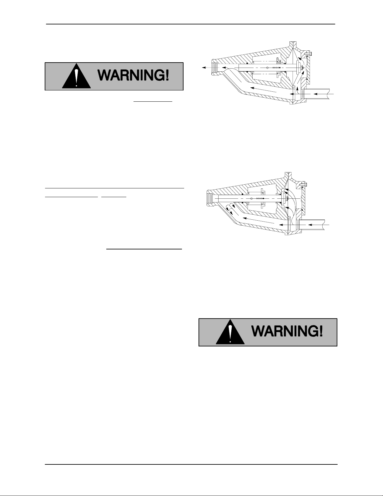
Duringthepriming cycle, airfromthe pump casing
flowsthroughthebypassline,andpassesthrough
theAirReleaseValvetothewetwell(Figure3).
Figure3.ValveinOpenPosition
sive rupture of the pump casing. Personnel could be severely injured.
Allow an over-heated pump to cool before servicing. Do not remove plates,
covers,gauges,orfittingsfroman overheated pump. Liquid within the pump
canreach boiling temperatures,and vaporpressure withinthe pump can cause
parts being disengaged to be ejected
with great force. After the pump cools,
drain the liquid from the pump by removing the casing drain plug. Use caution when removing the plug to prevent
injury to personnel from hot liquid.
AUTOMATIC AIR RELEASE VALVE
When the pump is fullyprimed, pressure resulting
from flow against the valve diaphragm compresses the spring and closesthe valve(Figure 4).
The valve will remain closed, reducing the bypass
ofliquidto1 to 5gallonsper minute, untilthepump
loses its prime or stops.
Figure 4. Valve in Closed Position
When properly installed and correctly adjusted to
the specific hydraulic operating conditions of the
application, the Gorman-Rupp Automatic Air ReleaseValvewillpermitairtoescapethroughthebypass line, and then close automatically when the
pump is fully primed and pumping at full capacity.
Someleakage (1to 5 gallons(3,8to18,9
Liters) per minute) will occur when the
valveisfullyclosed.Besurethebypass
line is directed back to the wet well or
tank to prevent hazardous spills.
Whenthe pump shutsdown, the springreturnsthe
diaphragm t o its original position. Any solids that
Theory of Operation
Figures 3 and 4 show a cross-sectional view of the
AutomaticAir Release Valve, and a corresponding
description of operation.
PAGE B -- 6 INSTALLATION
mayhaveaccumulated inthe diaphragmchamber
settle to the bottomand are flushed out during the
next priming cycle.
NOTE
The valve will remain open if the pump does not
Page 14
TSERIES OM--04326
reach its designed capacity or head. Valve closing
pressureis dependentuponthedischargeheadof
the pump at full capacity . The range of the valve
closing pressure is established by the tensionrate
ofthespring asordered fromthefactory.Valveclosing pressure can be further adjusted to the exact
system requirements by moving the spring retaining pin up or down the plunger rod to increase or
decrease tension on the spring. Contact your Gorman-Rupp distributor or the Gorman-Rupp Company for information about an Automatic Air Release Valve for your specific application.
CLEAN-OUT
COVER
INSTALL AIR RELEASE VALVE
IN HORIZONTAL POSITION
90_ LONG
RADIUS
ELBOW
SUPPORT
BRACKET
Air Release Valve Installation
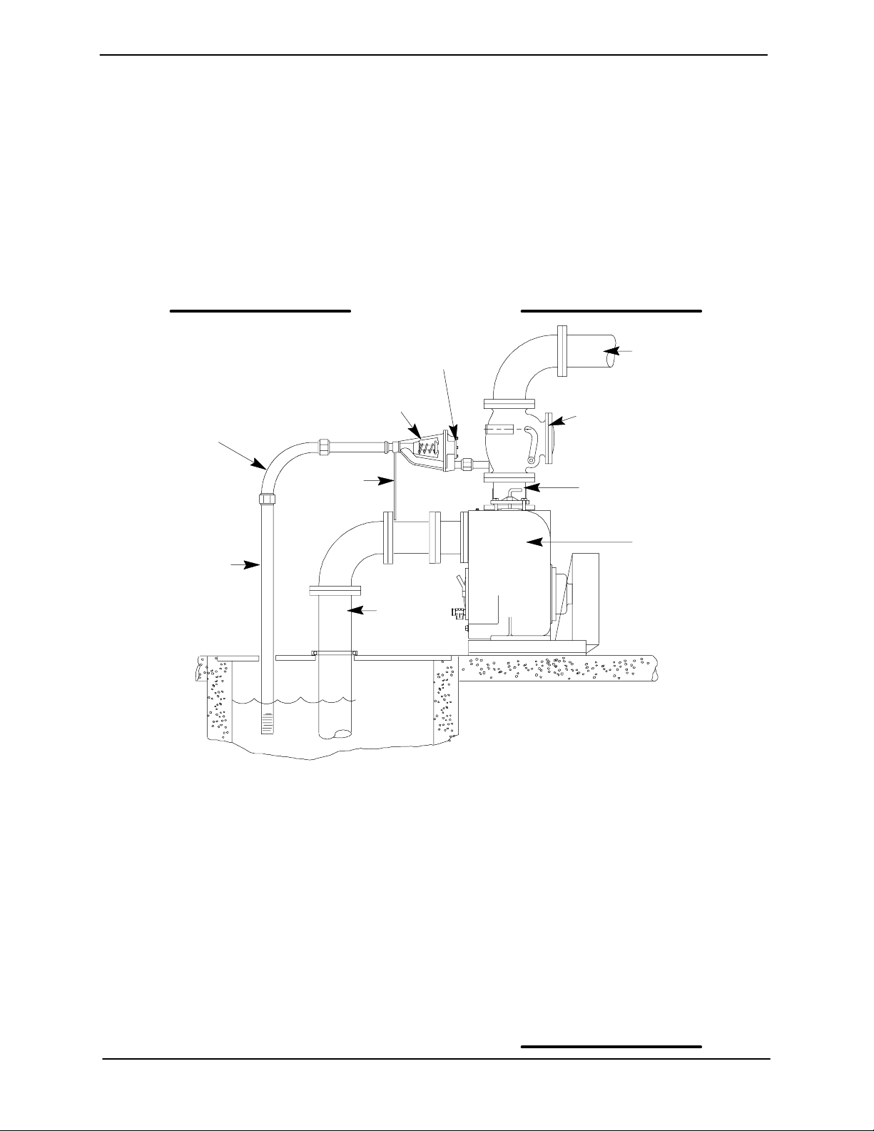
The Automatic Air Release Valve must be independently mounted in a horizontal position and
connected to the discharge line of th e self-priming
centrifugal pump (see Figure 5).
NOTE
IftheAir ReleaseValveistobe installedonastaged
pump application, contact the factory for specific
installationinstructions.
DISCHARGE PIPE
DISCHARGE
CHECK VALVE
PUMP DISCHARGE
BLEED LINE 1”
(25,4 MM) DIA. MIN.
(CUSTOMER
FURNISHED)
EXTEND 6”
(152,4 MM)
BELOW LIQUID
LEVEL SURFACE
SUCTION
LINE
WET WELL
OR SUMP
Figure 5. Typical Automatic Air Release Valve Installation
The valve inlet line must be installed between the
pumpdischargeportandthenon-pressurizedside
of the discharge check valve. The valve inlet is at
thelargeendofthevalvebody,andisprovided
with standard 1 inch NPT pipe threads.
The valve outlet is located at the opposite end of
the valve, and is also equipped with standard 1
inch NPT pipe threads. The outlet should be connectedtoa bleedlinewhich slopes backto thewet
well or sump. The bleed linemust bethesame size
asthe inlet piping,orlarger.Ifpipingisusedforthe
SELF-PRIMING
CENTRIFUGAL
PUMP
bleed line, avoid the use of elbows whenever possible.
NOTE
It is recommended that each Air Release Valve be
fitted with an independent bleeder line directed
back to the wet well. However, if multiple Air Release Valves are installed in a system, the bleeder
lines may be directedto a common manifold pipe.
Contact your Gorman-Rupp distributor or the Gorman-RuppCompany for information aboutinstallation of an Automatic Air Release Valvefor your specific application.
PAGE B -- 7INSTALLATION
Page 15
OM--04326 TSERIES
ALIGNMENT
Thealignment ofthe pumpand itspower sourceis
critical for trouble-free mechanical operation. The
driver and pump must be mounted so that their
shafts are aligned with and parallel to each other.
Whenmountedat the Gorman-Ruppfactory,driver
andpumparealignedbeforeshipment.Misalignment can occur in transit and handling. Pumps
shouldbechecked,andrealignedifnecessary,before being put into operation. Before checking
alignment, tighten the hardware securing the
pump to the base.
Theaxisofthedriveunitmustbealignedtothe axis
ofthepumpshaftinboththehorizontalandvertical
planes. Most couplings require a specific gap or
clearance between the driving and the driven
shafts. Refer to the coupling manufacturer’s service literature for information.
This pump is furnished with a flexible coupling. To
check alignment, use a feeler gauge or a taper
gauge between the coupling halves every 90 degrees. The coupling is in alignmentwhen the hubs
are the same distance apart at all points.
To check parallel adjustment, lay a straightedge
across both coupling halves at the top, bottom,
and side. The coupling is in horizontal parallel
alignment when the straightedge rests evenly on
bothhalvesofthe coupling.Usea feelergaugebetween the coupling and the straightedge to measure the amount of misalignment.
Coupling and alignment adjustments may be
made by loosening the hold-down bolts and shifting the driver and/or pump, or by shimming as required.
Adjusting the alignment in one direction
may alter the alignment in another direction. Check each procedure after altering
alignment.
Do not operate the pump without the
coupling guard in place over the rotating parts. Exposed rotating parts can
catchclothing,fingers,ortools,causing
severe injury to personnel.
PAGE B -- 8 INSTALLATION
Page 16
TSERIES
OM--04326
OPERATION --- SECTION C
Review all SAFETY information in Section A.
Follow the instructions on all tags, labels and
decals attached to the pump.
This pump is designed to handle dirty
water containing specified entrained
solids.Donotattempttopumpvolatile,
corrosive, or flammable liquids which
maydamagethepumpor endanger personnel as a result of pump failure.
Never tamper with the governor to gain
more power. The governor establishes
safe operating limits that should not be
exceeded. The maximum continuous
operating speed for this pump is 2200
RPM.
Add liquid to the pump casing when:
1. The pump is being put into service for the
first time.
2. The pumphas notbeenusedfor a considerable length of time.
3. The liquid in the pump casing has evaporated.
Once the pump casing has been filled, the pump
will prime and reprime as necessary.
After filling the pump casing, reinstall
and tighten the fill plug. Do not attempt
to operate the pump unless allconnecting piping i s securely installed. Otherwise, liquid in the pump forced out under pressure could cause injury to personnel.
To fill the pump, remove the pump casing fillcover
or fill plug in the top of the casing, and add clean
liquid until the casing is filled. Replace the fill cover
or fill plug before operating the pump.
PRIMING
STARTING
Install the pump and piping as described in IN STALLATION. Make sure that t he piping connec-
tions are tight, and that the pump is securely
mounted. Check that the pump is properly lubricated (see LUBRICATION in MAINTENANCE
AND REPAIR).
This pump is self-priming, but the pump should
never be operated unless there is liquid in the
pump casing.
Consult the operations manual furnished with the
engine.
OPERATION
A Gorman-Rupp automatic air release valve may
beinstalledinabypassline,or the bypass linemay
be left open.
A manual shut-off valve should not be
Never operate this pump unless there is
liquid in the pump casing. The pump will
notprimewhendry.Extended operationof
a dry pump will destroy the seal assembly.
OPERATION PAGE C -- 1
installed in any bypass line. A manual
shut-off valve may inadvertently be left
closed during operation. A pump which
has lost prime may continue to operate
Page 17
OM--04326 TSERIES
without reaching prime, causing dangerousoverheating and possibleexplosive rupture of the pump casing. Personnel could be severely injured.
Lines With A Bypass
Ifa Gorman-Rupp Automatic Air ReleaseValvehas
been installed, the valve will automatically open to
allow the pump to prime, and automatically close
after priming is complete (see INSTALLATION for
Air Release Valve operation).
If the bypass line is open, air from the suction line
willbe dischargedthrough the bypass line back to
the wet well during the priming cycle. Liquid will
then continue to circulate through the bypass line
while the pump is in operation.
Lines Without A Bypass
Open all valves in the discharge line and start the
engine. Priming is indicated by a positive reading
on the discharge pressure gauge or by a quieter
operation. The pump may not prime immediately
because the suction line must first fill with liquid. If
the pump fails to prime within five minutes, stop it
and check the suction line for leaks.
Afterthepumphas been primed,partiallyclosethe
discharge line throttling valve in order to fill the line
slowly and guard against excessive shock pressure which could damage pipe ends, gaskets,
sprinkler heads, and any other fixtures connected
to the line. When the discharge line is completely
filled,adjustthethrottlingvalve to the required flow
rate.
Leakage
No leakage should be visible at pump mating surfaces, or at pump connections or fittings. Keep all
lineconnectionsandfittingstight to maintainmaximum pump efficiency.
Liquid Temperature And Overheating
The maximum liquid temperature for this pump is
160_ F(71_ C).Donotapplyitatahigheroperat-
ing temperature.
Overheating can occur if operated with the valves
in the suction or discharge lines closed. Operating
against closed valves could bring the liquid to a
boil, build pressure, and cause the pump to rupture or explode. If overheating occurs, stop the
pumpand allow ittocompletelycoolbefore servicing it. Refill the pump casing with cool liquid.
Do not remove plates, covers, gauges,
pipe plugs, or fittings from an overheated pump. Vaporpressure within the
pump can cause parts being disengagedto be ejected withgreatforce.Allowthe pump to completely coolbefore
servicing.
Asa s afeguard against ruptureor explosiondueto
heat, this pump is equipped with a pressure relief
valve which will open if vapor pressure within the
pump casing reaches a critical point. If over-heatingdoesoccur ,stop the pump immediately and allow it to cool before servicing it. Approach any
over-heated pump cautiously.Itisrecommended that the pressure reliefvalve assembly be
replaced at each overhaul, or any time the pump
casing over-heats and activates the valve. Never
replace this valve with a substitute which has not
been specified or provided by the Gorman-Rupp
Company.
Strainer Check
If a suction strainer has been shipped with the
pump or installed by the user, check the strainer
regularly, and clean it as necessary. The strainer
shouldalsobechecked ifpumpflowrate beginsto
drop. If a vacuum suction gauge has been installed, monitor and record the readings regularly
to detect strainer blockage.
Never introduce air or steam pressure into the
pump casing or pipingto remove a blockage. This
could result in personal injury or damage to the
equipment. If backflushing is absolutely necessary,liquidpressuremust be limitedto50% of the
maximum permissible operating pressure shown
on the pump performance curve.
OPERATIONPAGE C -- 2
Page 18
TSERIES
OM--04326
Pump Vacuum Check
Withthe pumpinoperative,installavacuumgauge
in the system, using pipe dope on the threads.
Block the suction line and start the pump. At operating speed the pump should pull a vacuum of 20
inches (508 mm) or more of mercury. If it does not,
check for airleaks inthe seal, gasket, or discharge
valve.
Openthesuction line, andread the vacuumgauge
with the pump primed and at operation speed.
Shut off the pump. Thevacuum gauge reading will
immediately drop proportionate to static suction
lift,andshouldthenstabilize.Ifthevacuumreading
falls off rapidly after stabilization, an air leak exists.
Before checking for the source of the leak, check
the point of installation of the vacuum gauge.
STOPPING
Never halt the flow of liquid suddenly. If the liquid
being pumped is stopped abruptly, damaging
shock waves can be transmitted to the pump and
piping system. Close all connecting valves slowly.
On engine driven pumps, reduce the throttle
speed slowlyandallow theengineto idlebrieflybefore stopping.
If the application involves a high discharge
head, gradually close the discharge
throttling valve before stopping the pump.
Afterstoppingthepump, switchofftheengineignition and disconnect the positive battery cable to
ensure that the pump will remain inoperative.
Cold Weather Preservation
In below freezing conditions, drain the pump to
preventdamage from freezing. Also,cleanoutany
solids by flushing with a hose. Operate the pump
for approximatelyone minute; this will remove any
remaining liquid that could freeze the pump rotating parts. If the pump will be idle for more t han a
few hours, or if it has been pumping liquids containing a large amount of solids, drain the pump,
and flush it thoroughly with clean water.Toprevent
large solids from clogging the drain port and preventing the pump from completely draining, insert
a rod or stiff wire in the drain port, and agitate the
liquid during the draining process. Clean out any
remaining solids by flushing with a hose.
BEARING TEMPERATURE CHECK
Bearingsnormally run at higher than ambient temperatures because of heat generated by friction.
Temperatures up to 160_F(71_C) are considered
normalforbearings, and they canoperatesafelyto
at least 180_F(82_C).
Checkingbearingtemperaturesbyhand is inaccurate. Bearing temperatures can be measured accurately by placing a contact-type thermometer
against the housing. Record this temperature for
future reference.
A sudden increase in bearing temperatures is a
warning that the bearings are at the point of failing
to operate properly. Make certain that the bearing
lubricant is of the proper viscosity and at the correct level (see LUBRICATION in Section E). Bear-
ing overheating can also be caused by shaft
misalignment and/or excessive vibration.
When pumps are first started, the bearings may
seem to run at temperatures above normal. Continued operation should bring the temperatures
down to normal levels.
OPERATION PAGE C -- 3
Page 19
TROUBLESHOOTING --- SECTION D
Review all SAFETY information in Section A.
Beforeattemptingtoopen orservice the
pump:
1. Familiarize yourselfwith thismanual.
2. Switch off engine ignition and disconnectthe positive batterycable to
ensure that the pump will remain inoperative.
3. Allow the pump to completely cool if
overheated.
4. Check the temperature before open ing any covers, plates, or plugs.
5. Close the suction and discharge
valves.
6. Ventthe pump slowlyand cautiously.
7. Drain the pump.
OM--04326TSERIES
Table 1. Trouble Shooting Chart
TROUBLE POSSIBLE CAUSE PROBABLE REMEDY
PUMP FAILS TO PRIME Not enough liquid in casing.
Suctioncheck valve contaminated or
damaged.
Air leak in suction line.
Lining of suction hose collapsed.
Leakingorwornsealorpumpgas-
ket.
Suction lift or discharge head too
high.
Strainer clogged.
PUMP STOPS OR FAILS
TO DELIVER RATED
FLOW OR PRESSURE
Air leak in suction line.
Lining of suction hose collapsed.
Addliquidtocasing.SeePRIMING.
Clean or replace check valve.
Correct leak.
Replace suction hose.
Check pump vacuum. Replace leak-
ingorwornsealorgasket.
Check piping installation and install
bypass line if needed. See INSTAL-
LATION.
Check strainer and clean if necessary.
Correct leak.
Replace suction hose.
TROUBLESHOOTING PAGE D -- 1
Page 20
OM--04326 TSERIES
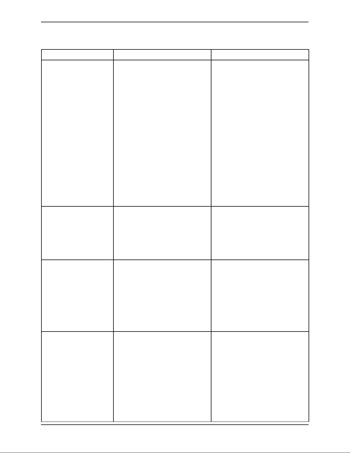
Table 1. Trouble Shooting Chart (cont.)
TROUBLE POSSIBLE CAUSE PROBABLE REMEDY
PUMP STOPS OR FAILS
TO DELIVER RATED
FLOW OR PRESSURE
(cont.)
Leakingorwornsealorpumpgasket.
Strainer clogged.
Check pump vacuum. Replace
leakingorwornsealorgasket.
Check strainer and clean if necessary.
PUMP REQUIRES TOO
MUCH POWER
PUMP CLOGS
FREQUENTLY
Suction intake not submerged at
proper level or sump too small.
Impellerorotherwearingparts
worn or damaged.
Impeller clogged.
Discharge head too high.
Suction lift too high.
Pump speed too slow.
Pump speed too high.
Discharge head too low.
Liquid solution too thick.
Bearing(s) frozen.
Discharge flow too slow.
Check installation and correct submergence as needed.
Replace worn or damaged parts.
Check that impeller is properly centered and rotates freely.
Free impeller of debris.
Install bypass line.
Measure lift w/vacuum gauge. Re-
duce lift and/or friction losses in
suction line.
Check engine output; consult engine operation manual.
Check engine output.
Adjust discharge valve.
Dilute if possible.
Disassemble pump and check
bearing(s).
Open discharge valve fully to in-
crease flow rate, and run engine at
maximum governed speed.
Suction check valve or foot valve
clogged or binding.
Liquid solution too thick.
Dischargelinecloggedorre-
stricted; hose kinked.
EXCESSIVE NOISE Cavitation in pump.
Pumping entrained air.
Pump or drive not securely
mounted.
Impeller clogged or damaged.
Clean valve.
Dilute if possible.
Check discharge lines; straighten
hose.
Reduce suction lift and/or friction
losses in suction line. Record vacuum and pressure gauge readings
and consult local representative or
factory.
Locate and eliminate source of air
bubble.
Secure mounting hardware.
Clean out debris; replace damaged
parts.
TROUBLESHOOTINGPAGE D -- 2
Page 21
TROUBLE POSSIBLE CAUSE PROBABLE REMEDY
BEARINGS RUN TOO
HOT
Table 1. Trouble Shooting Chart (cont.)
Bearing temperature is high, but
within limits.
Check bearing temperature regularly to monitor any increase.
OM--04326TSERIES
Low or incorrect lubricant.
Suction and discharge lines not
properly supported.
Drive misaligned.
Check for proper type and level of
lubricant.
Check piping installation for proper
support.
Align drive properly.
TROUBLESHOOTING PAGE D -- 3
Page 22
TSERIES OM--04326
PUMP MAINTENANCE AND REPA IR - SECTION E
MAINTENANCE AND REPAIR OF THE WEARING PARTS OF THE PUMP WILL MAINTAIN PEAK
OPERATING PERFORMANCE.
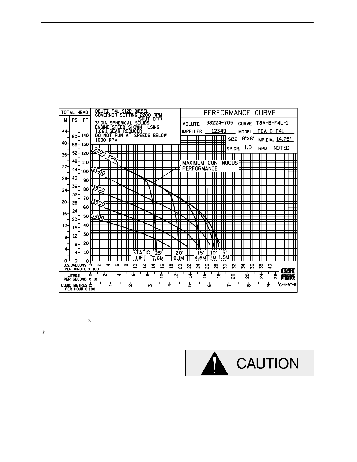
STANDARD PERFORMANCE FOR PUMP MODEL T8A3--B--F4L
Based on 70_ F(21_ C) clear water at sea level
with minimum suctionlift. Sincepump installations
areseldomidentical,yourperformancemaybedifferent due to such factors as viscosity, specific
gravity, elevation, temperature, and impeller trim.
Contact the Gorman-Rupp Company to verify performance or part numbers.
Pump speed and operating condition
If your pump serial number is followed by an “N”,
your pump is NOT astandardproductionmodel.
MAINTENANCE & REPAIR PAGE E -- 1
points must be within the continuous performance range shown on the curve.
Page 23
SECTION DRAWING
TSERIESOM--04326
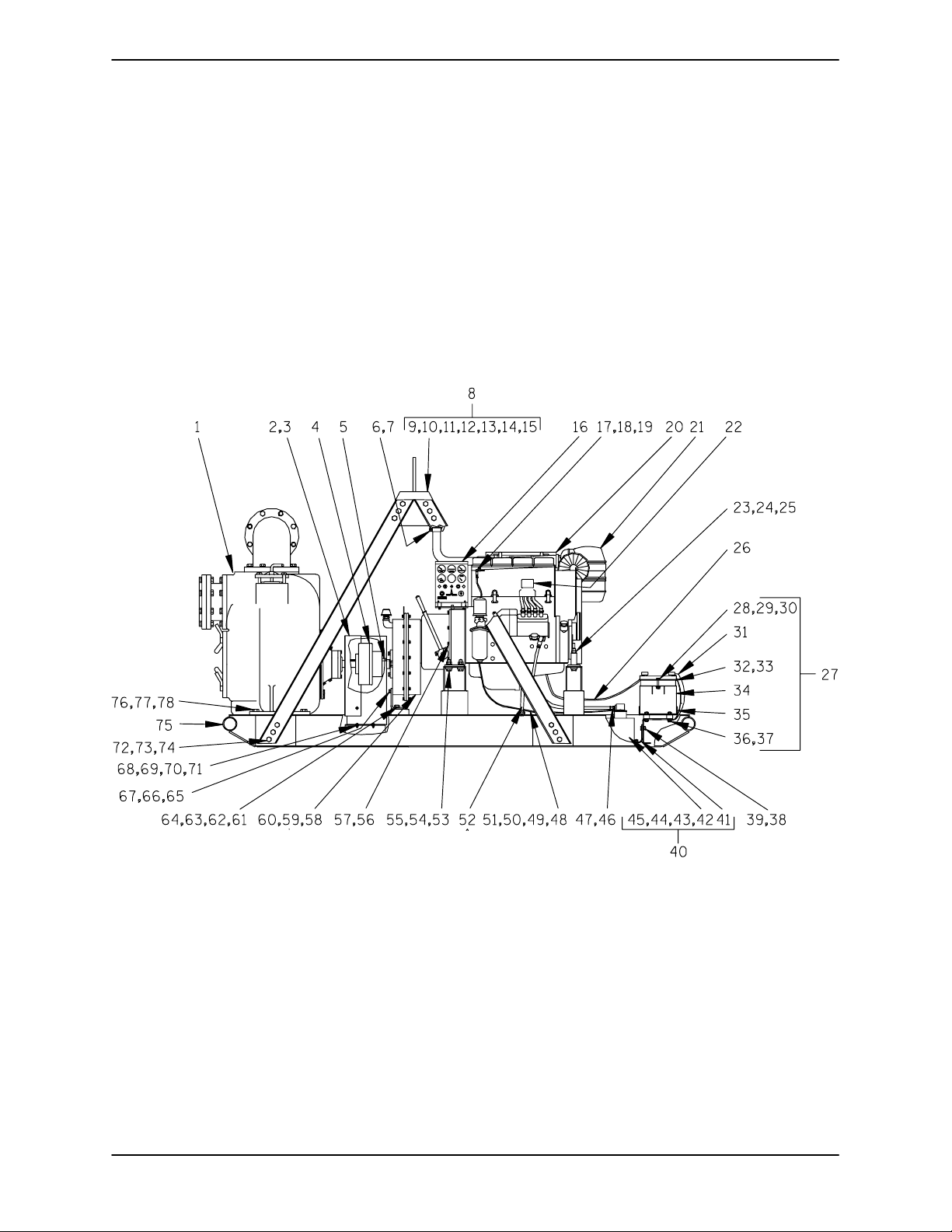
Fi g ure 1 . Pu mp Mo del T 8A3 --- B --- F4L
MAINTENANCE & REPAIRPAGE E -- 2
Page 24
TSERIES OM--04326
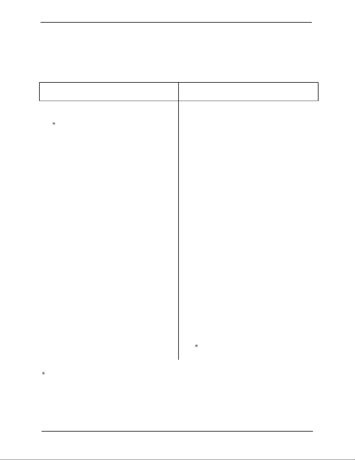
PARTS LIST
Pu mp Mo del T 8A 3 --- B --- F 4 L
(From S/N 1131762 up)
Ifyour pump serialnumber is followedbyan “N”,your pumpis NOT a standard production model. Contact
the Gorman-Rupp Company to verify part numbers.
ITEM
PART NAME PART
NO.
NUMBER
MAT’L
CODE
QTY ITEM
NO.
PART NAME PART
NUMBER
MAT’L
CODE
QTY
1 PUMP EN D ASSY T8 A3 --- B --- (F4 L) 1
2 COUPLING GUARD ASSY 42342---210 --- --- --- 1
3 GRD WARNING DECAL 38816---062 --------- 1
4
1-3/4 X 2-1/4 COUPLING 44165---007 -- ---- --- 1
5 KEY N1016 15990 1
6 EXHAUST ELBOW 31912---023 15990 1
7 WEATHER CAP S1331 --------- 1
8 HOISTING BAIL 44715---003 --- --- --- 1
9 ---SIDE MEMBER 34721---028 15990 2
10 ---SIDE MEMBER 34721---029 15990 2
11 ---SPACER PLATE 33271-- -013 15020 4
12 ---HEX HD CAPSCREW B1208 15991 12
13 ---LOCKWASHER J12 15991 12
14 ---HEX NUT D12 15991 12
15 ---TOP SECT HO BAIL 44718-- -014 24150 1
16 CONTROL PANEL 29277---012 --- --- --- 1
17 FUEL LINE 11308F ----- ---- 1
18 HOSE CLAMP 26518-- -641 --------- 1
19 HOSE BARB FITTING 26523---443 --------- 1
20 MUFFLER GUARD ASSY 42331---031 --- --- --- 1
21 DEUTZ F4L ENGINE 29217---043 --------- 1
22 CAUTION DECAL 38816---169 --- --- --- 1
23 HEX HD CAPSCREW B1017 15991 2
24 LOCKWASHER J10 15991 2
25 HEX NUT D10 15991 2
26 54” CABLE ASSY 47311- --116 --- --- --- 1
27 BAT TER Y B OX ASS Y GR P40 --- 08 C --- --- --- 1
28 ---HEX HD CAPSCREW B0607 15991 2
29 ---FLAT WASHER K06 15991 2
30 ---FLANGED HEX NUT 21765---314 --- --- --- 2
31 ---GROUND CABLE ASSY 47311---064 --- --- --- 1
32 ---BATTERY BOX LID ASSY 42113---012 24150 1
33 ---12V BATTERY SEE OPTIONS
34 ---BATTERY TAG 38818-- -506 --------- 1
35 ---BATTERY BOX ASSY 42431---030 24150 1
36 ---STUD MOUNT 24631-- -006 --------- 4
37 ---FLANGED HEX NUT 21765---314 --- --- --- 8
38 FLANGED HEX NUT 21765---314 --------- 10
39 HEX HD CAPSCREW B0604 15991 10
40 FUEL TANK/GRD ASSY 46711- --041 --- --- - -- 1
41 ---FUEL TANK GUARD 34851---178 15080 1
42 ---FUEL TANK ASSY 46711---042 24150 1
43 ---FLANGED HEX NUT 21765---314 --- --- --- 6
44 ---CARRIAGE BOLT AB0604 15991 6
45 ---FLAT WASHER K06 15991 6
46 HOSE ASSY 46341-- -800 --------- 1
47 MALE CONNECTOR S1447 --- --- --- 1
48 REDUCING ELBOW Q0402 11999 1
49 FUEL RETURN ASSY 14294 24030 1
50 HOSE CLAMP 26518-- -641 --------- 1
51 MALE CONNECTOR 26523---382 --- --- --- 1
52 OIL DRAIN ASSY 46342---007 --------- 1
53 HEX HD CAPSCREW B1007 15991 4
54 LOCKWASHER J10 15991 4
55 HEX NUT D10 15991 4
56 HEX HD CAPSCREW 22645---164 ------ --- 12
57 LOCKWASHER 21171-- -511 --------- 12
58 SPEED REDUCER 24572---204 --------- 1
59 HEX HD CAPSCREW 22645---166 ------ --- 8
60 LOCKWASHER 21171-- -511 --------- 8
61 HEX HD CAPSCREW B0810 15991 2
62 LOCKWASHER J08 15991 2
63 HEX NUT D08 15991 2
64 FLAT WASHER K08 15991 2
65 SUPPORT 34264-- -047 15080 1
66 HEX HD CAPSCREW B0805 15991 4
67 LOCKWASHER J08 15991 4
68 HEX HD CAPSCREW B0405 15991 4
69 FLAT WASHER K04 15991 4
70 LOCKWASHER J04 15991 4
71 HEX NUT D04 15991 4
72 HEX HD CAPSCREW B1206 15991 12
73 LOCKWASHER J12 15991 12
74 HEX NUT D12 15991 12
75 COMBINATION BASE 41565---561 24150 1
76 HEX HD CAPSCREW B1209 15991 4
77 LOCKWASHER J12 15991 4
78 HEX NUT D12 15991 4
NOT SHOWN:
WARNING DECAL 2613FE --- --- --- 1
OPTIONAL:
12V BATTERY 29331-- -506 --------- 1
4-W HEE L AUTO ST EER GRP 30 --- 10 D --- --- --- 1
REP MUFFLER GRD ASSY 42331---048 ----- ---- 1
INDICATES PARTS RECOMMENDED FOR STOCK
Above SerialNumbersDo Not Apply To Pumps Made In Canada.
CANADIAN SERIAL NO. ................................................. AND UP
MAINTENANCE & REPAIR PAGE E -- 3
Page 25
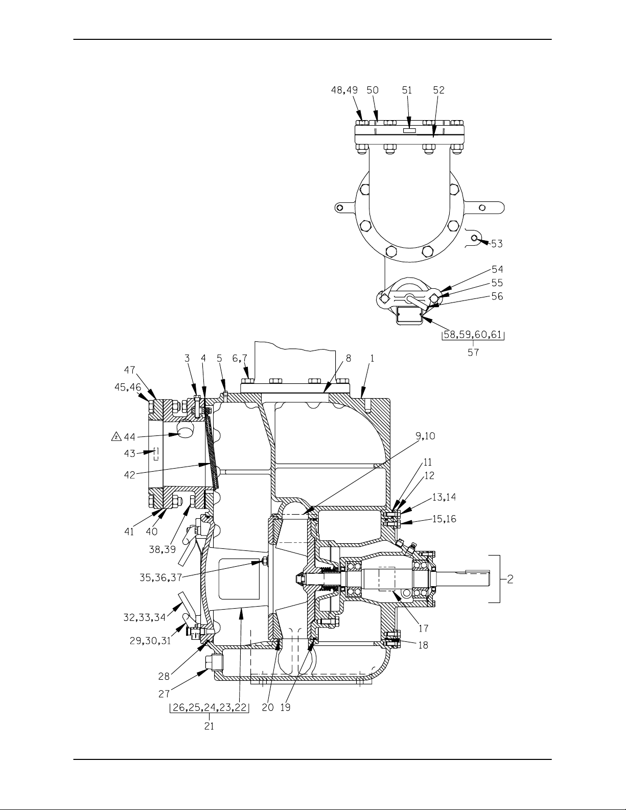
SECTION DRAWING
TSERIESOM--04326
Fi g ure 2 . T8 A3 --- B --- ( F4 L ) Pu mp En d As se m b ly
MAINTENANCE & REPAIRPAGE E -- 4
Page 26
TSERIES OM--04326
PARTS LIST
T8 A3 --- B --- (F4 L) P ump E n d Asse m bly
ITEM
PART NAME PART
NO.
NUMBER
MAT’L
CODE
QTY ITEM
NO.
PART NAME PART
NUMBER
MAT’L
CODE
QTY
1 PUMP CASING 38224---705 10010 1
2 REPAIR ROTATING ASSY 44163---119 --------- 1
3 CHECK VALVE PIN 12357 17010 1
4
SUCTION FLANGE GSKT 12356G 19370 1
5 PIPE PLUG P04 15079 1
6 HEX HD CAPSCREW B1209 15991 8
7 LOCKWASHER J12 15991 8
8
DISCH FLANGE GSKT 25113---038 --------- 2
9 NAME PLATE 38818-- -025 13990 1
10 DRIVE SCREW BM#04---03 17000 4
11
ROT ASSY SHIM SET 48261---030 --- --- --- 6
12 CASING RING 31281---016 15990 1
13 HEX HD CAPSCREW B0806 15991 6
14 LOCKWASHER J08 15991 6
15 HEX HD CAPSCREW B0805 15991 6
16 LOCKWASHER J08 15991 6
17 ROTATION DECAL 2613M --------- 1
18
INTERMEDIATE O-RING S1914 --------- 1
19
SEAL PLATE O-RING S1914 --------- 1
20
WEAR PLATE ASSY 12348A 10010 1
21 BACK COVER ASSY 42111---954 ------ --- 1
22 ---COVER PLATE NOT AVAILABLE 1
23 ---WARNING PLATE 2613EV 13990 1
24 ---DRIVE SCREW BM#04---03 17000 4
25
---PRESS RELIEF VALVE 26662---005 --------- 1
26 ---WARNING DECAL 38816---302 -- ---- --- 1
27 CASING DRAIN PLUG P32 10009 1
28
BACK COVER O-RING S1915 ---- ----- 1
29 COVER PLATE HANDLE 12354 13010 2
30 HEX HD CAPSCREW B0604 15991 4
31 LOCKWASHER J06 15991 4
32 STUD C1212 15991 4
33 HAND NUT 10701A 15040 4
34 INSTRUCTION DECAL 2613DK --------- 1
35 STUD C0808 15991 3
36 LOCKWASHER J08 15991 3
37 HEX NUT D08 15991 3
38 HEX HD CAPSCREW B1209 15991 8
39 LOCKWASHER J12 15991 8
40 SUCTION FLANGE 12356 10010 1
41
SUCTION FLANGE GSKT 25113---038 --------- 1
42
CHECK VALVE ASSY 46411---066 --- --- --- 1
43 SUCTION STICKER 6588AG --- --- --- 1
44 PIPE PLUG P04 15079 1
45 HEX HD CAPSCREW B1214 15991 8
46 HEX NUT D12 15991 8
47 SUCTION FLANGE 1759 10010 1
48 HEX HD CAPSCREW B1214 15991 8
49 HEX NUT D12 15991 8
50 DISCHARGE FLANGE 1759 10010 1
51 DISCHARGE STICKER 6588BJ --- --- --- 1
52 DISCH FLANGE ELBOW RF0128 10990 1
53 PIPE PLUG P04 15079 1
54 CLAMP BAR 38111---004 11010 1
55 MACHINE BOLT A1014 15991 2
56 CLAMP BAR SCREW 31912---009 15000 1
57 FILL COVER ASSY 42111---344 --- --- --- 1
58 ---FILL COVER NOT AVAILABLE 1
59 ---WARNING PLATE 38816---097 13990 1
60 ---DRIVE SCREW BM#04---03 17000 2
61
---FILL COVER GASKET 50G 19210 1
NOT SHOWN:
PIPE PLUG P04 15079 1
PRIMING STICKER 6588AH --- --- --- 1
STRAINER 46641-- -010 24150 1
LUB DECAL 11421 --- --- --- 1
WARNING DECAL 38816---096 --------- 1
OPTIONAL:
DISASSEMBLYTOOL 12858 --------- 1
IMP CLEAN-OUT KIT 48783---004 --- --- --- 1
SST WEAR PLATE ASSY 12348A 1718H 1
ADI WEAR PLATE 12348A 1102H 1
/F FLANGE KIT 48213---042 ------ --- 1
/FM METRIC FLANGE KIT 48213---079 ------ --- 1
/FM METRIC FLANGE KIT 48213---083 ------ --- 1
PRESSURE RELIEF VALVE:
---BRASS 46431-- -628 --------- 1
---STAINLESS STEEL 26662---101 --------- 1
CHECK VALVEASSY:
---VITON SOLID 46411---080 ------ --- 1
---NEOPRENE SOLID 46411---018 ------ --- 1
---VITON BLOW-OUT 46411---090 --------- 1
SST AIR RELEASE VALVES:
--- 1 0# COM P S PRING GRP 33 --- 07 D --- --- --- 1
--- 2 5# COM P S PRING GRP 33 --- 07 C --- --- --- 1
--- 8 0# COM P S PRING GRP 33 --- 07 E --- --- --- 1
CASING HEATERS:
---120V 47811-- -001 --------- 1
---240V 47811-- -002 --------- 1
HPTS KIT SIM:
--- 1 45_ 48313-- -186 --------- 1
--- 1 30_ 48313-- -256 --------- 1
--- 1 20_ 48313-- -257 --------- 1
INDICATES PARTS RECOMMENDED FOR STOCK
MAINTENANCE & REPAIR PAGE E -- 5
Page 27
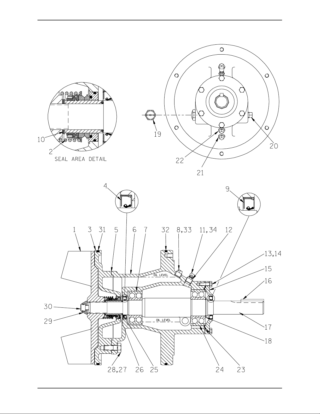
SECTION DRAWING
TSERIESOM--04326
Figure 3. 44163---119 Repair Rotating Assembly
MAINTENANCE & REPAIRPAGE E -- 6
Page 28
TSERIES OM--04326
PARTS LIST
44163---119 Repair Rotating Assembly
ITEM
NO.
1
2
3 SEAL PLATE 12350 10010 1
4
5
6 BEARING HOUSING 38251---510 10000 1
7
8 VENTED PLUG 4823A 15079 1
9
10
11 AIR VENT S1530 --- ------ 1
12 REDUCING BUSHING AP0802 15079 1
13 HEX HD CAPSCREW B0605 1/2 15991 6
14 LOCKWASHER J06 15991 6
15 BEARING CAP 38322---415 10010 1
16
17
18 RETAI NING RING S215 --- --- --- 1
19 SIGHT GAUGE S1471 --------- 1
20 PIPE PLUG P12 15079 1
21 SEAL CAVITY DRAIN PLUG P08 15079 1
22 BEARING HOUSING DRAIN PLUG P08 15079 1
23
24
25
26
27 HEX HD CAPSCREW B1006 15991 4
28 LOCKWASHER J10 15991 4
29
30
31
32
33 SHIPPING PLUG 11495B 15079 1
34 SHIPPING PLUG 11495B 15079 1
PART NAME
IMPELLER 12349 11000 1
SEAL ASSEMBLY 12590 --- ------ 1
OIL SEAL S1917 --- ------ 1
SEAL PLATE GSKT 12350G 20000 1
BALL BEARING 23421---461 --------- 1
OIL SEAL S1917 --- ------ 1
IMPELLER ADJ SHIM SET 5091 17090 REF
SHAFT KEY N0616 15990 1
IMPELLER SHAFT 38515---577 16000 1
BEAR ING CAP O-RING S333 --- --- --- 1
BALL BEARING 23422---412 --------- 1
SHAFT SLEEVE O-RING 25152---026 --------- 1
SHAFT SLEEVE 12359 16000 1
IMPELLER WASHER 10278 15030 1
SOCKET HD CAPSCREW DM1004S 15991 1
SEAL PLATE O-RING S1914 --------- REF
BEARING HOUSING O-RING S1914 --- ------ REF
PART
NUMBER
MAT’L
CODE
QTY
NOT SHOWN:
ROTATING ASSY SHIM SET 48261---030 --------- 6
OPTIONAL:
ADI IMPELLER 12349 1102H 1
ADI SEAL PLATE 12350 1102H 1
INDICATES PARTS RECOMMENDED FOR STOCK
MAINTENANCE & REPAIR PAGE E -- 7
Page 29
OM--04326 TSERIES
PUMP AND SEAL DISASSEMBLY
AND REASSEMBLY
Beforeattempting toopenorservice the
Review all SAFETY information in Section A.
pump:
1. Familiarize yourself with this man-
Follow the instructions on all tags, labels and
decals attached to the pump.
ual.
2. Switch off the engine ignition and
disconnect the positive battery
cable to ensure that the pump will
This pump requires littleservice due to its rugged,
minimum-maintenance design. However, if it becomesnecessarytoinspectorreplacethewearing
parts, followthese instructions which are keyed to
thesectionalviews(seeFigures1, 2 and3)andthe
accompanying parts lists.
remain inoperative.
3. Allowthe pump to completelycool
if overheated.
4. Check the temperature before
opening any covers, plates, or
plugs.
5. Close the suction and discharge
As described on the following pages, this manual
willalert personnelto known procedures which require s pecial attention, to those which could damage equipment, and to those which could be dangerousto personnel. However,this manualcannot
possibly anticipate and provide detailed precautions for every situation that might occur during
maintenanceofthe unit.Therefore,itis the responsibilityof the owner/maintenance personnel to ensure that only safe, established maintenance proceduresare used, andthat anyproceduresnotaddressedinthismanualareperformedonlyafterestablishingthat neitherpersonalsafetynorpump in tegrity are compromised by such practices.
valves.
6. Vent the pump slowly and cautiously.
7. Drain the pump.
Use lifting and moving equipment in
good repair and with adequate capacity
topreventinjuriesto personnel or damage to equipment. Suction and discharge hoses and piping must be removed from the pump before lifting.
Mostservicefunctionsmaybeperformed by drainingthepump andremovingtheback coverassembly.Ifmajorrepairisrequired,thepipingand/or
power source must be disconnected. The following instructions assume complete disassembly is
required.
Before attempting to service the pump, switch off
theengineignition anddisconnect thepositivebatterycabletoensurethatthe pumpwillremaininoperative. Close all valves in the suction and discharge lines.
Forengine disassembly and repair, consult the literature supplied with the engine, or contact your
local Deutz engine representative.
Back Cover And Wear Plate Removal
(Figure 2)
The wear plate(20) and check valve (42)are easily
accessible and may be serviced by removing the
back cover assembly (21). Before attempting to
service the pump, remove the pump casing drain
plug (27) and drain the pump. Clean and reinstall
the drain plug.
Removethehandnuts (33)andpullthe back cover
andassembledwearplatefromthepumpcasing
(1). Inspect the wear plate, and replace it if badly
scoredandworn. Toremovethe wear plate, disengage the hardware (36 and 37).
Inspect the back cover O-ring (28) and replace it if
damaged or worn.
MAINTENANCE & REPAIRPAGE E -- 8
Page 30
Suction Check Valve Removal
(Figure 1)
OM--04326TSERIES
If the check valve assembly (42) is to be serviced,
remove the check valve pin (3), reach through the
backcoveropening, andpullthe completea ssembly from the suction flange.
NOTE
Further disassembly of the check valve is not required sinceitmust bereplaced asacomplete unit.
Individual parts are not sold separately.
Pump Casing Removal
(Figure 1)
It is recommended that the pump(1) beseparated
from the base (75) and gearbox (58) to ease removalofthe rotatingassembly(2, Figure2).Before
attempting to remove the pump, disengage the
piping from the suction and discharge flanges (47
and 52, Figure 2).
Disengage the hardware (68, 69, 70 and 71) and
remove the coupling guard assembly (2). Loosen
theattaching hardware and separate the halvesof
thecoupling(4). Removethehardware (76,77and
78) securing the pump casing to the base.
(Figure 2)
Remove the discharge elbow (52) and gasket (8)
and fill cover assembly (57) and gasket (61) from
the pump casing. Loop a suitable chain or cable
through the discharge port and back out the priming port and attach it to a hoist.
Suction and discharge hoses and pip ingmustbe removed
fromthe pump before lifting. Use lifting and moving
equipment in good repair and with adequate capacity to prevent injuries to
personnel ordamageto equipment.The
bail is intended for use in lifting the
pump assembly only.
Afterthe pumpis removed,tie andtag any leveling
shims used under the casing mounting feet for
ease of reassembly. Remove the coupling halfand
shaft key (16, Figure 3) from the impeller shaft.
Rotating Assembly Removal
(Figure 3)
The rotating assembly may be removed from either side of the casing; however, it is recommendedthat itbe removedthroughthe backcover
opening.
Theimpeller(1) should beloosenedwhile therotating assembly is still secured to the pump casing.
Before loosening theimpeller,remove the sealcavitydrain plug(21) anddrain theseal lubricant.This
willprevent the oil in the seal cavity from escaping
as the impeller isloosened. Clean and reinstallthe
seal cavity drain plug.
Immobilize the impeller by wedging a block of
wood between the vanes and remove the impeller
capscrew and washer (29 and 30). Install the shaft
key (16). Install a lathe dog on the drive end of the
shaft (17) with the “V” notch positioned over the
shaft keyway. Strike the lathe dog sharply in a
counterclockwise direction (when facing the drive
end of the shaft). When the impeller breaks loose,
remove the wood block and lathe dog. Do not fully
unscrew the impeller from the shaft at this time.
(Figure 2)
Make certain the chain or cable is positioned so that the pump will not be damaged,and sothattheloadwillbebalanced.
Use a hoist of sufficient capacity to safely lift the
pump end from the base and move it to a suitable
work area for disassembly.
MAINTENANCE & REPAIR PAGE E -- 9
An optional disassembly tool for removing and installing the rotating assembly is available from the
factory. If improvised tools are used, be sure they
areheavyenough for safeuse and willnotdamage
the pump.
Remove the inner hardware (15 and 16) from the
casing ring (12). If the removal tool is used, follow
Page 31
OM--04326 TSERIES
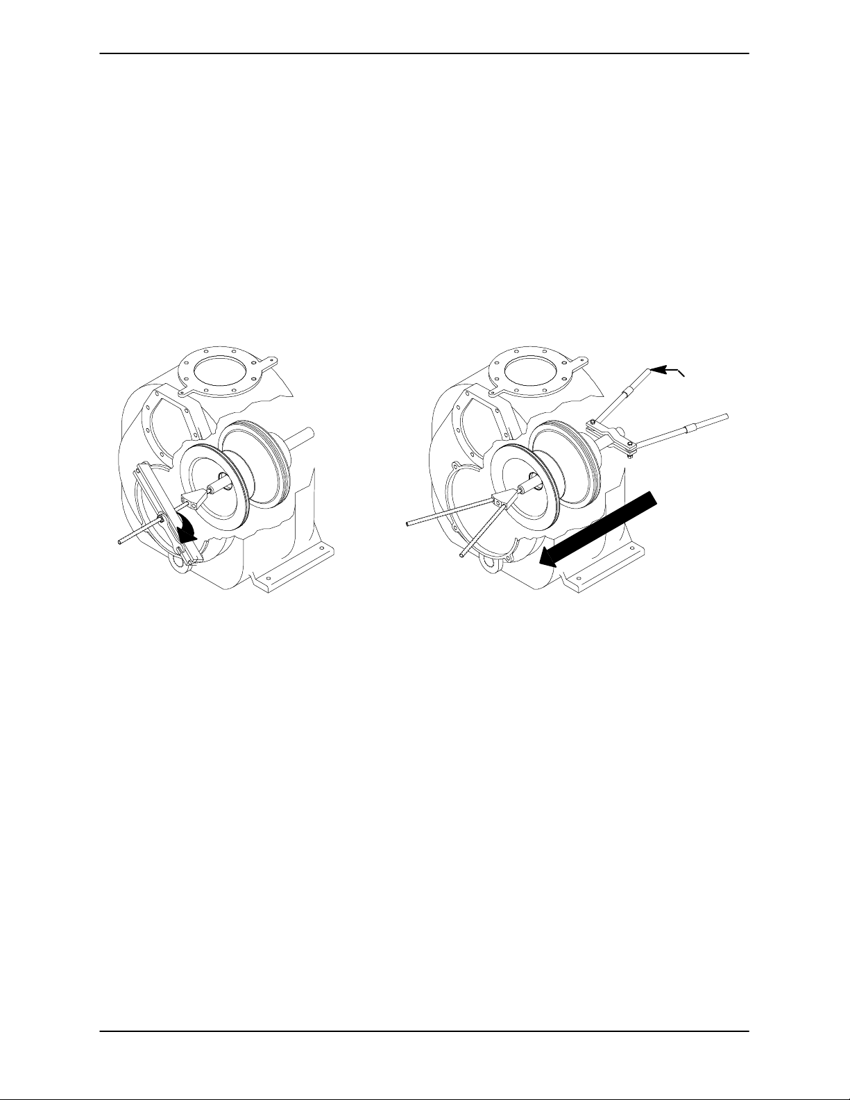
theinstructionspackaged w ith it, andpulltherotating assembly from the pump casing (see Figure 4
forremoval tooluse). Ifthe removaltool is notused,
install three of the inner capscrews in the jacking
holesin the casing ring, and usethem to press the
rotating assembly into the pump casing until the
bearing housing is free.
Remove the jacking screws from the casing ring.
Remove the outer hardware (13 and 14) and shim
sets (11). Separate the casing ring from the pump
casing. Tie and tag the shim sets for ease of reassembly.
After the rotating assembly is loosened, screw a
5/8-18 UNC X 16 inch long threaded rod into the
tapped hole in the impellershaft.Support thedrive
end of the shaft with a 113/16 ” (46 mm) minimum
I.D.pieceofpipe orasetofhandlesasshownin
Figure4,and slidethecomplete rotatingassembly
through the back cover opening. Once free, use a
suitable hoist and sling t o move the rotating assembly to a suitable work area for further disassembly.
ADD PIPE
AS REQUIRED
Figure 4. Removing Rotating Assembly With Tool
Impeller Removal
(Figure 3)
Unscrew the impeller from the shaft in a counterclockwise direction (when facing the impeller). Use
caution when unscrewing the impeller; tension on
theshaft sealspring willbe releasedas the impeller
is removed.
Remove the impelleradjusting shims (10). Tie and
tag the shims or measure and record their thickness for ease of reassembly.
Seal Removal and Disassembly
(Figure 3)
Removethe seal spring. Slide the shaft sleeve (26)
andthe rotating portion of thesealoff the shaftasa
unit.Applyoiltothe sleeveandwork itupunderthe
bellows. Slide the rotating portion of the seal offthe
sleeve.
Remove the shaft sleeve O-ring (25).
Use a stiff wire with a hooked end to remove the
stationary portion of the seal.
An alternate method of removing the stationary
portion of the seal is to remove the hardware (27
and 28) and separate the seal plate(3) and gasket
(5) from the bearing housing (6). Remove the seal
plate O-ring (31). Position the seal plate on a flat
surface withtheimpeller side down. Use awooden
dowel or other suitable tool to press on the back
side of the stationary seat until the seat, O-rings
and stationary element can be removed.
If no further disassembly is required, refer to Seal
Installation.
MAINTENANCE & REPAIRPAGE E -- 10
Page 32
Shaft and Bearing Removal and Disassembly
(Figure 3)
OM--04326TSERIES
When the pump is properly operated and maintained,the bearing housingshouldnot requiredisassembly. Disassemble the shaft and bearings
only when there is evidence of wear or damage.
Shaft and bearing disassembly in the field
is not recommended. These operations
should be performed only in a properly
equipped shop by qualified personnel.
Remove the bearing housing drain plug (22) and
drain the lubricant. Clean and reinstall the drain
plug. Remove the bearing housing O-ring (32).
Disengage the hardware (13 and 14) and remove
the bearing cap (15), O-ring (23) and oil seal (9)
fromtheshaft. Removethe O-ring and using an arbor (or hydraulic) press remove the oil s eal from
the bearing cap.
Most cleaning solvents are toxic and
flammable. Use themonly in a wellventilated area free from excessive heat,
sparks, and flame. Read and follow all
precautions printed on solventcontainers.
Clean the bearings thoroughly in fresh cleaning
solvent.Dry the bearings with filteredcompressed
air and coat with light oil.
Bearings must be kept free of all dirt and
foreign material. Failureto doso will greatly shorten bearing life. Do not spin dry
bearings. This may scratch the balls or
races and cause premature bearing failure.
Rotate the bearings by hand to check for roughnessorbinding and inspect the bearing balls.If rotation is rough or the bearing balls are discolored,
replace the bearings.
Place a block of wood against the impeller end of
the shaft and tap the shaft and assembled bearings (7 and 24) from the bearing housing.
After removing the shaft and bearings, clean and
inspect the bearings in place as follows.
To prevent damage during removal from
the shaft, it is recommended that bearings
be cleaned and inspected in place.Itis
strongly recommended that the bearings
be replaced any time the shaft and bearings are removed.
Clean the bearing housing, shaft and all component parts (except the bearings) with a soft cloth
soaked in cleaning solvent. Inspect the parts for
wear or damage and replace as necessary.
The bearing tolerances provide a tight press fit
onto the shaft and a snug slip fit into the bearing
housing. Replace the bearings, shaft, or bearing
housing if the proper bearing fit is not achieved.
If bearing replacement is required, remove the
bearing retaining ring (18) from the impeller shaft,
anduseabearingpullertoremovetheinboardand
outboard bearings from the shaft.
Press the inboard oil seal (4) from the bearing
housing bore.
Shaftand BearingReassembly and Installation
(Figure 3)
Inspect the shaft for distortion, nicks or scratches,
or for thread damage on the impeller end. Dress
small nicks and burrs with a fine file or emery cloth.
Replace the shaft if defective.
Positiontheinboardoilseal(4)inthe bearinghousing bore with the lip positioned as shown in Figure
MAINTENANCE & REPAIR PAGE E -- 11
Page 33
OM--04326 TSERIES
3. Press the oil seal into the housing until it is fully
seated.
To prevent damage during removal from
the shaft, it is recommended that bearings
be cleaned and inspected in place.Itis
strongly recommended that the bearings
be replaced any time the shaft and bearings are removed.
The bearings may be heated to ease installation.
An induction heater , hot oil bath, electric oven, or
hotplatemaybeusedtoheatthebearings.Bearings should never be heated with a direct flameor
directly on a hot plate.
NOTE
Ifahotoil bathis usedtoheat thebearings, boththe
oil and the container must be absolutely clean. If
the oil has been previously used, it must be thor-
oughly filtered.
Heat the bearings to a uniform temperature no
higher than 250_ F (120_ C), and slide t he bear-
ingsontothe shaft, oneat atime, untiltheyarefully
seated. This should be done quickly, in one continuous motion, to prevent the bearings from cooling and sticking on the shaft.
Use caution when handling hot bearings to prevent burns.
NOTE
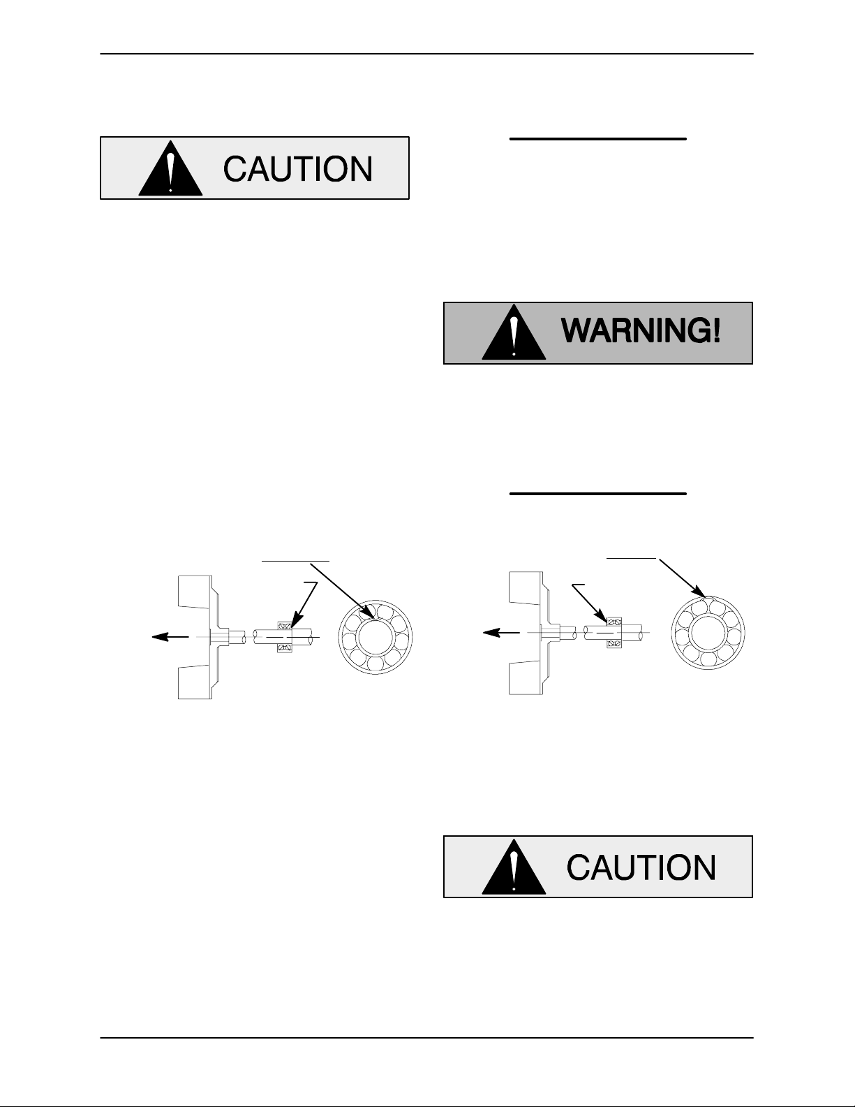
Positionthe inboardbearing(7) on theshaftas indicated by the following illustration.
BALL LOADING
GROOVE POSITIONED
AWAY FROM
LOADING
GROOVE
DIRECTIONOF
THRUST
INSTALLATION OF NEW DEPARTURE OR
BCA/FEDERAL MOGAL 5300W SERIES BEARINGS
(OPEN OR ENCLOSED IMPELLERS)
IMPELLER
Figure 5. Inboard Bearing Positioning
Afterthe bearingshave beeninstalled and allowed
to cool,check to ensure that they have not moved
away from the shaft shoulders in shrinking. If
movement has occurred, use a suitable sized
sleeve and a press to reposition the bearings
against the shaft shoulders.
If heating the bearings is not practical, use a suitablesizedsleeve,andanarbor(orhydraulic)press
to install the bearings on the shaft.
BALL LOADING
DIRECTIONOF
THRUST
INSTALLATIONOF MRC/SKF 5300M OR
(OPEN OR ENCLOSED IMPELLERS)
GROOVE POSITIONED
TOWARD
LOADING
GROOVE
FAFNIR 5300W SERIES BEARINGS
IMPELLER
When installing the bearings onto the
shaft, never press or hit against the outer
race, balls, or ball cage. Press only onthe
inner race.
Secure the outboard bearing on the shaft with the
bearing retaining ring (18).
MAINTENANCE & REPAIRPAGE E -- 12
Page 34
OM--04326TSERIES
Slide the shaft and assembled bearings into the
bearing housing until the retaining ring on the outboard bearing seats against the bearing housing.
When installing the shaftand bearings into
the bearing bore, push against the outer
race. Never hit the balls or ball cage.
Press the outboard oil seal (9) into the bearingcap
(15) with the lip positioned as shown in Figure 3.
Replace the bearing cap O-ring (23), and secure
the bearing cap with the hardware (13 and 14).
Lubricate the bearing housing as indicated in LU-
BRICATION.
Seal Reassembly and Installation
(Figures 3 and 6)
Cleanthe seal cavity and shaft witha cloth soaked
in fresh cleaning solvent.
precautions printed on solventcontainers.
The seal is notnormally reused because wear patterns on the finished faces cannot be realigned
during reassembly. This could result in premature
failure.Ifnecessarytoreuse anoldsealinanemergency, carefully wash all metallic parts in fresh
cleaning solvent and allow to dry thoroughly.
Handlethe seal parts w ith extreme care to prevent
damage. Be careful not to contaminate precision
finished faces; even fingerprints on the faces can
shortenseallife.Ifnecessary,cleanthefaceswitha
non-oilbased solvent and a clean, lint-free tissue.
Wipe lightly in a concentric pattern to avoid
scratching the faces.
Inspect the seal components for wear, scoring,
grooves,andother damage that mightcause leakage.Clean and polishtheshaft sleeve,orreplaceit
if there are nicks or cuts on either end. If any components are worn, replace the complete seal;
never mix old and new seal parts.
If a replacement seal is being used, remove it from
the container and inspect the precision finished
faces to ensure that they are free of any foreign
matter.
Most cleaning solvents are toxic and
flammable. Use themonly in a wellventilated area free from excessive heat,
sparks, and flame. Read and follow all
To ease installation of the seal, lubricate the bellows and stationary seat O-rings with water or a
very small amount of oil, and apply a drop of light
lubricating oil on the finished faces. Assemble the
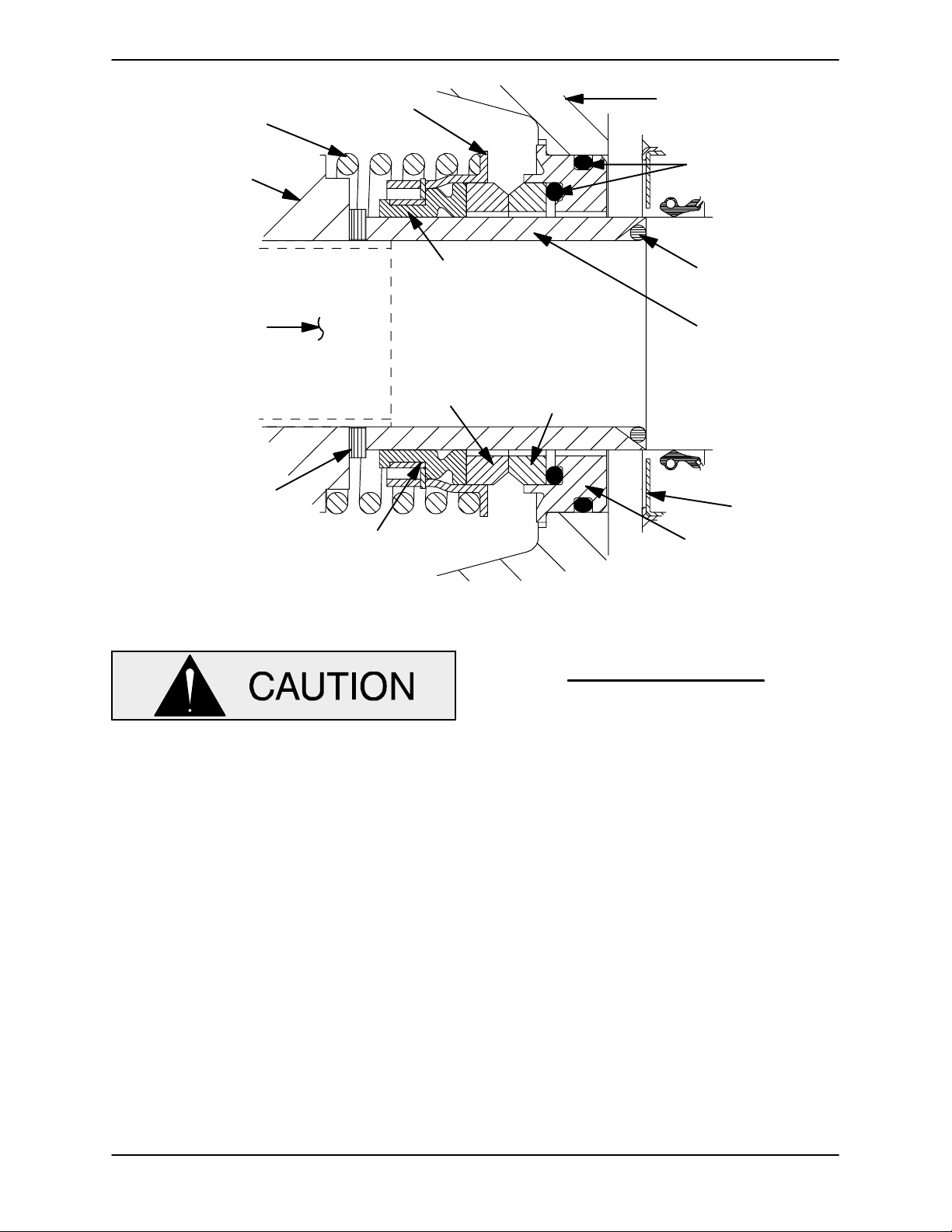
seal as follows, (see Figure 6).
MAINTENANCE & REPAIR PAGE E -- 13
Page 35
OM--04326 TSERIES
SPRING
IMPELLER
IMPELLER
SHAFT
IMPELLER SHIMS
RETAINER
BELLOWS
ELEMENT ELEMENT
DRIVE BAND
SEAL PLATE
O-RINGS
SEAL SLEEVE
O-RING
STATIONARYROTATING
OIL SEAL
STATIONARY
SEAT
Figure 6. 12590 Seal Assembly
This seal is not designed for operation at
temperatures above 160_F(71_C). Do not
use at higher operating temperatures.
Lubricate the stationary seat O-ringswith water or
light oil, and install them in the stationary seat. Install the stationary seal element in the stationary
seat. Press this stationary subassembly into the
front of the seal plate until it seats squarely against
theboreshoulder.
Install the seal plate gasket (5). Position the seal
plateandstationaryseatoverthe shaft,andsecure
ittothe bearinghousingwiththe hardware(27and
28). Be careful not t o damage the stationary element on the shaft threads.
installation of the rotating seal components.
Lubricatetheshaftsleevewithasmall amount of
light oil and slide the rotating subassembly (consisting of rotating element, bellows and retainer),
onto the sleeve until the rotating element is just
flush with the undercut end of the sleeve.
Installthe O-ring(25) which s eals the sleeve to the
shaftshoulder. Slidethesleeveandsubassembled
seal onto the shaft until the seal faces contact.
Continue to push the sleeve through the seal until
the undercut end seats against the O-ring and
shaft shoulder.
Install the seal spring. Lubricate the seal as indicated in LUBRICATION aftertheimpellerisinstalled.
Impeller Installation
NOTE
It is recommended that a tapered sleeve be installedoverthethreadsoftheimpellershaftto ease
(Figure 3)
Inspect the impeller, and replace it if cracked or
badly worn. Inspectthe impeller and shaft threads
MAINTENANCE & REPAIRPAGE E -- 14
Page 36
OM--04326TSERIES
for dirt or damage, and clean or dress the threads
as required.
The shaft and impeller threads must be
completelycleanbeforereinstalling theimpeller. Even the slightest amount of dirt on
thethreads can causetheimpeller to seize
to the shaft, making future removal difficult
or impossible without damage to the impellerorshaft.
Install the same thickness of impeller adjusting
shims (10) as previously removed, and screw the
impeller onto the shaft until tight.
NOTE
At the s lightest sign of binding, immediately back
the impeller off, and check the threads for dirt. Do
not try to force the impeller onto the shaft.
A clearance of .025 to .040 inch (0,64 to 1,02 mm)
between the impeller and the seal plate is recommended for maximum pump efficiency. Measure
thisclearance, and add or remove impeller adjusting shims as required.
NOTE
If the rotating assembly has been installed in the
pump casing, this clearance may be measured by
reaching through the priming port with a feeler
gauge.
Afterthe rotating assembly is installedin thepump
casing, coat the threads of the impeller capscrew
(30) with ‘Never---Seez’ or equivalent compound,
and install theimpellerwasher (29) and capscrew;
torque the capscrew to 90 ft. lbs. (1080 in. lbs. or
12,4 m. kg.).
Rotating Assembly Installation
(Figure 2)
Install the bearing housing and seal plate O-rings
(18 and 19), and lubricate them with light grease.
Ease the rotating assembly into the pump casing
using the installation tool. Be careful not to damage the O -rings.
Install the pump casing ring (12), and secure it to
therotatingassemblywiththeinnerhardware(15
and 16).
NOTE
The inner capscrews are 1/4 inch (3,2 mm) shorter
than the outer capscrews.
Install an equal thickness of rotating assembly
shims(11)underthepumpcasingring,andsecure
the ring to the pump casing with the outer hardware (13 and 14).
NOTE
If the pump has been completely disassembled, it
is recommended that the suction check valve (42),
wear plate (20) and back cover assembly (21) be
reinstalled at this point. The back cover and wear
plate must be in place to adjust the impeller face
clearance.
A clearance of .010 to .020 inch (0,25 to 0,51 mm)
betweentheimpellerandthewearplateisalsorecommended for maximum pump efficiency. This
clearance can be obtained by removing an equal
amount of shims from each rotating assembly
shimset (11) until the impeller scrapes against the
wear plate when the shaft is turned. Preload the
shaft in the direction of the impeller when
checking this clearance. After the impeller
scrapes,addapproximately.010inch(0,25 mm)of
shims to each shim set.
NOTE
Analternatemethodof adjusting thisclearance isto
reachthrough the priming port with a feeler gauge
and measure the gap. Add or subtract rotating assembly shims accordingly.
Pump Casing Installa tion
(Figure 1)
Usingachain or cableandasuitablehoist,carefully position the pump (1) on the base (75). Install
any leveling shims used under the casing mountingfeet,and securethe casing tothe base withthe
hardware (76, 77 and 78).
Installtheshaftkey(16,Figure3)andthehalfofthe
coupling (4) on the impeller shaft, and align the
MAINTENANCE & REPAIR PAGE E -- 15
Page 37
OM--04326 TSERIES
coupling halves as described in INSTALLATION,
SectionB. Install the couplingguard assembly(2)
andsecureitwiththe hardware(68, 69,70 and71).
(Figure 2)
Removethe lifting deviceand install the discharge
elbow and gasket (52 a nd 8).
NOTE
Whenreinstallingthesuctionor dischargeflanges,
replace the respective gaskets and apply ‘Perma tex Aviation No. 3 Form-A-Gasket’ or equivalent
compound to the mating surfaces.
Reinstall the fill cover assembly (57) and gasket
(61)afterthepumpiscompletelyreassembledand
primed.
Suction Check Valve Installation
Back Cover Installation
(Figure 2)
If the wear plate (20) was removed for replacement, carefully center it on the back cover and secure it with the hardware (36 and 37). The wear
plate must be concentric to prevent binding when
the back cover is installed.
Replacetheback cover O-ring(28),and lubricateit
withagenerousamountofNo.2grease.Cleanany
scale or debris from the contacting surfaces in the
pumpcasingthat mightinterfereorprevent a good
seal with the back cover. Slide the back cover assembly into the pump casing. Be sure the wear
plate does not scrape against the impeller.
NOTE
To ease future disassembly, apply a film of grease
or ‘Never-Seez’ on the back cover shoulder, or any
surface which contacts the pump casing. This action will reduce rust and scale build-up.
(Figure 2)
Inspect the check valve assembly, and replace it if
badly worn.
NOTE
The check valve assembly must be replaced as a
complete unit. Individual parts are not sold separately.
Reach through thebackcover opening with theassembled check valve (42), and position the check
valve adaptor in the mounting slot in the suction
flange (40). Align the adaptor with the flange hole,
and secure the assembly with the check valve pin
(3).
NOTE
If the suction or discharge flanges were removed,
replace the respective gaskets, apply ‘Permatex
Aviation No. 3 Form-A-Gasket’ or equivalent compound to the mating surfaces, and secure them to
the pump casing with the attaching hardware.
Secure the backcover assembly by tightening the
hand nuts (33) evenly. Do not over-tighten the
hand nuts; they shouldbe just tight enough to ensure a good seal at the back cover shoulder. Be
sure the wear plate does not bind against the casing.
PRESSURE RELIEF VALVE
MAINTENANCE
(Figure 2)
The back cover is equipped with a pressure relief
valve(25)to provideadditionalsafety for the pump
and operator (refer to Liquid Temperature And
Overheating in OPERATION).
Itis recommended thatthepressurerelief valveas sembly be replaced at each overhaul, or any time
thepumpoverheatsandactivatesthevalve.Never
replace this valve with a substitute which has not
been specified or provided by the Gorman-Rupp
Company.
Periodically, the valve should be removed for inspection and cleaning. When reinstalling the relief
valve, apply ‘Loctite Pipe Sealant With Teflon No.
592’, or equivalent compound, on the relief valve
MAINTENANCE & REPAIRPAGE E -- 16
Page 38
OM--04326TSERIES
threads. Position the valve as shown in Figure 2,
with the discharge port pointing down.
Final Pump Assembly
(Figure 1)
Be sure the pump is secure to the base and engine.
Installthe suction anddischarge linesand openall
valves. Makecertainthatallpipingconnectionsare
tight, properly supported and secure.
Be sure the pump and engine have been properly
lubricated, see LUBRICATION.
Fill the pump casing with clean liquid. Reinstall the
fillcoverand tighten it. Refer to OPERATION,Section C, before putting the pump back into service.
LUBRICATION
Seal Assembly
(Figure 3)
Before starting the pump, remove the vented plug
(8) and fill the seal cavity with approximately 90
ounces(2,7 liters) of SAENo. 30 non-detergent oil.
Cleanandreinstalltheventedplug.Maintaintheoil
at this level.
Bearings
larlythroughthesight gauge(19)andmaintainit at
the middle of the gauge. When lubrication is required, add SAE No. 30 non-detergent oil through
theholefortheairvent(11).Do not over-lubricate.
Over-lubrication can cause the bearings to overheat, resulting in premature bearing failure.
NOTE
Thewhitereflectorinthesightgaugemust bepositioned horizontally to provide proper drainage.
Under normal conditions, drain the bearing housingonce each year and refillwith approximately32
ounces(1liter)ofclean oil.Changethe oil morefre quently if the pump is operated continuouslyor installed in an environment with rapid temperature
change.
Monitor the condition of the bearing lubricantregularly for evidenceof rust or moisture condensation. This is especially important in areas where variable hot and
cold temperatures are common.
Forcoldweatheroperation,consultthefactoryora
lubricant supplier for the recommended grade of
oil.
(Figure 2)
The bearing housing was fully lubricated when
shipped from the factory. Check the oil level regu-
MAINTENANCE & REPAIR PAGE E -- 17
Engine
Consult the literature supplied with the engine, or
contact your local Deutz representative.
Page 39

For U.S. and International Warranty Information,
Please Visit www.grpumps.com/warranty
or call:
U.S.: 419−755−1280
International: +1−419−755−1352
For Canadian Warranty Information,
Please Visit www.grcanada.com/warranty
or call:
519−631−2870
THE GORMAN-RUPP COMPANY D MANSFIELD, OHIO
GORMAN-RUPP OF CANADA LIMITED D ST. THOMAS, ONTARIO, CANADA
 Loading...