

GORMAN-RUPP PUMPS Super T Series, Super T6A60S-ZPP857-ESP Installation, Operation, And Maintenance Manual With Parts List
Page 1
OM-07174-01
June 15, 2018
INSTALLATION, OPERATION,
AND MAINTENANCE MANUAL
WITH PARTS LIST
SUPER T SERIESr
ENVIRONMENTAL SILENT PUMP
MODEL
T6A60S-ZPP857-ESP
GORMAN‐RUPP PUMPS
www.grpumps.com
e2018 Gorman‐Rupp Pumps Printed in U.S.A.
Page 2

Register your new
Gorman‐Rupp pump online at
www.grpumps.com
Valid serial number and e‐mail address required.
RECORD YOUR PUMP MODEL AND SERIAL NUMBER
Please record your pump model and serial number in the
spaces provided below. Your Gorman‐Rupp distributor
needs this information when you require parts or service.
Pump Model:
Serial Number:
Page 3

TABLE OF CONTENTS
INTRODUCTION PAGE I - 1.................................................
SAFETY ‐ SECTION A PAGE A - 1............................................
INSTALLATION - SECTION B PAGE B - 1....................................
Pump Dimensions PAGE B - 1.....................................................
PREINSTALLATION INSPECTION PAGE B - 1............................................
Battery Specifications And Installation PAGE B - 2....................................
SAFETY AND CONFORMANCE PAGE B - 2.............................................
POSITIONING PUMP PAGE B - 3.......................................................
Lifting PAGE B - 3.................................................................
Mounting PAGE B - 3.............................................................
Clearance PAGE B - 3.............................................................
NATURAL GAS FUEL PAGE B - 3......................................................
LPG FUEL PAGE B - 3................................................................
FUEL TANK (LPG ONLY) PAGE B - 4....................................................
REGULATORS (NATURAL GAS) PAGE B - 4.............................................
REGULATORS (LP GAS) PAGE B - 4...................................................
CONNECTING FUEL SUPPLY LINE TO THE UNIT PAGE B - 5.............................
CHANGING FUEL TYPE PAGE B - 5....................................................
SUCTION AND DISCHARGE PIPING PAGE B - 5.........................................
Materials PAGE B - 5..............................................................
Line Configuration PAGE B - 5......................................................
Connections to Pump PAGE B - 5..................................................
Gauges PAGE B - 5...............................................................
SUCTION LINES PAGE B - 6...........................................................
Fittings PAGE B - 6...............................................................
Strainers PAGE B - 6..............................................................
Sealing PAGE B - 6...............................................................
Suction Lines In Sumps PAGE B - 6.................................................
Suction Line Positioning PAGE B - 6................................................
SUBMERSIBLE TRANSDUCER PAGE B - 7..............................................
DISCHARGE LINES PAGE B - 8........................................................
Siphoning PAGE B - 8.............................................................
Valves PAGE B - 8................................................................
OPERATION - SECTION C PAGE C - 1......................................
OPERATION PAGE C - 1..............................................................
STARTING PAGE C - 1................................................................
PRIMING PAGE C - 1.................................................................
OPTIONAL EPS CONTROL PAGE C - 2.................................................
Features PAGE C - 2..............................................................
Functional Description PAGE C - 2..................................................
EPS Functions PAGE C - 3.........................................................
EPS Calibration PAGE C - 4........................................................
Zero Adjustment PAGE C - 4.......................................................
Span Adjustment PAGE C - 4......................................................
Level Adjustment PAGE C - 4......................................................
i
Page 4

TABLE OF CONTENTS
(continued)
Horn Delay PAGE C - 4............................................................
ROUTINE OPERATION PAGE C - 4.....................................................
Lines With a Bypass PAGE C - 5....................................................
Lines Without a Bypass PAGE C - 5.................................................
OPERATION IN EXTREME HEAT PAGE C - 5............................................
OPERATIONAL CHECKS PAGE C - 5...................................................
Leakage PAGE C - 5..............................................................
Pump Vacuum Check PAGE C - 5..................................................
Liquid Temperature And Overheating PAGE C - 5.....................................
Strainer Check PAGE C - 6.........................................................
STOPPING PAGE C - 6................................................................
Manual Stopping PAGE C - 6.......................................................
Automatic Stopping PAGE C - 6....................................................
Safety Shutdown System PAGE C - 6...............................................
PERIODIC CHECKS PAGE C - 6.......................................................
Seal Cavity and Bearing Lubrication PAGE C - 6......................................
Bearing Temperature Check PAGE C - 6.............................................
Engine Fuel Filter PAGE C - 7......................................................
Engine Oil PAGE C - 7.............................................................
COLD WEATHER PRESERVATION PAGE C - 7...........................................
TROUBLESHOOTING - SECTION D PAGE D - 1..............................
PREVENTIVE MAINTENANCE PAGE D - 3...............................................
PUMP MAINTENANCE AND REPAIR ‐ SECTION E PAGE E - 1.................
STANDARD PERFORMANCE CURVE PAGE E - 1........................................
PARTS LISTS:
Pump Model PAGE E - 3..........................................................
Pump Model (Cont'd) PAGE E - 5...................................................
Pump End Assembly PAGE E - 7...................................................
Repair Rotating Assembly PAGE E - 9...............................................
Coupling Kit PAGE E - 10...........................................................
PUMP AND SEAL DISASSEMBLY AND REASSEMBLY PAGE E - 11.........................
Back Cover And Wear Plate Removal PAGE E - 12.....................................
Suction Check Valve Removal PAGE E - 12...........................................
Separating Intermediate and Coupling Kit From Engine PAGE E - 12.....................
Loosening Impeller PAGE E - 13.....................................................
Rotating Assembly Removal PAGE E - 13.............................................
Impeller Removal PAGE E - 14......................................................
Seal Removal PAGE E - 14..........................................................
Shaft and Bearing Removal and Disassembly PAGE E - 14.............................
Shaft and Bearing Reassembly and Installation PAGE E - 15............................
Seal Installation PAGE E - 16........................................................
Impeller Installation and Adjustment PAGE E - 19......................................
Rotating Assembly Installation PAGE E - 19...........................................
Suction Check Valve Installation PAGE E - 19.........................................
Back Cover Installation And Adjustment PAGE E - 20..................................
Securing Pump and Coupling Kit to Engine PAGE E - 21...............................
PRESSURE RELIEF VALVE MAINTENANCE PAGE E - 21..................................
Final Pump Assembly PAGE E - 22..................................................
ii
Page 5

TABLE OF CONTENTS
(continued)
LUBRICATION PAGE E - 22.............................................................
Seal Assembly PAGE E - 22.........................................................
Bearings PAGE E - 22..............................................................
Engine PAGE E - 22................................................................
iii
Page 6
SUPER T SERIES
OM-07174
INTRODUCTION
Thank You for purchasing a Gorman‐Rupp pump.
Read this manual carefully to learn how to safely
install and operate your pump. Failure to do so
could result in personal injury or damage to the
pump.
Because pump installations are seldom identical,
this manual cannot possibly provide detailed in
structions and precautions for every aspect of
each specific application. Therefore, it is the re
sponsibility of the owner/installer of the pump to
ensure that applications not addressed in this
manual are performed only after establishing that
neither operator safety nor pump integrity are com
promised by the installation. Pumps and related
equipment must be installed and operated ac
cording to all national, local and industry stan
dards.
If there are any questions regarding the pump or
its application which are not covered in this man
ual or in other literature accompanying this unit,
please contact your Gorman‐Rupp distributor, or
The Gorman‐Rupp Company:
HAZARD AND INSTRUCTION
DEFINITIONS
The following are used to alert maintenance per
sonnel to procedures which require special atten
tion, to those which could damage equipment, and
to those which could be dangerous to personnel:
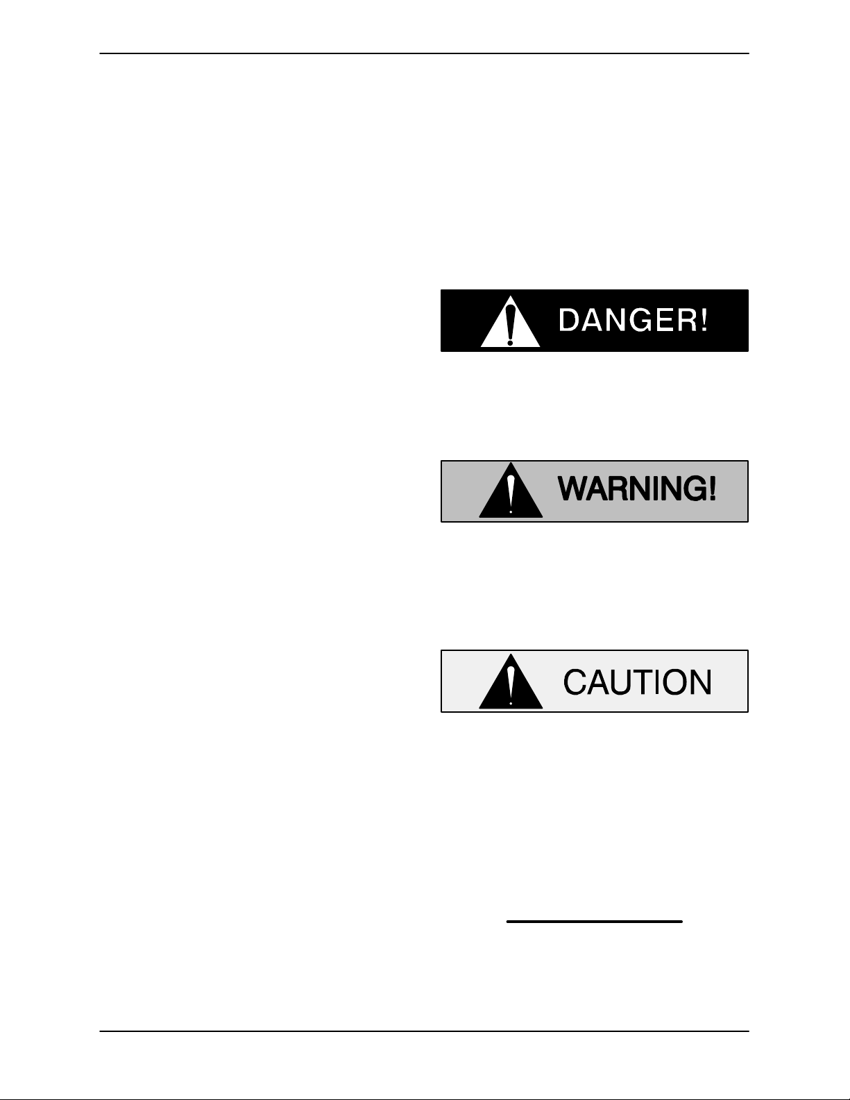
Immediate hazards which WILL result in
severe personal injury or death. These
instructions describe the procedure re
quired and the injury which will result
from failure to follow the procedure.
Hazards or unsafe practices which
COULD result in severe personal injury
or death. These instructions describe
the procedure required and the injury
which could result from failure to follow
the procedure.
The Gorman‐Rupp Company
P.O. Box 1217
Mansfield, Ohio 44901-1217
Phone: (419) 755-1011
or:
Gorman‐Rupp of Canada Limited
70 Burwell Road
St. Thomas, Ontario N5P 3R7
Phone: (519) 631-2870
For information or technical assistance on the
power source, contact the power source manufac
turer's local dealer or representative.
Hazards or unsafe practices which COULD
result in minor personal injury or product
or property damage. These instructions
describe the requirements and the possi
ble damage which could result from failure
to follow the procedure.
NOTE
Instructions to aid in installation, operation, and
maintenance or which clarify a procedure.
PAGE I - 1INTRODUCTION
Page 7
SUPER T SERIES
OM-07174
SAFETY ‐ SECTION A
This information applies to Super T Se
riesr engine driven pumps. Refer to the
manual accompanying the engine be
fore attempting to begin operation.
Because pump installations are seldom
identical, this manual cannot possibly
provide detailed instructions and pre
cautions for each specific application.
Therefore, it is the owner/installer's re
sponsibility to ensure that applications
not addressed in this manual are per
formed only
after establishing that nei
ther operator safety nor pump integrity
are compromised by the installation.
Before attempting to open or service the
pump:
1. Familiarize yourself with this man
ual.
2. Shut down the engine, remove the
key and disconnect the positive
battery cable to ensure that the
pump will remain inoperative.
3. Allow the pump to completely cool
if overheated.
4. Check the temperature before
opening any covers, plates, or
plugs.
5. Close the suction and discharge
valves.
6. Vent the pump slowly and cau
tiously.
7. Drain the pump.
the positive battery cable before per
forming any maintenance. Failure to do
so may result in serious personal injury.
This pump is designed to handle dirty
water containing specified entrained
solids. Do not attempt to pump volatile,
corrosive, or flammable liquids which
may damage the pump or endanger per
sonnel as a result of pump failure.
Death or serious personal injury and
damage to the pump or components
can occur if proper lifting procedures
are not observed. Make certain that
hoists, chains, slings or cables are in
good working condition and of suffi
cient capacity and that they are posi
tioned so that loads will be balanced
and the pump or components will not be
damaged when lifting. Suction and dis
charge hoses and piping must be re
moved from the pump before lifting. Lift
the pump or component only as high as
necessary and keep personnel away
from suspended objects.
After the unit has been installed, make
certain that the pump and all piping or
hose connections are tight, properly
supported and secure before operation.
This pump is equipped with an automat
ic starting system, and is subject to au
tomatic restart. Keep hands and cloth
ing away from the unit to prevent injury
during automatic operation. Disconnect
Do not operate the pump against a
closed discharge valve for long periods
PAGE A - 1SAFETY
Page 8
SUPER T SERIESOM-07174
of time. If operated against a closed dis
charge valve, pump components will
deteriorate, and the liquid could come
to a boil, build pressure, and cause the
pump casing to rupture or explode.
Do not remove plates, covers, gauges,
pipe plugs, or fittings from an over
heated pump. Vapor pressure within the
pump can cause parts being disen
gaged to be ejected with great force. Al
low the pump to cool before servicing.
Do not operate an internal combustion
engine in an explosive atmosphere.
When operating internal combustion
engines in an enclosed area, make cer
tain that exhaust fumes are piped to the
outside. These fumes contain carbon
monoxide, a deadly gas that is color
less, tasteless, and odorless.
precautions outlined by the National
Fire Protection Association when de
signing and installing the system. Make
certain that the regulators and fuel lines
are of the proper size and capacity for
the system, and that all fuel lines are se
curely connected and free of leaks.
Fuel used by internal combustion en
gines presents an extreme explosion
and fire hazard. Make certain that all
fuel lines are securely connected and
free of leaks.
Never tamper with the governor to gain
more power. The governor establishes
safe operating limits that should not be
exceeded. Refer to the performance
curve in Section E for the maximum con
tinuous operating speed for this pump.
Pumps and related equipment must be in
Natural gas presents an extreme explo
sion and fire hazard. Follow all safety
PAGE A - 2 SAFETY
stalled and operated according to all na
tional, local and industry standards.
Page 9
SUPER T SERIES OM-07174
INSTALLATION - SECTION B
Review all SAFETY information in Section A.
Since pump installations are seldom identical, this
section offers only general recommendations and
practices required to inspect, position, and ar
range the pump and piping.
Most of the information pertains to a standard
static lift application where the pump is positioned
above the free level of liquid to be pumped.
If installed in a flooded suction application where
the liquid is supplied to the pump under pressure,
some of the information such as mounting, line
configuration, and priming must be tailored to the
OUTLINE DRAWING
112.58
APPROX
[ 2859,7]
[ 578,7 ]
specific application. Since the pressure supplied
to the pump is critical to performance and safety,
be sure to limit the incoming pressure to 50% of the
maximum permissible operating pressure as
shown on the pump performance curve.
For further assistance, contact your Gorman‐Rupp
distributor or the Gorman‐Rupp Company.
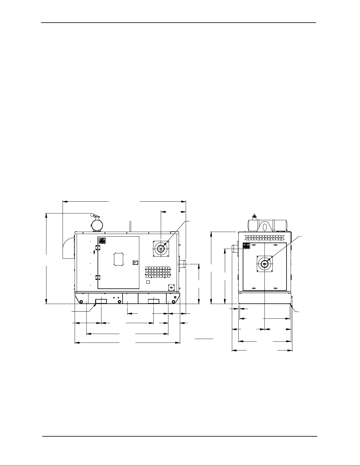
Pump Dimensions
See Figure 1 for the approximate physical dimen
sions of this pump.
22.78
DISCHARGE:
6.00−8 NPT
POWERED BY: ZENITH ZPP857 (NATURAL GAS/LP GAS) ENGINE
SUCTION:
6.00−8
NPT
82.77
[ 2102,5]
APPROX
4.00/[101,6] X 10.00/[254,0]
FORK LIFT POCKET
2 PLACES
24.00
[ 609,6]
48.00
[ 1219,2]
[ 1900,9]
[ 2438,4]
74.84
96.00
37.42
[ 950,5 ]
Figure 1. Pump Model T6A60S-ZPP857-ESP
PREINSTALLATION INSPECTION
The pump assembly was inspected and tested be
fore shipment from the factory. Before installation,
inspect the pump for damage which may have oc
curred during shipment. Check as follows:
65.69
[ 1668,5]
50.26
36.35
[ 923,4]
16.05
[ 407,7 ]
10.59
[ 268,9 ]
DIMENSIONS:
INCHES
[MILLIMETERS]
[ 1276,5]
1.00
[ 25,4 ]
46.00
[ 1168,4]
30.02
[ 762,4 ]
APPROX
55.12
[ 1400,2]
48.00
[ 1219,2]
APPROX
24.00
[ 609,6]
.75/[19,0] DIA
6 HOLES
a. Inspect the pump assembly for cracks, dents,
damaged threads, and other obvious dam
age.
b. Check for and tighten loose attaching hard
ware. Since gaskets tend to shrink after dry
PAGE B - 1INSTALLATION
Page 10

OM-07174 SUPER T SERIES
ing, check for loose hardware at mating sur
faces.
c. Carefully read all tags, decals, and markings
on the pump assembly, and perform all duties
indicated.
d. Check levels and lubricate as necessary. Re
fer to LUBRICATION in the MAINTENANCE
AND REPAIR section of this manual and per
form duties as instructed.
e. If the pump and
engine have been stored for
more than 12 months, some of the compo
nents or lubricants may have exceeded their
maximum shelf life. These must be inspected
or replaced to ensure maximum pump serv
ice.
If the maximum shelf life has been exceeded, or if
anything appears to be abnormal, contact your
Gorman‐Rupp distributor or the factory to deter
mine the repair or updating policy. Do not put the
pump into service until appropriate action has
been taken.
sion. Connect and tighten the positive cable first,
then the negative cable.
SAFETY AND CONFORMANCE
All aspects of the design and installation of the fuel
supply system must be evaluated in terms of safety
to personnel and equipment, and conformance to
all applicable codes.
Battery Specifications And Installation
Unless otherwise specified on the pump order, the
engine battery was not included with the unit. Re
fer to the following specifications when selecting a
battery.
Table 1. Battery Specifications
Reserve
Capacity
@ 80_ F
(Minutes)
175
Amp/
Hr.
Rating
95
Approx.
Overall
Dims.
(Inches)
13L
x
7W
x
9.5H
Voltage
12 Volts
Cold
Crank
Amps
@ 0_ F
950
Before installing the battery, clean the positive and
negative cable connectors, and the battery termi
nals. Secure the battery by tightening the
holddown brackets. The terminals and clamps
may be coated with petroleum jelly to retard corro
Natural Gas and Liquefied Petroleum
Gas (LPG) presents an extreme explo
sion and fire hazard. Follow all safety
precautions outlined by the National
Fire Protection Association when de
signing and installing the system. Make
certain that the regulators and fuel lines
are of the proper size and capacity for
the system, and that all fuel lines are se
curely connected and free of leaks.
Before installing the system:
1. Check all state and local codes pertaining to
installations of stationary combustion engines
and fuel systems.
2. Consult the following National Fire Protection
Association pamphlet:
NFPA No. 37 - Stationary Combustion
Engines/Gas Turbines
NFPA No. 54 - National Fuel Gas Code Hand
book.
PAGE B - 2 INSTALLATION
Page 11
SUPER T SERIES OM-07174
NFPA No. 37 - Liquefied Petroleum Gas Stor
age and Handling.
Copies may be ordered from:
National Fire Protection Association
1 Batterymarch Park
Quincy, Massachusets 02269
POSITIONING PUMP
Lifting
Death or serious personal injury and
damage to the pump or components
can occur if proper lifting procedures
are not observed. Make certain that
hoists, chains, slings or cables are in
good working condition and of suffi
cient capacity and that they are posi
tioned so that loads will be balanced
and the pump or components will not be
damaged when lifting. Suction and dis
charge hoses and piping must be re
moved from the pump before lifting. Lift
the pump or component only as high as
necessary and keep personnel away
from suspended objects.
Pump unit weights will vary depending on the
mounting and drive provided. Check the shipping
tag on the unit packaging for the actual weight, and
use lifting equipment with appropriate capacity.
Drain the pump and remove all customer‐installed
equipment such as suction and discharge hoses
or piping before attempting to lift existing, installed
units.
Mounting
To ensure sufficient lubrication to the engine, do
not position the pump and engine more than 15
off horizontal for continuous operation. The pump
and engine may be positioned up to 30_ off hori
zontal for intermittent operation only; however,
the engine manufacturer should be consulted for
continuous operation at angles greater than 15_.
Clearance
When positioning the pump, allow a minimum
clearance of 18 inches (457,2 mm) in front of the
enclosure suction cover to permit removal of the
cover and easy access to the pump.
NATURAL GAS FUEL
The amount of natural gas fuel required for the en
gine is measured in cubic feet per hour. This is cal
culated from the BTU (British Thermal Unit) con
tent of the natural gas supplied, and the horsepow
er required to drive the pump. This unit requires
1,141 CF/hr of natural gas with 1000 BTU con
tent at 10 inches of water column. The BTU con
tent of gas varies in the United States, therefore, it
will be necessary to contact your local gas supplier
to determine the BTU content of the natural gas in
your area.
When burning natural gas having a BTU content of
1000 or over, the engine will deliver the rated horse
power as shown on the pump Specification Data
Sheet. On lower grade natural gas, there will be a
power loss of approximately 3% for each 100 BTU
under 1000.
Natural gas pressures provided by suppliers vary,
so in order to provide the optimal gas supply to the
engine, Gorman‐Rupp has provided a regulator
with the unit that can be adjusted to provide 10
inches of water column of gas pressure to the en
gine. Install the pressure regulator supplied with
the unit in the line supplying the engine, then check
and adjust the fuel pressure as described in CON
NECTING FUEL SUPPLY LINE TO THE UNIT.
_
Locate the pump in an accessible place as close as
practical to the liquid being pumped. Level mount
ing is essential for proper operation.
The pump may have to be supported or shimmed
to provide for level operation or to eliminate vibra
tion.
LPG FUEL
The term Liquefied Petroleum Gas (LPG) refers to
any one of many butane/propane compounds,
some of which have additives for specific applica
tions. Commercial grade propane is recommend
ed.
PAGE B - 3INSTALLATION
Page 12

OM-07174 SUPER T SERIES
FUEL TANK (LPG ONLY)
The amount of LPG fuel required for the engine is
measured in BTU (British Thermal Unit) per hour.
This unit requires 1,142,038 BTU/hr of LPG fuel
at 10 inches of water column.
The amount of fuel which must be stored at the in
stallation will be determined by the length of time
the engine must operate before refueling is neces
sary. Engine operating time is predicted on system
characteristics such as flow rates, pump capacity,
anticipated number and duration of power failures
in a given time period, programmed engine exer
cise periods, etc.
On LPG fuel systems, fuel consumption is mea
sured in British Thermal Units per Hour (BTU/HR).
This rate of consumption will vary according to en
gine speed and load. For purposes of determining
BTU consumption, assume that all engine operat
ing time will be at full load and at the speed re
quired for rated pumping capacity. (Engine speed
is shown on the performance curve on the Gor
man‐Rupp Specification Data Sheet for the pump).
Short periods of idle speed time need not be con
sidered, as fuel consumption at idle is negligible. If
extended periods of idle speed time are anticipat
ed, calculated fuel consumption should be in
creased accordingly.
Consult the local LPG supplier to determine the
size of fuel tank required. This determination will be
based on the BTU/HR consumption rate, total BTU
storage required, local climate conditions, BTU
content of the fuel to be supplied, and installation
parameters such as local code restrictions and
proposed tank location.
On all units, be sure to specify that the tank will be
used for vapor withdrawal. In this type of system,
fuel is taken from the top of the storage tank in the
vapor state, eliminating the need for a LP gas con
verter, which converts liquid fuel to the vapor re
quired by the engine fuel mixer. The vapor with
drawal system provides an adequate amount of fu
el for an engine the size of which is on the pump
unit. However, if fuel is used at a rate excessive for
the tank size and ambient temperature conditions,
freezing may occur in the tank. This problem can
usually be anticipated by the LPG supplier and
may require selection of a larger tank.
REGULATORS (NATURAL GAS)
The engine is equipped with a natural gas regula
tor designed to supply the engine with natural gas
gas at 6 inches of water column.
Gorman‐Rupp has provided a secondary natural
gas regulator. This regulator has a maximum inlet
pressure of 15 psi (1,0 bar) and an outlet pressure
range of 6 to 14 inches (152 to 356 mm) water col
umn. This regulator can be used to supply the 10
inches (254 mm) the engine requires when the gas
supplier can only supply a pressure greater than
0.5 psi (0,03 bar). The regulator is shipped loose
for field installation and should be located before
any fuel lock‐off valves in the gas supply line.
REGULATORS (LP GAS)
The engine is equipped with an LP gas regulator
designed to supply the engine with LP gas at 6
inches of water column. Gorman‐Rupp provides a
primary regulator and a secondary regulator with
the pump unit.
The pressure in an LPG storage tank with vapor
withdrawal will vary depending on temperature.
For example, the pressure of propane at 70°F
(21°C) is approximately 100 psi (6,9 bar), but this
pressure increases to 180 psi (12,4 bar) at 100°F
(38°C) and decreases to 18 psi (1,2 bar) at 10°F
(-23°C). The primary (first stage) regulator is ca
pable of accepting this wide range of inlet pres
sures while maintaining approximately 10 psi out
let pressure (see the note below) and should be lo
cated on or near the storage tank. The secondary
(second stage) regulator then reduces this 10 psi
(0,6 bar) pressure at its inlet to an outlet pressure of
10 inches of water column (see the note below).
This regulator should be located before any fuel
lock‐off valve in the supply line. If this regulator is
located after a fuel lock‐off valve the operation of
the regulator will be affected by sudden pressure
increase when the lock‐off valve opens. The regu
lators are sized to deliver the fuel flow required by
the engine during full load operation while main
taining pressures within specified limits.
NOTE
The primary regulator output pressure of 10 psi (0,7
bar) is used to illustrate a typical system. Actual
pressure may be higher or lower depending on
code requirements. The primary regulator supplied
PAGE B - 4 INSTALLATION
Page 13

SUPER T SERIES OM-07174
with the pumping unit has a range of 8 psi to 12 psi
(0,5 to 0,8 bar).
The secondary regulator output pressure of 10
inches of water column is used to illustrate a typical
system. Actual pressure may be higher or lower
depending on code requirements. The secondary
regulator supplied with the pumping unit has a
range of 4 inches to 12 inches (102mm to 305mm)
of water column.
CONNECTING FUEL SUPPLY LINE TO
THE UNIT
There is a 1‐inch pipe connection on the outside of
the enclosure for connecting the incoming gas
supply line. Inside the enclosure, there is a 1‐inch
pipe tee in the engine fuel line. The tee is equipped
with a reducer and a 1/4‐inch pipe plug. Remove
the pipe plug and install a pressure gauge rated in
inches of water column.
Open the fuel supply to the regulator and observe
the pressure gauge. If the reading is less or greater
than 10 inches of water column, remove the cap on
the regulator to expose the adjusting screw plug
beneath it. Turn the adjusting plug clockwise to in
crease the fuel supply or counter‐clockwise to de
crease the fuel supply.
When the supply is properly adjusted to 10 inches
of water column, reinstall the protective cap over
the adjusting screw on the regulator. Remove the
pressure gauge from the fuel line and reinstall the
1/4‐inch pipe plug to avoid vibration damage to the
gauge.
CHANGING FUEL TYPE
If it is necessary to change the type of fuel from nat
ural gas to LP gas or vice‐versa, the fuel line inside
the enclosure to the engine must first be switched
to the correct regulator on the engine for the de
sired fuel. After switching the fuel line, set the tog
gle switch on the engine control to the desired fuel.
This tells the engine control module the fuel has
been changed so the engine can compensate for
the change in fuel supply. After these changes are
complete, check the fuel pressure as described in
CONNECTING FUEL SUPPLY LINE TO THE
UNIT.
SUCTION AND DISCHARGE PIPING
Pump performance is adversely effected by in
creased suction lift, discharge elevation, and fric
tion losses. See the performance curve and notes
on Page E‐1 to be sure your overall application al
lows pump to operate within the safe operation
range.
Materials
Either pipe or hose maybe used for suction and
discharge lines; however, the materials must be
compatible with the liquid being pumped. If hose is
used in suction lines, it must be the rigid‐wall, rein
forced type to prevent collapse under suction. Us
ing piping couplings in suction lines is not recom
mended.
Line Configuration
Keep suction and discharge lines as straight as
possible to minimize friction losses. Make mini
mum use of elbows and fittings, which substantial
ly increase friction loss. If elbows are necessary,
use the long‐radius type to minimize friction loss.
Connections to Pump
Before tightening a connecting flange, align it ex
actly with the pump port. Never pull a pipe line into
place by tightening the flange bolts and/or cou
plings.
Lines near the pump must be independently sup
ported to avoid strain on the pump which could
cause excessive vibration, decreased bearing life,
and increased shaft and seal wear. If hose‐type
lines are used, they should have adequate support
to secure them when filled with liquid and under
pressure.
Gauges
Most pumps are drilled and tapped for installing
discharge pressure and vacuum suction gauges.
If these gauges are desired for pumps that are not
tapped, drill and tap the suction and discharge
lines not less than 18 inches (457,2 mm) from the
suction and discharge ports and install the lines.
Installation closer to the pump may result in erratic
readings.
PAGE B - 5INSTALLATION
Page 14

OM-07174 SUPER T SERIES
SUCTION LINES
To avoid air pockets which could affect pump prim
ing, the suction line must be as short and direct as
possible. When operation involves a suction lift, the
line must always slope upward to the pump from
the source of the liquid being pumped; if the line
slopes down to the pump at any point along the
suction run, air pockets will be created.
Fittings
Suction lines should be the same size as the pump
inlet. If reducers are used in suction lines, they
should be the eccentric type, and should be in
stalled with the flat part of the reducers uppermost
to avoid creating air pockets. Valves are not nor
mally used in suction lines, but if a valve is used,
install it with the stem horizontal to avoid air pock
ets.
Strainers
ommendations when selecting and applying the
pipe dope. The pipe dope should be compatible
with the liquid being pumped.
Suction Lines In Sumps
If a single suction line is installed in a sump, it
should be positioned away from the wall of the
sump at a distance equal to 1 1/2 times the diame
ter of the suction line.
If there is a liquid flow from an open pipe into the
sump, the flow should be kept away from the suc
tion inlet because the inflow will carry air down into
the sump, and air entering the suction line will re
duce pump efficiency.
If it is necessary to position inflow close to the suc
tion inlet, install a baffle between the inflow and the
suction inlet at a distance 1‐1/2 times the diameter
of the suction pipe. The baffle will allow entrained
air to escape from the liquid before it is drawn into
the suction inlet.
If a strainer is furnished with the pump, be certain
to use it; any spherical solids which pass through a
strainer furnished with the pump will also pass
through the pump itself.
If a strainer is not furnished with the pump, but is
installed by the pump user, make certain that the
total area of the openings in the strainer is at least
three or four times the cross section of the suction
line, and that the openings will not permit passage
of solids larger than the solids handling capability
of the pump.
This pump is designed to handle up to 3‐inch (76,2
mm) diameter spherical solids.
Sealing
Since even a slight leak will affect priming, head,
and capacity, especially when operating with a
high suction lift, all connections in the suction line
should be sealed with pipe dope to ensure an air
tight seal. Follow the sealant manufacturer's rec
If two suction lines are installed in a single sump,
the flow paths may interact, reducing the efficiency
of one or both pumps. To avoid this, position the
suction inlets so that they are separated by a dis
tance equal to at least 3 times the diameter of the
suction pipe.
Suction Line Positioning
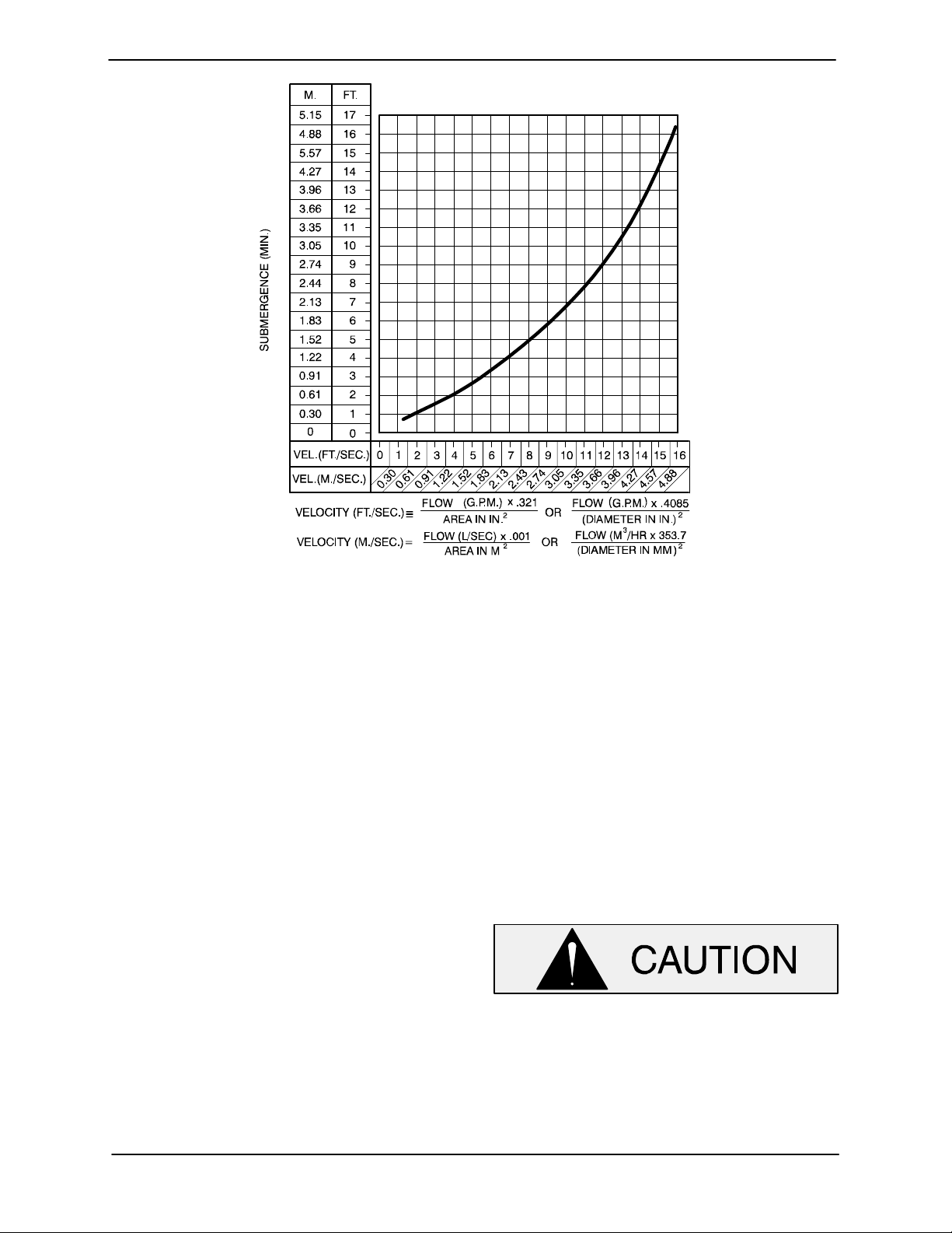
The depth of submergence of the suction line is
critical to efficient pump operation. Figure 2 shows
recommended minimum submergence vs. veloci
ty.
NOTE
The pipe submergence required may be reduced
by installing a standard pipe increaser fitting at the
end of the suction line. The larger opening size will
reduce the inlet velocity. Calculate the required
submergence using the following formula based
on the increased opening size (area or diameter).
PAGE B - 6 INSTALLATION
Page 15
SUPER T SERIES OM-07174
Figure 2. Recommended Minimum Suction Line Submergence vs. Velocity
SUBMERSIBLE TRANSDUCER
This unit is equipped with an optional Electronic
Pressure Switch (EPS) that works in conjunction
with a submersible transducer. The submersible
transducer converts pressure to an electrical sig
nal proportional to liquid level. This electrical signal
is distributed to the digital display on the EPS
through a scaling circuit which converts the electri
cal signal to “feet of water”.
When installing the submersible transducer, note
the following:
a. Handle the signal cable and transducer with
care during installation. Carefully lower the
transducer into the wet well or sump; do not
drop it to the bottom. To avoid clogging, sus
pend the transducer off the bottom.
b. Be sure to provide sufficient room in the wet
well or sump so that the transducer does not
get drawn into the suction line. To prevent this,
a flexible suction hose may be extended to lay
along the bottom of the wet well or sump. The
transducer can then be attached to the hose
above the point where it bends along the bot
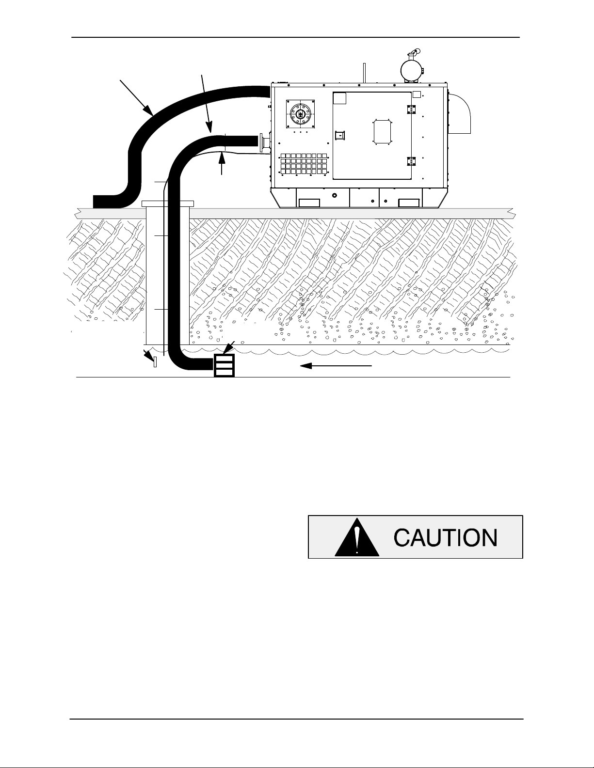
tom. See Figure 3 for a typical installation.
c. The wet well or sump must be vented to at
mosphere.
d. The EPS is scaled in feet of water column. If
the measured medium is other than 1.0 spe
cific gravity, the reading on the EPS should be
divided by the specific gravity of the mea
sured medium to obtain the actual level.
e. Thoroughly clean the transducer after each
use to prevent clogging.
Do not disassemble the transducer or
loosen the compression nut at the signal
cable entry. This will void warranty. There
are no user‐serviceable parts inside. Do
not nick or cut the jacket of the signal ca
ble; this will cause leakage and void war
ranty.
PAGE B - 7INSTALLATION
Page 16
OM-07174 SUPER T SERIES
SUCTION
DISCHARGE
LINE
LINE
SIGNAL CABLE
(ATTACH TO
SUCTION LINE)
SUBMERSIBLE
TRANSDUCER
(DOWNSTREAM
FROM SUCTION)
SUCTION
STRAINER
Figure 3. Typical Submersible Transducer Installation
DISCHARGE LINES
Siphoning
Do not terminate the discharge line at a level lower
than that of the liquid being pumped unless a
siphon breaker is used in the line. Otherwise, a si
phoning action causing damage to the pump
could result.
Valves
If a throttling valve is desired in the discharge line,
use a valve as large as the largest pipe to minimize
FLOW
friction losses. Never install a throttling valve in a
suction line.
With high discharge heads, it is recommended that
a throttling valve and a system check valve be in
stalled in the discharge line to protect the pump
from excessive shock pressure and reverse rota
tion when it is stopped.
If the application involves a high discharge
head, gradually close the discharge throt
tling valve before stopping the pump.
PAGE B - 8 INSTALLATION
Page 17
SUPER T SERIES
OPERATION - SECTION C
OPERATION
Review all SAFETY information in Section A.
OM-07174
Follow the instructions on all tags, labels and
decals attached to the pump.
Do not operate an internal combustion
engine in an explosive atmosphere.
When operating an internal combustion
engine in an enclosed area, make sure
exhaust fumes are piped to the outside.
These fumes contain carbon monoxide,
a deadly gas that is colorless, tasteless
and odorless.
This pump is designed to handle most
non‐volatile, non‐flammable liquids
containing specified entrained solids
and corrosives. Do not attempt to pump
volatile, corrosive, or flammable liquids
which may damage the pump or endan
ger personnel as a result of pump fail
ure.
Pump speed and operating condition
points must be within the continuous per
formance range shown on the perfor
mance curve on page E-1.
Make sure the pump is level. Lower jack
stands and chock the wheels, if so
equipped. Use caution when positioning
the skid‐mounted unit to prevent damage
to the fuel tank.
This pump is equipped with an automat
ic starting system, and is subject to au
tomatic restart. Keep hands and cloth
ing away from the unit to prevent injury
during automatic operation. Disconnect
the positive battery cable before per
forming any maintenance. Failure to do
so may result in serious personal injury.
Consult the engine operations manual before at
tempting to start the unit.
Consult the manual accompanying the engine
control box and start the pump.
PRIMING
Install the pump and piping as described in IN
STALLATION. Make sure that the piping connec
tions are tight, and that the pump is securely
mounted. Check that the pump is properly lubri
cated (see LUBRICATION in MAINTENANCE
AND REPAIR).
This pump is self‐priming, but the pump should
never be operated unless there is liquid in the
pump casing.
STARTING
Check the fuel level and oil levels in the engine, air
compressor, pump bearings and seal housing.
Never operate this pump unless there is
liquid in the pump casing. The pump will
Make sure the pump is level. Lower the jack stands
and chock the wheels, if so equipped.
OPERATION PAGE C - 1
not prime when dry. Extended operation of
a dry pump will destroy the seal assembly.
Page 18
OM-07174 SUPER T SERIES
Add liquid to the pump casing when:
1. The pump is being put into service for the
first time.
2. The pump has not been used for a consider
able length of time.
3. The liquid in the pump casing has evapo
rated.
Once the pump casing has been filled, the pump
will prime and reprime as necessary.
After filling the pump casing, reinstall
and tighten the fill plug. Do not attempt
to operate the pump unless all connect
ing piping is securely installed. Other
wise, liquid in the pump forced out un
der pressure could cause injury to per
sonnel.
To fill the pump, remove the pump casing fill cover
or fill plug in the top of the casing, and add clean
liquid until the casing is filled. Replace the fill cover
or fill plug before operating the pump.
S Three switches on front panel for all adjust
ments
S Battery level indicator on LCD screen to alert
operator of low battery condition
S Microprocessor Control
S Error display to alert user of errors in calibra
tion
Functional Description
Front Panel Controls/Displays
1. The LCD screen displays level information,
A and B setpoint off/on levels, Horn delay,
and calibration information.
Typical Messages on the display:
a) EEP bAd... Eeprom memory is not cor
rect, user must recalibrate
unit.
b) USr CAL... User calibrate mode, i.e.,
user wants to calibrate unit.
c) SEt a.oF... A OFF setpoint, units of lev
el.
d) SEt a.on... A ON setpoint, units of level.
NOTE
If the suction or discharge piping is open, a hose
can be used to fill the casing through the piping.
OPTIONAL EPS CONTROL
Features
The optional EPS Control is equipped with a
12VDC Electronic Pressure Switch which includes
the following features:
S 3 Output Relays: 1. A output, delayed
2. B output, no delay
3. Horn output, no delay
S 3 Inputs: 1. Horn silence
2, Pressure transducer
3. Low Temp Thermostat
S LCD screen with backlight for function moni
toring
S Bright LEDs to indicate output status and dis
play modes
e) SEt b.oF... B OFF setpoint, units of lev
el.
f) SEt b.on... B ON setpoint, units of level.
g) Hrn dLy... Horn on, A output delay
time, 5-30 seconds, in
5‐second increments.
h) LO BAT... Indicator, shows battery
voltage level is below
12VDC.
i) Lo tpt... Shows status of Low Tem
perature Thermostat con
tacts.
2. LEDs:
a) When the green LED is lighted, the unit is
showing level on the LCD display.
b) When the A output LED is lighted, the A
output relay is closed.
c) When the B output LED is lighted, the B
output relay is closed
NOTE
LED's and all segments of the display are lighted
OPERATIONPAGE C - 2
Page 19
SUPER T SERIES
OM-07174
upon connection of power as a lamp test feature.
However, no relay outputs are closed during test.
3. Switches:
a) The switch functions as a “round rob
in” type switch. Pressing this switch will
cause the unit to show the next selection
in the order listed above.
b) The switch functions to decrease the
selection showing. This switch can be
used to decrease the smallest digit by
“bumping” the switch, or to continuously
decrease the digit by pressing and hold
ing for at least one second and releasing
when desired setting is reached.
c. The switch functions to increase the
selection showing. This switch can be
used to increase the smallest digit by
“bumping” the switch, or to continuously
increase the digit by pressing and hold
ing for at least one second and releasing
when desired setting is reached.
Liquid level adjustment of the Electronic Pressure
Switch is accomplished using the three buttons on
the control. For EPS functions and level adjust
ment, refer to the following instructions.
EPS Functions
When the pressure decreases to a level equal
to or less than the “A.of” setpoint, A output con
tacts will open in approximately one second.
If an optional Low Temperature Thermostat is
connected to the unit and the thermostat con
tacts close, the unit displays “lo tpt” on the dis
play. In approximately 1 second, the Horn out
put contacts close, then after the “Hrn dLy”
time, A output contacts close. A output con
tacts will remain closed as long as Low Tem
perature Thermostat contacts are closed.
When the Low Temperature Contacts open, A
output contact will open only if the level is
equal to or less than the “A.off” setpoint.
As long a the Low Temperature Thermostat
contacts are closed, the display will show “lo
tpt” unless switch is pressed to display
some other information. Level is not viewable
until the Low Temperature Thermostat con
tacts open.
The user may wish to check Setpoints Off/On
and Horn output/A output delay times. “Bump
ing” the switch will display all of the informa
tion desired.
NOTE
One second delays in contact opening/closing is a
result of time sampling of the pressure signal to fil
ter false signals that could cause “nuisance” trip
ping of the contacts.
Actual functions of the control occur as follows:
Power is applied to the unit.
Unit performs display test for approximately 4
seconds.
When the pressure level showing is equal to or
greater than the “A.on” setpoint, the Horn out
put contacts will close in approximately 1 sec
ond and a delay, equal to the “Hrn dLy” time,
will occur before the A output contacts close.
When the level showing is equal to or greater
than the “B.on” setpoint, the B output contacts
will close in approximately 1 second.
When the pressure decreases to a level equal
to or less than the “B.of” setpoint, B output
contacts will open in approximately one sec
ond.
OPERATION PAGE C - 3
If the “Hrn dLy” is changed during the actual A out
put delay cycle, the current cycle is not changed;
the change becomes effective on the next A output
delay cycle.
Use caution to ensure that the “‐‐.on” set
point (i.e. “A.on”) is not adjusted to a level
less than the corresponding “‐‐.of” set
point (i.e. “A.of”). Improper adjustment of
the off/on setpoints will render the unit non‐
functional, resulting in flooding.
NOTE
Page 20
OM-07174 SUPER T SERIES
EPS Calibration
NOTE
Zero offset and span adjustments are only neces
sary to calibrate a new unit, or when replacing the
transducer. Once calibrated, “ON” and “OFF” set
points will be stored in the unit's memory. Liquid
level adjustments will be used whenever “ON” and
“OFF” liquid levels must be reset.
There are two reasons for the user to calibrate the
unit. When power is applied, the unit confirms set
points and other calibration information for validity.
If the setpoints are not valid, the LCD screen shows
“EEP bAd” and the unit must be recalibrated. Also,
if the unit is moved, or some other external change
takes place, the unit must be recalibrated.
Zero Adjustment
Zero adjustment tells the unit when the transducer
is exposed to zero water (atmospheric) pressure.
When recalibration is desired, hold the transducer
in hand and apply power to the unit. The LCD
screen will display “Level ABC”. Press and hold
for 5 seconds. The LCD screen displays “Input?
External XDUCR”. Perform the following calibration
procedures.
Press 3 times and the LCD screen will display
“Calibrate Zro”. Press or until a character or
number on the display changes.
Level Adjustment
Level adjustment tells the unit when to turn the
pump on and off. To set:
From “Level ABC” display, press once and
“Pump Setpt A On” will display. Press to in
crease or to decrease to the desired level at
which the pump turns on. Press to advance to
“Pump Setpt A Off”. Press to increase or to
decrease to the desired level at which the pump
turns off.
Press again to advance to “Pump Setpt B On”. If
“B” is to be used, repeat the procedure described
above for adjusting level “A”.
Horn Delay
The horn delay is pre‐set from the factory through
the engine control panel, therefore this function is
not utilized through the EPS.
ROUTINE OPERATION
Adjust the engine speed to achieve the desired
output. Do not exceed the factory set engine speed
and system operating pressure. Do not operate
below the recommended operating speed (if appli
cable).
Press to accept the entry and advance to “Cali
brate Span”.
Span Adjustment
Span adjustment calibrates the unit to a known wa
ter pressure (depth). To set:
Submerge the transducer to an exact known
depth. At “Calibrate Span”, the span setting in the
unit's memory will display. Press to increase or
to decrease the value unitl the LCD screen dis
play equals the actual known depth of the trans
ducer.
Never tamper with the governor to gain
more power. The governor establishes
safe operating limits that should not be
exceeded. Refer to the Performance
Curve in Section E for the maximum
continuous operating speed for this
pump.
A Gorman‐Rupp automatic air release valve may
be installed in a bypass line, or the bypass line may
be left open.
OPERATIONPAGE C - 4
Page 21
SUPER T SERIES
A manual shut‐off valve should not be
installed in any bypass line. A manual
shut‐off valve may inadvertently be left
closed during operation. A pump which
has lost prime may continue to operate
without reaching prime, causing dan
gerous overheating and possible explo
sive rupture of the pump casing. Per
sonnel could be severely injured.
Lines With a Bypass
OM-07174
OPERATION IN EXTREME HEAT
The safety shutdown system will automatically
stop the unit if engine operating temperature ex
ceeds design limits. If engine over‐temperature
shutdown occurs, allow the unit to cool before re
starting.
If engine overheating continues, check the engine
lubricant level and viscosity. Consult the engine
operation manual for the recommended lubricant
for operation in extreme heat.
If the unit is being operated in the automatic mode,
adjust the liquid level device(s) to allow shorter run
and longer cooling periods, if possible.
OPERATIONAL CHECKS
If a Gorman‐Rupp Automatic Air Release Valve has
been installed, the valve will automatically open to
allow the pump to prime, and automatically close
after priming is complete (see INSTALLATION for
Air Release Valve operation).
If the bypass line is open, air from the suction line
will be discharged through the bypass line back to
the wet well during the priming cycle. Liquid will
then continue to circulate through the bypass line
while the pump is in operation.
Lines Without a Bypass
Open all valves in the discharge line and start the
engine. Priming is indicated by a positive reading
on the discharge pressure gauge or by a quieter
operation. The pump may not prime immediately
because the suction line must first fill with liquid. If
the pump fails to prime within five minutes, stop it
and check the suction line for leaks.
Leakage
Once the pump is fully primed, no leakage should
be visible at pump mating surfaces, or at pump
connections or fittings. Keep all line connections
and fittings tight to maintain maximum pump effi
ciency.
Pump Vacuum Check
Read the vacuum gauge with the pump primed
and at operation speed. Shut off the pump. The
vacuum gauge reading will immediately drop pro
portionate to static suction lift, and should then sta
bilize. If the vacuum reading falls off rapidly after
stabilization, an air leak exists. Before checking for
the source of the leak, check the point of installa
tion of the vacuum gauge.
Liquid Temperature And Overheating
The maximum liquid temperature for this pump is
160_F (71_C). Do not apply it at a higher operating
temperature.
After the pump has been primed, partially close the
discharge line throttling valve in order to fill the line
slowly and guard against excessive shock pres
sure which could damage pipe ends, gaskets,
sprinkler heads, and any other fixtures connected
to the line. When the discharge line is completely
filled, adjust the throttling valve to the required flow
rate.
OPERATION PAGE C - 5
Overheating can occur if operated with the valves
in the suction or discharge lines closed. Operating
against closed valves could bring the liquid to a
boil, build pressure, and cause the pump to rup
ture or explode. If overheating occurs, stop the
pump immediately and allow it to completely cool
before servicing it. Approach any over‐heated
pump cautiously.
Page 22
OM-07174 SUPER T SERIES
Automatic Stopping
In the automatic mode, the pump will stop when
the liquid in the wet well or sump lowers and acti
Allow an over‐heated pump to com
pletely cool before servicing. Do not re
move plates, covers, gauges, or fittings
vates the “Off” liquid level device(s). The pump will
restart automatically when the liquid rises and acti
vates the “On” liquid level device(s).
from an overheated pump. Liquid within
the pump can reach boiling tempera
Safety Shutdown System
tures, and vapor pressure within the
pump can cause parts being disen
gaged to be ejected with great force. Af
ter the pump cools, drain the liquid from
The unit is equipped with a safety system to auto
matically shut down the engine under certain con
ditions.
the pump by removing the casing drain
plug. Use caution when removing the
plug to prevent injury to personnel from
hot liquid.
Displays on the control panel will indicate which of
the safety features has caused the engine to shut
down.
Strainer Check
Check the strainer regularly, and clean it as neces
sary. The strainer should also be checked if pump
flow rate begins to drop. Monitor and record the
vacuum suction gauge readings regularly to detect
strainer blockage.
Never introduce air or steam pressure into the
pump casing or piping to remove a blockage. This
could result in personal injury or damage to the
equipment. If backflushing is absolutely neces
sary, liquid pressure must be limited to 50% of the
maximum permissible operating pressure shown
on the pump performance curve.
STOPPING
Manual Stopping
Should any of the safety features cause the engine
to shut down, the cause must be determined and
corrected before putting the unit back into service.
All safety shutdown features are pre‐set at the fac
tory for optimum performance and safety; do not
attempt to adjust these settings.
Never disconnect any of the safety shut
down features; this will void the warran
ty and could result in serious damage to
the unit and/or injury to personnel. Safe
ty shutdown features are pre‐set at the
factory; do not attempt to adjust any of
the settings. Determine the cause of
shutdown before putting the unit back
into service. Consult the factory for ad
ditional information.
In the manual mode, reduce the throttle speed
slowly, and allow the engine to idle briefly before
turning the keyswitch to `OFF'.
If the application involves a high discharge
head, gradually close the discharge
throttling valve before stopping the pump.
PERIODIC CHECKS
Seal Cavity and Bearing Lubrication
Both the seal and bearing cavities were fully lubri
cated at the factory. Check the lubrication levels
before startup, and regularly thereafter as indi
cated in Section E, Maintenance and Repair.
When lubrication is required, use only SAE No. 30
non‐detergent oil.
OPERATIONPAGE C - 6
Page 23

SUPER T SERIES
OM-07174
Bearing Temperature Check
Bearings normally run at higher than ambient tem
peratures because of heat generated by friction.
Temperatures up to 160
normal for bearings, and they can operate safely to
at least 180_F (82_C).
Checking bearing temperatures by hand is inaccu
rate. Bearing temperatures can be measured ac
curately by placing a contact‐type thermometer
against the housing. Record this temperature for
future reference.
A sudden increase in bearing temperatures is a
warning that the bearings are at the point of failing
to operate properly. Make certain that the bearing
lubricant is of the proper viscosity and at the cor
rect level (see LUBRICATION in Section E, Main
tenance and Repair). Bearing overheating can
also be caused by shaft misalignment and/or ex
cessive vibration.
When pumps are first started, the bearings may
seem to run at temperatures above normal. Con
tinued operation should bring the temperatures
down to normal levels.
Engine Fuel Filter
Consult the manual accompanying the engine,
and change the fuel filter periodically as indicated.
If operated under extremely dusty and/or humid
_
F (71_C) are considered
conditions, change the filter more frequently. Irreg
ular performance and loss of power usually indi
cate a dirty fuel filter.
Engine Oil
The engine was lubricated for test at the factory.
However, always check the lubrication level before
startup.
Consult the manual accompanying the engine,
and change the oil filter periodically as indicated. If
operated under extremely dusty conditions,
change the filter more frequently.
COLD WEATHER PRESERVATION
In below freezing conditions, drain the pump to
prevent damage from freezing. Also, clean out any
solids by flushing with a hose. Operate the pump
for approximately one minute; this will remove any
remaining liquid that could freeze the pump rotat
ing parts. If the pump will be idle for more than a
few hours, or if it has been pumping liquids con
taining a large amount of solids, drain the pump,
and flush it thoroughly with clean water. To prevent
large solids from clogging the drain port and pre
venting the pump from completely draining, insert
a rod or stiff wire in the drain port, and agitate the
liquid during the draining process. Clean out any
remaining solids by flushing with a hose.
OPERATION PAGE C - 7
Page 24
TROUBLESHOOTING - SECTION D
OM-07174SUPER T SERIES
Review all SAFETY information in Section A.
Before attempting to open or service the
pump:
1. Familiarize yourself with this man
ual.
2. Shut down the engine, remove the
key and disconnect the positive
battery cable to ensure that the
pump will remain inoperative.
3. Allow the pump to completely cool
if overheated.
4. Check the temperature before
opening any covers, plates, or
plugs.
TROUBLE POSSIBLE CAUSE PROBABLE REMEDY
PUMP FAILS TO PRIME Not enough liquid in casing.
5. Close the suction and discharge
valves.
6. Vent the pump slowly and cau
tiously.
7. Drain the pump.
This pump is equipped with an automat
ic starting system, and is subject to au
tomatic restart. Keep hands and cloth
ing away from the unit to prevent injury
during automatic operation. Disconnect
the positive battery cable before per
forming any maintenance. Failure to do
so may result in serious personal injury.
Add liquid to casing. See PRIMING.
PUMP STOPS OR FAILS
TO DELIVER RATED
FLOW OR PRESSURE
Suction check valve contaminated or
damaged.
Air leak in suction line.
Lining of suction hose collapsed.
Leaking or worn seal or pump gas
ket.
Suction lift or discharge head too
high.
Strainer clogged.
Air leak in suction line.
Lining of suction hose collapsed.
Leaking or worn seal or pump gas
ket.
Strainer clogged.
Clean or replace check valve.
Correct leak.
Replace suction hose.
Check pump vacuum. Replace leak
ing or worn seal or gasket.
Check piping installation and install
bypass line if needed. See INSTAL
LATION.
Check strainer and clean if neces
sary.
Correct leak.
Replace suction hose.
Check pump vacuum. Replace
leaking or worn seal or gasket.
Check strainer and clean if neces
sary.
Suction intake not submerged at
proper level or sump too small.
TROUBLESHOOTING PAGE D - 1
Check installation and correct sub
mergence as needed.
Page 25

OM-07174 SUPER T SERIES
TROUBLE POSSIBLE CAUSE PROBABLE REMEDY
PUMP STOPS OR FAILS
TO DELIVER RATED
FLOW OR PRESSURE
(cont.)
PUMP REQUIRES TOO
MUCH POWER
Impeller or other wearing parts
worn or damaged.
Impeller clogged.
Discharge head too high.
Suction lift too high.
Pump speed too slow.
EPS limit switches set improperly or
submersible transducer clogged.
Pump speed too high.
Discharge head too low.
Liquid solution too thick.
Bearing(s) frozen.
Replace worn or damaged parts.
Check that impeller is properly cen
tered and rotates freely.
Free impeller of debris.
Install bypass line.
Measure lift w/vacuum gauge. Re
duce lift and/or friction losses in
suction line.
Check engine output; consult en
gine operation manual.
Check EPS limit settings; check and
clean submersible transducer.
Check engine output.
Adjust discharge valve.
Dilute if possible.
Disassemble pump and check
bearing(s).
PUMP CLOGS
FREQUENTLY
EXCESSIVE NOISE Cavitation in pump.
BEARINGS RUN TOO
HOT
Discharge flow too slow.
Suction check valve or foot valve
clogged or binding.
Liquid solution too thick.
Pumping entrained air.
Pump or drive not securely
mounted.
Impeller clogged or damaged.
Bearing temperature is high, but
within limits.
Open discharge valve fully to in
crease flow rate, and run engine at
maximum governed speed.
Clean valve.
Dilute if possible.
Reduce suction lift and/or friction
losses in suction line. Record vacu
um and pressure gauge readings
and consult local representative or
factory.
Locate and eliminate source of air
bubble.
Secure mounting hardware.
Clean out debris; replace damaged
parts.
Check bearing temperature regular
ly to monitor any increase.
Low or incorrect lubricant.
Suction and discharge lines not
properly supported.
Drive misaligned.
Check for proper type and level of
lubricant.
Check piping installation for proper
support.
Align drive properly.
TROUBLESHOOTINGPAGE D - 2
Page 26
OM-07174SUPER T SERIES
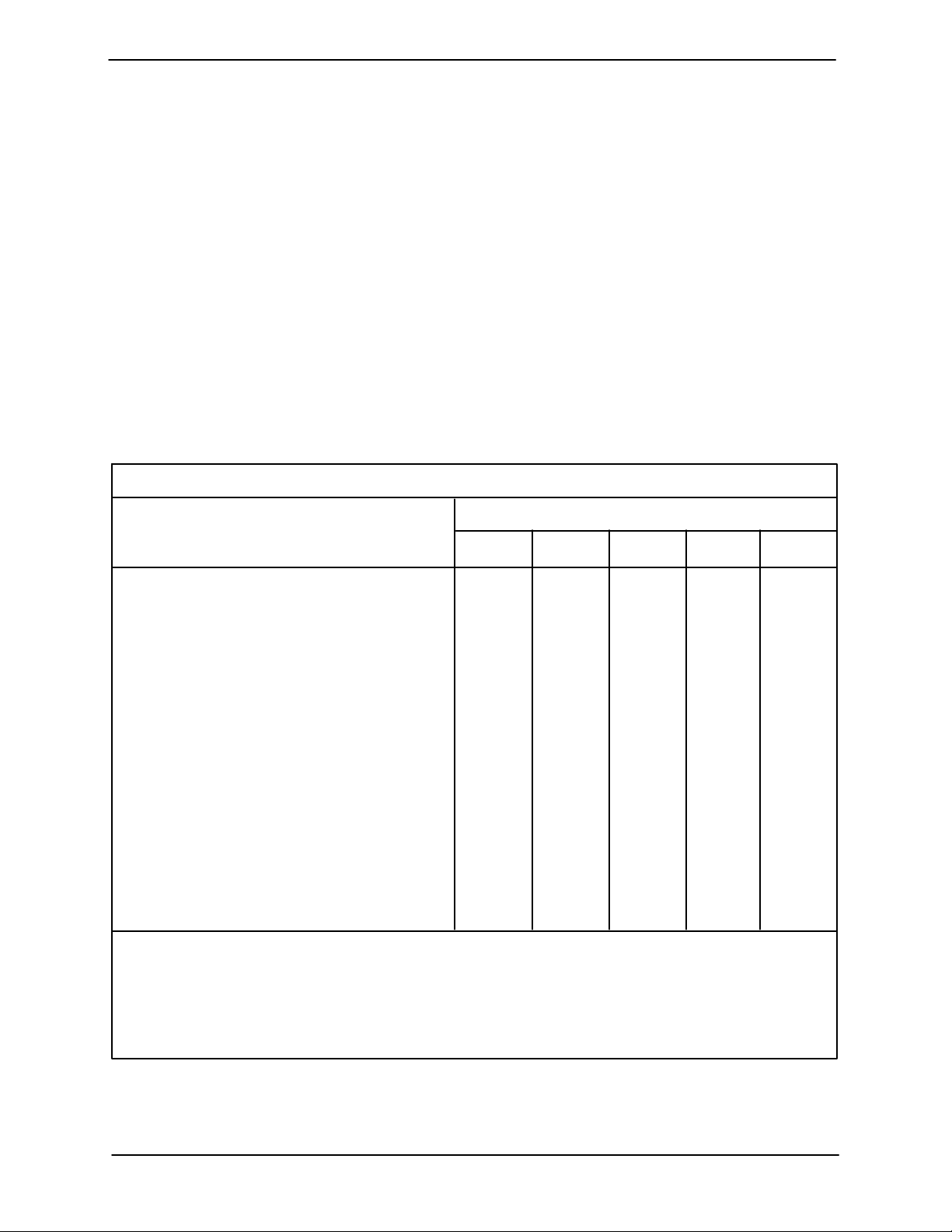
PREVENTIVE MAINTENANCE
Since pump applications are seldom identical, and
pump wear is directly affected by such things as
the abrasive qualities, pressure and temperature
of the liquid being pumped, this section is intended
only to provide general recommendations and
practices for preventive maintenance. Regardless
of the application however, following a routine pre
ventive maintenance schedule will help assure
trouble‐free performance and long life from your
Gorman‐Rupp pump. For specific questions con
cerning your application, contact your Gorman‐
Rupp distributor or the Gorman‐Rupp Company.
Record keeping is an essential component of a
good preventive maintenance program. Changes
in suction and discharge gauge readings (if so
equipped) between regularly scheduled inspec
tions can indicate problems that can be corrected
before system damage or catastrophic failure oc
curs. The appearance of wearing parts should also
be documented at each inspection for comparison
as well. Also, if records indicate that a certain part
(such as the seal) fails at approximately the same
duty cycle, the part can be checked and replaced
before failure occurs, reducing unscheduled down
time.
For new applications, a first inspection of wearing
parts at 250 hours will give insight into the wear rate
for your particular application. Subsequent inspec
tions should be performed at the intervals shown
on the chart below. Critical applications should be
inspected more frequently.
Preventive Maintenance Schedule
Service Interval*
Item
General Condition (Temperature, Unusual
Noises or Vibrations, Cracks, Leaks,
Loose Hardware, Etc.) I
Pump Performance (Gauges, Speed, Flow) I
Bearing Lubrication I R
Seal Lubrication (And Packing Adjustment,
If So Equipped) I R
V‐Belts (If So Equipped) I
Air Release Valve Plunger Rod (If So Equipped) I C
Front Impeller Clearance (Wear Plate) I
Rear Impeller Clearance (Seal Plate) I
Check Valve I
Pressure Relief Valve (If So Equipped) C
Pump and Driver Alignment I
Shaft Deflection I
Bearings I
Bearing Housing I
Piping I
Driver Lubrication - See Mfgr's Literature
Daily Weekly Monthly Semi‐
Annually
Annually
Legend:
I = Inspect, Clean, Adjust, Repair or Replace as Necessary
C = Clean
R = Replace
* Service interval based on an intermittant duty cycle equal to approximately 4000 hours annually.
Adjust schedule as required for lower or higher duty cycles or extreme operating conditions.
TROUBLESHOOTING PAGE D - 3
Page 27
SUPER T SERIES OM-07174
PUMP MAINTENANCE AND REPAIR ‐ SECTION E
MAINTENANCE AND REPAIR OF THE WEARING PARTS OF THE PUMP WILL MAINTAIN PEAK
OPERATING PERFORMANCE.
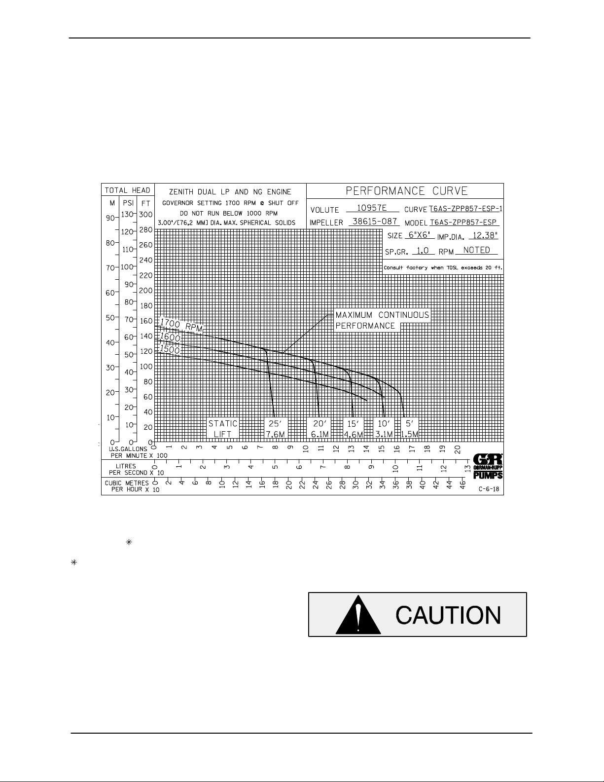
STANDARD PERFORMANCE FOR PUMP MODEL T6A60S-ZPP857-ESP
Based on 70_F (21_C) clear water at sea level with
minimum suction lift. Since pump installations are
seldom identical, your performance may be differ
ent due to such factors as viscosity, specific gravity,
elevation, temperature, and impeller trim.
Contact the Gorman‐Rupp Company to verify per
formance or part numbers.
Pump speed and operating condition
If your pump serial number is followed by an “N”,
your pump is NOT a standard production model.
MAINTENANCE & REPAIR PAGE E - 1
points must be within the continuous per
formance range shown on the curve.
Page 28
PARTS PAGE
46
47
45
48
SUPER T SERIESOM-07174
ILLUSTRATION
49
50
5251
17
16
15
14
13
15
12
18
DETAIL A
38
34
19
12
20
61
12
19
21
18
15
11
12
30 29 62
55
55
60
5
7
8
6
4
63
64
65
66
67
68 69
70
715659
53
54
5655
5659
58
57
78
A
22
23
24
10
9
272625 4
37
3
31
36
35
5 4
7 8
32
33
33
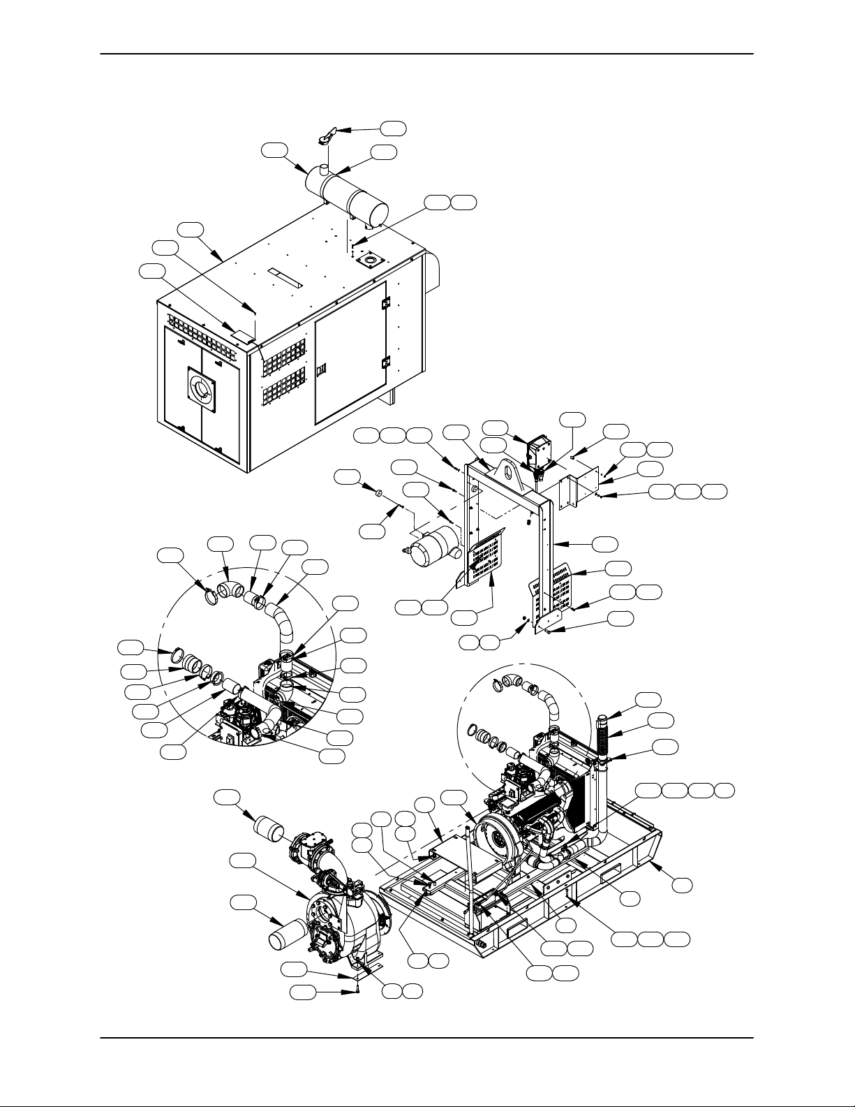
Figure 1. Pump Model T6A60S-ZPP857-ESP
MAINTENANCE & REPAIRPAGE E - 2
2
1
28 29 30
Page 29
SUPER T SERIES OM-07174
PARTS LIST
Pump Model T6A60S-ZPP857-ESP
(From S/N 1703506 Up)
If your pump serial number is followed by an “N”, your pump is NOT a standard production model. Contact
the Gorman‐Rupp Company to verify part numbers.
ITEM
PART NAME PART
NO.
NUMBER
QTY ITEM
NO.
PART NAME PART
NUMBER
QTY
1 BASE WELDMENT 41565-603 24150 1
2 SUB BASE ASSY 41531-576 24150 1
3 COMPRESSION MOUNT 24631-104 6
4 LOCK WASHER J08 15991 24
5 HEX HEAD CAP SCREW B0805 15991 18
6 HEX HEAD CAP SCREW B1006 15991 4
7 LOCK WASHER J10 15991 14
8 HEX NUT D10 15991 14
9 PUMP MNTG BRCKT ASSY 41581-094 24150 1
10 ZENITH ZPP857 ENGINE 29267-008 1
11 THERMO HOSE X 36" LG 18533-173 1
12 TBOLT CLAMP 3.5 IN 26518-164 4
13 EXHAUST TUBING 31417-076 15210 1
14 AIR INTAKE REDCG INSRT 29284-043 1
15 T‐BOLT CLAMP 4 IN 26518-165 3
16 SLEEVE 26413-002 1
17 HOSE CLAMP 26518-678 1
18 ELBOW, REDUCING, 90° 29284-040 2
19 AIR INTAKE PIPE 31417-066 15210 2
20 THERMO HOSE X 18" LG 18533-173 1
21 T‐BOLT CLAMP 3 IN 26518-163 2
22 EXHAUST CLAMP 29334-287 1
23 FLEX CONNECTOR 31782-004 1
24 MUFFLER CLAMP 3.50 S2227 1
25 HEX HEAD CAP SCREW B0806 15991 6
26 HEX NUT D08 15991 6
27 FLAT WASHER K08 15991 6
28 HEX HEAD CAP SCREW B0505 15991 10
29 LOCK WASHER J05 15991 23
30 FLAT WASHER K05 15991 23
31 1/0 POS. CABLE ASSY 47311-112 1
32 1/0 NEG. CABLE ASSY 47311-142 1
33 SQUARE HEAD BOLT A0506 15991 2
34 PUMP END ASSEMBLY 46186-187 1
35 HEX HEAD CAP SCREW B1010 15991 4
36 PUMP SPACER 33246-058 15120 2
37 PIPE NIPPLE T9654 15079 1
38 PIPE NIPPLE T9636 15079 1
39 CLOSE PIPE NIPPLE T16 15070 3
40 PIPE ELBOW R16 15070 1
41 PIPE TEE U16 11990 1
42 REDUCER PIPE BUSHING AP1604 15070 1
43 PIPE PLUG P04 15070 1
44 NAT GAS & LPG HOSE 29332-306 1
45 ENCLOSURE ASSY 42164-051 1
46 SOLAR CHARGER 27558-013 1
47 TAP SCREW #10 X 3/4 21281-446 6
48 MUFFLER 3" 29334-105 1
49 WEATHER CAP S2021 1
50 10" DIA MOUNTING BRKT 29334-288 2
51 HEX HEAD CAP SCREW B0505 15991 4
52 LOCK WASHER J05 15991 4
53 HOIST BAIL ASSY 44713-067 24150 1
54 HEAT SHIELD ASSY 42381-145 1
55 HEX HEAD CAP SCREW B0605 15991 20
56 LOCK WASHER J06 15991 20
57 HEX HEAD CAP SCREW B1006-1/2 15991 6
58 HEAT SHIELD 34167-015 15120 1
59 HEX NUT D06 15991 6
60 HEX HEAD CAP SCREW B0508 15991 2
61 SPACER 31141-037 13000 2
62 HEX NUT D05 15991 2
63 GASKET 33311-060 19460 1
64 CONTROL PANEL 29196-071 1
65 TRNSDCR HARNESS 29196-076 1
66 INTERFACE HARNESS 29196-075 1
67 STUD MOUNT 24631-014 4
68 HEX NUT D04 15991 4
69 LOCK WASHER J04 15991 4
70 MOUNTING BRACKET 34512-065 13000 1
71 FLAT WASHER K06 15991 4
72 MOUNTING ASS'Y 41881-788 1
73 THREADED INSERT 21769-160 8
74 HEX HEAD CAP SCREW B0504 15991 11
75 BATTERY BOX ASSY 42432-005 1
76 OPW ADAPTER 1 1/4 26531-404 1
77 REDUCER PIPE BUSHING AP2016 11999 2
78 STREET ELBOW RS16 11999 1
79 HOSE FITTING 26523-394 3
80 HOSE CLAMP 26518-666 4
81 HOSE 1" ID X 26" LG 18513-045 1
82 SUCTION TRANSDUCER 27780-988 1
83 PIPE ELBOW R16 15079 1
84 PIPE NIPPLE T1608 15079 1
85 REDUCER PIPE BUSHING AP2016 17040 1
86 CLOSE PIPE NIPPLE T16 15079 1
87 BALL VALVE 26631-025 1
88 HOSE 1" ID X 58" LG 18513-045 1
89 PIPE PLUG P20 10009 1
90 PIPE PLUG P32 14990 3
91 DSCHRG TRANSDUCER 27780-989 1
92 HOSE CLAMP 26518-641 2
93 HOSE .38 I.D. X 28" LG 18513-054 1
94 MALE HOSE END 26525-020 2
95 PIPE PLUG P08 15079 2
96 HOSE .38 I.D. X 24" LG 18513-054 1
NOT SHOWN:
ENG OPERATION DECAL 38816-347 1
ENGINE START‐UP TAG 38816-269 1
CAUTION DECAL 38816-169 1
WARNING DECAL 2613FE 1
PUMP DRAIN LABEL 38816-320 1
WARNING DECAL 38817-101 2
AIR RLSE DRAIN LABEL 38816-333 1
WARNING DECAL 38816-203 4
FOAM TAPE 279" LG 18668-003 1
RADIATOR DRAIN LABEL 38816-322 1
OIL DRAIN LABEL 38816-323 1
WARNING DECAL 38816-345 2
INSTRUCTION DECAL 38818-144 1
EXHAUST BLANKET 46241-018 1
EXHST INSULTN WRAP 29330-441 2
9" SNAP STRAP 29330-443 8
18" SNAP STRAP 29330-444 4
MAINTENANCE & REPAIR PAGE E - 3
Page 30
ILLUSTRATION
SUPER T SERIESOM-07174
43
42
39
79 77
80
88
80
868779
85 84 83
82
44
39
41
40
39
FUEL LINE CONNECTION
90
89
91
92
93
65
66
94
90
47
47
46
95
94
46
96
90
1
92
72
73
74
30
29
81
76
80
7778
7980
75
Figure 2. Pump Model T6A60S-ZPP857-ESP (cont'd)
MAINTENANCE & REPAIRPAGE E - 4
Page 31
SUPER T SERIES OM-07174
PARTS LIST
Pump Model T6A60S-ZPP857-ESP
ITEM
PART NAME PART
NO.
NUMBER
QTY ITEM
NO.
PART NAME PART
NUMBER
QTY
1 BASE WELDMENT 41565-603 24150 1
2 SUB BASE ASSY 41531-576 24150 1
3 COMPRESSION MOUNT 24631-104 6
4 LOCK WASHER J08 15991 24
5 HEX HEAD CAP SCREW B0805 15991 18
6 HEX HEAD CAP SCREW B1006 15991 4
7 LOCK WASHER J10 15991 14
8 HEX NUT D10 15991 14
9 PUMP MNTG BRCKT ASSY 41581-094 24150 1
10 ZENITH ZPP857 ENGINE 29267-008 1
11 THERMO HOSE X 36" LG 18533-173 1
12 TBOLT CLAMP 3.5 IN 26518-164 4
13 EXHAUST TUBING 31417-076 15210 1
14 AIR INTAKE REDCG INSRT 29284-043 1
15 T‐BOLT CLAMP 4 IN 26518-165 3
16 SLEEVE 26413-002 1
17 HOSE CLAMP 26518-678 1
18 ELBOW, REDUCING, 90° 29284-040 2
19 AIR INTAKE PIPE 31417-066 15210 2
20 THERMO HOSE X 18" LG 18533-173 1
21 T‐BOLT CLAMP 3 IN 26518-163 2
22 EXHAUST CLAMP 29334-287 1
23 FLEX CONNECTOR 31782-004 1
24 MUFFLER CLAMP 3.50 S2227 1
25 HEX HEAD CAP SCREW B0806 15991 6
26 HEX NUT D08 15991 6
27 FLAT WASHER K08 15991 6
28 HEX HEAD CAP SCREW B0505 15991 10
29 LOCK WASHER J05 15991 23
30 FLAT WASHER K05 15991 23
31 1/0 POS. CABLE ASSY 47311-112 1
32 1/0 NEG. CABLE ASSY 47311-142 1
33 SQUARE HEAD BOLT A0506 15991 2
34 PUMP END ASSEMBLY 46186-187 1
35 HEX HEAD CAP SCREW B1010 15991 4
36 PUMP SPACER 33246-058 15120 2
37 PIPE NIPPLE T9654 15079 1
38 PIPE NIPPLE T9636 15079 1
39 CLOSE PIPE NIPPLE T16 15070 3
40 PIPE ELBOW R16 15070 1
41 PIPE TEE U16 11990 1
42 REDUCER PIPE BUSHING AP1604 15070 1
43 PIPE PLUG P04 15070 1
44 NAT GAS & LPG HOSE 29332-306 1
45 ENCLOSURE ASSY 42164-051 1
46 SOLAR CHARGER 27558-013 1
47 TAP SCREW #10 X 3/4 21281-446 6
48 MUFFLER 3" 29334-105 1
49 WEATHER CAP S2021 1
50 10" DIA MOUNTING BRKT 29334-288 2
51 HEX HEAD CAP SCREW B0505 15991 4
52 LOCK WASHER J05 15991 4
53 HOIST BAIL ASSY 44713-067 24150 1
54 HEAT SHIELD ASSY 42381-145 1
55 HEX HEAD CAP SCREW B0605 15991 20
56 LOCK WASHER J06 15991 20
57 HEX HEAD CAP SCREW B1006-1/2 15991 6
58 HEAT SHIELD 34167-015 15120 1
59 HEX NUT D06 15991 6
60 HEX HEAD CAP SCREW B0508 15991 2
61 SPACER 31141-037 13000 2
62 HEX NUT D05 15991 2
63 GASKET 33311-060 19460 1
64 CONTROL PANEL 29196-071 1
65 TRNSDCR HARNESS 29196-076 1
66 INTERFACE HARNESS 29196-075 1
67 STUD MOUNT 24631-014 4
68 HEX NUT D04 15991 4
69 LOCK WASHER J04 15991 4
70 MOUNTING BRACKET 34512-065 13000 1
71 FLAT WASHER K06 15991 4
72 MOUNTING ASS'Y 41881-788 1
73 THREADED INSERT 21769-160 8
74 HEX HEAD CAP SCREW B0504 15991 11
75 BATTERY BOX ASSY 42432-005 1
76 OPW ADAPTER 1 1/4 26531-404 1
77 REDUCER PIPE BUSHING AP2016 11999 2
78 STREET ELBOW RS16 11999 1
79 HOSE FITTING 26523-394 3
80 HOSE CLAMP 26518-666 4
81 HOSE 1" ID X 26" LG 18513-045 1
82 SUCTION TRANSDUCER 27780-988 1
83 PIPE ELBOW R16 15079 1
84 PIPE NIPPLE T1608 15079 1
85 REDUCER PIPE BUSHING AP2016 17040 1
86 CLOSE PIPE NIPPLE T16 15079 1
87 BALL VALVE 26631-025 1
88 HOSE 1" ID X 58" LG 18513-045 1
89 PIPE PLUG P20 10009 1
90 PIPE PLUG P32 14990 3
91 DSCHRG TRANSDUCER 27780-989 1
92 HOSE CLAMP 26518-641 2
93 HOSE .38 I.D. X 28" LG 18513-054 1
94 MALE HOSE END 26525-020 2
95 PIPE PLUG P08 15079 2
96 HOSE .38 I.D. X 24" LG 18513-054 1
NOT SHOWN:
ENG OPERATION DECAL 38816-347 1
ENGINE START‐UP TAG 38816-269 1
CAUTION DECAL 38816-169 1
WARNING DECAL 2613FE 1
PUMP DRAIN LABEL 38816-320 1
WARNING DECAL 38817-101 2
AIR RLSE DRAIN LABEL 38816-333 1
WARNING DECAL 38816-203 4
FOAM TAPE 279" LG 18668-003 1
RADIATOR DRAIN LABEL 38816-322 1
OIL DRAIN LABEL 38816-323 1
WARNING DECAL 38816-345 2
INSTRUCTION DECAL 38818-144 1
EXHAUST BLANKET 46241-018 1
EXHST INSULTN WRAP 29330-441 2
9" SNAP STRAP 29330-443 8
18" SNAP STRAP 29330-444 4
MAINTENANCE & REPAIR PAGE E - 5
Page 32
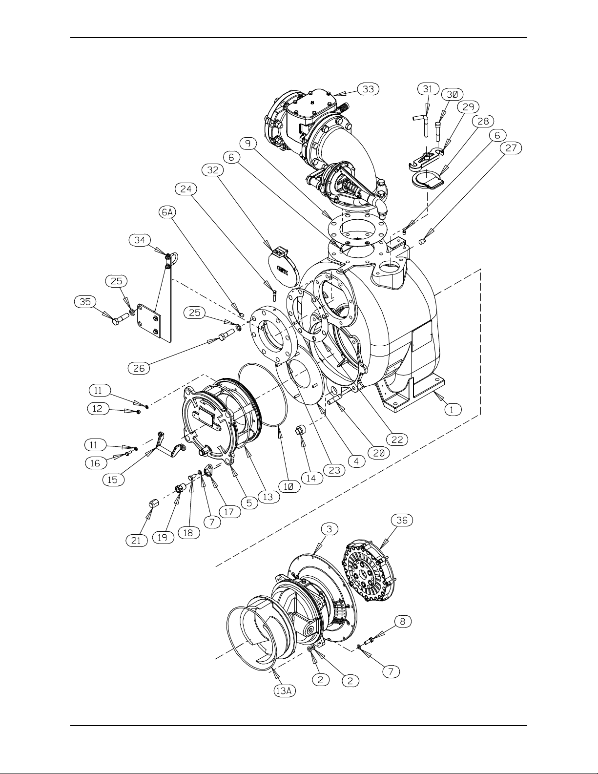
ILLUSTRATION
SUPER T SERIESOM-07174
Figure 3. Pump End Assembly
MAINTENANCE & REPAIRPAGE E - 6
Page 33
SUPER T SERIES OM-07174
PARTS LIST
Pump End Assembly
ITEM
PART NAME PART
NO.
NUMBER
QTY ITEM
NO.
PART NAME PART
NUMBER
QTY
. 1 PUMP CASING SEE NOTE BELOW 1
2 SHIM 13131-3 17040 8
3 REPAIR ROTATING ASSY 44163-547 1
WEAR PLATE 46451-723 24150 1
4
5 BACK CVR PLATE ASSY 42111-803 1
-WARNING PLATE 2613EV 13990 1
-DRIVE SCREW BM#04-03 17000 4
-PRESS RELIEF VALVE 26662-005 1
. 6 PIPE PLUG P04 15079 2
6A PIPE PLUG P04 15079 1
7 LOCK WASHER J08 15991 8
8 HEX HEAD CAP SCREW B0806 15991 4
9 GASKET 25113-036 1
10 O‐RING 25152-453 1
11 LOCK WASHER J06 15991 6
12 HEX NUT D06 15991 4
13 O‐RING S1676 1
13A O‐RING S1676 1
.14 CASING DRAIN PLUG P20 10009 1
15 HANDLE 12354 13010 1
16 HEX HEAD CAP SCREW B0604 15991 2
17 LOCK COLLAR 38115-551 15001 4
18 HEX HEAD CAP SCREW B0804-1/2 15991 4
19 ADJUSTING SCREW 31871-070 1500G 4
.20 STUD C1213 15991 4
21 BACK COVER NUT 31871-073 15000 4
22 SUCT FLANGE GASKET 11402G 19370 1
23 SUCTION FLANGE 11402 10010 1
INDICATES PARTS RECOMMENDED FOR STOCK
24 CHECK VALVE PIN 11645 17010 1
25 LOCK WASHER J12 15991 8
26 HEX HEAD CAP SCREW B1211 15991 6
.27 PIPE PLUG P08 15079 1
28 FILL COVER ASSY 42111-344 1
-DRIVE SCREW BM#04-03 17000 2
-WARNING PLATE 38816-097 13990 1
-COVER GASKET 50G 19210 1
29 CLAMP BAR 38111-004 11010 1
.30 MACHINE BOLT A1014 15991 2
31 CLAMP BAR SCREW 31912-009 15000 1
32 FLAP VALVE ASSY 46411-064 1
33 CHK VLV/AIR REL ASSY 46421-100 1
34 MOUNTING BRKT ASSY 41888-286 1
35 HEX HEAD CAP SCREW B1212 15991 2
36 COUPLING KIT 48112-001 1
NOT SHOWN:
G‐R DECAL GR-06 1
INSTR TAG 38817-085 1
LUBRICATION DECAL 38817-084 1
WARNING DECAL 2613FE 1
SUCTION STICKER 6588AG 1
PRIMING STICKER 6588AH 1
DISCHARGE STICKER 6588BJ 1
SUPER "T" DECAL 38812-089 1
NAME PLATE 38819-002 13000 1
DRIVE SCREW BM#04-03 17000 4
STRAINER ASSY 7823A 24000 1
. INCLUDED WITH REPAIR 46472-722 1
PUMP CASING ASSY
MAINTENANCE & REPAIR PAGE E - 7
Page 34
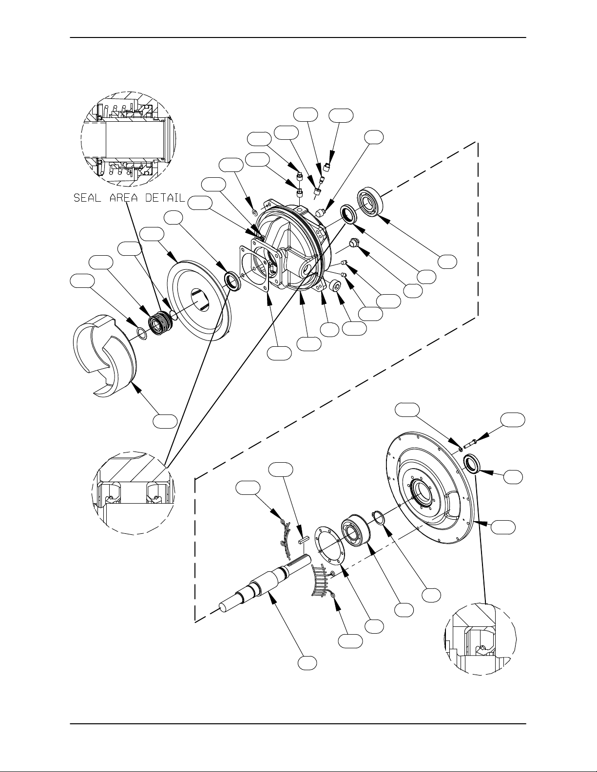
ILLUSTRATION
SUPER T SERIESOM-07174
25
23
19
20
11
12
30
10
28
22
21
4
29
18
30
9
3
4
8
13
13
27
6
24
26
17
15
16
4
14
5
2
7
26
1
Figure 4. Repair Rotating Assembly
MAINTENANCE & REPAIRPAGE E - 8
Page 35
SUPER T SERIES OM-07174
PARTS LIST
Repair Rotating Assembly
ITEM
NO.
1 IMPELLER SHAFT 38514-823 1706H 1
2 BALL BEARING S1030 1
3 BALL BEARING S616 1
4 OIL SEAL S1917 3
5 SNAP RING 24124-425 1
6 BEARING HOUSING 38251-517 10000 1
7 BEARING CAP GASKET 38683-478 18000 1
8 SIGHT GAUGE S1471 2
9 PIPE PLUG P12 15079 1
10 VENTED PIPE PLUG 4823A 15079 1
11 AIR VENT S1530 1
12 REDUCER PIPE BUSHING AP0802 15079 1
13 PIPE PLUG P04 15079 2
14 DRIVE FLANGE 38545-023 10000 1
15 LOCK WASHER J06 15991 8
16 GRADE 8 CAPSCREW 3/8 X 2 21632-938 8
17 SHAFT KEY N0607 15990 1
18 GASKET 10959G 20000 1
19 SHAFT SLEEVE O‐RING 25154-026 REF
20 SEAL PLATE 38272-254 10010 1
21 LOCK WASHER J08 15991 4
22 HEX HEAD CAP SCREW B0805-1/2 15991 4
23 1 7/8 CTG SEAL ASSY 46513-154 1
24 IMPELLER 38615-087 11010 1
25 ADJ SHIM SET 5091 17090 2
26 INTERMEDIATE GUARD 42381-509 24152 2
27 PIPE PLUG PC20 10009 1
28 ROTATING ASSY ADJ SHIM 13131-3 17040 8
29 O‐RING S1676 1
30 SHIPPING PLUG 11495B 15079 2
NOT SHOWN:
PART NAME
ASSEMBLY PLATE 2613GG 13990 1
DRIVE SCREW BM#04-03 17000 2
ROTATION DECAL 2613M 1
INSTRUCTION DECAL 6588U 1
WARNING DECAL 38817-102 1
PART
NUMBER
QTY
INDICATES PARTS RECOMMENDED FOR STOCK
MAINTENANCE & REPAIR PAGE E - 9
Page 36
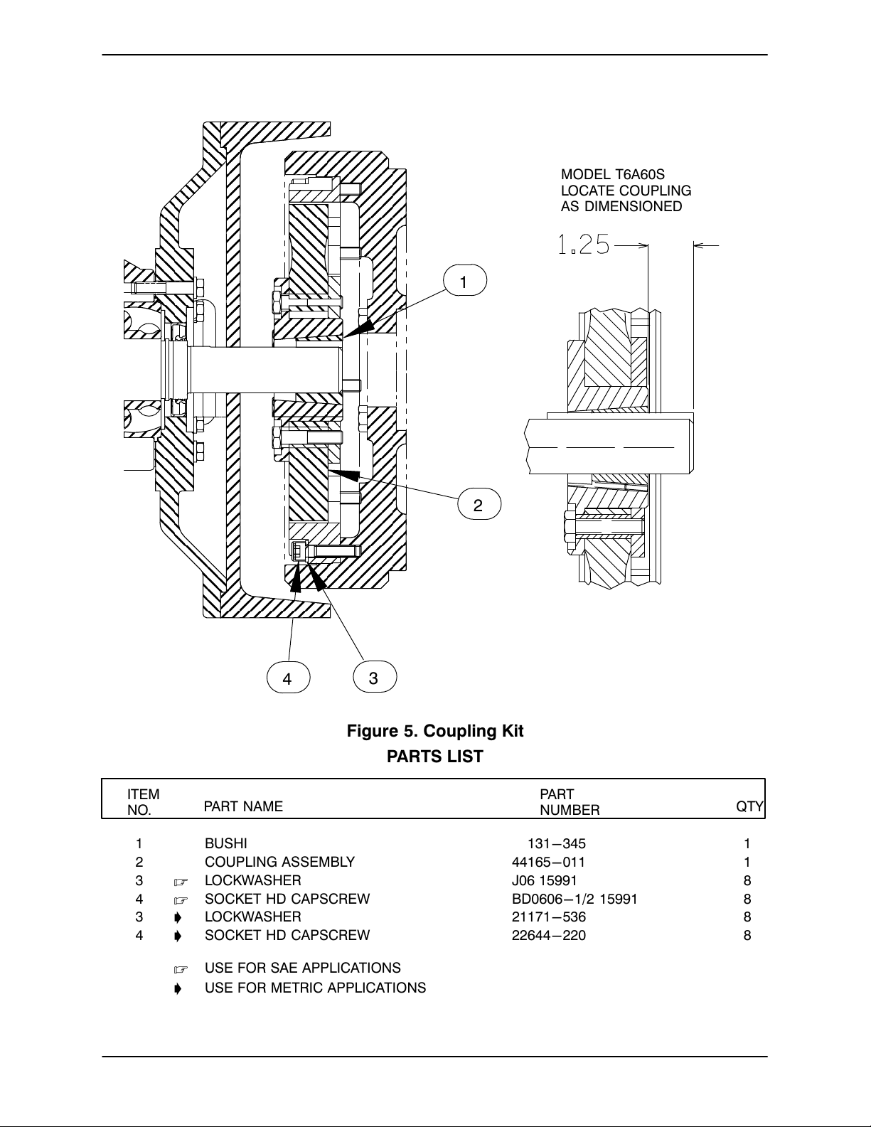
ILLUSTRATION
1
SUPER T SERIESOM-07174
MODEL T6A60S
LOCATE COUPLING
AS DIMENSIONED
2
4
3
Figure 5. Coupling Kit
PARTS LIST
ITEM
NO.
1 BUSHING 24131-345 1
2 COUPLING ASSEMBLY 44165-011 1
3 . LOCKWASHER J06 15991 8
4 . SOCKET HD CAPSCREW BD0606-1/2 15991 8
3 ' LOCKWASHER 21171-536 8
4 ' SOCKET HD CAPSCREW 22644-220 8
PART NAME
PART
NUMBER
QTY
. USE FOR SAE APPLICATIONS
' USE FOR METRIC APPLICATIONS
MAINTENANCE & REPAIRPAGE E - 10
Page 37
SUPER T SERIES
OM-07174
PUMP AND SEAL DISASSEMBLY AND REASSEMBLY
Review all SAFETY information in Section A.
Follow the instructions on all tags, label and de
cals attached to the pump.
This pump requires little service due to its rugged,
minimum‐maintenance design. However, if it be
comes necessary to inspect or replace the wearing
parts, follow these instructions which are keyed to
the illustrations (see Figures 1 through 5) and the
accompanying parts lists.
This manual will alert personnel to
known procedures which require spe
cial attention, to those which could
damage equipment, and to those which
could be dangerous to personnel. How
ever, this manual cannot possibly antici
pate and provide detailed instructions
and precautions for every situation that
might occur during maintenance of the
unit. Therefore, it is the responsibility of
the owner/maintenance personnel to
ensure that only safe, established main
tenance procedures are used, and that
any procedures not addressed in this
manual are performed only after estab
lishing that neither personal safety nor
pump integrity are compromised by
such practices.
Many service functions may be performed by
draining the pump and removing the back cover
assembly. If major repair is required, the piping
and/or engine must be disconnected. The follow
ing instructions assume complete disassembly is
required.
Before attempting to service the pump, disconnect
or lock out the power source and take precautions
to ensure that it will remain inoperative. Close all
valves in the suction and discharge lines.
No instructions for removal and/or disassembly of
the enclosure or its components are provided in
this manual. If removal of the enclosure is required
for pump service, be sure to use safe shop practic
es so as not to endanger personnel, and use cau
tion to prevent damage to the enclosure.
For engine disassembly and repair, consult the lit
erature supplied with the engine, or contact your
local engine representative.
Before attempting to open or service the
pump:
1. Familiarize yourself with this man
ual.
2. Switch off the engine ignition and
disconnect the positive battery
cable to ensure that the pump will
remain inoperative.
3. Allow the pump to completely cool
if overheated.
4. Check the temperature before
opening any covers, plates, or
plugs.
5. Close the suction and discharge
valves.
6. Vent the pump slowly and cau
tiously.
7. Drain the pump.
Death or serious personal injury and
damage to the pump or components
can occur if proper lifting procedures
are not observed. Make certain that
hoists, chains, slings or cables are in
good working condition and of suffi
cient capacity and that they are posi
tioned so that loads will be balanced
and the pump or components will not be
damaged when lifting. Suction and dis
charge hoses and piping must be re
moved from the pump before lifting. Lift
the pump or component only as high as
necessary and keep personnel away
from suspended objects.
MAINTENANCE & REPAIR PAGE E - 11
Page 38
OM-07174 SUPER T SERIES
Suction Check Valve Removal
(Figure 3)
If the check valve assembly (32) is to be serviced,
Use Only Genuine Gorman-Rupp re
placement parts. Failure to do so may cre
ate a hazard and damage the pump or di
remove the check valve pin (24), reach through the
back cover opening and pull the complete assem
bly from the suction flange (23).
minish optimal pump performance. Any
such hazard, damage or diminished per
formance is not covered by the warranty.
NOTE
When appropriate recycling facilities are available,
the user should recycle components and fluids
when doing any routine maintenance / repairs and
also at the end of the pump’s useful life. All other
components and fluids shall be disposed of ac
cording to all applicable codes and regulations.
Back Cover and Wear Plate Removal
(Figure 3)
Further disassembly of the check valve is not re
quired since it must be replaced as a complete unit.
Individual parts are not sold separately.
Separating Intermediate and Coupling
Assembly From Engine
(Figure 5)
Further disassembly requires separating the pump
end and drive assembly from the engine. Remove
the hardware securing the check valve/air release
valve assembly (33, Figure 3) to the pump casing.
Disengage and remove any additional compo
nents necessary for the removal of the pump end.
NOTE
The wear plate (4) is easily accessible and may be
serviced by removing the back cover assembly (5).
Before attempting to service the pump, open the
ball valve (87, Figure 2) and drain the pump. Close
the valve after draining is complete.
Remove the back cover nuts (21) and pry the back
cover and assembled wear plate from the pump
casing (1).
NOTE
An alternate method of removing the back cover
from the pump casing is to remove the back cover
nuts (21) and two diagonally opposing locking col
lars (17). Install two 1/2-16 UNC x 2 inch long
screws in the tapped holes in the back cover and
use them to press the back cover out of the pump
casing.
Inspect the wear plate and replace it if badly scored
or worn. To remove the wear plate, disengage the
hardware (11 and 12).
Install a standard 5/8‐11 UNC lifting eye in the
tapped hole in the top of the pump casing. Be sure
to screw the eye into the casing until fully engaged.
Support the pump using a suitable hoist and the
lifting eye.
Do not attempt to lift the complete pump
unit using the lifting eye. It is designed
to facilitate removal or installation of in
dividual components only. Additional
weight may result in damage to the
pump or failure of the eye bolt.
Remove the hardware securing the pump casing
to the base.
Disengage the hardware (7 and 8, Figure 3) secur
ing the drive flange to the engine bellhousing, and
remove the guards (26, Figure 4). Separate the
pump end and drive assembly from the engine by
pulling the pump end straight away from the en
gine.
Inspect the back cover and wear plate O‐rings (10
and 13) and replace them if damaged or worn.
As the assemblies separate, the flexible portion of
the coupling assembly (2) will remain on the shaft.
MAINTENANCE & REPAIRPAGE E - 12
Page 39
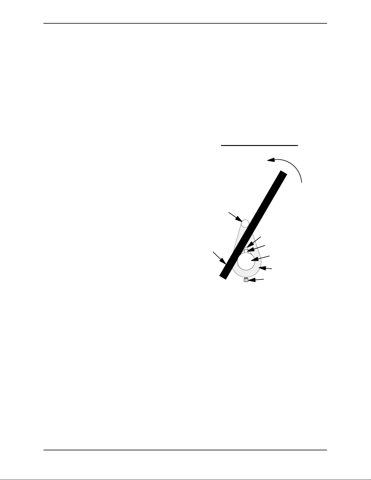
SUPER T SERIES
OM-07174
To remove the coupling from the shaft, unscrew the
two allen head setscrews from the bushing (1).
Screw one of the setscrews into the puller hole on
the circumference of the bushing. As the coupling
and bushing separate, remove the bushing, and
slide the coupling off the shaft. Remove the shaft
key (17, Figure 4).
It is not necessary to remove the outer ring of the
coupling from the engine flywheel unless the cou
pling must be replaced. To remove the ring, disen
gage the hardware (3 and 4) securing it to the fly
wheel.
Remove any leveling shims used under the casing
mounting feet. Tie and tag the shims for ease of
reassembly.
Move the pump end to a clean, well equipped shop
area for further disassembly.
shaft (1) with the “V” notch positioned over the
shaft key.
With the impeller rotation still blocked, see Figure 6
and use a long piece of heavy bar stock to pry
against the arm of the lathe dog in a counterclock
wise direction (when facing the drive end of the
shaft). Use caution not to damage the shaft or key
way. When the impeller breaks loose, remove the
lathe dog, key and wood block.
NOTE
Do not remove the impeller until the rotating assem
bly has been removed from the pump casing.
Turn
Counterclockwise
Lathe Dog Arm
Loosening Impeller
(Figure 4)
Before attempting to loosen the impeller, remove
the seal cavity drain plug (13) and drain the lubri
cant. This will prevent the oil from escaping as the
impeller is removed. Clean and reinstall the drain
plug.
With the pump end separated from the engine and
the back cover (5, Figure 3) removed, wedge a
block of wood between the vanes of the impeller
and the pump casing to prevent rotation.
If removed, install the shaft key (17) in the shaft
keyway. Install a lathe dog on the drive end of the
“V” Notch
Heavy
Bar Stock
Figure 6. Loosening Impeller
Rotating Assembly Removal
(Figure 3)
Remove the hardware (7 and 8) securing the rotat
ing assembly to the pump casing. Separate the ro
tating assembly by pulling straight away from the
pump casing. Tie and tag the rotating assembly
shims (2) for ease of reassembly.
Shaft Key
Impeller
Shaft
Lathe Dog
Setscrew
MAINTENANCE & REPAIR PAGE E - 13
Page 40
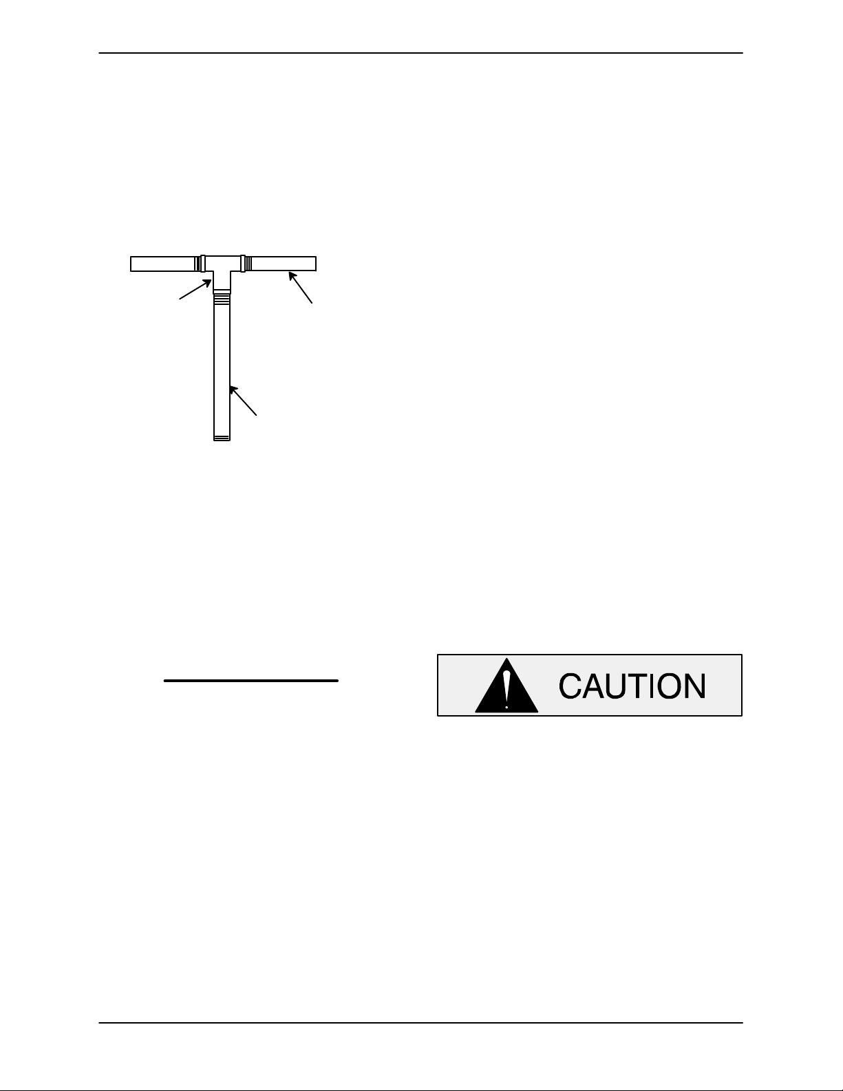
OM-07174 SUPER T SERIES
NOTE
An optional disassembly tool is available from the
factory. If the tool is used, follow the instructions
packed with it. A similar tool may be assembled us
ing 1/2‐inch pipe (schedule 80 steel or malleable
iron) and a standard tee (see Figure 7). All threads
are 1/2‐inch NPT. Do not pre‐assemble the tool.
TEE
APPROX. 6 IN.
(152 MM) LONG
APPROX. 14 IN.
(356 MM) LONG
Seal Removal
(Figure 4)
Slide the integral shaft sleeve and rotating portion
of the seal off the shaft as a unit.
Use a pair of stiff wires with hooked ends to remove
the stationary element and seat.
An alternate method of removing the stationary
seal components is to remove the hardware (21
and 22) and separate the seal plate (20) and gas
ket (18) from the bearing housing (6). Position the
seal plate on a flat surface with the impeller side
down. Use a wooden dowel or other suitable tool to
press on the back side of the stationary seat until
the seat, O‐rings, and stationary element can be
removed.
Remove the shaft sleeve O‐ring (19).
If no further disassembly is required, refer to Seal
Installation.
Figure 7. Rotating Assembly Tool
To install the tool, remove the vented plug (10, Fig
ure 4) from the bearing housing, and screw the
longest length of pipe into the vent hole until fully
engaged. Install the tee, and screw the handles into
the tee. Use caution when lifting the rotating assem
bly to avoid injury to personnel or damage to the as
sem
bly.
Remove the bearing housing O‐ring (13A).
Impeller Removal
(Figure 4)
With the rotating assembly removed from the
pump casing, unscrew the impeller from the shaft.
Use caution when unscrewing the impeller; ten
sion on the shaft seal spring will be released as the
impeller is removed. Inspect the impeller and re
place if cracked or badly worn.
Shaft and Bearing Removal and Disassembly
(Figure 4)
When the pump is properly operated and main
tained, the bearing housing should not require dis
assembly. Disassemble the shaft and bearings
only when there is evidence of wear or damage.
Shaft and bearing disassembly in the field
is not recommended. These operations
should be performed only in a properly‐
equipped shop by qualified personnel.
Remove the bearing housing drain plug (13) and
drain the lubricant. Clean and reinstall the drain
plug.
Disengage the hardware (15 and 16) and slide the
drive flange (14) and oil seal (4) off the shaft. Re
move the flange gasket (7) and press the oil seal
from the drive flange.
Remove the impeller adjusting shims (25); tie and
tag the shims, or measure and record their thick
ness for ease of reassembly.
Place a block of wood against the impeller end of
the shaft and tap the shaft and assembled bear
ings (2 and 3) from the bearing housing.
MAINTENANCE & REPAIRPAGE E - 14
Page 41
SUPER T SERIES
OM-07174
Pry or press the oil seals (4 ) from the bearing hous
ing.
After removing the shaft and bearings, clean and
inspect the bearings in place as follows.
To prevent damage during removal from
the shaft, it is recommended that bearings
be cleaned and inspected in place. It is
strongly recommended that the bearings
be replaced any time the shaft and bear
ings are removed.
Clean the bearing housing, shaft and all compo
nent parts (except the bearings) with a soft cloth
soaked in cleaning solvent. Inspect the parts for
wear or damage and replace as necessary.
Most cleaning solvents are toxic and
flammable. Use them only in a well ven
tilated area free from excessive heat,
sparks, and flame. Read and follow all
precautions printed on solvent contain
ers.
Clean the bearings thoroughly in fresh cleaning
solvent. Dry the bearings with filtered compressed
air and coat with light oil.
housing. Replace the bearings, shaft, or bearing
housing if the proper bearing fit is not achieved.
If bearing replacement is required, remove the out
board bearing snap ring (5) and use a bearing pull
er to remove the bearings from the shaft.
Shaft and Bearing Reassembly and Installation
(Figure 4)
Clean the bearing housing, shaft and all compo
nent parts (except the bearings) with a soft cloth
soaked in cleaning solvent. Inspect the parts for
wear or damage as necessary.
Most cleaning solvents are toxic and
flammable. Use them only in a well ven
tilated area free from excessive heat,
sparks, and flame. Read and follow all
precautions printed on solvent contain
ers.
Inspect the shaft for distortion, nicks or scratches,
or for thread damage on the impeller end. Dress
small nicks and burrs with a fine file or emery cloth.
Replace the shaft if defective.
Position the inboard oil seal (4) in the bearing hous
ing bore with the lip positioned as shown in Figure
5. Press the oil seal into the housing until the face is
just flush with the machined surface on the inside
of the housing.
Bearings must be kept free of all dirt and
foreign material. Failure to do so will great
ly shorten bearing life. Do not spin dry
bearings. This may scratch the balls or
races and cause premature bearing fail
ure.
Rotate the bearings by hand to check for rough
ness or binding and inspect the bearing balls. If ro
tation is rough or the bearing balls are discolored,
replace the bearings.
The bearing tolerances provide a tight press fit
onto the shaft and a snug slip fit into the bearing
MAINTENANCE & REPAIR PAGE E - 15
To prevent damage during removal from
the shaft, it is recommended that bearings
be cleaned and inspected in place. It is
strongly recommended that the bearings
be replaced any time the shaft and bear
ings are removed.
NOTE
Position the inboard bearing (3) on the shaft with
the shielded side toward the impeller end of the
shaft. Position the outboard bearing (2) on the shaft
with the integral retaining ring on the bearing O.D.
toward the drive end of the shaft.
Page 42
OM-07174 SUPER T SERIES
The bearings may be heated to ease installation.
An induction heater, hot oil bath, electric oven, or
hot plate may be used to heat the bearings. Bear
ings should never be heated with a direct flame or
directly on a hot plate.
NOTE
If a hot oil bath is used to heat the bearings, both the
oil and the container must be absolutely clean. If
the oil has been previously used, it must be thor
oughly filtered.
Heat the bearings to a uniform temperature no
higher than 250_F (120_C) and slide the bearings
onto the shaft, one at a time, until they are fully
seated. This should be done quickly, in one con
tinuous motion, to prevent the bearings from cool
ing and sticking on the shaft.
After the bearings have been installed and allowed
to cool, check to ensure that they have not moved
away from the shaft shoulders in shrinking. If
movement has occurred, use a suitably sized
sleeve and a press to reposition the bearings
against the shaft shoulders.
With the lip seal sleeve in place, lubricate the lip
seal area of the shaft, and slide the shaft and as
sembled bearings into the bearing housing until
the retaining ring on the outboard bearing seats
against the bearing housing. Remove the lip seal
sleeve.
When installing the shaft and bearings into
the bearing bore, push against the outer
race. Never hit the balls or ball cage.
Position the outboard oil seal (4) on the lubricated
shaft with the lip positioned as shown in Figure 4.
Press the oil seal into the bearing housing until the
face of the seal is just flush with the machined sur
face on the bearing housing.
Press the oil seal (4) into the drive flange (14) with
the lip positioned as shown in Figure 4. Replace
the flange gasket (7) and secure the flange to the
bearing housing with the hardware (15 and 16). Be
careful not to damage the oil seal lip on the shaft
keyway.
If heating the bearings is not practical, use a suit
ably sized sleeve, and an arbor (or hydraulic) press
to install the bearings on the shaft.
When installing the bearings onto the
shaft, never press or hit against the outer
race, balls, or ball cage. Press only on the
inner race.
Secure the outboard bearing on the shaft with the
bearing snap ring (5).
It is recommended that a sleeve be positioned
against the inboard oil seal (4) to prevent the lip of
the oil seal from rolling as the shaft and bearings
are installed in the bearing housing. The O.D. of the
sleeve should be just smaller than the bearing
housing bore, while the I.D. of the sleeve should be
just larger than the O.D. of the lip seal area of the
shaft.
Lubricate the bearing housing as indicated in LU
BRICATION.
Seal Installation
(Figures 4, 8, 9 and 10)
Most cleaning solvents are toxic and
flammable. Use them only in a well ven
tilated area free from excessive heat,
sparks, and flame. Read and follow all
precautions printed on solvent contain
ers.
Clean the seal cavity and shaft with a cloth soaked
in fresh cleaning solvent. Inspect the stationary
seat bore in the seal plate for dirt, nicks and burrs,
and remove any that exist. The stationary seat bore
must be completely clean before installing the
seal.
MAINTENANCE & REPAIRPAGE E - 16
Page 43
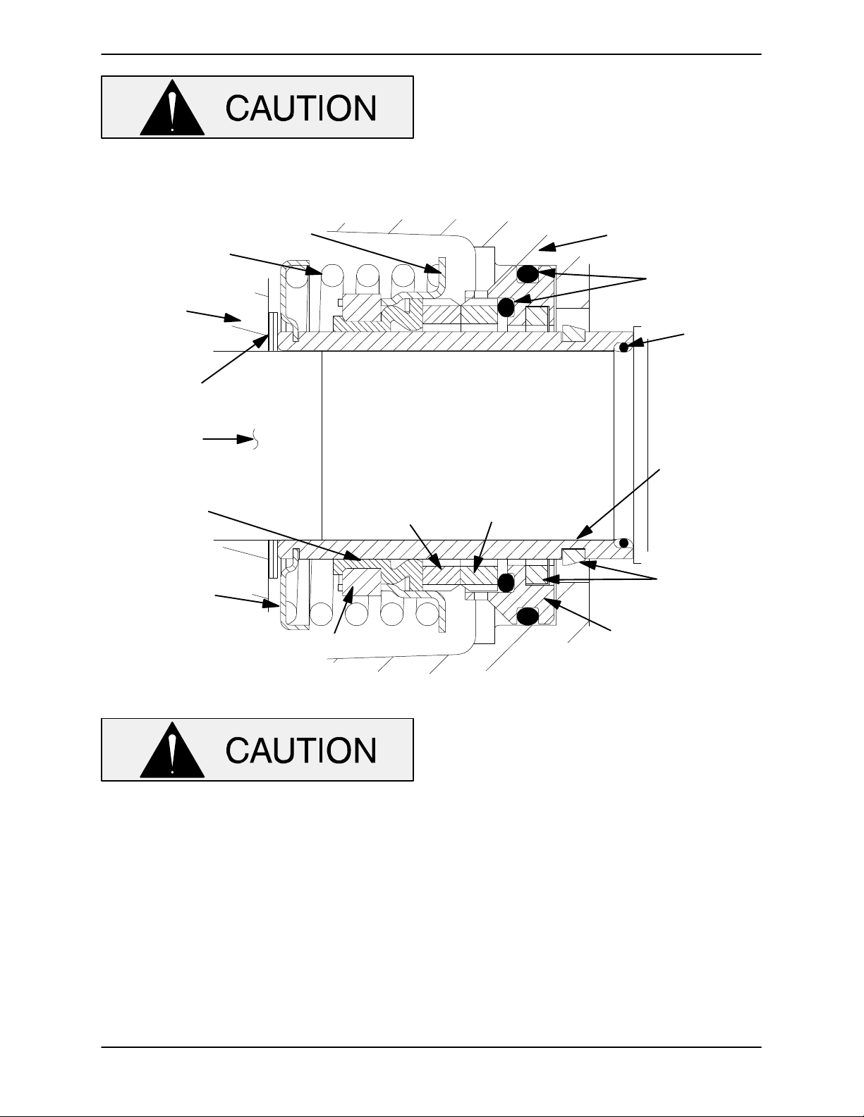
SUPER T SERIES
A new seal assembly should be installed
any time the old seal is removed from the
pump. Wear patterns on the finished faces
OM-07174
cannot be realigned during reassembly.
Reusing an old seal could result in prema
ture failure.
To ease installation of the seal, lubricate the shaft
sleeve O‐ring (19) and the external stationary seat
O‐ring with a very small amount of light lubricating
oil. See Figure 8 for seal part identification.
SPRING
IMPELLER
IMPELLER
SHIMS
IMPELLER
SHAFT
BELLOWS
SPRING
CENTERING
WASHER
RETAINER
DRIVE BAND
ROTATING
ELEMENT
STATIONARY
ELEMENT
SEAL PLATE
O‐RINGS
SLEEVE
O‐RING
INTEGRAL
SHAFT
SLEEVE
SHEAR
RING
(SHEARED)
STATIONARY
SEAT
Figure 8. Cartridge Seal Assembly
tape covering the threads. Check to ensure that
the shaft threads are free of any tape residue and
clean as required before proceeding with seal
installation.
This seal is not designed for operation at
temperatures above 160_F (71_C). Do not
use at higher operating temperatures.
If the seal plate (20) was removed, install the seal
plate gasket (18), position the seal plate over the
shaft and secure it to the bearing housing with the
hardware (21 and 22). Install the bearing housing
O‐ring (29) and lubricate it with light grease.
To prevent damaging the shaft sleeve O‐ring (19)
on the shaft threads, cover the threads with electri
cal or duct tape. Slide the O‐ring over the shaft until
it seats against the shaft shoulder. Remove the
MAINTENANCE & REPAIR PAGE E - 17
When installing a new cartridge seal assembly,
remove the seal from the container lubricate the ex
ternal stationary seat O‐ring with light oil. Slide the
seal assembly onto the shaft until the external sta
tionary seat O‐ring engages the bore in the seal
plate.
Clean and inspect the impeller as described in Im
peller Installation and Adjustment. Install the full
set of impeller shims (25) provided with the seal,
and screw the impeller onto the shaft until it is
seated against the seal (see Figure 9).
Page 44
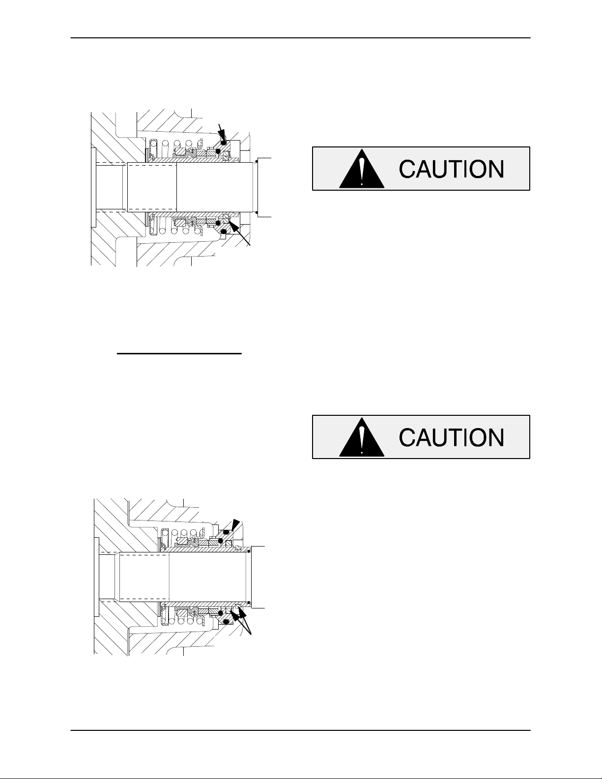
OM-07174 SUPER T SERIES
Continue to screw the impeller onto the shaft. This
will press the stationary seat into the seal plate
bore.
O‐RING ENGAGED
WITH SEAL PLATE
BORE
SHEAR RING
(UNSHEARED)
Figure 9. Seal Partially Installed
NOTE
A firm resistance will be felt as the impeller presses
the stationary seat into the seal plate bore.
As the stationary seat becomes fully seated, the
seal spring compresses, and the shaft sleeve will
break the nylon shear ring. This allows the sleeve
to slide down the shaft until seated against the
shaft shoulder. Continue to screw the impeller onto
the shaft until the impeller, shims, and sleeve are
fully seated against the shaft shoulder (see Figure
10).
STATIONARY SEAT
FULLY SEATED IN
SEAL PLATE BORE
proper clearance as described in Impeller Instal
lation and Adjustment.
If necessary to reuse an old seal in an emer
gency, carefully separate the rotating and station
ary seal faces from the bellows retainer and sta
tionary seat.
A new seal assembly should be installed
any time the old seal is removed from the
pump. Wear patterns on the finished faces
cannot be realigned during reassembly.
Reusing an old seal could result in prema
ture failure.
Handle the seal parts with extreme care to prevent
damage. Be careful not to contaminate precision
finished faces; even fingerprints on the faces can
shorten seal life. If necessary, clean the faces with a
non‐oil based solvent and a clean, lint‐free tissue.
Wipe lightly in a concentric pattern to avoid
scratching the faces.
Carefully wash all metallic parts in fresh cleaning
solvent and allow to dry thoroughly.
Do not attempt to separate the rotating
portion of the seal from the shaft sleeve
when reusing an old seal. The rubber bel
lows will adhere to the sleeve during use,
and attempting to separate them could
damage the bellows.
SHEAR RING
(SHEARED)
Figure 10. Seal Fully Installed
Measure the impeller‐to‐seal plate clearance, and
remove impeller adjusting shims to obtain the
Inspect the seal components for wear, scoring,
grooves, and other damage that might cause leak
age. Inspect the integral shaft sleeve for nicks or
cuts on either end. If any components are worn, or
the sleeve is damaged, replace the complete seal;
never mix old and new seal parts.
Install the stationary seal element in the stationary
seat. Press this stationary subassembly into the
seal plate bore until it seats squarely against the
bore shoulder. A push tube made from a piece of
plastic pipe would aid this installation. The I.D. of
the pipe should be slightly larger than the O.D. of
the shaft sleeve.
MAINTENANCE & REPAIRPAGE E - 18
Page 45
SUPER T SERIES
OM-07174
Slide the rotating portion of the seal (consisting of
the integral shaft sleeve, spring centering washer,
spring, bellows and retainer, and rotating element)
onto the shaft until the seal faces contact.
Proceed with Impeller Installation and Adjust
ment.
Impeller Installation and Adjustment
(Figure 4)
Inspect the impeller, and replace it if cracked or
badly worn. Inspect the impeller and shaft threads
for dirt or damage, and clean or dress the threads
as required.
The shaft and impeller threads must be
completely clean before reinstalling the im
peller. Even the slightest amount of dirt on
the threads can cause the impeller to seize
to the shaft, making future removal difficult
or impossible without damage to the im
peller or shaft.
Install the same thickness of impeller adjusting
shims (25) as previously removed. Apply `Never‐
Seez' or equivalent to the shaft threads and screw
the impeller onto the shaft until tight. Be sure the
seal spring seats squarely on the back side of the
impeller.
Rotating Assembly Installation
(Figure 3)
NOTE
If the pump has been completely disassembled, it
is recommended that the suction check valve and
back cover assembly be reinstalled at this point.
The back cover assembly must be in place to adjust
the impeller face clearance.
NOTE
There is a 1‐1/2 inch diameter socket head pipe
plug located in the side of the bearing housing. This
hole is required for manufacturing purposes only;
therefore the pipe plug should never require remov
al.
Install the bearing housing O‐ring (13A) and lubri
cate it with light grease. Ease the rotating assem
bly into the pump casing using the installation tool.
Be careful not to damage the O‐ring.
Install the rotating assembly adjusting shims (2)
using the same thickness as previously removed.
Secure the rotating assembly to the pump casing
with the hardware (7 and 8).
To set the impeller and wear plate clearance refer
to the Back Cover Installation And Adjustment.
Suction Check Valve Installation
(Figure 3)
NOTE
At the slightest sign of binding, immediately back
the impeller off, and check the threads for dirt. Do
not try to force the impeller onto the shaft.
A clearance of .025 to .040 inch (0,64 to 1,02 mm)
between the impeller and the seal plate is recom
mended for maximum pump efficiency. Measure
this clearance, and add or remove impeller adjust
ing shims as required.
NOTE
If the rotating assembly has been installed in the
pump casing, this clearance may be measured by
reaching through the priming port with a feeler
gauge.
MAINTENANCE & REPAIR PAGE E - 19
Inspect the check valve assembly (32) and replace
it if badly worn.
NOTE
The check valve assembly must be replaced as a
complete unit. Individual parts are not sold sepa
rately.
Reach through the back cover opening with the
check valve and position the check valve adaptor
in the mounting slot in the suction flange (23). Align
the adaptor with the flange hole and secure the as
sembly with the check valve pin (24).
NOTE
If the suction or discharge flanges were removed,
replace the respective gaskets, apply `Permatex
Page 46
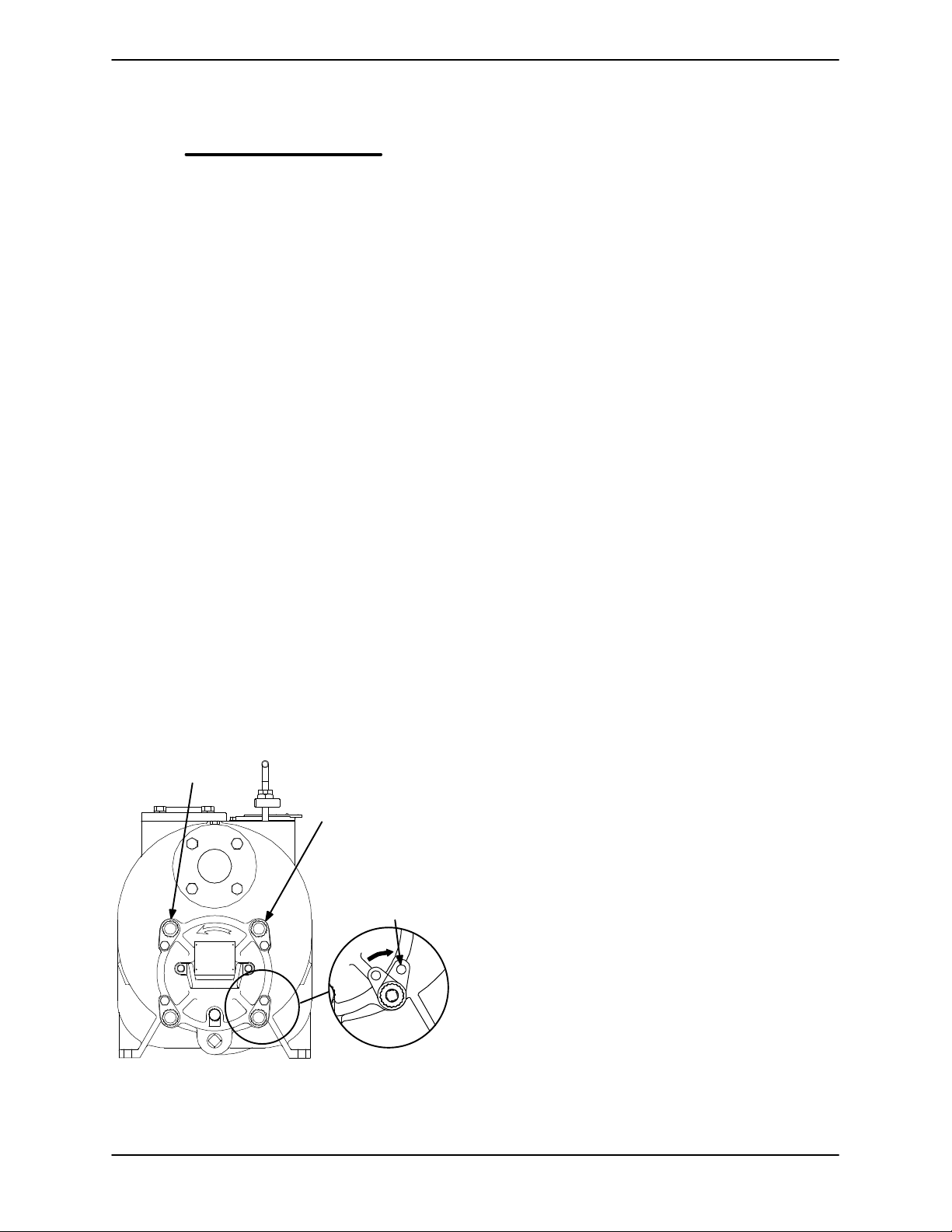
OM-07174 SUPER T SERIES
Aviation No. 3 Form‐A‐Gasket' or equivalent com
pound to the mating surfaces, and secure them to
the pump casing with the attaching hardware.
Back Cover Installation and Adjustment
(Figures 3 and 11)
If the wear plate (4) was removed for replacement,
carefully center it on the back cover and secure it
with the hardware (11 and 12). The wear plate
must be concentric to prevent binding when the
back cover is installed.
The clearance between the impeller and wear plate
is adjusted using four adjusting screws (19) and
locking collars (17). There are 18 detents on the
I.D. of each locking collar. Indexing the collars one
detent on the adjusting screws represents approxi
mately .005 inch (0,13 mm) of wear plate clear
ance. The recommended clearance between the
wear plate and the impeller is .010 to .020 inch
(0,25 to 0,50 mm).
Replace the back cover and wear plate O‐rings (10
and 13) and lubricate them with a generous
amount of No. 2 grease. Clean any scale or debris
from the contacting surfaces in the pump casing
that might interfere or prevent a good seal with the
back cover.
USE TWO REMAINING
ADJUSTING SCREWS AND
LOCKING COLLARS TO
SET FACE CLEARANCE
USE TWO
OPPOSING
BACK COVER NUTS
TO PRESS
BACK COVER
INTO PUMP
CASING
INDEX COLLARS 3
DETENTS COUNTER‐
CLOCKWISE, THEN
TURN CLOCKWISE
UNTIL SCREW
HOLES ALIGN
just flush with the machined surface on the back
side of the cover plate.
Align the back cover plate over the studs (20) and
slide it into the pump casing. Use two back cover
nuts (21) on diagonally opposing studs to press
the back cover into the pump casing until the wear
plate just touches the impeller when the shaft is
turned by hand. Tighten the back cover nuts
evenly to avoid binding.
With the wear plate just touching the impeller, turn
the two free adjusting screws until they engage the
pump casing. Position the locking collars over the
adjusting screws so the holes in the collars for the
locking screws align approximately with the holes
in the cover plate.
Loosen the back cover nuts used to press the back
cover into the pump casing one full turn.
Pull the collars off the adjusting screws, index them
three detents counterclockwise, and reinstall the
collars on the adjusting screws. Use the collars to
turn the adjusting screws clockwise until the holes
in the locking collars realign with the tapped screw
holes in the back cover plate. Secure the locking
collars to the back cover plate with the hardware (7
and 18). Install the two remaining back cover nuts
snugly against the adjusting screws.
Remove the first two back cover nuts from their
studs. Turn the adjusting screws clockwise until
they engage the pump casing. Install the locking
collars and hardware (7 and 18). Reinstall the back
cover nuts.
Be sure the wear plate does not scrape against the
impeller.
Over time it may be necessary to repeat the adjust
ment process to compensate for normal wear be
tween the impeller and wear plate. When all of the
adjustment has been used on the back cover side
of the pump, an additional 0.125 inch (3,2 mm) of
adjustment may be obtained by removing the ro
tating assembly adjusting shims (2).
Figure 11. Installing and Adjusting Back Cover
Screw the four adjusting screws (19) into the
tapped holes in the back cover plate until they are
Allow an installed pump to completely cool before
draining liquid from the pump casing. Remove the
back cover. Remove the rotating assembly adjust
ing shims, then reinstall the hardware securing the
rotating assembly to the pump casing. Perform the
back cover adjustment procedure described
above to obtain the proper face clearance.
MAINTENANCE & REPAIRPAGE E - 20
Page 47
SUPER T SERIES
OM-07174
Securing Pump and Coupling Assembly to
Engine
(Figure 5)
Install the shaft key (17, Figure 4) in the shaft key
way. Position the flexible portion of the coupling as
sembly (2) on the shaft as shown in Figure 5.
Align the keyway in the bushing (1) with the shaft
key, and slide it onto the shaft to the dimension
shown in Figure 8. Rotate the flexible portion of the
coupling until the tapped holes for the two set
screws align with those in the bushing, and install
the setscrews.
Make certain that the flexible portion of the
coupling is mounted as shown in Figure 5.
This is critical. If the coupling is not prop
erly positioned on the shaft, the coupling
parts may not fully engage, or a pre‐load
condition can cause premature bearing
failure.
NOTE
To ease installation, lightly lubricate the rubber por
tion of the coupling with a non‐petroleum based
lubricant such as vegetable oil or glycerin, or a sili
con‐based lubricant such as “WD40” or equivalent.
Do not use petroleum‐based lubricants, or any oth
er substance which may soften or otherwise dam
age the rubber.
Install the intermediate guards (26, Figure 4), and
secure the drive flange to the engine bellhousing
with the hardware (7 and 8, Figure 3).
Secure the check valve/air release valve assembly
(33, Figure 3) to the pump casing using the pre
viously removed hardware. Reinstall any additional
components removed at disassembly.
Install any leveling shims used under the casing
mounting feet, and secure the casing to the base
with the previously removed hardware.
If a lifting eye was used to move the pump casing,
be sure to remove the lifting eye from the pump
casing.
The end of the shaft must protrude 1.25
inch (32 mm) from the face of the bush
ing. This will allow the two portions of the
coupling to fully engage when the drive
flange is secured to the engine bellhous
ing, without pre‐loading the bearings.
With the flexible portion of the coupling and the
bushing properly positioned on the shaft, tighten
the two setscrews in an alternating sequence until
the bushing and coupling are fully secured. Torque
the setscrews to 14.6 ft. lbs. (175 in. lbs. or 2 m.
kg.).
If the complete coupling assembly is being re
placed, apply `Loctite Retaining Compound No.
242' or equivalent to the threads of the hardware (3
and 4) and secure the outer ring of the coupling to
the engine flywheel by torquing the hardware to 45
ft. lbs. (540 in. lbs. or 6,2 m. kg.).
Using a suitable lifting device, position the pump
end so the flexible portion of the coupling seats in
side the outer ring attached to the engine flywheel.
Do not attempt to lift the complete pump
unit using the lifting eye. It is designed
to facilitate removal or installation of in
dividual components only. Additional
weight may result in damage to the
pump or failure of the eye bolt.
PRESSURE RELIEF VALVE
MAINTENANCE
(Figure 3)
The back cover is equipped with a pressure relief
valve (not shown) to provide additional safety for
the pump and operator (refer to Liquid Tempera
ture And Overheating in OPERATION).
It is recommended that the pressure relief valve as
sembly be replaced at each overhaul, or any time
the pump overheats and activates the valve. Never
replace this valve with a substitute which has not
MAINTENANCE & REPAIR PAGE E - 21
Page 48
OM-07174 SUPER T SERIES
been specified or provided by the Gorman‐Rupp
Company.
Periodically, the valve should be removed for in
spection and cleaning. When reinstalling the relief
valve, apply `Loctite Pipe Sealant With Teflon No.
592', or equivalent compound, on the relief valve
threads. Position the valve as shown in Figure 3
with the discharge port pointing down.
Final Pump Assembly
Be sure the pump is secured to the base and en
gine. Be sure to install any guards used over the ro
tating members.
Do not operate the pump without the
guards in place over the rotating parts.
Exposed rotating parts can catch cloth
ing, fingers, or tools, causing severe in
jury to personnel.
Install the suction and discharge lines and open all
valves. Make certain that all piping connections are
tight, properly supported and secure.
ounces (1,9 liter) of SAE No. 30 non‐detergent oil to
the middle of the sight gauge (8) and maintain it at
the middle of the gauge. Clean and reinstall the
vented plug. Maintain the oil at this level.
Bearings
(Figure 4)
The bearing housing was fully lubricated when
shipped from the factory. Check the oil level regu
larly through the sight gauge (8) and maintain it at
the middle of the gauge. When lubrication is re
quired, add SAE No. 30 non‐detergent oil through
the hole for the air vent (11). Do not over‐lubricate.
Over‐lubrication can cause the bearings to over‐
heat, resulting in premature bearing failure.
Under normal conditions, drain the bearing hous
ing once each year and refill with approximately 21
ounces (0,6 liter) clean oil. Change the oil more fre
quently if the pump is operated continuously or in
stalled in an environment with rapid temperature
change.
Be sure the pump and engine have been properly
lubricated, see LUBRICATION.
Remove the fill cover assembly (28, Figure 3) and
fill the pump casing with clean liquid. Reinstall the
fill cover and tighten it. Refer to OPERATION, Sec
tion C, before putting the pump back into service.
LUBRICATION
Seal Assembly
(Figure 4)
Before starting the pump, remove the vented plug
(10) and fill the seal cavity with approximately 64
Monitor the condition of the bearing lubri
cant regularly for evidence of rust or mois
ture condensation. This is especially im
portant in areas where variable hot and
cold temperatures are common.
For cold weather operation, consult the factory or a
lubricant supplier for the recommended grade of
oil.
Engine
Consult the literature supplied with the engine, or
contact your local engine representative.
MAINTENANCE & REPAIRPAGE E - 22
Page 49

For Warranty Information, Please Visit
www.grpumps.com/warranty
or call:
U.S.: 419-755-1280
Canada: 519-631-2870
International: +1-419-755-1352
GORMAN‐RUPP PUMPS
 Loading...