

Page 1
ACDE
OM-06460-01
March 22, 2012
Rev. C 01‐09‐14
INSTALLATION, OPERATION,
AND MAINTENANCE MANUAL
WITH PARTS LIST
SUBMERSIBLE PUMP
MODEL
SF4B
THE GORMAN‐RUPP COMPANY D MANSFIELD, OHIO
www.grpumps.com
GORMAN‐RUPP OF CANADA LIMITED D ST. THOMAS, ONTARIO, CANADA Printed in U.S.A.
e2012 The Gorman‐Rupp Company
Page 2

Register your new
Gorman‐Rupp pump online at
www.grpumps.com
Valid serial number and e‐mail address required.
RECORD YOUR PUMP MODEL AND SERIAL NUMBER
Please record your pump model and serial number in the
spaces provided below. Your Gorman‐Rupp distributor
needs this information when you require parts or service.
Pump Model:
Serial Number:
Page 3

TABLE OF CONTENTS
INTRODUCTION PAGE I - 1.................................................
SAFETY ‐ SECTION A PAGE A - 1............................................
INSTALLATION - SECTION B PAGE B - 1....................................
PREINSTALLATION INSPECTION PAGE B - 1............................................
PUMP SEALS PAGE B - 1.............................................................
LUBRICATION PAGE B - 1.............................................................
PUMP INSTALLATION PAGE B - 1......................................................
Pump Dimensions PAGE B - 1.....................................................
Pump Motor Specifications PAGE B - 1..............................................
Lifting PAGE B - 2.................................................................
Positioning the Pump PAGE B - 2...................................................
Piping PAGE B - 2................................................................
ELECTRICAL CONNECTIONS PAGE B - 3...............................................
Field Wiring Connections (Incoming Power) PAGE B - 3...............................
Dual Vlotage PAGE B - 3..........................................................
Motor Cable Grounding Test PAGE B - 3.............................................
Control Box Connections PAGE B - 4...............................................
Liquid Level Devices PAGE B - 5....................................................
OPERATION - SECTION C PAGE C - 1......................................
GENERAL INFORMATION PAGE C - 1..................................................
Pump Performance PAGE C - 1.....................................................
Control Box PAGE C - 4...........................................................
PUMP OPERATION PAGE C - 4........................................................
Liquid Temperature And Overheating PAGE C - 4.....................................
Impeller Rotation PAGE C - 5.......................................................
STARTING, STOPPING AND OPERATIONAL CHECKS PAGE C - 5.........................
Starting PAGE C - 5...............................................................
Stopping PAGE C - 6..............................................................
Operational Checks PAGE C - 6....................................................
COLD WEATHER PRESERVATION PAGE C - 7...........................................
LUBRICATION PAGE C - 7.............................................................
Draining Oil PAGE C - 7...........................................................
Condition of Oil Oil PAGE C - 7.....................................................
Adding Oil PAGE C - 7............................................................
TROUBLESHOOTING - SECTION D PAGE D - 1..............................
PREVENTIVE MAINTENANCE PAGE D - 3...............................................
PUMP MAINTENANCE AND REPAIR ‐ SECTION E PAGE E - 1.................
GENERAL INFORMATION PAGE E - 1..................................................
Lifting PAGE E - 1.................................................................
i
Page 4

TABLE OF CONTENTS
(continued)
PARTS LISTS:
Pump Model Assembly PAGE E - 3.................................................
Motor Assemblies PAGE E - 5......................................................
PUMP AND SEAL DISASSEMBLY AND REASSEMBLY PAGE E - 6.........................
PUMP END DISASSEMBLY PAGE E - 6.................................................
Preparing Pump for Disassembly PAGE E - 6........................................
Pump Casing Removal PAGE E - 7.................................................
Draining Oil From Seal Cavity PAGE E - 7............................................
Impeller Removal PAGE E - 7......................................................
Lower Seal Removal PAGE E - 8....................................................
Upper Seal Removal PAGE E - 8...................................................
PUMP END REASSEMBLY PAGE E - 8..................................................
Cleaning and Inspection of Pump Parts PAGE E - 8...................................
Upper Seal Installation PAGE E - 10..................................................
Lower Seal Installation PAGE E - 10..................................................
Impeller Installation PAGE E - 11.....................................................
Pump Casing Installation PAGE E - 11................................................
Final Assembly PAGE E - 11........................................................
MOTOR DISASSEMBLY PAGE E - 12....................................................
Hoisting Bail Removal PAGE E - 12..................................................
Terminal Housing Assembly Removal PAGE E - 12.....................................
Rotor Shaft and Bearing Removal PAGE E - 12........................................
Stator Removal PAGE E - 13........................................................
MOTOR REASSEMBLY PAGE E - 14.....................................................
Stator Installation PAGE E - 14......................................................
Bearing and Rotor Shaft Installation PAGE E - 15......................................
Terminal Housing Assembly Installation PAGE E - 16...................................
Hoisting Bail Installation PAGE E - 17.................................................
VACUUM TESTING PAGE E - 17........................................................
Seal Cavity Testing PAGE E - 17.....................................................
Seal and Motor Cavity Testing PAGE E - 18...........................................
LUBRICATION PAGE E - 19.............................................................
Seal Cavity PAGE E - 19............................................................
Motor Bearings PAGE E - 19........................................................
ii
Page 5
INTRODUCTION
OM-06460SF SERIES
Thank You for purchasing a Gorman‐Rupp SF Se
ries Pump. Read this manual carefully to learn
how to safely install and operate your pump. Fail
ure to do so could result in personal injury or dam
age to the pump.
Because pump installations are seldom identical,
this manual cannot possibly provide detailed in
structions and precautions for every aspect of
each specific application. Therefore, it is the re
sponsibility of the owner/installer of the pump to
ensure that applications not addressed in this
manual are performed only after establishing that
neither operator safety nor pump integrity are com
promised by the installation. Pumps and related
equipment must be installed and operated ac
cording to all national, local and industry stan
dards.
The pump motor must be operated through an ap
propriate control box matching the voltage and
other characteristics of the motor. The control box
must also provide for proper operation of the motor
protection devices such as the integral moisture
and thermal switches. Control boxes and other
control devices other than those integral to the
pump motor are not covered in this manual.
Pump construction is cast iron, with ductile iron im
peller and stainless steel shaft and hardware. The
pump is designed to handle raw, unscreened sew
age and effluents. The pump may be equipped
with an integral guide shoe which, when mounted
on guide rails in a wet well, engages an optional
base elbow. The pump may also be equipped with
a trash stand for floor mounting in a wet well. Op
eration is the same for either installation.
If there are any questions regarding the pump
which are not covered in this manual or in other lit
erature accompanying the unit, please contact
your Gorman‐Rupp distributor or the Gorman‐
Rupp Company:
Gorman‐Rupp of Canada Limited
70 Burwell Road
St. Thomas, Ontario N5P 3R7
Phone: (519) 631-2870
The following are used to alert personnel to proce
dures which require special attention, to those
which could damage equipment, and to those
which could be dangerous to personnel:
Immediate hazards which WILL result in
severe personal injury or death. These
instructions describe the procedure re
quired and the injury which will result
from failure to follow the procedure.
Hazards or unsafe practices which
COULD result in severe personal injury
or death. These instructions describe
the procedure required and the injury
which could result from failure to follow
the procedure.
Hazards or unsafe practices which COULD
result in minor personal injury or product or
property damage. These instructions de
scribe the requirements and the possible
damage which could result from failure to
follow the procedure.
The Gorman‐Rupp Company
P.O. Box 1217
Mansfield, Ohio 44901-1217
Phone: (419) 755-1011
or:
NOTE
Instructions to aid in installation, operation, and
maintenance or which clarify a procedure.
PAGE I - 1INTRODUCTION
Page 6
SAFETY - SECTION A
This information applies to the SF Se
ries submersible pump indicated on the
front cover of this manual.
OM-06460SF SERIES
In addition to this manual, see the sepa
rate literature covering the control box,
control accessories or other equipment
shipped with this pump.
Because pump installations are seldom
identical, this manual cannot possibly
provide detailed instructions and pre
cautions for each specific application.
Therefore, it is the owner/installer's re
sponsibility to ensure that applications
not addressed in this manual are per
formed only after establishing that nei
ther operator safety nor pump integrity
are compromised by the installation.
Before attempting to install, operate, or
service this pump, familiarize yourself
with this manual, and with all other liter
ature shipped with the pump. Unfamil
iarity with all aspects of pump operation
covered in this manual could lead to de
struction of equipment, injury, or death.
This pump is designed to handle raw
sewage and industrial wastes at tem
peratures of 104_F (40_C); Do not apply
at higher temperatures. Do not attempt
to pump volatile, flammable, or corro
sive liquids which may damage the
pump or endanger personnel as a result
of pump failure.
The electrical power used to operate
this pump is high enough to cause inju
ry or death. Obtain the services of a qu
alified electrician to make all electrical
connections.
The following precautions should be
taken before attempting to open or ser
vice the pump; otherwise, injury or
death could result.
1. Familiarize yourself with this man
ual.
2. Lock out incoming power to the
control box to ensure that the
pump will remain inoperative.
3. Allow the pump to completely cool
if overheated.
4. Close the discharge valve (if
used).
Do not connect the pump motor directly
to the incoming power lines. The pump
motor is designed to operate through a
Gorman‐Rupp approved control box
which provides overload protection and
power control; otherwise, the pump
warranty will be voided. Make certain
that the pump and control box are prop
erly grounded and that the incoming
power matches the requirements of the
pump and controls. Install and operate
the control box in accordance with the
National Electric Code and all local
codes. Failure to follow the instructions
PAGE A - 1SAFETY
Page 7
in this warning could result in injury or
death to personnel.
Do not attempt to lift this pump by the
motor or control cables, or the piping.
Attach proper lifting equipment to the
lifting bail fitted on the pump.
The electrical power used to operate
this pump is high enough to cause inju
ry or death. Obtain the services of a
qualified electrician to make all electri
cal connections. Make certain that the
pump and enclosure are properly
grounded; never use gas pipe as an
electrical ground. Be sure that the in
coming power matches the voltage and
phase of the pump and control before
connecting the power source. Do not
run the pump if the voltage is not within
the limits. If the overload unit is tripped
during pump operation, correct the
problem before restarting the pump.
SF SERIESOM-06460
Never attempt to alter the length or re
pair any power cable with a splice. The
pump motor and cable must be com
pletely waterproof. Injury or death may
result from alterations.
All electrical connections must be in ac
cordance with The National Electric
Code and all local codes. If there is a
conflict between the instructions pro
vided and N.E.C. Specifications, N.E.C.
Specifications shall take precedence.
All electrical equipment supplied with
this pump was in conformance with
N.E.C. requirements in effect on the
date of manufacture. Failure to follow
applicable specifications, or substitu
tion of electrical parts not supplied or
approved by the manufacturer, can re
sult in severe injury or death and void
warranty.
After the pump has been installed, make
certain that the pump and all piping or
hose connections are secure before op
eration.
The electrical power used to operate
this pump is high enough to cause inju
ry or death. Make certain that the control
handle on the control box is in the OFF
position and locked out, or that the pow
er supply to the control box has been
otherwise cut off and locked out, before
attempting to open or service the pump
assembly. Tag electrical circuits to pre
vent accidental start‐up.
PAGE A-2 SAFETY
Approach the pump cautiously after it
has been running. Although the motor is
cooled by dispersing heat through the
motor housing cooling fins into the liq
uid being pumped, normal operating
temperatures can still be high enough
to cause burns. The temperature will be
Page 8
especially high if operated against a
closed discharge valve. Never operate
against a closed discharge valve for
long periods of time.
Do not remove plates, covers, gauges,
pipe plugs, or fittings from an over
heated pump. Vapor pressure within the
pump can cause parts being disen
gaged to be ejected with great force. Al
low the pump to completely cool before
servicing.
OM-06460SF SERIES
If this pump is used to handle sewage,
take necessary precautions during
maintenance and repair to prevent per
sonal contamination which could result
in illness.
Pumps and related equipment must be
installed and operated according to all na
tional, local and industry standards.
PAGE A - 3SAFETY
Page 9

SF SERIES OM-06460
INSTALLATION - SECTION B
Review all SAFETY information in Section A.
Since pump installations are seldom identical, this
section is intended only to summarize general rec
ommendations and practices required to inspect,
position, and arrange the pump and piping. If there
are any questions concerning your specific instal
lation, contact your Gorman‐Rupp distributor or
the Gorman‐Rupp Company.
The motor in these pumps is not designed
to be operated in air for more than 10 min
utes without overheating. The pumps must
be operated through liquid level controls to
maintain the level of liquid in the wet well so
that power to the motor is cut off when liq
uid falls below the midpoint of the motor
housing.
match the ratings on the control box and in
coming power.
e. Carefully read all tags, decals, and markings
on the pump assembly, and perform all duties
indicated.
f. Check for any oil leaks. If there is any indica
tion of an oil leak, see LUBRICATION in
MAINTENANCE AND REPAIR - SECTION
E.
PUMP SEALS
This pump is equipped with two mechanical seals.
The lower seal is lubricated by the liquid being
pumped and prevents the liquid from entering the
seal housing cavity from the pump end. The upper
seal prevents oil from escaping from the seal hous
ing into the motor housing and acts as backup pro
tection in the event of lower seal failure.
LUBRICATION
Automatic liquid level controls are available from
Gorman‐Rupp as options. For information on in
stalling and operating these controls, see the tech
nical data accompanying them.
PREINSTALLATION INSPECTION
The pump assembly was inspected and tested be
fore shipment from the factory. Before installation,
check for damage which may have occurred dur
ing shipment. Check as follows:
a. Inspect the pump assembly for cracks, dents,
damaged threads, and other obvious dam
age.
b. Check for and tighten loose attaching hard
ware.
c. Inspect the power cable for cuts or any other
obvious damage.
d. Check that amperes, phase, voltage, and
hertz indicated on the motor name plate
The seal cavity is fully lubricated when shipped
from the factory. However, the lubrication level
must be checked before installing the pump (see
LUBRICATION in MAINTENANCE AND REPAIR
- SECTION E). If the oil level is abnormally low, de
termine the cause before putting the pump into
service.
The shaft bearings are permanently lubricated.
There is no other lubrication in the pump.
PUMP INSTALLATION
Pump Dimensions
For the approximate physical dimensions of your
pump, refer to the pump specification data sheet
or contact your Gorman‐Rupp distributor or the
Gorman‐Rupp Company.
Pump Motor Specifications
The motor furnished with this pump is a 60 Hz.,
Squirrel Cage, Induction Start, Class H Insulation
Rated 365_F (180_C).
INSTALLATION
PAGE B - 1
Page 10

OM-06460 SF SERIES
See Table B-1 for motor specifications.
TABLE B-1. PUMP MOTOR SPECIFICATIONS
MODEL VOLTAGE/
PHASE
SF4B 460/575 4” 30.0 1750 36.6/29.3 246.0/197.0
Lifting
Pump unit weights will vary depending on the
mounting and drive provided. Check the shipping
tag on the unit packaging for the actual weight, and
use lifting equipment with appropriate capacity.
Drain the pump and remove all customer‐installed
equipment such as suction and discharge hoses
or piping before attempting to lift existing, installed
units.
Positioning the Pump
SIZE MOTOR
H.P. LOCKED
NOTE
Before installing and operating the pump, check
the direction of impeller rotation to ensure that the
pump is properly wired at the control box. See IM
PELLER ROTATION, SECTION C.
This pump may be mounted on guide rails or
cables for use with optional discharge elbow/base
plate kits, or it may be mounted on a trash stand
with an optional discharge elbow.
MAX
RPM
fully seated in the baseplate.
To install a pump configured for a guide rail/guide
cable application, engage the guide shoe at the
top of the guide rails and use a suitable lifting de
vice attached to the lifting handle to lower the
pump into the wet well. When the pump and guide
shoe engages the discharge elbow/baseplate, it
will form an automatic seal.
If the pump is mounted on a trash stand, secure a
discharge hose or pipe to the optional discharge
elbow and use a suitable lifting device attached to
the lifting handle to lower the pump into the wet
well.
Make certain that the pump and stand sit level in
the wet well.
Regardless of the installation configuration, the
maximum recommended submergence depth
is 65 feet (20 meters).
After installation in the wet well, reel in any slack in
the cables so that they are not dragged into the
pump suction.
LOAD
AMPS
ROTOR
AMPS
If the pump is configured for a guide rail/guide
cable application, the pump will be equipped with
a rail guide shoe which connects to the discharge
optional elbow/baseplate. When lowered into
place, the pump is automatically and securely con
nected to the elbow/baseplate and the piping sys
tem. For information on installing the guide rails,
see the literature accompanying them.
NOTE
When engaging the guide shoe and elbow/base
plate, make sure that the connection is not impeded
by mounting hardware, and that the guide shoe is
PAGE B - 2 INSTALLATION
Piping
NOTE
Refer to Pump Performance in OPERATION -
SECTION C when determining the most efficient
piping installation.
No suction piping is required in a standard sub
merged operation.
Either hose or rigid pipe may be used to make dis
charge connections. The discharge line must be
independently supported to avoid vibration and
strain on the pump. For maximum pumping capac
Page 11
SF SERIES OM-06460
ity, keep the line as short and straight as possible.
Elbows and fittings used in a discharge line in
crease friction losses; minimize their use.
It is recommended that a check valve or throttling
valve be installed in the discharge line to control si
phoning or back flow when the pump is shut off.
ELECTRICAL CONNECTIONS
Install and operate this pump in accor
dance with the National Electrical Code
and all local codes. Have a qualified
electrician perform all checks and con
nections in this section.
Never attempt to alter the length of the
pump motor cable or to repair it with a
splice. The power cable and pump mo
tor must be kept completely waterproof.
Serious damage to the pump and injury
or death to personnel can result from
any alteration to the cable.
Field Wiring Connections (Incoming Power)
Field wiring is not provided with this pump, and
must be supplied by the user. The field wiring must
be of the proper size and type to ensure an ade
quate voltage supply to the pump. Voltage avail
able at the motor must be within the range indi
cated in Table B-2.
TABLE B-2. MOTOR VOLTAGE LIMITS
NOMINAL
VOLTAGE
PHASE MINIMUM
VOLTAGE
MAXIMUM
VOLTAGE
Motor Cable Grounding Test
Do not connect the pump power or con
trol cables to the control box or incom
ing voltage before verifying the pump
ground. Otherwise, personnel will be
exposed to serious injury or death.
Connect one lead of a lamp, bell or similar testing
device to the motor cable green/yellow ground
lead (s). Connect the second test lead to an unin
sulated point on the pump body. The test circuit
should close.
If the test circuit does not close, there is a defect in
the cable or motor which must be corrected.
Control Box Connections
The pump warranty is void if the motor is
not operated through a control box ap
proved by Gorman‐Rupp.
This pump is shipped completely wired for the volt
age shown on the nameplate and is ready for op
eration through an approved control box.
Ground the control box in accordance with the in
structions accompanying it.
Ground the pump to the control box using the pow
er cable ground(s) and ground check wire (if so
equipped). Secure the ground wire(s) and ground
check wire (if so equipped) to the grounding lug(s)
inside the control box to ensure a thorough ground
for the pump.
3460 414 506
Use conduit cable clamps to secure the incoming
field wiring to the control box. Make certain all con
nections are tight. If necessary, support the cable
weight to prevent excessive strain on cable clamps
and cable.
INSTALLATION
3575 517 632
Ground the pump using the power cable
ground wire(s) before applying line po
tential. Failure to properly ground the
pump could result in damage to the
pump or control and/or injury or death to
personnel.
PAGE B - 3
Page 12
OM-06460 SF SERIES
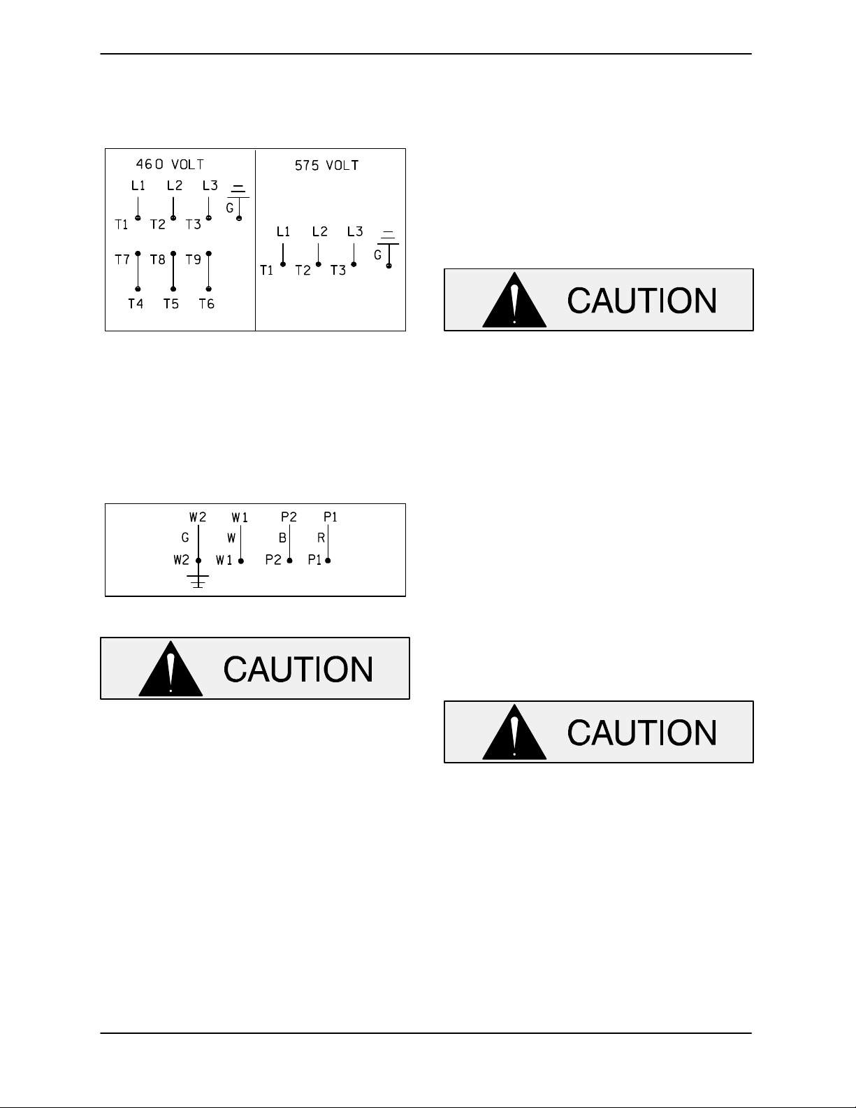
Refer to Figures B-1 and connect the pump motor
cable to the control box.
Figure B-1. Three Phase Power
Cable Connections
Control leads P1 and P2 provide the motor with
thermal protection. Control leads W1 and W2 pro
vide the motor with moisture protection. Refer to
Figure B-3 and connect the pump control cable to
the control box.
Liquid Level Devices
Optional controls available from Gorman‐Rupp
may provide a means to automatically regulate the
liquid level. These control boxes may be con
nected to the following sensing devices which per
form either filling or dewatering functions (see Fi
gure B-3).
The internal wiring of the sensing devices
are different for filling and dewatering func
tions. Be sure to follow the instructions in
cluded with the option before making con
nections.
S Diaphragm Type: two fixed‐position sen
sors (upper and lower) each contain a dia
phragm which flexes with changes in liquid
level, thus activating an enclosed miniature
switch.
Figure B-2. Control Cable Connections
The thermal protection contacts will auto
matically reclose when the motor cools to
the established safe operating tempera
ture. Whenever automatic restarting is not
desirable, connect only to controls which
are wired for manual restart.
Refer to the appropriate wiring diagram accompa
nying the control box when making electrical con
nections.
S Bulb (Float) Type: a bulb raises or lowers
(floats) with the liquid level, thus activating
an enclosed miniature switch.
Other types of liquid level devices may also be
used. Consult the factory for the liquid level device
best suited for your application.
Liquid level devices must be positioned far
enough to allow 6 minutes between starts.
If the pump motor cycles more than 10
starts per hour, it will over‐heat, resulting in
damage to the motor windings or control
box components.
PAGE B - 4 INSTALLATION
Page 13
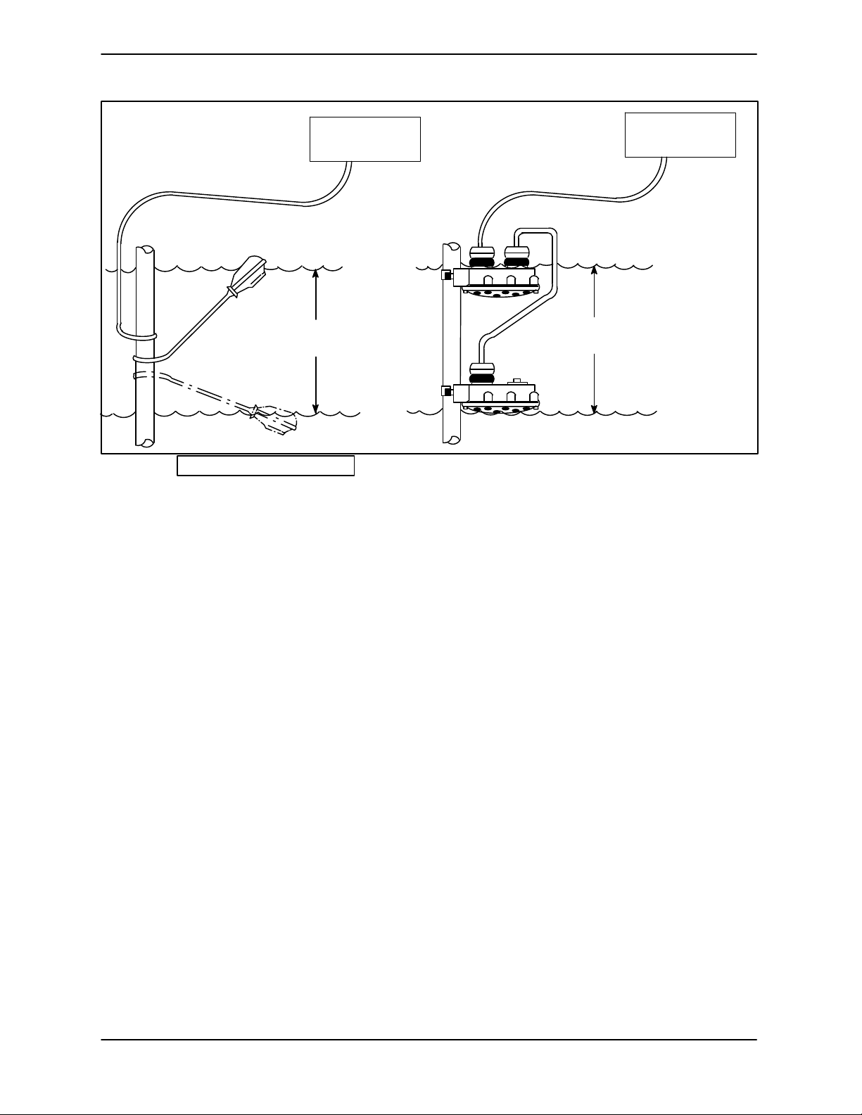
SF SERIES OM-06460
PUMP
CONTROL BOX
TO LEVEL CONTROL CIRCUIT
IN MAIN CONTROL
BOX
LIQUID LEVEL
RANGE
OFF
DEWATERING
ON (FILLING)
BULB (FLOAT TYPE)
Figure B-3. Liquid Level Devices
TO LEVEL CONTROL CIRCUIT
IN MAIN CONTROL
BOX
LIQUID LEVEL
RANGE
DEWATERING
ON (FILLING)
DIAPHRAGM TYPE
PUMP
CONTROL BOX
OFF
INSTALLATION
PAGE B - 5
Page 14
SF SERIES OM-06460
OPERATION - SECTION C
GENERAL INFORMATION
Review all SAFETY information in Section A.
This pump is designed to handle most
non‐volatile, non‐flammable liquids. Do
not attempt to pump any liquids for
which your pump is not approved, or
which may damage the pump or endan
ger personnel as a result of pump fail
ure. Consult the factory for specific ap
plication data.
Follow the instructions on all tags, labels and de
cals attached to the pump.
Pump Performance
pendent upon the quality and performance
of the electrical controls, the pump warran
ty is valid only when controls have been
specified or provided by The Gorman‐
Rupp Company.
In the performance curve which follows, perform
ance is based on 70_F (21_C) clear water at sea
level. The performance of your pump may be differ
ent due to such factors as viscosity, specific grav
ity, elevation, temperature and impeller trim.
NOTE
The curve applies to standard production models.
If your pump serial number is followed by an “N”,
your pump is not a standard production model.
Contact the Gorman‐Rupp Company to verify per
formance.
Since operation of the pump motor is de
PAGE C - 1OPERATION
Page 15

OM-06460 SF SERIES
SF4B 460/575V 3P PERFORMANCE CURVE
PAGE C - 2 OPERATION
Page 16

SF SERIES OM-06460
Control Box
Control boxes are available as optional equipment
from the factory. The control boxes contain con
trols for starting and stopping the pump, and pro
vide overload protection for the pump motor. The
pump control may be equipped with an optional
automatic liquid level sensing device, in which
case those circuits are also contained within the
control box.
Since operation of the pump motor is dependent
upon the quality and performance of the electrical
controls, the pump warranty is valid only when
controls have been specified or provided by The
Gorman‐Rupp Company.
The pump motor and control box are not
designed to be explosion‐proof. Do not
operate in an explosive atmosphere.
Any control box used to operate the
pump must be approved by the Gor
man‐Rupp Company for the application.
Improper location of a non‐explosion
proof control box could result in de
struction of equipment, injury or death
to personnel.
See the operating instructions furnished with the
control box, and with other optional accessories
and controls, before attempting to start the pump.
PUMP OPERATION
Liquid Temperature and Overheating.
2. Lock out the power to the control
panel to ensure that the pump will
remain inoperative.
3. Allow the pump to completely cool
if overheated.
4. Close the discharge valve (if
used).
5. Refer to instructions in this manual
before restarting the pump.
Overheating can occur if the pump is misapplied;
if it is started more than 10 times within one hour;
if the temperature of the liquid being pumped ex
ceeds the temperature for which the pump was de
signed, if the control box fails to provide overload
or thermal protection, or if the pump is operated
against a closed discharge valve for an extended
period of time.
Do not start the pump more than 10 times
per hour. If the motor does not cool be
tween starts it will overheat, resulting in
damage to the motor windings.
Approach the pump cautiously after it
has been running. Although the motor is
cooled by the liquid being pumped, nor
mal operating temperatures can be high
enough to cause burns. The tempera
ture will be especially high if operated
against a closed discharge valve. Never
operate against a closed discharge
valve for long periods of time.
Overheated pumps can cause severe
burns and injury. If the pump becomes
overheated:
1. Stop the pump immediately.
If overheating does occur, stop the pump immedi
ately and allow it to cool before servicing it. Ap
proach any overheated pump cautiously.
Overheated pumps can cause severe
PAGE C - 3OPERATION
Page 17

OM-06460 SF SERIES
burns and injuries. If overheating of the
pump occurs:
1. Stop the pump immediately.
2. Ventilate the area.
3. Allow the pump to completely cool.
4. Check the temperature before ser
vicing.
5. Vent the pump slowly and cau
tiously
6. Refer to instructions in this manual
before restarting the pump.
Impeller Rotation
Check impeller rotation as follows before operation
to ensure that the impeller is rotating in the correct
direction.
While checking impeller rotation, secure
the pump to prevent the power cable from
coiling.
ry or death. Make certain that incoming
power is off and locked out before inter
changing motor leads.
DIRECTION OF
KICKBACK
AT STARTUP
Figure C-1. Checking Pump Rotation
Suspend the pump from the lifting device fitted on
the pump. Apply power briefly and note the direc
tion of pump kickback. As viewed from the top, the
pump should kick in a counterclockwise direc
tion; this will indicate that impeller rotation is cor
rect.
If the pump kicks in a clockwise direction, impeller
rotation is incorrect. If the pump is powered by a
three‐phase motor, have a qualified electrician in
terchange the control box connections of any two
pump motor power leads. Re‐check pump kick
back; it should now be in a counterclockwise direc
tion.
If rotation is incorrect on a single‐phase motor, con
tact the factory before installing the pump.
The electrical power used to operate
this pump is high enough to cause inju
STARTING, STOPPING, AND
OPERATIONAL CHECKS
Starting
Do not attempt to operate the pump until
impeller rotation has been checked; im
proper rotation will affect pump perform
ance and may damage the pump.
Follow the instructions accompanying the control
box, start the pump, and run any recommended
checks.
Do not start the pump more than 10 times
per hour. If the pump motor does not cool
PAGE C - 4 OPERATION
Page 18

SF SERIES OM-06460
between starts, it will over‐heat, resulting in
damage to the motor windings.
Stopping
Follow the instructions accompanying the control
box for stopping the pump.
The integral thermal overload device
will shut off the motor if the temperature
rises above design limits. When the
pump cools and the temperature falls
below these limits, the motor will restart
automatically. To avoid the hazards of
an unexpected motor start‐up, do not at
tempt to handle or service the pump un
less all power to the motor has been
shut off and locked out at the control
box; otherwise, serious personal injury
could result.
During motor shutoff by the thermal
overload device, control box circuits re
main live. Do not attempt to service any
control box components unless incom
ing power has been shut off.
To avoid serious damage to the pump,
check for unusual noises or excessive vi
bration while the pump is running. If noise
or vibration is excessive, stop operation
and refer to the troubleshooting chart in the
maintenance and repair manual.
The suction inlet or impeller may become clogged
with debris. In some cases, stopping the pump
momentarily may backflush this blockage. If back
flushing does not clear the debris, remove the
pump from the sump or wet well and clear manu
ally.
Never introduce air or steam pressure
into the pump casing to remove a block
age. This could result in personal injury
or damage to the equipment. If back
flushing is absolutely necessary, limit
liquid pressure input to 50% of the maxi
mum permissible operating pressure
shown in the pump performance curve.
To stop the pump, turn the control handle OFF,
thereby opening the circuit breakers. This does
not terminate incoming power through the field
wiring connected to the control box.
After stopping the pump, be sure to perform all re
quired maintenance and preservation procedures.
Operational Checks
To detect minor problems, check the pump for
proper operation when it is first started, and at peri
odic intervals during operation.
Check the pump for overheating. Overheating can
occur if the pump is misapplied, required to start
repeatedly, if the control box fails to provide over
load or thermal protection, or if the pump is oper
ated against a closed discharge valve for an ex
tended period of time.
Do not start the pump more than 10 times
per hour. If the motor does not cool be
tween starts it will overheat, resulting in
damage to the motor windings.
PAGE C - 5OPERATION
Page 19

OM-06460 SF SERIES
Check the oil level(s) as indicated in the following
LUBRICATION section.
COLD WEATHER PRESERVATION
Do not attempt to thaw the pump by us
ing a torch or other source of flame. This
could damage gaskets, O‐rings or heat
the oil in the seal housing above critical
temperatures, causing the pump to rup
ture or explode.
The pump will not freeze as long as the casing is
submerged in liquid. If the casing is not sub
merged, or if the liquid begins to freeze, remove the
pump from the sump or wet well and dry it thor
oughly. Run the pump for two or three minutes to
dry the inner walls.
If the pump does freeze while it is out of the liquid,
submerge it until thawed; if the liquid is near freez
ing, the pump must be submerged for an extended
period of time. Check thawing by starting the pump
and checking that the shaft rotates freely. If the
pump remains frozen, allow additional thawing
time before attempting to restart.
If submerging does not thaw the pump, move it
into a warm area until completely thawed.
On a new pump, check the oil level in the seal cav
ity before initial startup, and drain and replace the
oil after the first 200 hours of operation. Following
this, check the oil level in the seal cavity after the
first two weeks of operation, and every month
thereafter.
Before installing or removing the lubrication plugs,
always clean the area around the plugs to prevent
contamination.
Draining Oil
Refer to the Parts List in Maintenance and Repair
- Section E for drain plug location.
Lay the pump on its side with one of the pipe plugs
(7) facing up. Clean any dirt from around the plug.
Remove the plug slowly to release any pressure
and install a short 3/8‐inch NPT nipple in the hole.
Roll the pump and drain the seal oil into a clean
container.
Condition Of Oil
Check the condition of the oil drained from the
pump. Clear oil indicates that the pump seal(s) are
functioning properly. If the oil is milky or contains
a small amount of water, it must be changed.
If the oil contains a large amount of water, it must
be changed, and the seal(s) must be checked be
fore the pump is put back in operation (Mainte
nance and Repair - Section E).
Adding Oil
LUBRICATION
Refer to Maintenance and Repair - Section E for
the oil capacity for filling the seal cavity in your
pump.
The grade of lubricant used is critical to the opera
Do not remove plates, covers, gauges,
pipe plugs or fittings from an over
heated pump. Vapor pressure within the
pump can cause parts being disen
tion of this pump. Use premium quality submers
ible pump oil as specified in Table E-2 in Mainte
nance and Repair - Section E. Oil must be stored
in a clean, tightly closed container in a reasonably
dry environment.
gaged to be ejected with great force. Al
low the pump to completely cool before
servicing.
PAGE C - 6 OPERATION
When lubricating the seal cavity, position the pump
vertically after draining the oil as indicated above
Page 20

SF SERIES OM-06460
in Draining Oil. Add premium quality submersible
pump oil through the fill plug hole until the oil is lev
el with the bottom of the plug hole.
Install and tighten the fill plug.
PAGE C - 7OPERATION
Page 21

SF SERIES OM-06460
TROUBLESHOOTING - SECTION D
Review all SAFETY information in Section A.
NOTE
Many of the probable remedies listed in the TROU
BLESHOOTING CHART require use of electrical
test instruments; for specific procedures, see
ELECTRICAL TESTING at the end of the chart.
TROUBLESHOOTING CHART
TROUBLE POSSIBLE CAUSE PROBABLE REMEDY
PUMP FAILS TO
START, OVERLOAD
UNIT NOT TRIPPED
(MANUAL MODE).
PUMP FAILS TO
START, OVERLOAD
UNIT NOT TRIPPED
(AUTOMATIC
MODE).
Power source incompatible with con
trol box.
No voltage at line side of circuit
breaker.
Open circuit in motor windings or
power cable.
Defective motor power cable. Replace cable.
Defective motor. Check for and replace defective mo
Liquid level device or control circuits
improperly connected to main con
trol box.
Level sensing device(s) improperly
positioned.
Level sensing device(s) fouled with
mud or foreign material.
Float type sensing device(s) tangled
or obstructed.
Defective liquid level sensing de
vice(s) or control panel.
Correct power source.
Check power source for blown fuse,
open circuit breaker, broken lead or
loose connections.
Check continuity.
tor components.
Check wiring diagrams: cor
rect or tighten connections.
Position device(s) at proper
level.
Clean sensing device(s).
Check installation for free
movement of float.
Repair or replace defective unit(s).
OVERLOAD UNIT
TRIPS
TROUBLESHOOTING
Low or high voltage, or excessive
voltage drop between pump and
control box.
Defective insulation in motor wind
ings or power cable; defective wind
ings.
Impeller jammed due to debris or in
sufficient clearance.
Bearings frozen. Disassemble pump and check bear
Measure voltage at control box.
Check that wiring is correct type,
size, and length (see Field Wiring
Connection, Section B).
Check insulation resistance; check
continuity.
Disassemble pump and check im
peller.
ings.
PAGE D - 1
Page 22

OM-06460 SF SERIES
TROUBLESHOOTING CHART (cont'd)
TROUBLE POSSIBLE CAUSE PROBABLE REMEDY
MOTOR RUNS, BUT
PUMP FAILS TO
DELIVER RATED
DISCHARGE.
Discharge head too high. Reduce discharge head or install
staging adaptor and additional
pump.
Low or incorrect voltage. Measure control box voltage, both
when pump is running and when
shut off.
Discharge throttling valve partially
closed; check valve installed improp
erly.
Discharge line clogged or restricted;
hose kinked.
Liquid being pumped too thick. Dilute liquid if possible.
Strainer screen or impeller clogged. Clear clog(s). Stop pump; back flow
Insufficient liquid in sump or tank. Stop pump until liquid level rises.
Worn impeller vanes. Check impeller (see PUMP END
Pump running backwards. Check direction of rotation. If incor
Open discharge valve fully; check
piping installation.
Check discharge lines; straighten
hose.
may flush away debris.
REASSEMBLY in Maintenance
and Repair, Section E).
rect, interchange any two motor
leads at the control box (3 phase
models, see Pump Rotation, Sec
tion C).
PUMP RUNS WITH
EXCESSIVE NOISE
OR VIBRATION
Pumping entrained air. Check liquid level in sump; check
position of pump and liquid level
sensing device(s).
Damaged or unbalanced impeller. Replace impeller.
Discharge piping not properly sup
ported.
Impeller jammed or loose. Check impeller.
Motor shaft or bearings defective. Disassemble pump and check mo
Pump is cavitating. Reduce discharge head or restrict
Check piping installation.
tor and bearings.
flow on low head applications.
PAGE D - 2
TROUBLESHOOTING
Page 23

SF SERIES OM-06460
ELECTRICAL TESTING
Make the electrical checks which follow to deter
mine if pump malfunctions are being caused by
problems in the motor or in the motor cable.
Test Equipment
A volt/amp/ohmmeter and megohmmeter of ade
quate range and quality are required to conduct
the electrical tests which follow.
Equipment Use
Ammeter To check AC Voltage
and current (amperage)
Ohmeter To measure resistance
(ohms) to ground
3. The pump submerged and running under
full load.
The voltage measured under each condition
must be the same.
b. If voltage is balanced when the pump is off but
is imbalanced when the pump is running,
thoroughly check the power source, all inter
connecting cables, and the pump motor to
isolate the defect.
c. Use an Amprobe or equivalent instrument to
measure the current draw (amperage) of
each phase while the pump is running under
full load, and with no load. In each condition,
the amperage readings for all three phases
must match as closely as can be measured.
Normal amperage values are listed in Table
B-1 in INSTALLATION; these values apply
only when the voltage at the site is the normal
voltage listed.
Refer to the wiring diagram(s) accompany
ing the motor and control box before re
connecting any electrical leads which have
been disconnected. Connections to the
wrong terminals may damage the motor
and/or control devices.
Voltage Imbalance
Use a voltmeter to read each phase of the incom
ing 3 phase power. Each phase must balance with
the other two as closely as can be measured with a
commercial instrument. If the phases are out of
balance, contact your power company. If the
phases are balanced, check out the motor as de
scribed in the following steps:
a. Use a voltmeter, Amprobe, or equivalent in
strument to read the voltage of incoming
power lines 1 and 2, 2 and 3, and 1 and 3 at the
control box. Voltage must match as closely as
can be measured. If possible, measure the
voltage at the control box with:
1. The pump shut off.
2. The pump running in air.
Power Cable Continuity
Set the megohmmeter at R x 1 scale and zero‐ba
lance it. Test as follows:
a. Shut off incoming power to the control box,
and disconnect the motor power cable leads.
Connect the megohmmeter test leads to any
two cable leads, and note the megohmmeter
reading. A high resistance reading indicates
an open or broken circuit in the power cable or
motor windings, or a bad connection between
the motor and cable.
b. Repeat Step a. with each set of leads. The
three readings should be as close as can be
measured.
c. If readings indicate that continuity problems
exist in the motor or power cable, the motor
and/or terminal housing assembly must be re
paired before putting the pump into service.
Insulation Resistance
Set the megohmmeter at R x 100, and zero‐ba
lance it. Test as follows:
a. Shut off incoming power to the control box,
and disconnect the motor power cable leads.
Connect one megohmmeter test lead to the
TROUBLESHOOTING
PAGE D - 3
Page 24

OM-06460 SF SERIES
motor cable green/yellow ground lead. Touch
the other test lead to each of the motor cable
leads in turn. Note the readings.
b. Readings will indicate resistance values in
both the power cable and motor windings.If
resistance reads infinity (1), insulation is
good. If resistance reads between infinity (1),
and 1 megohm, insulation is acceptable but
should be rechecked regularly. If resistance
reads less than 1 megohm, insulation should
be checked more closely and frequently.
c. If readings indicate that a ground exists, test
the stator and motor power cable separately.
Replace as required.
PAGE D - 4
TROUBLESHOOTING
Page 25

PUMP MAINTENANCE AND REPAIR - SECTION E
OM-06460SF SERIES
GENERAL INFORMATION
Review all SAFETY information in Section A.
Do not attempt to service the pump as
sembly unless all power to the motor
has been shut off at the control box;
otherwise, injury or death could result.
Use a lifting device with sufficient ca
pacity. If slings or chains are used to
move the pump or components, make
sure that the load is balanced; other
wise serious personal injury or death
could result.
The maintenance and repair instructions in this
manual are keyed to the illustrations, Figures E-1
and E-2, and the corresponding parts lists.
Select a suitable location, preferably indoors, to
perform required maintenance. All work must be
performed by qualified personnel.
Check TROUBLESHOOTING, Section B to deter
mine causes and remedies of pump problems.
Disassemble the pump only as far as required.
Lifting
Pump unit weights will vary depending on the
mounting and drive provided. Check the shipping
tag on the unit packaging for the actual weight, and
use lifting equipment with appropriate capacity.
Drain the pump and remove all customer‐installed
equipment such as suction and discharge hoses
or piping before attempting to lift existing, installed
units.
PAGE E - 1MAINTENANCE AND REPAIR
Page 26

PARTS PAGE
SF SERIESOM-06460
ILLUSTRATION
Figure E-1. SF4B Pump Model Assembly
MAINTENANCE AND REPAIRPAGE E - 2
Page 27

OM-06460SF SERIES
SF4B Pump Model Assembly
Parts List
(From S/N 1504502 Up)
If your pump serial number is followed by an “N”, your pump is NOT a standard production model. Contact
the Gorman‐Rupp Company to verify part numbers.
ITEM
PART NAME PART
NO.
1 PUMP CASING
-ANSI 38218-309 11010 1
-DIN 38218-313 11010 1
2 IMPELLER SEE NOTE
3 IMPELLER WASHER 31514-017 17000 1
4 SOCKET HD CAPSCREW MBD1020 17000 1
5 WEAR RING 38691-368 11010 1
6 O‐RING 25152-277 --- 1
7 LOCK WASHER MJ12 17000 14
8 ADJUSTING SCREW MB1235 17000 4
8A HEX HD CAPSCREW MB1235 17000 4
9 SUCTION HEAD
-ANSI 38246-619 10000 1
-DIN 38246-620 10000 1
10 O‐RING 25152-276 --- 1
11 HEX HD CAPSCREW MB1245 17000 8
12 NAME PLATE 38814-074 17000 1
13 DRIVE SCREW BM#04-03 17000 4
14 MOTOR ASSY
-460/3 47111-824 --- 1
-575/3 47111-825 --- 1
15 10 METER TERMINAL HOUSING ASSY
12 METER TERMINAL HOUSING ASSY
15 METER TERMINAL HOUSING ASSY
25 METER TERMINAL HOUSING ASSY
35 METER TERMINAL HOUSING ASSY
50 METER TERMINAL HOUSING ASSY
16 LOCK WASHER MJ10 17000 4
17 HEX NUT MD10 17000 4
18 HEX HD CAPSCREW MB1235 17000 2
19 LIFTING BAIL ASSY 44713-048 17040 1
20 JAM NUT MAT12 17000 4
21 SEAL PLATE 38272-536 10000 1
22 O‐RING 25152-379 --- 1
23 FLAT HD CAPSCREW MF0520 17000 4
24 SHAFT SLEEVE O‐RING 25154-022 --- 1
25 SHAFT SLEEVE 31441-030 1706H 1
NUMBER
47367-714 --- 1
47367-716 --- 1
47367-718 --- 1
47367-720 --- 1
47367-722 --- 1
47367-724 --- 1
MAT'L
CODE
QTY ITEM
NO.
26 SEAL ASSY 25285-856 --- 1
27 SPRING RETAINER 31161-042 17000 1
28 IMP ADJ SHIM SET 37J 17090 1
29 PIPE PLUG P04 17000 2
NOT SHOWN:
OPTIONAL:
PART NAME PART
NUMBER
INFINITY DECAL 38811-435 --- 1
G‐R DECAL GR-03 --- 1
TERM HOUSING O‐RING 25154-153 --- REF
ANSI SLIDE RAIL VERSION
GUIDE SHOE KIT 48156-559 --- 1
-GUIDE SHOE SEAL 31513-054 19020 1
SLIDE RAIL KIT 48156-024 --- 1
ALIGNMENT KIT 48786-551 --- 1
BASEPLATE KIT
-SHORT 48156-603 --- 1
-LONG 48156-604 --- 1
LIFTING CABLE KIT
-36' 48151-502 --- 1
-50' 48151-504 --- 1
DIN SLIDE RAIL VERSION
GUIDE SHOE KIT 48156-560 --- 1
-GUIDE SHOE SEAL 31513-054 19020 1
SLIDE RAIL KIT CONSULT FACTORY 1
ALIGNMENT KIT 48786-552 --- 1
BASEPLATE KIT
-SHORT CONSULT FACTORY 1
-LONG CONSULT FACTORY 1
LIFTING CABLE KIT
-36' 48151-502 --- 1
-50' 48151-504 --- 1
ANSI TRASH VERSION
STAND KIT 48786-209 --- 1
DISCH ELBOW KIT 48135-102 --- 1
INCREASER KIT 48135-502 --- 1
DIN TRASH VERSION
STAND KIT 48786-213 --- 1
DISCH ELBOW KIT 48135-106 --- 1
LIQUID LEVEL DEVICES:
DIAPHRAGM TYPE GRP48-03 --- 1
GRP48-06 --- 1
FLOAT TYPE 27471-180 --- 1
120V LIQUID LEVEL
CONTROL RELAY 27521-321 --- 1
MAT'L
CODE
QTY
INDICATES PARTS RECOMMENDED FOR STOCK
NOTE: FOR IMPELLER P/N, CONTACT THE FACTORY WITH PUMP MODEL, S/N AND IMPELLER DIAMETER (FROM NAMEPLATE)
PAGE E - 3MAINTENANCE AND REPAIR
Page 28

ILLUSTRATION
SF SERIESOM-06460
Figure E-2. 47111-824 and -825 Motor Assemblies
MAINTENANCE AND REPAIRPAGE E - 4
Page 29

47111-824 and -825 Motor Assemblies
Parts List
OM-06460SF SERIES
ITEM
NO.
1 MOTOR SUBASSEMBLY
2 BEARING 23257-012 --- 1
3 ROTOR/SHAFT ASSY 47112-088 --- 1
4 BEVELED SNAP RING 24121-555 --- 1
5 BEARING 23431-310 --- 1
6 O‐RING 25152-279 --- 1
7 PIPE PLUG P08 17000 2
8 INTERMEDIATE 38261-038 10000 1
9
10 SNAP RING S245 --- 1
11 LOCK WASHER MJ12 17000 8
12 HEX HD CAPSCREW MB1230 17000 8
13 MOISTURE DETECTOR 27479-009 --- 1
14 FEMALE TERMINAL 27236-054 --- 1
15 MALE TERMINAL 27236-454 --- 1
16 IMPELLER KEY MNR100820 17000 1
17 36” 18 AWG WIRE 18147-104 --- 1
NOT SHOWN (SUPPLIED WITH MOTOR SUBASSEMBLY):
INDICATES PARTS RECOMMENDED FOR STOCK
PART NAME
-460/3 47111-840 --- 1
--MOTOR HOUSING 38311-215 10000 1
--STATOR 47113-097 --- 1
--TERMINAL HOUSING STUD MC1042 17000 4
--VOLTAGE TAG 38816-460 --- 1
--ROTATION DECAL 38815-027 --- 1
-575/3 47111-841 --- 1
--MOTOR HOUSING 38311-215 10000 1
--STATOR 47113-098 --- 1
--TERMINAL HOUSING STUD MC1042 17000 4
--VOLTAGE TAG 38816-128 --- 1
--ROTATION DECAL 38815-027 --- 1
SEAL ASSY S1934 --- 1
WIRE CONNECTOR S1718 --- 3
POWER LEAD CONTACTS:
-208‐230/460/3 27216-003 --- 3
-575/3 27216-005 --- 3
POWER LEAD CONTACT HOUSINGS:
-BLACK 27216-034 --- 1
-WHITE 27216-035 --- 1
-RED 27216-036 --- 1
CONTROL LEAD CONTACT 27216-002 --- 3
CONTROL LEAD CONTACT HOUSINGS:
-ORANGE 27216-031 --- 1
-BLUE 27216-032 --- 1
-BROWN 27216-033 --- 1
PART
NUMBER
MAT'L
CODE
QTY
PAGE E - 5MAINTENANCE AND REPAIR
Page 30

SF SERIESOM-06460
PUMP AND SEAL DISASSEMBLY AND REASSEMBLY
Review all SAFETY information in Section A.
This pump requires little service due to its rugged,
minimum‐maintenance design. However, if it be
comes necessary to inspect or replace the wearing
parts, follow these instructions, which are keyed to
the illustrations (see Figures E-1 and E-2) and
the corresponding parts lists.
This manual will alert personnel to known proce
dures which require special attention, to those
which could damage equipment, and to those
which could be dangerous to personnel. However,
this manual cannot possibly anticipate and provide
detailed precautions for every situation that might
occur during maintenance of the unit. Therefore, it
is the responsibility of the owner/maintenance per
sonnel to ensure that only safe, established main
tenance procedures are used, and that any proce
dures not addressed in this manual are performed
only after establishing that neither personal safety
nor pump integrity are compromised by such prac
tices.
Do not attempt to service the pump as
sembly unless all power to the motor
has been shut off at the control box;
otherwise, injury or death could result.
Select a suitable location, preferably indoors, to
perform required maintenance. All work must be
performed by qualified personnel.
Check the chart in TROUBLESHOOTING, Section
D of this manual, to determine the nature of the
pump problem. If the problem is mechanical in na
ture, such as worn pump parts, seal replacement,
lubrication, etc., refer to PUMP END DISASSEM
BLY for instructions.
If the problem is electrical, complete disassembly
may not be required. Refer to Electrical Testing in
TROUBLESHOOTING, Section D, and have a
qualified electrician check the control box, cable
and terminal housing. If the problem is determined
to be in the cable(s) or terminal housing, see MO
TOR DISASSEMBLY for terminal housing replace
ment. If the problem is determined to be in the mo
tor, proceed with PUMP END DISASSEMBLY, fol
lowed by MOTOR DISASSEMBLY.
The electrical power used to operate
this pump is high enough to cause inju
ry or death. Make certain that the control
handle on the control box is in the off po
sition and locked out, or that the power
supply to the control box has been
otherwise cut off and locked out, before
attempting to open or service the pump
assembly. Tag electrical circuits to pre
vent accidental start‐up.
Use a lifting device with sufficient ca
pacity. If slings or chains are used to
move the pump or components, make
sure that the load is balanced; other
wise serious personal injury or death
could result.
If this pump is used to handle sewage,
take necessary precautions during
maintenance and repair to prevent per
sonal contamination which could result
in illness.
Carefully inspect any O‐rings before removal and
cleaning to determine if a proper seal and com
pression existed prior to disassembly. If sealing
was faulty or questionable, the cause must be de
termined and corrected before reassembly. All O‐
rings must be replaced if disturbed.
PUMP END DISASSEMBLY
Preparing Pump for Disassembly
Use the hoisting bail to remove the pump from the
wet well or sump. If installed in a trash application,
remove the discharge piping and move the pump
to a suitable location for disassembly.
MAINTENANCE AND REPAIRPAGE E - 6
Page 31

Do not attempt to lift the pump by the
motor power cable or the piping. Attach
proper lifting equipment to the lifting
device fitted to the pump. If chains or
cable are wrapped around the pump to
lift it, make certain that they are posi
tioned so as not to damage the pump,
and so that the load will be balanced.
If installed in a slide rail application, it is not neces
sary to remove the guide shoe for most pump
maintenance procedures. If removal of the guide
shoe is desired, disengage the hardware securing
the guide shoe to the pump casing and remove the
guide shoe and guide shoe seal.
If installed in a trash application, it is not necessary
to remove the optional discharge elbow for most
pump maintenance procedures. If removal of the
discharge elbow is desired, disengage the hard
ware securing the elbow to the pump casing and
remove the elbow and gasket.
OM-06460SF SERIES
Pump Casing Removal
(Figure E-1)
Position the pump assembly on a flat surface and
use the lifting bail and lifting device to support the
pump in a vertical position. Remove the hardware
(7 and 11) securing the motor assembly (14) to the
pump casing (1).
Using the lifting device, raise the motor assembly
out of the pump casing. It may be necessary to tap
around the circumference of the pump casing with
a soft‐faced mallet to break the seal between the
casing and motor. When the motor is free of the
pump casing, position the motor and remaining
pump end components horizontally on a flat sur
face for further disassembly. Chock the pump to
prevent rolling when positioned horizontally.
Remove the O‐ring (22) from the outer shoulder of
the seal plate (21).
Draining Oil From Seal Cavity
(Figure E-2)
The seal cavity oil must be drained to prevent the
oil from escaping as the impeller is removed.
If the pump is equipped with a trash stand, disen
gage the hardware securing the pump to the stan
before proceeding with pump disassembly.
Suction Head and Wear Ring Removal
(Figure E-1)
Position the pump horizontally on a flat work sur
face and remove the hardware (7 and 8A) securing
the suction head (9) to the pump casing (1).
Use a pair of suitable tools to pry the suction head
and assembled wear ring (5) out of the pump cas
ing.
Inspect the wear ring for excessive wear or scoring.
If replacement is required, install two M12 x 1.75 x
76 mm long capscrews (not supplied) in the
tapped holes in the suction head. Turn the screws
evenly in an alternating sequence to press the
wear ring out of the suction head.
Let the pump cool before removing the
seal cavity drain plug. Pressure built up
within a hot pump could cause the oil to
spray out when the plug is removed. Re
move the plug slowly and permit pressure
to vent to atmosphere.
Lay the pump on its side with one of the pipe plugs
(7) facing up. Clean any dirt from around the plug.
Remove the plug slowly to release any pressure
and install a short 3/8‐inch NPT nipple in the hole.
Roll the pump and drain the seal oil into a clean
container. Inspect the oil for water, dirt, or cloudy
condition which could indicate lower seal failure or
poor O‐ring seal.
Impeller Removal
(Figure E-1)
Wedge a soft metal rod between the impeller vanes
to prevent impeller rotation and use a hex key to re
PAGE E - 7MAINTENANCE AND REPAIR
Page 32

SF SERIESOM-06460
move the impeller screw (4). Remove the impeller
washer (3). Remove the metal rod from between
the vanes of the impeller.
NOTE
An alternate method of removing the impeller screw
is to immobilize the impeller using a strap wrench.
A hex key used in conjunction with an impact
wrench can also be used to remove the impeller
screw.
To remove the impeller, use two thin‐bladed screw
drivers positioned 180_ apart to pry on the back of
the impeller and “walk” the impeller off the shaft.
Use increasingly larger screwdrivers (or wedges)
as necessary. After the impeller comes free of the
shaft, retain the impeller key (16, Figure E-2).
Remove the impeller adjusting shims (28). Tie and
tag the shims for ease of reassembly.
If no further disassembly is required, proceed to
the appropriate areas in PUMP END REASSEMB
LY.
Lower Seal Removal
(Figures E-1 and E-3)
Carefully remove the spring retainer (27) and seal
spring. Slide the shaft sleeve (18) and rotating por
tion of the seal off the shaft as a unit.
Apply oil to the sleeve and work it up under the rub
ber bellows. Slide the rotating portion of the seal off
the shaft sleeve.
Work a pair of stiff wires with hooked ends between
the rotor shaft and the stationary seat and pull the
stationary seat and O‐ring out of the seal plate (15).
NOTE
An alternate method of removing the stationary ele
ment is to remove the screws (23) securing the seal
plate (21) to the motor assembly (14). Pry the as
sembled seal plate and stationary element off the
shoulder of the intermediate (8, Figure E-2). Re
move the O‐ring (10) and press the stationary ele
ment and seat out of the seal plate from the back
side.
Remove the seal sleeve O‐ring (24) from the rotor
shaft.
If no further disassembly is required, proceed to
the appropriate areas in PUMP END REASSEMB
LY.
Upper Seal Removal
(Figures E-2 and E-3)
With the pump end and lower seal removed, se
cure the pump in an inverted position for further
disassembly.
Remove the seal plate (21, Figure E-1) as de
scribed above in Lower Seal Removal.
Remove the seal retaining ring (10) using snap ring
pliers. Use caution when removing the retaining
ring; tension on the seal spring will be released.
Remove the spring centering washer and seal
spring.
Lubricate the seal area of the rotor shaft (3) and
work oil up under the bellows. Remove the hard
ware (11 and 12) securing the intermediate (8) to
the motor subassembly (1).
Carefully pull the assembled intermediate, rotor
shaft (3) and bearings (2 and 5) out of the motor
housing until the female terminal (14) can be ac
cessed. Pull the female terminal off the male termi
nal (15) and remove the intermediate, rotor shaft
and bearings from the motor assembly. Remove
the O‐ring (6) from the intermediate shoulder.
Remove the snap ring (4) from the groove in the in
termediate and pull the assembled rotor shaft and
bearings out of the intermediate. Cover the motor
assembly with a clean rag to prevent foreign mate
rial from entering the motor cavity.
With the rotor shaft and bearings removed, press
the stationary seal element and O‐ring out of the in
termediate from the back side.
If no further disassembly is required, proceed to
the appropriate areas in PUMP END REASSEMB
LY.
NOTE
Do not disassemble the motor unless it is neces
sary and a clean, well‐equipped shop is available. If
the motor housing components are to be serviced,
see MOTOR DISASSEMBLY in this section. Do not
reassemble the pump end components at this time.
MAINTENANCE AND REPAIRPAGE E - 8
Page 33

OM-06460SF SERIES
PUMP END REASSEMBLY
NOTE
Reuse of old O‐rings or shaft seal parts will result in
premature leakage or reduced pump performance.
It is strongly recommended that new O‐rings and
shaft seal assemblies be used during reassembly
(see the parts lists for numbers).
Cleaning and Inspection of Pump Parts
(Figures E-1 and E-2)
Carefully inspect any O‐rings before removal and
cleaning to determine if a proper seal existed prior
to disassembly. If sealing was faulty or question
able, the cause must be determined and corrected
before reassembly. Replace any parts as required.
Thoroughly clean all reuseable parts with a soft
cloth soaked in cleaning solvent. Remove all O‐
rings and clean the sealing surfaces.
precautions printed on solvent contain
ers.
Inspect the rotor shaft (3, Figure E-2) for dam
aged threads, scoring, or nicks. Remove nicks and
burrs with a fine file or hand honing stone to restore
original contours. If the shaft is bent or severely
damaged, the rotor and shaft must be replaced as
an assembly (see MOTOR DISASSEMBLY).
Neither of the shaft seal assemblies should be re
used because wear patterns on the finished faces
cannot be realigned during reassembly. This could
result in premature failure. If necessary to reuse an
old seal in an emergency, carefully wash all me
tallic parts in fresh cleaning solvent and allow to dry
thoroughly.
Handle the seal parts with extreme care to prevent
damage. Be careful not to contaminate the preci
sion finished faces; even fingerprints on the faces
can shorten seal life. If necessary, clean the faces
with a non‐oil based solvent and a clean, lint‐free
tissue. Wipe lightly in a circular pattern to avoid
scratching the faces.
Most cleaning solvents are toxic and
flammable. Use them only in a well ven
tilated area free from excessive heat,
sparks, and flame. Read and follow all
Inspect the seal components for wear, scoring,
grooves, and other damage that might cause leak
age. If any components are worn, replace the com
plete seal; never mix old and new seal parts.
Install the shaft seals as illustrated in Figure E-3.
PAGE E - 9MAINTENANCE AND REPAIR
Page 34

SF SERIESOM-06460
ROTOR
SHAFT
ROTATING
ELEMENT
SPRING
SPRING
CENTERING
WASHER
STATIONARY
SEAL SEAT
BELLOWS AND
RETAINER ASSY
SHIM SET
STATIONARY
SEAL SEAT
O‐RING
BELLOWS AND
RETAINER ASSY
SEAL
RETAINING RING
SEAL PLATE
O‐RING
ROTATING
ELEMENT
SPRING
SPRING
RETAINER
Figure E-3. Upper And Lower Seal Assemblies
The seal assemblies are not designed for
operation at temperatures above 104_F
(40_C). Do not use at higher operating
temperatures.
Upper Seal Installation
(Figures E-2 and E-3)
Do not unwrap a new seal assembly until time of
installation. Cleanliness of seal components is criti
cal, especially the seal faces.
Clean the rotor shaft (3) and seal cavity area of the
intermediate (8). Be sure the area is dry and free of
lint and dirt. Check the seal bore for burrs or nicks
that might prevent a good seal. Remove them with
a fine file or emery cloth to restore original con
tours. If the shaft is bent or damaged, the complete
rotor and shaft must be replaced as an assembly.
IMPELLER
Apply a light coating of oil to the bore of the inter
mediate.
Position the intermediate with the impeller end
down on some wood blocks tall enough to allow for
installation of the rotor shaft through the intermedi
ate.
Inspect the rotor shaft (3) and bearings (2 and 5) as
indicated in Bearing and Rotor Shaft Installation
in this section and replace any parts as necessary.
Slide the assembled shaft and bearings into the in
termediate until the lower bearing seats squarely in
the intermediate bore. Secure the rotor and shaft to
the intermediate by installing the snap ring (4) in
the groove in the intermediate bore.
Install a new O‐ring (6) on the shoulder of the inter
mediate.
With the motor housing and stator positioned up
side down, carefully lower the assembled inter
mediate, rotor shaft and bearings into the motor
housing until the female terminal (14) can be se
curely attached to the male terminal (15) on the
moisture sensor.
MAINTENANCE AND REPAIRPAGE E - 10
Page 35

OM-06460SF SERIES
Position the intermediate so the holes for the
mounting hardware in the intermediate align with
those in the motor housing and press the inter
mediate into the motor housing until fully seated.
Apply “Never‐Seez” or equivalent compound on
the threads of the capscrews (12) and secure the
intermediate to the motor housing with the hard
ware (11 and 12). Torque the capscrews to 47 ft.
lbs. (6,5 m. kg.).
Subassemble the O‐ring onto the stationary seat.
Position this subassembly in the intermediate bore
with the sealing face up and cover the seal face
with a clean tissue. Use your thumbs to press the
assembly into the bore. Apply equal pressure on
opposite sides until the seat contacts the bore
shoulder. Remove the tissue and inspect the seal
face to ensure that it is clean and dry. If cleaning is
necessary, use clean tissue to wipe lightly in a cir
cular pattern.
Unpack the rotating portion of the seal. Be certain
the seal face of the rotating element is free of grit or
surface damage. Because the rotating element
may not stay in the bellows retainer when turned
upside down, place a small amount of grease at
equal spaces on the back of the element and posi
tion it in the bellows retainer. The grease should
hold the element in position until the seal is in
stalled. Assemble the drive grooves of the rotating
element into the drive lugs of the bellows retainer.
Lubricate the I.D. of the bellows with water and
slide the rotating subassembly onto the rotor shaft
until the seal faces contact.
Slide the seal spring over the shaft and bellows re
tainer and install the spring centering washer. In
stall the seal retaining ring (10). See Figure E-3 for
the proper order of seal assembly.
Lower Seal Installation
against the shaft shoulder. Use caution not to nick
or damage the O‐ring on the shaft keyway.
Position the seal plate on a clean flat surface with
the impeller side up.
Unpack the seal stationary seat and O‐ring. Apply
a light coating of oil to the seal plate bore and the
O.D. of the stationary seat O‐ring. Keep the sealing
face dry.
Position the stationary seat and O‐ring in the seal
plate bore with the sealing face up and cover the
seal face with a clean tissue. Use your thumbs to
press the assembly into the bore. Apply equal
pressure on opposite sides until the seat contacts
the bore shoulder. Remove the tissue and inspect
the seal face to ensure that it is clean and dry. If
cleaning is necessary, use clean tissue to wipe
lightly in a circular pattern.
NOTE
If the seal plate was not removed during disassem
bly, cover the stationary element with a clean tissue
and use your thumbs to press the seal stationary
seat and O‐ring into the seal plate as described
above. Remove the tissue and inspect the seal face
to ensure that it is clean and dry.
Install a new O‐ring (10) on the shoulder of the in
termediate (8, Figure E-2).
Carefully position the seal plate and stationary seal
components on the rotor shaft. Align the holes in
the seal plate for the capscrews (23) with those in
the intermediate and slide the seal plate onto the
shaft until fully seated against the intermediate. Be
careful not to damage the stationary seat already
installed in the seal plate. Apply “Neverseeze” or
equivalent compound to the threads of the caps
crews (23). Secure the seal plate to the intermedi
ate by torquing the capscrews to 3.3 ft. lbs. (637 in.
lbs. or 0,45 m. kg.).
(Figures E-1 and E-3)
Thoroughly clean the O‐ring surfaces and seal
bore of the seal plate (21). The seal bore must be
free of burrs and nicks which could damage the
seal. Inspect the seal plate for cracks, distortion, or
erosion and replace it if defective.
Lubricate the seal sleeve O‐ring (24) with light oil
and slide it onto the rotor shaft until it is seated
Unpack the rotating portion of the seal. Be certain
the seal face of the rotating element is free of grit or
surface damage. Because the rotating element
may not stay in the bellows retainer when turned
upside down, place a small amount of grease at
equal spaces on the back of the element and posi
tion it in the bellows retainer. The grease should
hold the element in position until the seal is in
stalled. Assemble the drive grooves of the rotating
element into the drive lugs of the bellows retainer.
PAGE E - 11MAINTENANCE AND REPAIR
Page 36

SF SERIESOM-06460
Lubricate the I.D. of the bellows with water and
slide the rotating subassembly over the shaft
sleeve (18) until the seal face is just flush with the
undercut end of the sleeve.
Slide the assembled shaft sleeve and rotating por
tion of the seal and onto the rotor shaft until the pol
ished faces contact. Continue to push the sleeve
through the seal until it is fully seated against the
shaft shoulder.
Install the seal spring over the bellows retainer and
install the spring retainer (27). See Figure E-3 for
proper order of seal assembly.
Impeller Installation
(Figure E-1)
Inspect the impeller (2) for cracks, broken vanes,
or wear from erosion and replace it if damaged.
Clean the threads in hole in the rotor shaft for the
impeller screw (4).
Install the same thickness of adjusting shims (28)
as previously removed. Install the impeller key (16,
Figure E-2) in the rotor shaft keyway. Align the
keyway of the impeller (2) with the shaft key and
push the impeller onto the shaft until seated firmly
against the upper impeller shim set.
A clearance of .020 to .040 inch (0,51 to 1,02 mm)
between the impeller and the seal plate is recom
mended for maximum pump efficiency. Measure
this clearance and add or remove impeller adjust
ing shims as required.
After the impeller is installed, coat the threads of
the impeller screw (4) with `Loctite Threadlocker
No. 242' or equivalent compound. Install the impel
ler washer (3) and the impeller screw. Wedge a soft
metal bar between the vanes of the impeller to pre
vent rotation and torque the impeller screw to 27 ft.
lbs. (3,7 m. kg.).
Remove the block of wood and turn the impeller to
check for free rotation.
Suction Head and Wear Ring Installation
(Figure E-1)
The suction head (9) and wear ring (5) must be
installed in the pump casing (1) before installing
the pump casing in order to set the impeller‐to‐
wear ring clearance.
If the wear ring was removed from the suction
head, position the replacement wear ring in the
suction head bore and use an arbor (or hydraulic)
press to press the wear ring into the suction head
until fully seated.
Install a new O‐ring (6) on the shoulder of the suc
tion head. Position the suction head against the
pump casing and use the hardware (7 and 8A) to
press the suction head into the pump casing.
Adjust the impeller‐to‐wear ring clearance after
installing the pump casing as described below.
Pump Casing Installation
(Figure E-1)
Before installing the pump casing, loosen the jam
nuts (20) and unscrew the capscrews (8) from the
seal plate until they no longer protrude through the
pump casing side of the seal plate.
Install a new O‐ring (15) on the shoulder of the seal
plate. Orient the pump casing (1) as shown in Fig
ure E-1 and slide it over the seal plate shoulder
until fully seated. Apply “Never‐Seez” or equivalent
compound to the capscrews (11) and use the
hardware (7 and 11) to draw the pump casing over
the shoulder of the seal plate until the wear ring just
touches the face of the impeller.
Finish the face clearance adjustment as described
below.
Impeller Face Clearance Adjustment
(Figure E-1)
A clearance of .006 to .012 inch ( to mm) between
the face of the impeller and the wear ring is recom
mended for maximum pump efficiency.
Loosen the capscrews (11) securing the pump
casing to the motor assembly. Measure the clear
ance between the impeller and wear ring. If the
clearance is too narrow, turn the screws (8) in an
alternating pattern to push the pump casing and
suction head away from the impeller until the prop
er clearance is achieved. If the clearance is too
wide, use the hardware (7 and 11) to draw the
MAINTENANCE AND REPAIRPAGE E - 12
Page 37

OM-06460SF SERIES
pump casing and suction head toward the impeller
until the proper clearance is achieved.
When the face clearance is properly set, secure the
adjusting screws (8) by tightening the jam nuts
(20) against the back of the seal plate.
Final Assembly
If installed in a slide rail application and the pump
guide shoe was removed for disassembly, install a
new guide shoe seal and secure the seal and guide
shoe to the pump casing with the previously re
moved hardware.
If installed in a trash application, secure the pump
to the trash stand with the previously removed
hardware. If the discharge elbow was removed, re
place the gasket and secure the discharge elbow
to the pump casing with the previously remove
hardware and reconnect the discharge piping.
attempting to open or service the pump
assembly. Tag electrical circuits to pre
vent accidental start‐up.
Carefully inspect any O‐rings before removal and
cleaning to determine if a proper seal and com
pression existed prior to disassembly. If sealing
was faulty or questionable, the cause must be de
termined and corrected before reassembly. Re
place any parts as required.
Hoisting Bail Removal
(Figure E-1)
The hoisting bail (19) must be removed in order to
remove the terminal housing assembly (15). To re
move the hoisting bail, disengage the hardware
(16 and 17) and separate the bail from the motor
housing.
Terminal Housing Assembly Removal
Use a suitable lifting device to reposition the pump
in the wet well or sump.
MOTOR DISASSEMBLY
Disassembly of the motor is rarely required except
to replace the motor rotor, stator or bearings. Do
not disassemble the motor unless it is necessary
and a clean, well‐equipped shop is available.
NOTE
It is recommended that a pump with a defective mo
tor be returned to Gorman‐Rupp, or to a Gorman‐
Rupp authorized Submersible Repair Center.
The electrical power used to operate
this pump is high enough to cause inju
ry or death. Make certain that the control
handle on the control box is in the off po
sition and locked out, or that the power
supply to the control box has been
otherwise cut off and locked out, before
(Figure E-1)
The terminal housing assembly (9) may be re
placed without disassembling the motor or pump
end components.
With the pump secured in an upright position, re
move the hardware (10 and 11) securing the termi
nal housing assembly to the motor assembly (6).
Carefully pull the terminal housing assembly out of
the motor housing until the power and motor cable
connections with the stator leads can be ac
cessed.
The contacts on the ends of each cable lead are se
cured in a plastic housing which mates with a cor
responding housing on each of the stator leads.
Carefully pull each of the cable lead housings apart
from its corresponding stator lead housing and re
move the terminal housing assembly from the
pump.
Further disassembly of the terminal housing as
sembly is not required. Individual parts are not sold
separately.
See Terminal Housing Assembly Installation if
no further disassembly is required.
PAGE E - 13MAINTENANCE AND REPAIR
Page 38

SF SERIESOM-06460
Rotor Shaft and Bearing Removal
(Figure E-2)
See PUMP END DISASSEMBLY, and remove all
pump end and seal components.
With the pump end disassembled and the seal cav
ity drained of oil, secure the pump in an inverted
position. Remove the hardware (11 and 12) secur
ing the intermediate (8) to the motor subassembly
(1).
Carefully pull the assembled intermediate, rotor
shaft (3) and bearings (2 and 5) out of the motor
housing until the female terminal (14) can be ac
cessed. Pull the female terminal off the male termi
nal (15) and remove the intermediate, rotor shaft
and bearings from the motor assembly. Remove
the O‐ring (6) from the intermediate shoulder.
If the moisture sensor (13) requires replacement,
unscrew it from the hole in the intermediate.
precautions printed on solvent contain
ers.
Rotate the bearings by hand to check for rough
ness or binding. If rotation is rough, replace the
bearings.
The bearing tolerances provide a tight press fit
onto the shaft and a snug slip fit into the motor
housing and intermediate bearing bores. Replace
the shaft and rotor (as an assembly), the motor
housing or intermediate if the proper bearing fit is
not achieved.
If replacement is required, use a bearing puller to
remove the upper and lower bearings from the ro
tor shaft.
If no further disassembly is required, cover the mo
tor housing with a clean, lint free cloth to avoid con
tamination by dirt or other foreign material.
Stator Removal
Remove the snap ring (4) from the groove in the in
termediate and pull the assembled rotor shaft and
bearings out of the intermediate.
To prevent damage during removal from
the shaft, it is recommended that bearings
be cleaned and inspected in place. It is
strongly recommended that the bearings
be replaced any time the shaft and rotor
assembly is removed.
Before removing the bearings from the rotor shaft,
clean and inspect the bearings in place as follows.
Clean the bearings thoroughly in fresh cleaning
solvent. Dry the bearings with filtered compressed
air and coat with light oil.
(Figure E-2)
Stator replacement requires specialized
equipment, experience with electric mo
tors, and at least two people to perform the
task. Therefore, it is recommended that
stator replacement be performed only by
the factory or a Gorman‐Rupp Authorized
Submersible Repair Center, or that the mo
tor housing and stator be replaced as an
assembly (refer to the parts list, page E-5
for the appropriate part number).
Do not remove the stator (not shown) unless it is
defective (open windings, insulation resistance
low, or stator core damaged). If the stator must be
removed, position the motor housing upside down
on a flat work surface.
Most cleaning solvents are toxic and
flammable. Use them only in a well ven
tilated area; free from excessive heat,
sparks, and flame. Read and follow all
Position an expandable tool, such as a split disc,
approximately 2 inches (51 mm) down inside the
stator and expand it tightly and squarely on the I.D.
Attach a suitable lifting device to the lifting eye of
the tool, and raise the motor housing and stator as
sembly approximately 1 inch (25 mm) off the work
surface.
MAINTENANCE AND REPAIRPAGE E - 14
Page 39

OM-06460SF SERIES
Using two propane heat torches of the type de
signed to melt ice or burn weeds from sidewalks
and driveways, apply heat quickly and evenly to
the outside of the motor housing; excessive heat is
not required. When the stator begins to move, al
low the motor housing to drop onto the work sur
face, and raise the lifting device to continue to pull
the stator out of the motor housing until free.
Take care not to damage the stator end
turns during removal from the motor hous
ing.
After the stator has been removed, wrap it in clean,
dry rags or other suitable material until reassembly.
The stator must be kept clean and dry. When han
dling the stator, do not set it on the end windings;
lay it on its side.
MOTOR REASSEMBLY
Do not attempt to rewind the stator. Wind
ing tolerances and materials are closely
controlled by the manufacturer and any
deviation can cause damage or operating
problems. Replace the stator, or return it to
one of The Gorman‐Rupp Authorized Sub
mersible Repair Centers or The Gorman‐
Rupp factory, if defective.
NOTE
Reuse of old O‐rings or shaft seal parts will result in
premature leakage or reduce pump performance. It
is strongly recommended that new O‐rings and
shaft seal assemblies be used during reassembly
(see the parts list for numbers).
Stator Installation
(Figure E-2)
NOTE
Stator installation involves heating the motor hous
ing. This process must be done quickly; therefore it
is recommended that these steps be performed by
at least two people to promote efficient installation
of the stator.
Clean all O‐ring surfaces of the motor housing. In
spect the sealing surfaces for burrs, nicks and pits
which could cause a poor seal and replace defec
tive parts as required.
Thoroughly clean the inside of the motor housing
with fresh solvent. The interior must be dry and free
of dirt or lint.
Most cleaning solvents are toxic and
flammable. Use them only in a well ven
tilated area; free from excessive heat,
sparks, and flame. Read and follow all
precautions printed on solvent contain
ers.
After the motor housing is thoroughly cleaned, po
sition it on a flat surface and secure it in an inverted
position. Do not unwrap the stator until the motor
housing has been prepared for stator installation.
The stator must be kept clean and dry. When han
dling the stator, do not set it on the end windings;
lay it on its side and block it from rolling.
Test the new stator as indicated in Electrical Test
ing in TROUBLESHOOTING, Section D, to ensure
that no damage has occurred during transit or han
dling.
NOTE
Remove any drops of varnish from the ends of the
stator before installation to ensure proper stack‐up
height when assembled.
The O.D. of the stator must be painted with GE
Glyptal insulating paint just prior to being installed
in the motor housing. The paint should still be wet
when the stator is installed.
Position an expandable tool, such as a split disc,
approximately 2 inches (51 mm) down inside the
stator (opposite the lead wire end), and expand it
tightly and squarely on the I.D. Attach a lifting de
vice to the lifting eye of the tool, and carefully lift the
assembly. Take care not to damage the stator end
PAGE E - 15MAINTENANCE AND REPAIR
Page 40

SF SERIESOM-06460
turns. Tape the stator leads together to protect
them during installation.
NOTE
Stator installation involves heating the motor hous
ing. This process must be done quickly to allow the
stator to slide into the motor housing before the
housing cools.
Using two propane heat torches of the type de
signed to melt ice or burn weeds from sidewalks
and driveways, heat the motor housing enough for
the stator to be installed; when heating the motor
housing, make sure that the stator is clear to avoid
a fire hazard, or damage to the windings. Apply
heat evenly to the outside of the housing; exces
sive heat is not required.
When the motor housing is sufficiently heated, po
sition the stator so that the leads are in line with the
terminal housing opening. Carefully lower the sta
tor into the motor housing until fully seated against
the housing shoulder. This should be done quickly
to prevent the stator from sticking in the housing
before it is fully seated. Be careful not to damage
the stator lead insulation during reassembly.
After the stator is fully and squarely seated on the
motor housing shoulder, remove the expandable
disc tool. Untape the stator leads.
Cover the motor housing with a clean, lint‐free
cloth while the rotor is being assembled.
Bearing and Rotor Shaft Installation
bent or damaged, or if the laminations are sepa
rated, replace the shaft and rotor (a single assem
bly).
To prevent damage during removal from
the shaft, it is recommended that bearings
be cleaned and inspected in place. It is
strongly recommended that the bearings
be replaced any time the shaft and rotor
assembly is removed.
The bearings may be heated to ease installation.
An induction heater, hot oil bath, electric oven, or
hot plate may be used to heat the bearings. Bear
ings should never be heated with a direct flame or
directly on a hot plate.
NOTE
If a hot oil bath is used to heat the bearings, both the
oil and the container must be absolutely clean. If
the oil has been previously used, it must be thor
oughly filtered.
Slide the snap ring (4) over the shaft with the bev
eled edge of the snap ring facing the rotor.
Heat the bearings (2 and 5) to a uniform tempera
ture no higher than 250_F (120_C). Slide the bear
ings onto the shaft, one at a time, until they are fully
seated against the shaft shoulders. This should be
done quickly, in one continuous motion, to prevent
the bearings from cooling and sticking on the shaft.
(Figure E-2)
If the moisture sensor (13) was removed for re
placement, screw the new sensor into the hole in
the intermediate until fully seated. If removed,
install a new male terminal (15) on the sensor and
position it so the moisture sensor female terminal
(14) can be easily attached.
Inspect the rotor shaft (3) for damaged threads,
scoring in the seal area, and a nicked or damaged
keyway. If the bearings were removed, inspect the
bearing areas for scoring or galling. Remove nicks
and burrs with a fine file or emery cloth. Inspect the
rotor area for separated laminations. If the shaft is
Use caution when handling hot bear
ings to prevent burns.
If heating the bearings is not practical, use a suit
ably sized sleeve and an arbor (or hydraulic) press
to install the bearings on the shaft.
When installing the bearings onto the
shaft, never press or hit against the outer
MAINTENANCE AND REPAIRPAGE E - 16
Page 41

OM-06460SF SERIES
race, balls, or ball cage. Press only on the
inner race.
After the bearings have been installed and allowed
to cool, check to ensure that they have not moved
out of position in shrinking. If movement has oc
curred, use a suitably sized sleeve and a press to
reposition the bearings. Make certain that they are
seated squarely against the shaft shoulders.
Use fresh solvent to clean all O‐ring surfaces of the
motor housing and intermediate (8). Inspect the
sealing surfaces for burrs, nicks and pits which
could cause a poor seal. Repair or replace as re
quire.
Most cleaning solvents are toxic and
flammable. Use them only in a well ven
tilated area free from excessive heat,
sparks, and flame. Read and follow all
precautions printed on solvent contain
ers.
Position the intermediate with the impeller end
down on some wood blocks tall enough to allow for
installation of the rotor shaft through the intermedi
ate.
Slide the assembled shaft and bearings into the in
termediate until the lower bearing seats squarely in
the intermediate bore. Secure the rotor and shaft to
the intermediate by installing the snap ring (4) in
the groove in the intermediate bore.
Install a new O‐ring (6) on the shoulder of the inter
mediate.
With the motor housing and stator positioned up
side down, carefully lower the assembled inter
mediate, rotor shaft and bearings into the motor
housing until the female terminal (14) can be se
curely attached to the male terminal (15) on the
moisture sensor.
Position the intermediate so the holes for the
mounting hardware in the intermediate align with
those in the motor housing and press the inter
mediate into the motor housing until fully seated.
Apply “Never‐Seez” or equivalent compound on
the threads of the capscrews (12) and secure the
intermediate to the motor housing with the hard
ware (11 and 12). Torque the capscrews to 47 ft.
lbs. (6,5 m. kg.).
Terminal Housing Assembly Installation
(Figure E-1)
The electrical power used to operate
this pump is high enough to cause inju
ry or death. Make certain that the control
handle on the control box is in the off po
sition and locked out, or that the power
supply to the control box has been
otherwise cut off and locked out, before
attempting to open or service the pump
assembly. Tag electrical circuits to pre
vent accidental startup. Obtain the ser
vices of a qualified electrician to make
electrical connections.
Secure the pump in upright position with the hoist
ing bail and terminal housing assembly removed.
Clean the area round the motor housing opening
with fresh cleaning solvent, being carful not to al
low any dirt, debris or cleaning solvent to enter the
motor housing.
Most cleaning solvents are toxic and
flammable. Use them only in a well ven
tilated area free from excessive heat,
sparks, and flame. Read and follow all
precautions printed on solvent contain
ers.
Make sure that the terminal housing O‐ring sup
plied with the replacement terminal housing as
sembly is securely installed on the shoulder of the
terminal housing and that it is clean and undam
aged. Check to ensure that the power and control
cable ground leads are securely attached to the in
side of the terminal housing body.
Make sure the contacts on the ends of the power
and control cable leads are firmly installed in their
respective housings and position the terminal
PAGE E - 17MAINTENANCE AND REPAIR
Page 42

SF SERIESOM-06460
housing over the opening in the top of the motor
housing.
Check to ensure that the contacts on the ends of
the motor stator leads are firmly installed in their re
spective housings. Check to ensure that any wire
connectors installed on the stator leads are tight
and secured with heat shrink tubing.
The plastic housings on the ends of the power and
control cable leads are color‐coded to match the
housings on the leads coming off the stator. Match
each cable lead housing with its corresponding
stator lead housing and firmly press them together
until they lock in place.
When all of the cable lead housings are securely
locked into the stator lead housings, slide the ter
minal housing assembly down over the studs in the
top of the motor housing. Secure the terminal
housing to the motor housing by tightening the
hardware (10 and 11) in an alternating pattern until
the terminal housing is fully seated in the motor
housing. Torque the hex nuts (10) to 27 ft. lbs. (3,7
m. kg.).
After installing the motor housing, perform the vac
uum check described below to ensure the water‐
tight integrity of the pump.
Reconnect the power and control cable leads to
the control box. Check pump rotation as described
in OPERATION, Section C, before putting the
pump back into service.
Hoisting Bail Installation
(Figure E-1)
If the hoisting bail (19) was removed in order to re
move the terminal housing assembly (15) position
the bail over the motor housing so the holes for the
mounting hardware align. Apply “Never‐Seez” or
equivalent compound to the threads of the caps
crews (18) and secure the bail to the motor hous
ing with the hardware (7 and 18). Torque the caps
crews to 64 ft. lbs. (8,8 m. kg.).
VACUUM TESTING
To ensure the water‐tight integrity of the pump, the
motor and seal cavities must be vacuum tested any
time the seal(s) and/or motor are serviced.
Use a manometer with a range of 30 to 0 to 30 inch
es of mercury to perform the test. Do not use a vac
uum gauge. Vacuum gauges are not sensitive
enough to detect minor leaks.
It is recommended that a vacuum pump be used to
draw the vacuum on the cavities. If a vacuum pump
is not available, a compressor/venturi system may
be used. If the compressor/venturi cannot draw
the higher vacuum level shown in Table E-1, draw
the motor cavity vacuum down as far as the system
will allow, then draw the seal cavity down so the dif
ferential between the two cavities is the same as
the differential between the vacuum readings
shown in the table.
Vacuum Pump
Venturi
Air Compressor
Manometer
S.O. Valve
Tee
Quick Disconnect
Fitting
Figure E-4. Vacuum Test System
Seal Cavity Testing
If the water‐tight integrity of the motor was not dis
turbed during disassembly, the seal cavity can be
tested without testing the motor.
Quick Disconnect
Fitting
Full-Closing
Ball-Type
Shutoff Valve
Drain all of the oil from the seal cavity before per
forming the test. Oil within the cavity will be drawn
into the system, resulting in damage to the vacuum
pump or manometer.
MAINTENANCE AND REPAIRPAGE E - 18
Motor Vacuum
Test Plate
Submersible
Pump
Seal Cavity
Fill/Drain
Page 43

OM-06460SF SERIES
See Figure E-4 and connect the vacuum pump or
compressor/venturi system directly to the pump at
the hole for the seal cavity drain plug (7, Figure
E-2).
Draw the seal cavity vacuum down to not more
than 10 In. Hg. and hold for 10 minutes. If no
change in vacuum reading is detected, proceed
with LUBRICATION.
Do not draw the seal cavity vacuum below
10 In. Hg. Lower vacuum can cause sepa
ration of the seal faces and/or unseating of
the upper seal stationary seat, resulting in
seal leakage.
Make from commercially available steel plate.
.438” (11,1 mm) dia. drill
thru. Tap .250‐18 NPT.
Seal and Motor Cavity Testing
Connect the vacuum pump or compressor/venturi
system to the pump as shown in Figure E-4.
If the compressor/venturi cannot draw the higher
vacuum level shown in Table E-1, draw the motor
cavity vacuum down as far as the system will allow,
then draw the seal cavity down so the differential
between the two cavities is the same as the differ
ential between the vacuum readings shown in the
table.
To vacuum test the motor cavity, the terminal hous
ing assembly must be replaced with a test plate.
Make the test plate as shown in Figure E-5 below,
install the terminal housing O‐ring under the test
plate, then proceed with vacuum testing.
1.5 in.
(38,1 mm)
45_ x 1/8” (3,1 mm)
Chamfer
12 mm dia. drill thru (4) holes
equally spaced on a 4.72 (120 mm)
diameter bolt circle.
Figure E-5. Motor Vacuum Test Plate
Install full‐closing ball‐type shutoff valves with
quick‐disconnect fittings in the pipe plug holes in
both the motor and seal cavities. Test the motor
cavity for its full duration first, then use the shutoff
valve to maintain the motor cavity vacuum while
testing the seal cavity. The motor cavity vacuum
must be higher than the vacuum in the seal cavity
to prevent separation of the seal faces or unseating
the stationary seal seat between the seal and mo
tor cavities.
Table E-1. Vacuum Test Data
5.5 in.
(139,7 mm)
.75 in.
(19,1 mm)
3.749 - 3.750 in
(95,22 - 95,25 mm)
Install terminal
housing O‐ring
for test.
Figure E-4 shows a simple schematic for setting
up either a vacuum pump or a venturi/compressor
test system.
Table E-1 shows the vacuum to be drawn on each
cavity, and the duration to maintain each vacuum
reading. Any change in vacuum reading during
the test indicates a leak which must be identified
and corrected before putting the pump back into
service.
Motor Cavity
Vacuum
(In. Hg.)
Duration
(Minutes)
Seal Cavity
Vacuum
(In. Hg.)
20 3 30 1
Duration
(Minutes)
PAGE E - 19MAINTENANCE AND REPAIR
Page 44

SF SERIESOM-06460
LUBRICATION
Seal Cavity
Check the oil level in the seal cavity before initial
startup, after the first two weeks of operation, and
every month thereafter.
Check the oil level only when the pump
is cool. If the oil level plug is removed
when the pump is hot, pressure in the
seal cavity can cause hot oil to be
ejected as the plug is removed.
To check the seal cavity oil, clean any dirt from
around the seal cavity drain plug (7, Figure E-2).
Table E-2. Pump Oil Specifications
Remove the plug, and screw a short 1/4 inch NPT
nipple into the hole. Plug the open end of the nipple
with your finger. Tip the pump and drain off a small
amount of oil into a transparent cup, and stand the
pump up again. If the oil level is abnormally low, or
the color milky or dark, refer to Draining Oil From
Seal Cavity in this section for instructions and
troubleshooting tips. If the oil is clear, remove the
nipple, top off the seal cavity with oil, and reinstall
the level plug.
When lubricating a dry (overhauled) pump, posi
tion the pump upright and fill the seal cavity until oil
reaches the bottom of the oil drain plug hole with
approximately 110 ounces (3,2 liters) of oil.
The grade of lubricant used is critical to the opera
tion of this pump. Use premium quality hydraulic oil
as specified in Table E-2.
Specifications:
Type Premium high viscosity index, anti‐wear hydraulic oil..............................
Viscosity (SSU @ 104_F [40_C]) 110 to 155.........................................
Viscosity (SSU @ 210_F [100_C]) 40 to 50...........................................
Dielectric 26,000 (volts‐min)........................................................
Recommended supplier:
Gulf Oil Company Gulf Harmony AW Hydraulic Fluid MG 32............................
Acceptable alternate suppliers:
Gulf Oil Company Gulf Harmony 32 AW..............................................
Texas Oil Company Rando HD 32 or HD AZ 32........................................
Sun Oil Company Sunvis 816 or 916.................................................
BP (Also Boron) Energol‐HLP 32.....................................................
Shell Oil Company Tellus 32, Tellus T‐23 or T32.......................................
ARCO Duro 32...................................................................
Exxon (Also Esso) Nuto H 32........................................................
Petro‐Canada Harmony HVI 22......................................................
Motor Bearings
The motor bearings are permanently sealed and
no additional lubrication is required.
MAINTENANCE AND REPAIRPAGE E - 20
Page 45

For U.S. and International Warranty Information,
Please Visit www.grpumps.com/warranty
or call:
U.S.: 419-755-1280
International: +1-419-755-1352
For Canadian Warranty Information,
Please Visit www.grcanada.com/warranty
or call:
519-631-2870
THE GORMAN‐RUPP COMPANY D MANSFIELD, OHIO
GORMAN‐RUPP OF CANADA LIMITED D ST. THOMAS, ONTARIO, CANADA
 Loading...