

Page 1
OM-06617-01
March 1, 2013
INSTALLATION AND OPERATION
MANUAL
SE SERIES
MODELS
SE1 1/2D
SE1 1/2E
SE2M
THE GORMAN‐RUPP COMPANY D MANSFIELD, OHIO
GORMAN‐RUPP OF CANADA LIMITED D ST. THOMAS, ONTARIO, CANADA Printed in U.S.A.
www.grpumps.com
E2012 The Gorman‐Rupp Company
Page 2

Register your new
Gorman‐Rupp pump online at
www.grpumps.com
Valid serial number and e‐mail address required.
RECORD YOUR PUMP MODEL AND SERIAL NUMBER
Please record your pump model and serial number in the
spaces provided below. Your Gorman‐Rupp distributor
needs this information if you have warranty questions.
Pump Model:
Serial Number:
Page 3
SE SERIES OM-06617
INTRODUCTION
Thank You for purchasing a Gorman‐Rupp pump.
Read this manual carefully to learn how to safely
install and operate your pump. Failure to do so
could result in personal injury or damage to the
pump.
These pumps are SE Series submersible models.
The basic material of construction is cast iron. They
are designed to handle most non‐volatile, non‐
flammable liquids that do not contain large en
trained solids. Do not attempt to pump volatile or
flammable liquids that may damage the pump.
The pumps are powered by integral, thermally‐pro
tected electric motors which are not explosion‐
proof. Do not operate the pumps in hazardous at
mospheres.
Because pump installations are seldom identical,
this manual cannot possibly provide detailed in
structions and precautions for every aspect of
each specific application. Therefore, it is the re
sponsibility of the owner/installer of the pump to
ensure that applications not addressed in this
manual are performed only after establishing that
neither operator safety nor pump integrity are com
promised by the installation. Pumps and related
equipment must be installed and operated ac
cording to all national, local and industry stan
dards.
The following are used to alert maintenance per
sonnel to procedures which require special atten
tion, to those which could damage equipment, and
to those which could be dangerous to personnel:
Immediate hazards which WILL result in
severe personal injury or death. These
instructions describe the procedure re
quired and the injury which will result
from failure to follow the procedure.
Hazards or unsafe practices which
COULD result in severe personal injury
or death. These instructions describe
the procedure required and the injury
which could result from failure to follow
the procedure.
Hazards or unsafe practices which COULD
result in minor personal injury or product
or property damage. These instructions
describe the requirements and the possi
ble damage which could result from failure
to follow the procedure.
NOTE
Instructions to aid in installation, operation, and
maintenance or which clarify a procedure.
1INTRODUCTION
Page 4
SE SERIES OM-06617
SAFETY
Because pump installations are seldom
identical, this manual cannot possibly pro
vide detailed instructions and precautions
for each specific application. Therefore, it
is the owner/installer's responsibility to en
sure that applications not addressed in this
manual are performed only
ing that neither operator safety nor pump
integrity are compromised by the installa
tion.
Before attempting to open or service the
pump:
after establish
1. Familiarize yourself with this man
ual.
2. Unplug the power cable from its re
ceptacle to ensure that the pump
will remain inoperative.
3. Allow the pump to completely cool
if overheated.
5. Close the discharge valve (if
used).
Never attempt to alter the length or repair
any power cable with a splice. The pump
motor and cable must be completely water
proof. Injury or death may result from alter
ations.
All electrical connections must be in accor
dance with The National Electric Code and
all local codes. If there is a conflict between
the instructions provided and N.E.C. Speci
fications, N.E.C. Specifications shall take
precedence. All electrical equipment sup
plied with this pump was in conformance
with N.E.C. requirements in effect on the
date of manufacture. Failure to follow appli
cable specifications, or substitution of elec
trical parts not supplied or approved by the
manufacturer, can result in severe injury or
death and void warranty.
This pump is designed to handle dirty water
that does not contain large entrained sol
ids. This pump is not
atile, explosive, or flammable materials. Do
not attempt to pump any liquids for which
you pump is not approved, or which may
damage the pump or endanger personnel
as a result of pump failure.
The electrical power used to operate this
pump is high enough to cause injury or
death. Make certain that the power cable re
ceptacle is properly grounded before
installation. Make certain that the plug on
the pump power cable is disconnected from
its receptacle before servicing.
SAFETY
designed to pump vol
After the pump has been installed, make
certain that the pump and all piping or hose
connections are secure before operation.
Do not attempt to lift the pump by the motor
power cable or discharge hose. Attach
proper lifting equipment to the lifting device
fitted to the pump.
Pumps and related equipment must be
installed and operated according to all nation
al, local and industry standards.
2
Page 5
INSTALLATION
OM-06617SE SERIES
Review all SAFETY information in Section A.
Do not operate this pump where explo
sive vapors or flammable material exist.
Death or serious injury will result.
Pumps and related equipment must be in
stalled and operated according to all na
tional, local and industry standards.
PREINSTALLATION INSPECTION
Before installation, inspect the pump for damage
which may have occurred during shipment. Check
as follows:
charge hoses or piping before attempting to lift ex
isting, installed units.
If necessary, attach a rope or chain to the lifting
handle on the top of the pump. Do not lift the unit
by the power cable or the discharge piping. Cus
tomer‐installed equipment such as rigid discharge
piping must be removed before attempting to lift.
a. Inspect the pump assembly for cracks, dents,
damaged threads, and other obvious dam
age.
b. Check for and tighten loose attaching hard
ware.
c. The pump is furnished with a 50‐foot (15 me
ter) long power cable. Inspect the cable for
cuts or damage.
d. Carefully read all tags, decals, and markings
on the pump assembly, and perform all duties
as indicated.
If anything appears to be abnormal, contact your
Gorman‐Rupp distributor to determine the repair
or updating policy. Do not put the pump into serv
ice until appropriate action has been taken.
PUMP INSTALLATION
Lifting
Pump unit weights will vary depending on the mod
el. Check the shipping tag on the unit packaging
for the actual weight. Drain the pump and remove
all customer‐installed equipment such as dis
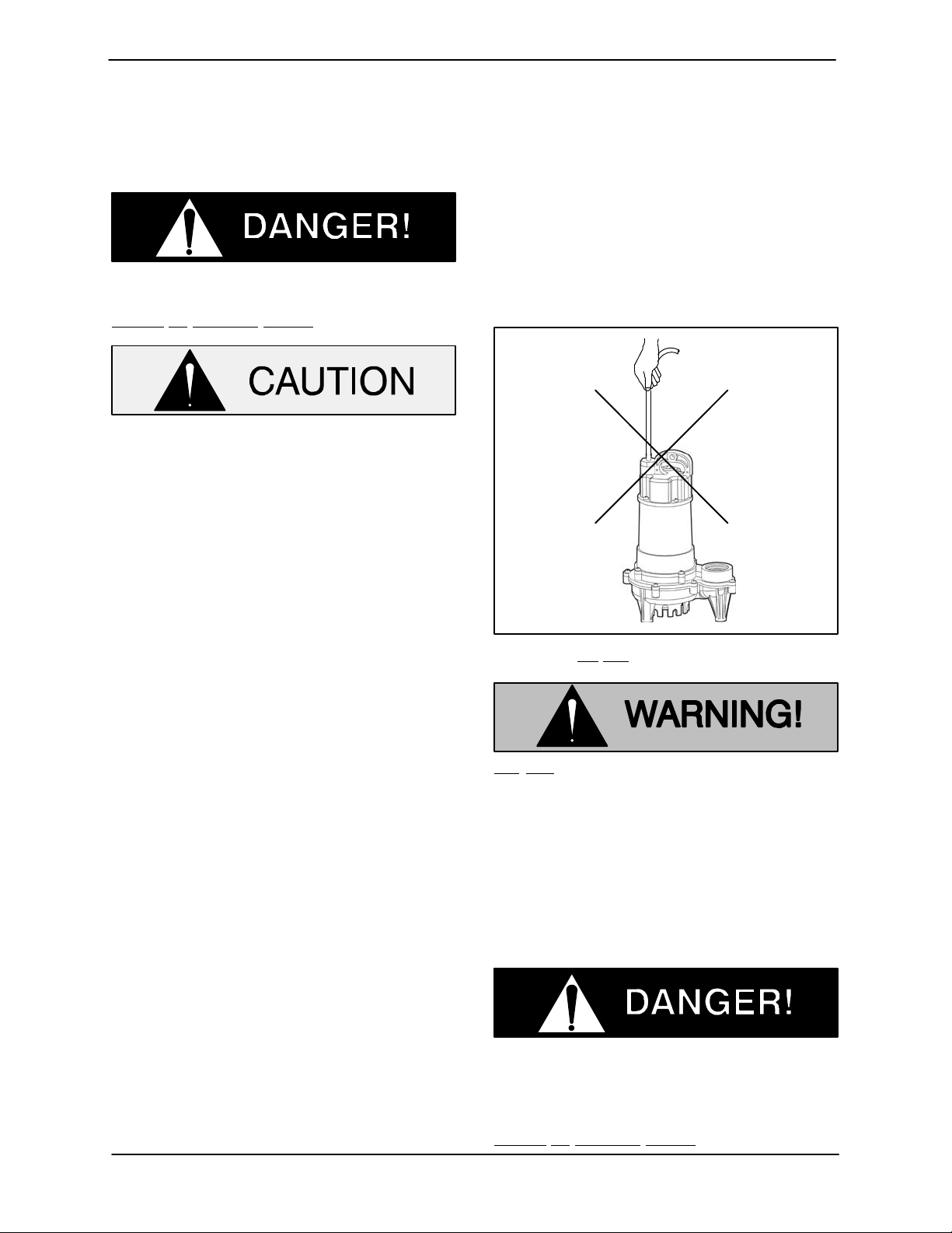
Figure 1. Do Not Lift Pump by Power Cable
Do not attempt to lift the pump by the
power cable or piping. Attach proper
lifting equipment to the handle on the
pump.
Installation
Before installing the pump, clear the sump basin of
any debris or sediment. See Figure 4 for a typical
pump installation.
The sump basin must be vented in ac
cordance with local plumbing codes.
Do not operate this pump where explo
sive vapors or flammable material exist.
Death or serious injury will result.
3INSTALLATION
Page 6

OM-06617 SE SERIES
The pump must be installed in a suitable gas‐tight,
properly vented basin which is at least 24 inches
(610 mm) deep and is at least 18 inches (457 mm)
wide for pumps fitted with wide angle (ball type) on/
off switches, and at least 14 inches (356 mm) wide
for pumps fitted with vertical on/off switches.
The pump must be placed on a hard surface in a
sump that has been cleared of all debris. Never
place the pump on clay, earth or gravel surfaces. It
is suggested that the pump be positioned on two
bricks approximately 2 inches (51 mm) apart.
Connect the discharge pipe, fittings and check
valve (if desired) to the discharge port of the pump.
It is recommended that the discharge pipe diamet
er be equal to or larger than the discharge size of
the pump.
The pump will handle 3/8 inch (9,5 mm) diameter
spherical solids.
Piping
precedence. All electrical equipment sup
plied with this pump was in conformance
with N.E.C. requirements in effect on the
date of manufacture. Failure to follow appli
cable specifications, or substitution of elec
trical parts not supplied or approved by the
manufacturer, can result in severe injury or
death and void warranty.
Always use a three‐prong grounded re
ceptacle. It is strongly recommended
that a Ground Fault Interrupter (GFI)
type receptacle (or equivalent) be used.
Either hose or rigid PVC, galvanized steel or cop
per pipe may be used for the discharge connec
tion.
For maximum pumping capacity, use non‐collaps
ible hose or rigid piping, and keep the discharge as
short and straight as possible. If rigid piping is
used, minimize the use of elbows and fittings which
increase friction losses and reduce pump perform
ance.
All piping must be clean and free of all foreign mat
ter to prevent clogging.
A check valve or throttling valve may be installed in
the discharge line to control siphoning or back flow
when the pump is shut off.
ELECTRICAL CONNECTIONS
All electrical connections must be in accor
dance with The National Electric Code and
all local codes. If there is a conflict between
the instructions provided and N.E.C. Speci
fications, N.E.C. Specifications shall take
Figure 2. Always Use a Grounded Receptacle
Verify that the voltage and frequency
shown on the pump name plate corres
ponds to those available at the recept
acle. The installer must make certain
that the electrical system is grounded in
accordance with code.
The receptacle into which the pump is to be
plugged must be connected to a separate 15 amp
circuit breaker or fuse block. Plugging into existing
outlets may cause low voltage at the motor, which
could cause tripped circuit breakers or blown
fuses in the service panel, tripping of the motor
overload or a burned out motor. When in doubt, call
an electrician.
A permanent ground connection from the recept
acle to the grounding bar at the service panel is
mandatory. These pumps are equipped with a
grounding conductor and a grounding‐type plug.
4 INSTALLATION
Page 7

OM-06617SE SERIES
Never cut off the ground pin or use an adaptor fit
ting. Do not use an extension cord. For maximum
safety, connect the pump to a circuit equipped with
a ground fault interrupter (GFI) type receptacle.
The plug and receptacle should be protected from
moisture and flooding. Protect the plug and power
cable from heat and sharp edges.
Figure 3. Always Keep Plug End Dry
PRECAUTIONS
The following may cause severe damage to the
pump and will void the pump warranty.
1. Using an extension cord.
2. Cutting off the ground pin or using an adaptor
fitting.
3. Working on the pump or switch while the
pump is plugged into the receptacle.
4. Removing the motor housing, unscrewing the
impeller, or removing the pump seal.
5. Running the pump continuously.
6. Pumping chemicals or corrosive liquids.
7. Pumping petroleum products or other flam
mable liquids.
Figure 4. Typical Sump Pump Installation
5INSTALLATION
Page 8

OM-06617
SE SERIES
OPERATION
Review all SAFETY information in Section A.
Follow the instructions on all tags, labels and
decals attached to the pump.
PUMP OPERATION
Do not operate this pump where explo
sive vapors or flammable material exist.
Death or serious injury will result.
This pump is designed to handle dirty
water that does not contain large en
trained solids. It is not designed to
pump volatile, flammable or corrosive
materials. Do not attempt to pump any
liquids which may damage the pump or
endanger personnel as a result of pump
failure.
Always keep the plug end dry.
Figure 1. Always Keep Plug End Dry
For manual operation, simply plug the power cable
into any 115 volt grounded receptacle. It is strong
ly recommended that a Ground Fault Interrupter
(GFI) type receptacle (or equivalent) be used (see
Figure 2).
Always use a three‐prong grounded re
ceptacle. It is strongly recommended
that a Ground Fault Interrupter (GFI)
type receptacle (or equivalent) be used.
Install the pump and piping as described in IN
STALLATION.
Operation of Pumps Without Integral Float
System
Each pump is provided with a 50‐foot (15 meter)
power cable. Never splice the power cable due to
safety and warranty considerations.
Never attempt to alter the length or re
pair any power cable with a splice. The
pump motor and cable must be com
pletely waterproof. Damage to the pump
or personal injury may result from alter
ations.
Figure 2. Always Use a Grounded Receptacle
Automatic Operation (Ball Type Float System)
Some units are equipped for automatic operation
with either a vertical slide or a ball type float system.
For automatic operation with a ball type float, al
ways make sure the float hangs free. It should not
come into contact with the bottom or side of the
sump.
OPERATION6
Page 9

SE SERIES
OM-06617
Plug the pump cable into a grounded receptacle.
It is strongly recommended that a Ground Fault In
terrupter (GFI) type receptacle (or equivalent) be
used (see Figure 2).
Operational Checks
Check the pump for proper operation when it is first
started and periodically thereafter to identify minor
problems.
Check the pump for unusual noises or excessive
vibration while it is operating. If noise or vibration is
excessive, stop the pump and refer to the
troubleshooting chart for possible causes.
Check the pump strainer screen for clogging
caused by stones, sticks, or other debris. Clean
the strainer screen when required. In some cases,
stopping the pump momentarily may back flush
the strainer screen, purging most of the debris
from it. If this fails to clean the screen, unplug the
pump, remove it from the sump, and remove the
debris manually.
Never introduce air or steam pressure into the
pump casing or piping to remove a blockage. This
could result in personal injury or damage to the
equipment.
STOPPING
To stop the pump when in manual mode, simply
unplug it from the receptacle. After stopping the
pump, be sure to perform all required maintenance
and preservation procedures.
This pump is equipped with automatic
thermal overload protection which will stop
the pump if overheating occurs. Unplug
the pump and allow it to cool before at
tempting to service the pump.
When operated in the automatic mode, the pump
will stop and start as the liquid level rises and falls.
For service or extended stopping, unplug the
pump from the receptacle.
Storage and Cold Weather Preservation
After stopping the pump, use the rope or chain at
tached to the lifting handle on the pump to remove
the pump from the sump. Do not lift the unit by the
power cable or the discharge piping. Customer in
stalled equipment such as rigid discharge piping
must be removed before attempting to lift.
Each of these pumps has a built‐in thermal protec
tion switch in the motor. The pump will stop if over
heating occurs. The pump will restart automatically
after it has cooled down.
Do not attempt to lift the pump by the
power cable or piping. Attach proper
lifting equipment to the handle on the
pump.
Clean the strainer screen before storage. If the
The integral thermal overload switch
will shut off the motor if the temperature
application involves a lot of mud or sludge, remove
the strainer and clean the impeller before storage.
rises above design limits. When the
pump cools and the temperature falls
below these limits, the motor will restart
automatically. To avoid the hazards of
The most common cause of failure to run is hard
ened mud or sludge in the impeller.
NOTE
an unexpected motor start‐up, unplug
the power cable from the receptacle be
fore attempting to handle the pump;
otherwise, serious personal injury
could result.
OPERATION 7
In freezing temperatures, the pump will not freeze
as long as it is submerged in liquid. If the pump
casing is not submerged, or if the liquid begins to
freeze, remove the pump from the sump and allow
Page 10

OM-06617
it to dry thoroughly. Run the pump for two or three
minutes to dry the inner walls.
If the pump freezes, move it into a warm area until
completely thawed, or submerge it into the liquid. If
the liquid is near freezing, the pump must be sub
merged for an extended period of time. Start the
pump and check for shaft rotation. If still frozen, al
low additional thawing time before attempting to
restart.
SE SERIES
Do not attempt to thaw the pump by using
a torch or other source of flame. This could
damage gaskets, electrical components,
or motor windings.
OPERATION8
Page 11

SE SERIES
TROUBLESHOOTING
Review all SAFETY information in Section A.
TROUBLE POSSIBLE CAUSE PROBABLE REMEDY
OM-06617
PUMP WILL NOT
RUN (MANUAL
MODE)
PUMP WILL NOT
RUN (AUTOMATIC
MODE)
MOTOR RUNS, BUT
PUMP FAILS TO
DELIVER WATER
Power cable loose in receptacle. Check.
GFI or circuit breaker tripped, fuse Check and reset GFI or breaker;
blown. replace fuse.
Hardened mud or sludge in pump. Check and clean.
Damaged power cable. Inspect and replace as required.
Liquid level device fouled with mud Clean liquid level device(s).
or foreign material.
Float type sensing device tangled or Check installation for free movement
obstructed. of float.
Strainer clogged. Check and clean as required.
Discharge line clogged or restricted; Check discharge lines; straighten
hose kinked. hose.
Liquid being pumped too thick. Dilute liquid by heating if possible.
Discharge check valve installed Check installation (arrow on valve
Backward. Should point in direction of flow).
Pumping entrained air. Check liquid level in sump; check
position of pump.
Pump is air locked. Start and stop pump several times by
plugging and unplugging cord.
Check for clogged vent hole in pump
casing.
Vertical pumping distance is too high. Reduce distance or change the
discharge fittings of the pump.
PUMP RUNS BUT
WILL NOT STOP
PUMP RUNS BUT
ONLY DELIVERS A
SMALL AMOUNT
OF WATER
TROUBLESHOOTING 9
Float stuck in up position. Check to ensure float operates
freely.
Pump is air locked. Start and stop pump several times by
plugging and unplugging cord.
Check for clogged vent hole in pump
casing.
Page 12

OM-06617
TROUBLESHOOTING (Cont'd)
Review all SAFETY information in Section A.
TROUBLE POSSIBLE CAUSE PROBABLE REMEDY
SE SERIES
PUMP RUNS BUT
ONLY DELIVERS A
SMALL AMOUNT
OF WATER
CIRCUIT BREAKER
TRIPS OR FUSE
BLOWS WHEN
PUMP STARTS
MOTOR RUNS, BUT
PUMP FAILS TO
DELIVER WATER
MOTOR RUNS FOR
A SHORT TIME,
THEN STOPS
Vertical pumping distance is too high. Reduce distance or change the
discharge fittings of the pump.
Strainer clogged. Check and clean as required.
Hardened mud or sludge in pump. Check and clean.
Damaged power cable. Inspect and replace as required.
Liquid level device fouled with mud Clean liquid level device(s).
or foreign material.
Float type sensing device tangled or Check installation for free movement
obstructed. of float.
Strainer or impeller clogged. Check and clean as required.
Circuit breaker or fuse too small. Check (must be 15 amps).
Strainer or impeller clogged. Check and clean as required.
TROUBLESHOOTING10
Page 13

Page 14

For U.S. and International Warranty Information,
Please Visit www.grpumps.com/warranty
or call:
U.S.: 419-755-1280
International: +1-419-755-1352
 Loading...