

Gorman-Rupp Pumps SE2D3A User Manual
OM-06495-01
August 11, 2011
Rev. A 12‐13‐12
INSTALLATION, OPERATION,
AND MAINTENANCE MANUAL
WITH PARTS LIST
SE SERIES PUMP
MODEL
SE2D3A 115V 1P
THE GORMAN‐RUPP COMPANY MANSFIELD, OHIO
GORMAN‐RUPP OF CANADA LIMITED ST. THOMAS, ONTARIO, CANADA Printed in U.S.A.
www.grpumps.com
2011 The Gorman‐Rupp Company

Register your new
Gorman‐Rupp pump online at
www.grpumps.com
Valid serial number and e‐mail address required.
RECORD YOUR PUMP MODEL AND SERIAL NUMBER
Please record your pump model and serial number in the
spaces provided below. Your Gorman‐Rupp distributor
needs this information when you require parts or service.
Pump Model:
Serial Number:

TABLE OF CONTENTS
INTRODUCTION PAGE I - 1.................................................
SAFETY ‐ SECTION A PAGE A - 1............................................
INSTALLATION - SECTION B PAGE B - 1....................................
GENERAL INFORMATION PAGE B - 1..................................................
PREINSTALLATION INSPECTION PAGE B - 1............................................
PUMP SEAL PAGE B - 1..............................................................
LUBRICATION PAGE B - 1.............................................................
PUMP INSTALLATION PAGE B - 2......................................................
Pump Motor Specifications PAGE B - 2..............................................
Pump Dimensions PAGE B - 2.....................................................
Lifting PAGE B - 2.................................................................
Positioning the Pump PAGE B - 2...................................................
Piping PAGE B - 3................................................................
ELECTRICAL CONNECTIONS PAGE B - 3...............................................
Grounding Methods PAGE B - 4....................................................
Pump Power Cable Connections PAGE B - 5.........................................
OPERATION - SECTION C PAGE C - 1......................................
GENERAL INFORMATION PAGE C - 1..................................................
Pump Performance PAGE C - 1.....................................................
Pump Controls PAGE C - 1........................................................
PUMP OPERATION PAGE C - 1........................................................
Liquid Temperature and Overheating PAGE C - 1.....................................
Impeller Rotation PAGE C - 2.......................................................
STARTING, STOPPING, AND OPERATIONAL CHECKS PAGE C - 3.........................
Starting And Stopping PAGE C - 3..................................................
Operational Checks PAGE C - 3....................................................
LIQUID LEVEL PAGE C - 4............................................................
COLD WEATHER PRESERVATION PAGE C - 4...........................................
LUBRICATION PAGE C - 4.............................................................
Draining Oil PAGE C - 4...........................................................
Condition Of Oil PAGE C - 4........................................................
Adding Oil PAGE C - 5............................................................
TROUBLESHOOTING - SECTION D PAGE D - 1..............................
ELECTRICAL TESTING PAGE D - 2.....................................................
Test Equipment PAGE D - 2........................................................
Voltage Imbalance PAGE D - 3.....................................................
Motor And Motor Power Cable Continuity PAGE D - 3.................................
Insulation Resistance PAGE D - 3...................................................
Capacitor PAGE D - 4.............................................................
Wiring Diagram PAGE D - 4........................................................
PUMP MAINTENANCE AND REPAIR ‐ SECTION E PAGE E - 1.................
STANDARD PERFORMANCE CURVE PAGE E - 1........................................
PUMP MODEL S2D3A 115V 1P PARTS LIST PAGE E - 3..................................
PUMP AND SEAL DISASSEMBLY AND REASSEMBLY PAGE E - 4.........................
i

TABLE OF CONTENTS
(continued)
PUMP END DISASSEMBLY PAGE E - 4.................................................
Strainer And Impeller Cover Removal PAGE E - 5.....................................
Draining Oil From Seal Cavity PAGE E - 5............................................
Positioning Pump For Disassembly PAGE E - 5.......................................
Impeller Removal PAGE E - 5......................................................
Seal Removal PAGE E - 5..........................................................
PUMP END REASSEMBLY PAGE E - 6..................................................
Cleaning And Inspection Of Pump Parts PAGE E - 6..................................
Seal Installation PAGE E - 6........................................................
Impeller Installation PAGE E - 8.....................................................
Impeller Clearance PAGE E - 8.....................................................
Strainer Installation PAGE E - 8....................................................
MOTOR DISASSEMBLY PAGE E - 9....................................................
Head And Power Cable Removal PAGE E - 9.........................................
Rotor And Shaft Removal PAGE E - 10...............................................
Bearing Removal PAGE E - 10.......................................................
Centrifugal Contact Switch Removal PAGE E - 10......................................
Stator Removal PAGE E - 10........................................................
MOTOR REASSEMBLY PAGE E - 11.....................................................
Stator Installation PAGE E - 11......................................................
Centrifugal Contact Switch Installation PAGE E - 12....................................
Bearing Installation PAGE E - 12.....................................................
Rotor And Shaft Installation PAGE E - 13.............................................
Head And Power Cable Installation PAGE E - 13.......................................
VACUUM/PRESSURE TESTING PAGE E - 14.............................................
LUBRICATION PAGE E - 15.............................................................
Seal Cavity PAGE E - 15............................................................
Motor Cavity PAGE E - 15...........................................................
ii
SE SERIES OM-06495
INTRODUCTION
Thank You for purchasing a Gorman‐Rupp pump.
Read this manual carefully to learn how to safely
install and operate your pump. Failure to do so
could result in personal injury or damage to the
pump.
This is an SE Series submersible pump. The basic
material of construction is cast iron, with stainless
steel hardware and fittings. The pump is light
weight and portable, making it ideally suited to
many domestic and industrial applications where
low capacity dewatering or irrigation is required.
The pump is powered by an integral, thermally‐
protected electric motor which is not explosion‐
proof. The pump may be operated fully or partially
submerged. Do not operate the pump in a hazard
ous atmosphere.
All repairs to the pump motor must be performed
by a Gorman‐Rupp authorized submersible repair
facility or the factory. Any repairs to the motor as
sembly performed by the customer or an unautho
rized repair facility negates the warranty.
Gorman‐Rupp of Canada Limited
70 Burwell Road
St. Thomas, Ontario N5P 3R7
Phone: (519) 631-2870
The following are used to alert maintenance per
sonnel to procedures which require special atten
tion, to those which could damage equipment, and
to those which could be dangerous to personnel:
Immediate hazards which WILL result in
severe personal injury or death. These
instructions describe the procedure re
quired and the injury which will result
from failure to follow the procedure.
Because pump installations are seldom identical,
this manual cannot possibly provide detailed in
structions and precautions for every aspect of
each specific application. Therefore, it is the re
sponsibility of the owner/installer of the pump to
ensure that applications not addressed in this
manual are performed only after establishing that
neither operator safety nor pump integrity are com
promised by the installation. Pumps and related
equipment must be installed and operated ac
cording to all national, local and industry stan
dards.
If there are any questions regarding the pump or
its application which are not covered in this man
ual or in other literature accompanying this unit,
please contact your Gorman‐Rupp distributor, or
The Gorman‐Rupp Company:
The Gorman‐Rupp Company
P.O. Box 1217
Mansfield, Ohio 44901-1217
Phone: (419) 755-1011
or:
Hazards or unsafe practices which
COULD result in severe personal injury
or death. These instructions describe
the procedure required and the injury
which could result from failure to follow
the procedure.
Hazards or unsafe practices which COULD
result in minor personal injury or product
or property damage. These instructions
describe the requirements and the possi
ble damage which could result from failure
to follow the procedure.
NOTE
Instructions to aid in installation, operation, and
maintenance or which clarify a procedure.
PAGE I - 1INTRODUCTION
SE SERIES OM-06495
SAFETY - SECTION A
This information applies to SE Series
submersible motor driven pumps.
Because pump installations are seldom
identical, this manual cannot possibly
provide detailed instructions and pre
cautions for each specific application.
Therefore, it is the owner/installer's re
sponsibility to ensure that applications
not addressed in this manual are per
formed only after establishing that nei
ther operator safety nor pump integrity
are compromised by the installation.
Before attempting to open or service the
pump:
1. Familiarize yourself with this man
ual.
2. Unplug the power cable from its re
ceptacle to ensure that the pump
will remain inoperative.
3. Allow the pump to completely cool
if overheated.
5. Close the discharge valve (if
used).
This pump is not designed to pump vol
atile, explosive, or flammable materials.
Do not attempt to pump any liquids for
which you pump is not approved, or
which may damage the pump or endan
ger personnel as a result of pump fail
ure. Consult the factory for specific ap
plication data.
The electrical power used to operate
this pump is high enough to cause inju
ry or death. Make certain that the power
cable receptacle is properly grounded
before installation.
The electrical power used to operate
this pump is high enough to cause inju
ry or death. Make certain that the plug
on the pump power cable is discon
nected from its receptacle before ser
vicing.
The electrical power used to operate
this pump is high enough to cause inju
ry or death. Obtain the services of a
qualified electrician to make all electri
cal connections.
Never attempt to alter the length or re
pair any power cable with a splice. The
pump motor and cable must be com
pletely waterproof. Injury or death may
result from alterations.
All electrical connections must be in ac
cordance with The National Electric
Code and all local codes. If there is a
conflict between the instructions pro
vided and N.E.C. Specifications, N.E.C.
Specifications shall take precedence.
All electrical equipment supplied with
this pump was in conformance with
N.E.C. requirements in effect on the
SAFETY
PAGE A - 1
OM-06495 SE SERIES
date of manufacture. Failure to follow
applicable specifications, or substitu
tion of electrical parts not supplied or
approved by the manufacturer, can re
sult in severe injury or death and void
warranty.
After the pump has been installed, make
certain that the pump and all piping or
hose connections are secure before op
eration.
Obtain the services of a qualified elec
trician to troubleshoot, test and/or ser
vice the electrical components of this
pump.
Do not attempt to lift the pump by the
motor power cable or discharge hose.
Attach proper lifting equipment to the
lifting device fitted to the pump.
Pumps and related equipment must be
installed and operated according to all na
tional, local and industry standards.
PAGE A - 2 SAFETY
OM-06493 SE SERIES
INSTALLATION - SECTION B
GENERAL INFORMATION
Review all SAFETY information in Section A.
Since pump installations are seldom identical, this
section is intended only to summarize general rec
ommendations and practices required to inspect,
position, and arrange the pump and piping. If there
are any questions concerning your specific instal
lation, contact your Gorman‐Rupp distributor or
the Gorman‐Rupp Company.
Nuts, bolts and screws used on this pump
are metric and do not match standard SAE
measurement threads. If any threaded
hardware is replaced, it must be replaced
with metric type. Attempting to force in a
fastener with SAE threads will damage the
mating threads. An optional discharge
adaptor is available to convert the metric
pipe threads in the discharge flange to the
SAE threads.
PREINSTALLATION INSPECTION
The pump assembly was inspected and tested be
fore shipment from the factory. Before installation,
check for damage which may have occurred dur
ing shipment. Check as follows:
a. Inspect the pump assembly for cracks, dents,
damaged threads, and other obvious dam
age.
e. Carefully read all tags, decals, and markings
on the pump, and perform all duties indicated.
f. Check for oil leaks. If there is any indication of
an oil leak, see LUBRICATION at the end of
this manual.
g. If the pump has been stored for more than 12
months, some of the components or lubri
cants may have exceeded their maximum
shelf life. These must be inspected or re
placed to ensure maximum pump service.
If the maximum shelf life has been exceed, or if
anything appears to be abnormal, contact
your Gorman‐Rupp distributor or the factory
to determine the repair or updating policy. Do
not put the pump into service until appropri
ate action has been taken.
PUMP SEAL
The pump is equipped with a single faced seal as
sembly. It is designed to prevent the liquid being
pumped from entering the lubrication cavity at the
impeller end. A lip seal is used to prevent moisture
or lubrication oil from entering the motor housing
cavity at the motor end.
The seal is lubricated by premium quality submers
ible pump oil.
LUBRICATION
The pump utilizes one lubrication cavity, located
between the pump casing and the motor housing.
It is filled with premium quality submersible pump
oil which lubricates the pump seal. The motor oper
ates in and is cooled by air, therefore it requires no
lubrication.
b. Check for and tighten loose attaching hard
ware. Since gaskets tend to shrink after dry
ing, check for and tighten loose hardware at
the mating surfaces.
c. Inspect the power cable for cuts or any other
obvious damage.
d. Check that amperes, phase, voltage and
hertz indicated on the name plate match the
ratings on the control box and incoming pow
er.
This pump was fully lubricated when shipped from
the factory. However, lubrication levels must be
checked before installing the pump (see LU
BRICATION in the MAINTENANCE AND REPAIR
MANUAL). If the oil level is abnormally low, deter
mine the cause before putting the pump into ser
vice.
Refer to Table B‐2 for the oil capacity and position
for filling the seal cavity in the pump. Refer to LU
BRICATION, Section C for lubrication specifica
tions and intervals.
PAGE B - 1INSTALLATION
SE SERIES
PUMP INSTALLATION
Pump Motor Specifications
See Tables B‐1 and B‐2 for pump specifications.
Table B‐1. Pump Specifications
OM-06493
Model Voltage/
Phase
SE2D3A 115/1 YES 8.6 1.0 50.61 HP 3450
Pump
Model
Voltage/
Phase
115/1SE2D3A
Liquid
Level
Control
Pump
78 (42) 6 (3) 7 (0,2) HORIZONTAL
Pump
HP/
KW
Table B‐2. Additional Specifications
Approximate
Weight - Lbs. (kg)
Motor
Speed
(RPM)
50 Ft. Cable
When installing or servicing the pump
or controls, follow all requirements for
the installation of wiring or electrical
equipment as outlined in the National
Electric Code. Follow all safety require
ments. Failure to observe these require
ments could result in injury or death to
personnel.
Full
Load
Amperes
Ounces (Liters)
Seal
Cavity
Lifting
Pump unit weights will vary depending on the
mounting and drive provided. Check the shipping
tag on the unit packaging for the actual weight, and
use lifting equipment with appropriate capacity.
Drain the pump and remove all customer‐installed
equipment such as suction and discharge hoses
or piping before attempting to lift existing, installed
units.
No
Load
Amperes
Oil Capacity
Locked
Amperes
Motor
Cavity
---
Rotor
Discharge
Size
(NPT)
2 INCH
w/BARBED
ADAPTOR
Seal Cavity
Filling
Position
(H)orizontal
NOTE
Refer to the performance curve in Section E, Main
tenance and Repair when determining the most
efficient piping installation. The recommended
maximum submergence depth is 23 feet. Great
er depths could result in damage to the pump
Pump Dimensions
For the approximate physical dimensions of your
pump, refer to the pump specification data sheet
or contact your Gorman‐Rupp distributor or the
Gorman‐Rupp Company.
PAGE B - 2 INSTALLATION
Do not attempt to lift the pump by the
motor power cable or the piping. Attach
proper lifting equipment or a rope to the
lifting device fitted to the pump.
Positioning the Pump
The pump is designed to operate fully or partially
submerged. The rotating parts are oil lubricated,
and the motor is cooled by a constant flow of liquid
or air discharged through internal passages.
The pump will operate if positioned on its side, but
this is not recommended because the motor
OM-06493 SE SERIES
torque could cause the pump to roll during opera
tion.
The pump should be independently secured and
supported by the lifting device fitted on the pump.
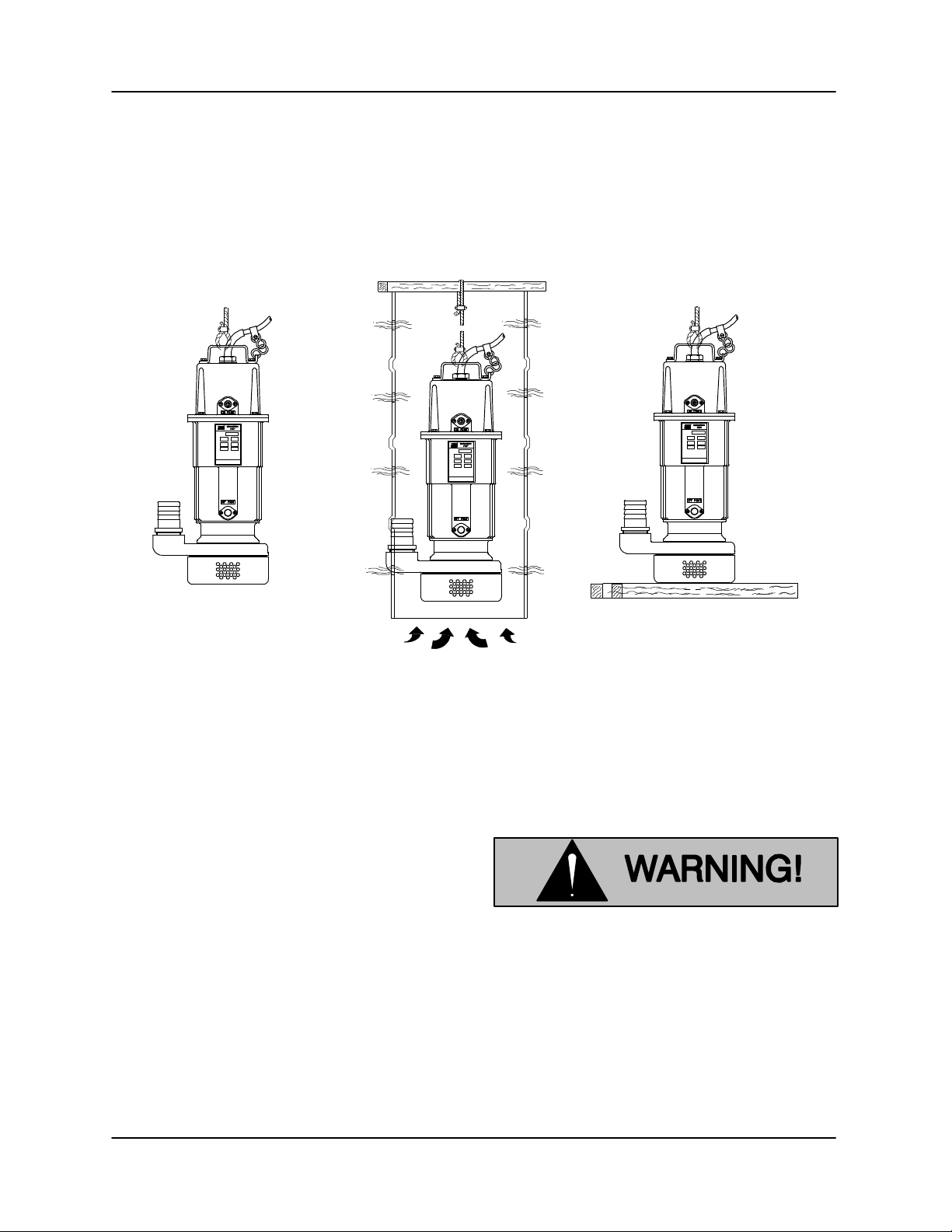
If the application involves a lot of debris, protect the
pump from excessive wear and clogging by sus
pending it in a perforated barrel or culvert pipe. If
the bottom is heavily sludge‐covered, rest the
pump on support blocks or suspend it from a raft
or similar device near the surface of the liquid. See
Figure B‐1 for typical pump installations.
All liquid entering the pump must pass through a
strainer screen. Any spherical solids which pass
through the screen will pass through the pump.
BY BAIL IN PERFORATED CULVERT PIPE ON SUPPORTS
Figure B‐1. Typical Pump Installations
Piping
No suction piping is required in a standard installa
tion. This pump is provided with a suction strainer
to prevent large solids from clogging the impeller.
To determine the size of the discharge connection,
see Table B‐1. Either hose or rigid pipe may be
used. To facilitate mobility and maintenance, it is
recommended that the discharge line be fitted with
a quick disconnect fitting near the pump. The dis
charge line must be independently supported to
avoid strain and vibration on the pump.
Either hose or rigid pipe may be used to make dis
charge connections. For maximum pumping ca
pacity, keep the line as short and straight as pos
sible. Elbows and fittings used in discharge lines
increase friction loss, minimize their use.
It is recommended that a check valve or throttling
valve be installed in the discharge line to control si
phoning or back flow when the pump is shut off.
ELECTRICAL CONNECTIONS
Install and operate this pump in accor
dance with the National Electrical Code
and all local codes. Have a qualified
electrician perform all checks and con
nections in this section.
Never attempt to alter the length of the
pump motor cable or to repair it with a
splice. The power cable and pump mo
tor must be kept completely waterproof.
PAGE B - 3INSTALLATION
SE SERIES
OM-06493
Serious damage to the pump and injury
or death to personnel can result from
any alteration to the cable.
Field Wiring Connections (Incoming Power)
The pump is designed to operate with a 115 volt,
1 phase, 60 hertz power supply. The voltage avail
able at the motor must be within the range indi
cated in Table B‐3.
To calculate the voltage available at the motor, pro
ceed as follows:
a. Measure the voltage while the pump is oper
ating at full capacity. See wiring diagrams at
the end of this section.
b. Next, subtract the motor cable voltage drop
(see Table B‐4, Pump Power Cable Specifi
cations).
c. Do not continue to operate the pump if this
voltage is not within the recommended limits.
Obtain the services of a qualified electrician to
determine the correct field wiring size and oth
er details to ensure an adequate voltage sup
ply to the pump.
Pump Power Cable Connections
The electrical power used to operate
this pump is high enough to cause inju
ry or death. Obtain the services of a
qualified electrician to make all electri
cal connections. Make certain that the
pump and receptacle are properly
grounded.
The pump is provided with a 50 ft. (15,2 m) power
cable (see Table B‐4 for standard power cable
specifications) with one end wired into the pump
head. The other end terminates in a grounded
power plug. Power to the receptacle must be di
rected through a fused circuit, and the receptacle
must be controlled by a positive ON/OFF switch.
The use of extension cords is not recommended.
If extension cords are used, they must have three‐
wire single phase construction and have adequate
carrying capacity for their length.
Table B‐3. Pump Voltage Requirements
NOMINAL
VOLTAGE
Pump
Model
When necessary to service the pump, make cer
tain the power cable is unplugged from the recep
tacle.
PHASE
1115 110 120
Voltage/
Phase
115/1
MINIMUM
VOLTAGE
Table B‐4. Pump Power Cable Specifications
A.W.G
Cable
Size
16 13* SO 7.72SE2D3A 0.43 (11) 0.06 (1,5) 4.49
MAXIMUM
VOLTAGE
Cable
O.D.
Inches
(mm)
Conductor
Inches
(mm)
Dia.
Never attempt to alter the length or re
pair any power cable with a splice. The
pump motor and cable must be com
pletely waterproof. Injury or death may
result from alternations.
DC
Amp
Rating
(See
Note
Below)
Cable
Type
Resistance
(ohms) at
225_C (77_F)
per 1000 ft.
(305 m)
Voltage
Drop
per 100 ft.
(30,5m) at
Max. Load
PAGE B - 4 INSTALLATION
OM-06493 SE SERIES
Motor Cable Grounding Test
The electrical power used to operate
this pump is high enough to cause inju
ry or death. Make certain that the power
cable receptacle is properly grounded
after installation.
Using a volt‐ohm meter, connect one lead to the
motor cable green/yellow ground lead. Connect
the other lead to an uninsulated point on the pump
body. The test circuit should close.
If the test circuit does not close, there is a defect in
the cable or motor which must be corrected.
Liquid Level Devices
The pump is furnished with built‐in devices to auto
matically regulate liquid level by filling and dewa
tering. When liquid level reaches the on‐point (up
per) device, the pump will switch on and continue
to run until liquid level falls below the off‐point (low
er) device.
NOTE
Distilled water or uncontaminated rain water may
fail to provide conductivity necessary to trigger the
automatic liquid level sensing devices built into the
pump. If this occurs, ground the on‐point assembly
to convert the pump to manual operation, and
install a float level control system.
Overheating will occur if the liquid level falls
below the level required to cool the pump
motor (see LIQUID LEVEL in Operation,
Section C).
PAGE B - 5INSTALLATION
 Loading...