

Page 1
OM−06490−01
August 10, 2011
INSTALLATION, OPERATION,
AND MAINTENANCE MANUAL
WITH PARTS LIST
T
HANDY-SUB
SUBMERSIBLE PUMP
MODEL
SE1 1/2B3−E.33 12V
THE GORMAN-RUPP COMPANY F MANSFIELD, OHIO
GORMAN-RUPP OF CANADA LIMITED D ST. THOMAS, ONTARIO, CANADA Printed in U.S.A.
E2011 The Gorman-Rupp Company
Page 2

Register your new
Gorman-Rupp pump online at
www.grpumps.com
Valid serial number and e-mail address required.
RECORD YOUR PUMP MODEL AND SERIAL NUMBER
Please record your pump model and serial number in the
spaces provided below. Your Gorman-Rupp distributor
needs this information when you require parts or service.
Pump Model:
Serial Number:
Page 3

TABLE OF CONTENTS
INTRODUCTION PAGE I − 1. . . . . . . . . . . . . . . . . . . . . . . . . . . . . . . . . . . . . . . . . . . . . . . . .
SAFETY - SECTION A PAGE A − 1. . . . . . . . . . . . . . . . . . . . . . . . . . . . . . . . . . . . . . . . . . . .
INSTALLATION − SECTION B PAGE B − 1. . . . . . . . . . . . . . . . . . . . . . . . . . . . . . . . . . . .
PREINSTALLATION INSPECTION PAGE B − 1. . . . . . . . . . . . . . . . . . . . . . . . . . . . . . . . . . . . . . . . . . . .
Lubrication PAGE B − 1. . . . . . . . . . . . . . . . . . . . . . . . . . . . . . . . . . . . . . . . . . . . . . . . . . . . . . . . . . . .
PUMP INSTALLATION PAGE B − 1. . . . . . . . . . . . . . . . . . . . . . . . . . . . . . . . . . . . . . . . . . . . . . . . . . . . . .
Pump Dimensions PAGE B − 1. . . . . . . . . . . . . . . . . . . . . . . . . . . . . . . . . . . . . . . . . . . . . . . . . . . . .
Lifting PAGE B − 2. . . . . . . . . . . . . . . . . . . . . . . . . . . . . . . . . . . . . . . . . . . . . . . . . . . . . . . . . . . . . . . . .
Positioning the Pump PAGE B − 2. . . . . . . . . . . . . . . . . . . . . . . . . . . . . . . . . . . . . . . . . . . . . . . . . . .
Typical Pump Installations PAGE B − 2. . . . . . . . . . . . . . . . . . . . . . . . . . . . . . . . . . . . . . . . . . . . . . .
PIPING PAGE B − 3. . . . . . . . . . . . . . . . . . . . . . . . . . . . . . . . . . . . . . . . . . . . . . . . . . . . . . . . . . . . . . . . . . .
PUMP POWER CABLE CONNECTIONS PAGE B − 3. . . . . . . . . . . . . . . . . . . . . . . . . . . . . . . . . . . . . .
OPERATION − SECTION C PAGE C − 1. . . . . . . . . . . . . . . . . . . . . . . . . . . . . . . . . . . . . .
PUMP OPERATION PAGE C − 1. . . . . . . . . . . . . . . . . . . . . . . . . . . . . . . . . . . . . . . . . . . . . . . . . . . . . . . .
Switching PAGE C − 1. . . . . . . . . . . . . . . . . . . . . . . . . . . . . . . . . . . . . . . . . . . . . . . . . . . . . . . . . . . . .
Running Time PAGE C − 1. . . . . . . . . . . . . . . . . . . . . . . . . . . . . . . . . . . . . . . . . . . . . . . . . . . . . . . . .
Overload Protection PAGE C − 1. . . . . . . . . . . . . . . . . . . . . . . . . . . . . . . . . . . . . . . . . . . . . . . . . . . .
Operational Checks PAGE C − 1. . . . . . . . . . . . . . . . . . . . . . . . . . . . . . . . . . . . . . . . . . . . . . . . . . . .
STOPPING PAGE C − 2. . . . . . . . . . . . . . . . . . . . . . . . . . . . . . . . . . . . . . . . . . . . . . . . . . . . . . . . . . . . . . . .
Storage and Cold Weather Preservation PAGE C − 2. . . . . . . . . . . . . . . . . . . . . . . . . . . . . . . . . .
TROUBLESHOOTING − SECTION D PAGE D − 1. . . . . . . . . . . . . . . . . . . . . . . . . . . . . .
ELECTRICAL TESTING PAGE D − 2. . . . . . . . . . . . . . . . . . . . . . . . . . . . . . . . . . . . . . . . . . . . . . . . . . . . .
Test Equipment PAGE D − 2. . . . . . . . . . . . . . . . . . . . . . . . . . . . . . . . . . . . . . . . . . . . . . . . . . . . . . . .
Power Cable Continuity Check PAGE D − 2. . . . . . . . . . . . . . . . . . . . . . . . . . . . . . . . . . . . . . . . . . .
Circuit Breaker Check PAGE D − 2. . . . . . . . . . . . . . . . . . . . . . . . . . . . . . . . . . . . . . . . . . . . . . . . . .
On-Off Switch Check PAGE D − 2. . . . . . . . . . . . . . . . . . . . . . . . . . . . . . . . . . . . . . . . . . . . . . . . . . .
PUMP MAINTENANCE AND REPAIR - SECTION E PAGE E − 1. . . . . . . . . . . . . . . . .
PERFORMANCE CURVE PAGE E − 1. . . . . . . . . . . . . . . . . . . . . . . . . . . . . . . . . . . . . . . . . . . . . . . . . . .
PARTS LIST:
Pump Model PAGE E − 3. . . . . . . . . . . . . . . . . . . . . . . . . . . . . . . . . . . . . . . . . . . . . . . . . . . . . . . . . .
PUMP AND SEAL DISASSEMBLY AND REASSEMBLY PAGE E − 4. . . . . . . . . . . . . . . . . . . . . . . . .
PUMP END DISASSEMBLY PAGE E − 4. . . . . . . . . . . . . . . . . . . . . . . . . . . . . . . . . . . . . . . . . . . . . . . . .
Strainer Removal PAGE E − 4. . . . . . . . . . . . . . . . . . . . . . . . . . . . . . . . . . . . . . . . . . . . . . . . . . . . . . .
Impeller Removal PAGE E − 5. . . . . . . . . . . . . . . . . . . . . . . . . . . . . . . . . . . . . . . . . . . . . . . . . . . . . .
Seal Removal PAGE E − 5. . . . . . . . . . . . . . . . . . . . . . . . . . . . . . . . . . . . . . . . . . . . . . . . . . . . . . . . . .
PUMP END REASSEMBLY PAGE E − 5. . . . . . . . . . . . . . . . . . . . . . . . . . . . . . . . . . . . . . . . . . . . . . . . . .
Cleaning And Inspection Of Pump Parts PAGE E − 5. . . . . . . . . . . . . . . . . . . . . . . . . . . . . . . . . .
Seal Installation PAGE E − 6. . . . . . . . . . . . . . . . . . . . . . . . . . . . . . . . . . . . . . . . . . . . . . . . . . . . . . . .
Impeller Installation PAGE E − 7. . . . . . . . . . . . . . . . . . . . . . . . . . . . . . . . . . . . . . . . . . . . . . . . . . . . .
Strainer Installation PAGE E − 7. . . . . . . . . . . . . . . . . . . . . . . . . . . . . . . . . . . . . . . . . . . . . . . . . . . . .
MOTOR DISASSEMBLY PAGE E − 7. . . . . . . . . . . . . . . . . . . . . . . . . . . . . . . . . . . . . . . . . . . . . . . . . . . .
i
Page 4

TABLE OF CONTENTS
(continued)
Cable Assembly and Motor Cover Removal PAGE E − 7. . . . . . . . . . . . . . . . . . . . . . . . . . . . . . .
Motor Circuit Breaker Removal PAGE E − 8. . . . . . . . . . . . . . . . . . . . . . . . . . . . . . . . . . . . . . . . . .
Motor Brush Removal PAGE E − 8. . . . . . . . . . . . . . . . . . . . . . . . . . . . . . . . . . . . . . . . . . . . . . . . . .
MOTOR REASSEMBLY PAGE E − 8. . . . . . . . . . . . . . . . . . . . . . . . . . . . . . . . . . . . . . . . . . . . . . . . . . . . .
Motor Brush Installation PAGE E − 8. . . . . . . . . . . . . . . . . . . . . . . . . . . . . . . . . . . . . . . . . . . . . . . . .
Motor Circuit Breaker Installation PAGE E − 8. . . . . . . . . . . . . . . . . . . . . . . . . . . . . . . . . . . . . . . . .
Cable Assembly and Motor Cover Installation PAGE E − 8. . . . . . . . . . . . . . . . . . . . . . . . . . . . . .
ii
Page 5
SE SERIES
OM−06490
INTRODUCTION
Thank You for purchasing a Gorman-Rupp pump.
Read this manual carefully to learn how to safely
install and operate your pump. Failure to do so
could result in personal injury or damage to the
pump.
This pump is an SE Series, Handy-SubT submersible model, designed to handle dirty water that
does not contain large entrained solids. Do not attempt to pump volatile, flammable or corrosive liquids that may damage the pump. The basic material of construction is aluminum, with a cast iron impeller.
The pump may be operated fully or partially submerged, but should not be operated dry for extended periods. The integral 1/3 H.P. electric motor
may be driven by any standard 12-volt DC vehicle
battery. The pump is not explosion-proof, and
should not be operated in a hazardous atmosphere.
This manual will alert personnel to known procedures which require special attention, to those
which could damage equipment, and to those
which could be dangerous to personnel. However,
this manual cannot possibly anticipate and provide
detailed precautions for every situation that might
occur during maintenance of the unit. Therefore, it
is the responsibility of the owner/maintenance personnel to ensure that only safe, established main-
tenance procedures are used, and that any procedures not addressed in this manual are performed
only after establishing that neither personal safety
nor pump integrity are compromised by such practices.
If there are any questions regarding the pump or
its application which are not covered in this manual or in other literature accompanying this unit,
please contact your Gorman-Rupp distributor, or
the Gorman-Rupp Company:
The Gorman-Rupp Company
P.O. Box 1217
Mansfield, Ohio 44901−1217
Phone: (419) 755−1011
or:
Gorman-Rupp of Canada Limited
70 Burwell Road
St. Thomas, Ontario N5P 3R7
Phone: (519) 631−2870
The following are used to alert maintenance personnel to procedures which require special attention, to those which could damage equipment, and
to those which could be dangerous to personnel:
Immediate hazards which WILL result in
severe personal injury or death. These
instructions describe the procedure required and the injury which will result
from failure to follow the procedure.
Hazards or unsafe practices which
COULD result in severe personal injury
or death. These instructions describe
the procedure required and the injury
which could result from failure to follow
the procedure.
Hazards or unsafe practices which COULD
result in minor personal injury or product
or property damage. These instructions
describe the requirements and the possible damage which could result from failure
to follow the procedure.
NOTE
Instructions to aid in installation, operation, and
maintenance or which clarify a procedure.
PAGE I − 1INTRODUCTION
Page 6
SE SERIES
OM−06490
SAFETY - SECTION A
This information applies to the SE Series Handy-SubT submersible electric
motor driven pump.
Do not operate this pump where explosive vapors or flammable material exist.
Death or serious injury will result.
Check the National Electric Code
(N.E.C.) and local codes before using.
Before attempting to open or service the
pump:
1. Familiarize yourself with this manual.
2. Switch off the pump and disconnect the power cables from the vehicle battery to ensure that the
pump will remain inoperative.
3. Allow the pump to cool if overheated.
This pump is designed to handle dirty
water that does not contain large entrained solids. It is not designed to
pump volatile, flammable or corrosive
materials. Do not attempt to pump any
liquids which may damage the pump or
endanger personnel as a result of pump
failure.
casing, electrical shock could occur,
causing severe injury or death to personnel.
Always make sure the switch on the
power cables is in the OFF position before connecting the leads to the vehicle
battery. Failure to do so could cause
arcing, resulting in explosion or fire.
Never attempt to alter the length or repair any power cable with a splice. The
pump motor and cable must be completely waterproof. Damage to the pump
or personal injury may result from alterations.
After the pump has been installed, make
certain that the pump and all piping or
hose connections are secure before operation.
Do not attempt to lift the pump by the
power cables, carry handle or piping.
Attach proper lifting equipment to the
lifting eye fitted to the pump.
Do not allow the pump and vehicle to
come into contact when connecting the
power cable to the battery. If the pump
should develop an internal short to the
Obtain the services of a qualified electrician to troubleshoot, test and/or service the electrical components of this
pump.
PAGE A − 1SAFETY
Page 7

INSTALLATION − SECTION B
OM−06490SE SERIES
Review all SAFETY information in Section A.
Do not operate this pump where explosive vapors or flammable material exist.
Death or serious injury will result.
Check the National Electric Code
(N.E.C.) and local codes before using.
This section only summarizes recommended installation practices for the pump. If there are questions concerning your specific application, contact
your local distributor or the Gorman-Rupp Company.
PREINSTALLATION INSPECTION
The pump was inspected and tested before shipment from the factory. Before installation, inspect
the pump for damage which may have occurred
during shipment. Check as follows:
a. Inspect the pump assembly for cracks, dents,
damaged threads, and other obvious damage.
c. The standard pump is furnished with two
30-foot (3 m) long power cables. Inspect the
cables for cuts or damage.
d. Screw the lifting eye (shipped loose) into the
tapped hole in the top of the motor cover until
fully seated, and secure it with the jam nut.
e. Carefully read all tags, decals, and markings
on the pump assembly, and perform all duties
as indicated.
If anything appears to be abnormal, contact your
Gorman-Rupp distributor or the factory to determine the repair or updating policy. Do not put the
pump into service until appropriate action has
been taken.
Lubrication
The shaft seal in this pump is lubricated by the medium being pumped. The bearings in this pump
are permanently lubricated for life. No additional lubrication is required.
PUMP INSTALLATION
Pump Dimensions
b. Check for and tighten loose attaching hard-
ware. Since gaskets tend to shrink after drying, check for loose hardware at mating surfaces.
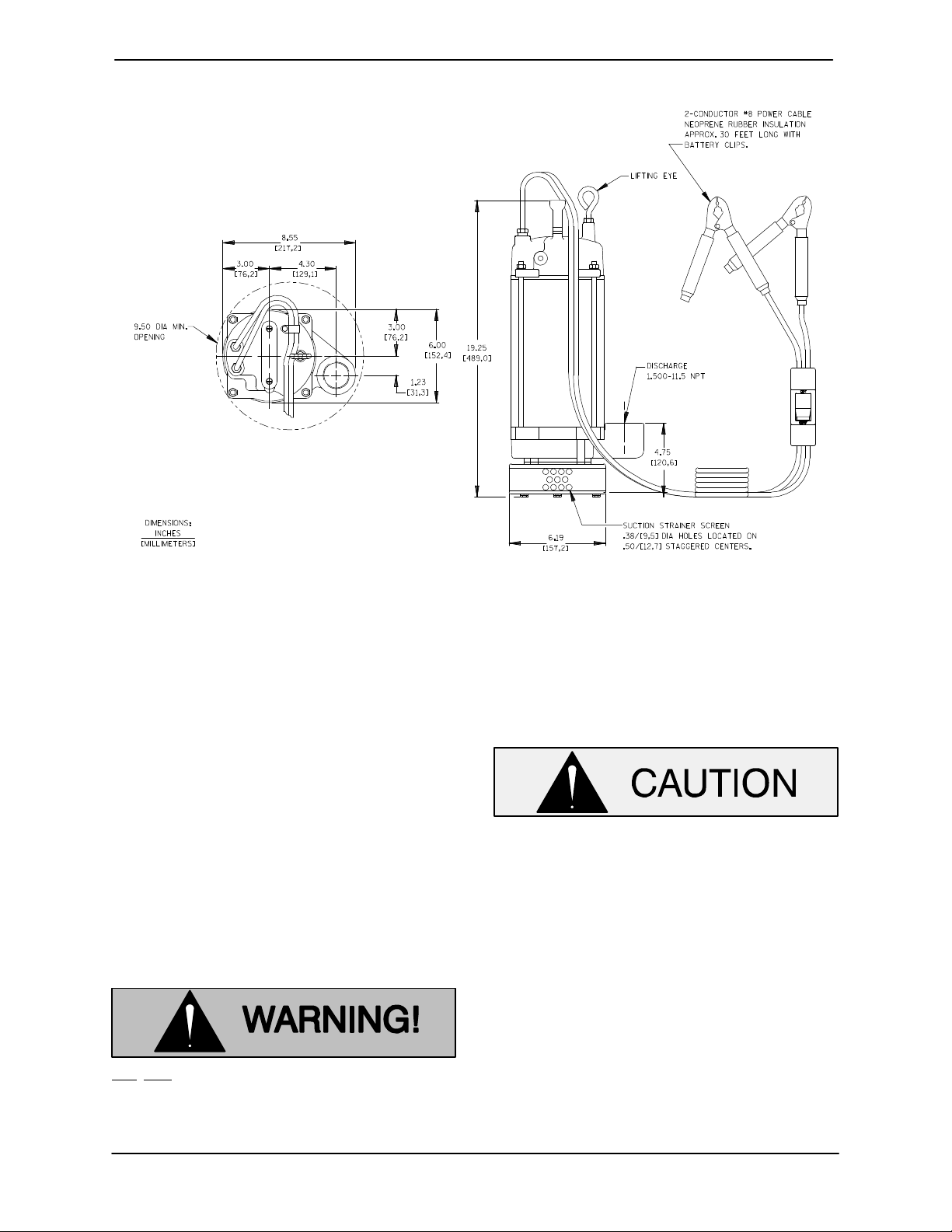
The pump is provided with a suction strainer to prevent large solids from clogging the impeller. See
Figure 1 for the approximate physical dimensions
of the pump.
PAGE B − 1INSTALLATION
Page 8
OM−06490 SE SERIES
OUTLINE DRAWING
TOP VIEW
Figure 1. Pump Model SE1 1/2B3−E.33 12V
Lifting
Pump unit weights will vary depending on the
mounting and drive provided. Check the shipping
tag on the unit packaging for the actual weight, and
use lifting equipment with appropriate capacity.
Drain the pump and remove all customer-installed
equipment such as suction and discharge hoses
or piping before attempting to lift existing, installed
units.
Attach a rope or chain to the lifting handle in the top
of the motor cover. Do not lift the unit by the power
cables or the discharge piping. Do not attach lifting
equipment to the carry handle. Customer installed
equipment such as rigid discharge piping must be
removed before attempting to lift.
Positioning the Pump
This pump is designed to operate fully or partially
submerged; however, it should not be operated
dry for extended periods of time.
Extended dry operation will destroy the
seal assembly.
Secure and support the pump by the lifting eye fitted on the pump. If the application involves a lot of
debris, protect the pump from excessive wear and
clogging by suspending it in a perforated barrel or
culvert pipe. If the bottom is heavily sludge-covered, rest the pump on support blocks or suspend
it from a raft or similar device near the surface of the
liquid. See Figure 2 for typical pump installations.
Do not attempt to lift the pump by the
power cables, carry handle or piping.
Attach proper lifting equipment to the
lifting eye fitted to the pump.
PAGE B − 2 INSTALLATION
The pump is provided with a suction strainer to prevent large solids from clogging the impeller. Any
spherical solids which pass through the strainer
will pass through the pump.
Page 9

OM−06490SE SERIES
BY BAIL
IN PERFORATED CULVERT PIPE
Figure 2. Typical Pump Installations
PIPING
The pump volute is equipped with a standard
1−1/2−inch NPT tapped discharge connection.
Either hose or rigid pipe may be used for the discharge connection.
For maximum pumping capacity, use non-collapsible hose or rigid piping, and keep the discharge as
short and straight as possible. If rigid piping is
used, minimize the use of elbows and fittings which
increase friction losses and reduce pump performance.
A check valve or throttling valve may be installed in
the discharge line to control siphoning or back flow
when the pump is shut off.
ON SUPPORTS
Never attempt to alter the length or repair any power cable with a splice. The
pump motor and cable must be completely waterproof. Damage to the pump
or personal injury may result from alterations.
When connecting the pump power cables to the
vehicle, first check the vehicle owner’s manual to
determine if the vehicle has a negative or a positive
grounding system.
PUMP POWER CABLE CONNECTIONS
The pump is provided with two 30-foot (3 m) power
cables. Splicing of the power cables is not recommended by the Gorman-Rupp Company due to
safety and warranty considerations.
Always make sure the switch on the
power cables is in the OFF position before connecting the leads to the vehicle
battery. Failure to do so could cause
arcing, resulting in explosion or fire.
Refer to Figure 3 for pump power cable connections, and proceed as follows:
PAGE B − 3INSTALLATION
Page 10

OM−06490 SE SERIES
1) Connect the red cable clamp from the pump
to the positive (+) terminal on negative
grounding systems, or to the negative (−) terminal on positive grounding systems.
Do not allow the pump and vehicle to
come into contact when connecting the
power cable to the battery. If the pump
should develop an internal short to the
casing, electrical shock could occur,
causing severe injury or death to personnel.
2) Connect the black cable clamp from the
pump to ground, preferrably to a solid, metallic, stationary point on the engine. The con-
nection should be made as far away from the
battery as possible.
BATTERY
Power
line to
VEHICLE ENGINE
Ground
(Black)
Ground line
from pump
pump
(Red)
HANDY-SUBT
Switch
PUMP
Figure 3. Pump Power Cable Connections
(Negative Ground System)
PAGE B − 4 INSTALLATION
Page 11

SE SERIES
OM−06490
OPERATION − SECTION C
Review all SAFETY information in Section A.
Follow the instructions on all tags, labels and
decals attached to the pump.
PUMP OPERATION
Do not operate this pump where explosive vapors or flammable material exist.
Death or serious injury will result.
Check the National Electric Code
(N.E.C.) and local codes before using.
This pump is designed to handle dirty
water that does not contain large entrained solids. It is not designed to
pump volatile, flammable or corrosive
materials. Do not attempt to pump any
liquids which may damage the pump or
endanger personnel as a result of pump
failure.
Install the pump and piping as described in INSTALLATION, Section B.
Running Time
The pump draws about 30 Amps, and can be operated for about 45 minutes on a fully-charged 55
AMP-hour battery, and still permit starting of the vehicle under normal conditions. Caution should be
used when the running time exceeds 30 or 40 minutes without the engine running to recharge the
battery, particularly in cold weather when the battery efficiency is lowered. Battery size (AMP-hour
rating) and the use of other accessories such as
the lights and radio, must be taken into consideration for practical running periods without the vehicle engine running.
Do not operate an internal combustion
engine in an explosive atmosphere.
When operating internal combustion
engines in an enclosed area, make certain that exhaust fumes are piped to the
outside. These fumes contain carbon
monoxide, a deadly gas that is colorless, tasteless, and odorless.
Overload Protection
Overload protection is provided by means of a 40
Amp automatic reset circuit breaker located inside
the motor cover on top of the pump.
Operational Checks
Check the pump for proper operation when it is first
Switching
The ON-OFF switch for the pump is located on the
power cable. With the switch in the OFF position, a
safety interlock circuit eliminates arcing when the
cable is connected to the battery. Arcing may occur if the switch was left ON because the pump was
stopped after its last operation by disconnecting
the battery clips without using the switch. Always
make sure the switch is in the OFF position before
connecting to the vehicle battery.
OPERATION PAGE C − 1
started and periodically thereafter to identify minor
problems.
Check the pump for unusual noises or excessive
vibration while it is operating. If noise or vibration is
excessive, stop the pump and refer to the
troubleshooting chart for possible causes.
Check the pump strainer screen for clogging
caused by stones, sticks, or other debris. Clean
the strainer screen when required. In some cases,
stopping the pump momentarily may back flush
Page 12

OM−06490
the strainer screen, purging most of the debris
from it. If this fails to clean the screen, remove the
pump from the sump and remove the debris manually (see MAINTENANCE AND REPAIR in Section
E).
Never introduce air or steam pressure into the
pump casing or piping to remove a blockage. This
could result in personal injury or damage to the
equipment. If backflushing is absolutely necessary, liquid pressure must be limited to 50% of the
maximum permissible operating pressure shown
on the pump performance curve (see MAINTE-
NANCE AND REPAIR, Section E).
SE SERIES
Do not attempt to lift the pump by the
power cables, carry handle or piping.
Attach proper lifting equipment to the
lifting eye fitted to the pump.
Clean the strainer screen before storage. If the
application involves a lot of mud or sludge, remove
the strainer and clean the impeller before storage.
NOTE
The most common cause of failure to run is hardened mud or sludge in the impeller.
STOPPING
After stopping the pump, be sure to perform all required maintenance and preservation procedures.
Storage and Cold Weather Preservation
After stopping the pump, disconnect the power
cables from the vehicle battery, and use the rope or
chain attached to the lifting eye on the motor cover
to remove the pump from the sump. Do not lift the
unit by the power cables or the discharge piping.
Do not attach lifting equipment to the carry handle.
Customer installed equipment such as rigid discharge piping must be removed before attempting
to lift.
In freezing temperatures, the pump will not freeze
as long as it is submerged in liquid. If the pump
casing is not submerged, or if the liquid begins to
freeze, remove the pump from the sump and allow
it to dry thoroughly. Run the pump for two or three
minutes to dry the inner walls.
If the pump freezes, move it into a warm area until
completely thawed, or submerge it into the liquid. If
the liquid is near freezing, the pump must be submerged for an extended period of time. Start the
pump and check for shaft rotation. If still frozen, allow additional thawing time before attempting to
restart.
Do not attempt to thaw the pump by using
a torch or other source of flame. This could
damage gaskets, electrical components,
or motor windings.
OPERATIONPAGE C − 2
Page 13

SE SERIES OM−06490
TROUBLESHOOTING − SECTION D
Review all SAFETY information in Section A.
TROUBLE POSSIBLE CAUSE PROBABLE REMEDY
MOTOR WILL NOT
RUN
MOTOR RUNS, BUT
PUMP FAILS TO
DELIVER RATED
DISCHARGE
Hardened mud or sludge in impeller. Remove strainer, check and clean.
Poor connection at battery or vehicle Check and correct connections.
ground.
Impeller binding. Check freedom of rotation. Add shims
or gaskets as required.
Damaged power cable(s). Inspect and replace as required.
Open circuit in motor windings or power Check continuity.
cable.
Loose connection in motor cover. Remove cover, check connections
and correct as required.
Bad switch or circuit breaker. Check electrical components as
described in this section and replace
as required.
Worn motor brushes or out of position Disassemble pump, check and
to make contact with armature. replace brushes as required.
Strainer clogged. Check and clean as required.
Impeller binding. Check freedom of rotation. Add shims
or gaskets as required.
Discharge line clogged or restricted; Check discharge lines; straighten
hose kinked. hose.
Liquid being pumped too thick. Dilute liquid by heating if possible.
Vehicle battery not fully charged. Start vehicle and allow to run until
battery is fully charged.
Worn impeller vanes; excessive impeller Check impeller and clearance. See
clearance. PUMP END REASSEMBLY.
Pumping entrained air. Check liquid level in sump; check
position of pump.
Damaged or unbalanced impeller. Replace impeller.
TROUBLESHOOTING PAGE D − 1
Page 14

OM−06490
TROUBLE POSSIBLE CAUSE PROBABLE REMEDY
SE SERIES
PUMP RUNS WITH
EXCESSIVE NOISE
OR VIBRATION
Pumping entrained air. Check liquid level in sump; check
Damaged impeller. Inspect and replace impeller.
Motor shaft or bearings defective. Disassemble pump and check motor
ELECTRICAL TESTING
If you suspect that pump malfunctions are caused
by defects in the power cables or electrical components, perform the following checks to help isolate
the defective part.
Obtain the services of a qualified electrician to troubleshoot, test and/or service the electrical components of this
pump.
position of pump.
and bearings.
Power Cable Continuity Check
Disconnect the power cables inside the motor cover. Use the ohmmeter to check continuity of the
cables, and replace defective cables as required.
Never attempt to alter the length or repair any power cable with a splice. The
pump motor and cable must be completely waterproof. Damage to the pump
or personal injury may result from alterations.
Always disconnect the battery clamps
from the vehicle battery when testing electrical components.
Test Equipment
A volt/amp/ohmmeter of adequate range and quality will be required to conduct the following electrical tests.
Equipment Use
Ammeter To check AC Voltage
and current (amperage)
Ohmeter To measure resistance
(ohms) to ground
Circuit Breaker Check
The circuit breaker used in this pump is normally
closed. Disconnect the wires from the breaker, and
check continuity across the terminals. If the circuit
is open, replace the breaker.
On-Off Switch Check
Disconnect red battery cable lead from circuit
breaker terminal. Check continuity between battery clamp and ring terminal on the end of the
cable. Moving ON-OFF switch from ON to OFF
should break continuity. If the switch is bad, the
continuity will remain open when the switch is in
the ON position.
TROUBLESHOOTINGPAGE D − 2
Page 15

SE SERIES OM−06490
PUMP MAINTENANCE AND REPAIR - SECTION E
MAINTENANCE AND REPAIR OF THE WEARING PARTS OF THE PUMP WILL MAINTAIN PEAK
OPERATING PERFORMANCE.
STANDARD PERFORMANCE FOR PUMP MODEL SE1 1/2B3−E.33 12V
Based on 70_ F (21_ C) clear water at sea level.
Since pump installations are seldom identical, your
MAINTENANCE & REPAIR PAGE E − 1
performance may be difference due to such factors as viscosity, specific gravity and temperature.
Page 16

OM−06490 SE SERIES
SECTION DRAWING
PARTS PAGE
Figure 1. Pump Model SE1 1/2B3−E.33 12V
MAINTENANCE & REPAIRPAGE E − 2
Page 17

SE SERIES OM−06490
PARTS LIST
Pump Model SE1 1/2B3−E.33 12V
(From S/N 1483930 Up)
If your pump serial number is followed by an N", your pump is NOT a standard production model. Contact
the Gorman-Rupp Company to verify part numbers.
ITEM
PART NAME PART
NO.
NUMBER
MAT’L
CODE
QTY ITEM
NO.
PART NAME PART
NUMBER
MAT’L
CODE
QTY
1 CASING TUBE KIT 26831−071 −−− 1
1A −CASING TUBE NOT AVAILABLE 1
1B −STUD NOT AVAILABLE 4
2 O-RING 25152−254 −−− 1
3 LOCK WASHER J04 15991 4
4 HEX HD CAPSCREW B0403−1/2 15991 4
5 PUMP CASING 26831−072 −−− 1
6 SEAL ASSY 26831−003 −−− 1
7 IMP ADJ SHIM 26831−061 −−− 7
8 IMPELLER 26831−002 −−− 1
9 CASING GASKET 26831−062 −−− 5
10 SUCTION COVER 26831−076 −−− 1
11 STRAINER 26831−064 −−− 1
12 STRAINER PLATE 26831−065 −−− 1
13 LOCK WASHER J04 14991 4
14 HEX HD CAPSCREW B0411 17000 4
15 MOTOR 26831−075 −−− 1
16 POWER CABLE ASSY 26831−073 −−− 1
17 O-RING 25152−254 −−− 1
18 MOTOR COVER 26831−074 −−− 1
19 HEX NUT D06 15991 1
20 HANDLE 26831−052 −−− 1
INDICATES PARTS RECOMMENDED FOR STOCK
21 LOCK WASHER J#10 15991 1
22 RD HD MACH SCREW X#04−02 15991 1
23 CABLE CLAMP 26831−007 −−− 1
24 GLAND NUT 26831−022 −−− 2
25 GLAND SPACER 26831−023 −−− 2
26 SEALING RING 26831−024 −−− 2
27 HEX NUT D05 15991 4
28 LOCK WASHER J05 15991 4
29 TWIST TYPE CONNECTOR26831−078 −−− 1
30 RING TERMINAL 26831−077 −−− 1
31 CIRCUIT BREAKER 26831−042 −−− 1
32 SELF-TAPPING SCREW 26831−035 −−− 2
NOT SHOWN:
MOTOR BRUSH 26831−079 −−− 2
CAUTION DECAL (LARGE) 26831−068 −−− 1
NAMEPLATE 38812−073 −−− 1
G-R DECAL GR−03 −−− 1
CAUTION DECAL 26831−081 −−− 2
OPTIONAL:
CARRYING CASE/HOSE KIT 48782−001 −−− 1
MAINTENANCE & REPAIR PAGE E − 3
Page 18

OM−06490 SE SERIES
PUMP AND SEAL DISASSEMBLY AND REASSEMBLY
Review all SAFETY information in Section A.
Follow the instructions on all tags, label and decals attached to the pump.
The following maintenance and repair instructions
are keyed to the Pump Model sectional view (Figure 1) and the accompanying parts lists.
Before attempting to service the pump, switch off
the pump and disconnect the power cables from
the vehicle battery to ensure that the pump will remain inoperative.
Before attempting to open or service the
pump:
1. Familiarize yourself with this manual.
2. Switch off the pump and disconnect the power cables from the vehicle battery to ensure that the
pump will remain inoperative.
3. Allow the pump to cool if overheated.
Use a rope or chain attached to the handle in the
motor cover to remove the pump from the sump,
and move it to a location where the discharge line
can be removed. It is not necessary to disconnect a
flexible discharge hose before removing the pump.
If rigid discharge piping is used, disconnect the
piping before attempting to move the pump.
motor housing is to be opened, the work must be
done in a clean, well-equipped shop. All maintenance functions must be done by qualified personnel.
Obtain the services of a qualified electrician to troubleshoot, test and/or service the electrical components of this
pump.
Check the chart in TROUBLESHOOTING, Section
D, to determine the nature of the pump problem. If
the problem is mechanical in nature, such as worn
pump parts, seal replacement, etc., refer to PUMP
END DISASSEMBLY for instructions.
If the problem is electrical, complete disassembly
may not be required. Refer to Electrical Testing in
TROUBLESHOOTING, Section D, and have a
qualified electrician check the cables and electrical
components inside the motor cover. If the problem
is determined to be in electrical components, complete disassembly of the pump may not be required. See the appropriate section in MOTOR
DISASSEMBLY.
Carefully inspect any O-rings or gaskets before removal and cleaning to determine if a proper seal
and compression existed prior to disassembly. If
sealing was faulty or questionable, the cause must
be determined and corrected before reassembly.
All gaskets and most O-rings must be replaced if
disturbed. Repair gaskets and O-rings are listed on
the parts list.
Do not attempt to lift the pump by the
power cables, carry handle or piping.
Attach proper lifting equipment to the
lifting eye fitted to the pump.
Select a suitable location, preferably indoors, to
perform the degree of maintenance required. If the
PUMP END DISASSEMBLY
Strainer Removal
To remove the strainer screen (11), lay the pump
on its side and disengage the hardware (13 and
14). Remove the strainer plate (12), strainer
screen, suction cover (10) and casing gaskets (9).
If the impeller is clogged, the debris can usually be
removed without further disassembly.
MAINTENANCE & REPAIRPAGE E − 4
Page 19

SE SERIES OM−06490
Impeller Removal
Wedge a piece of wood between the vanes of the
impeller (8) and the inside of the pump casing (5).
Insert a large flat-bladed screwdriver into the slot in
the end of the shaft. Turn the shaft in a clockwise
direction to break the impeller loose. After the impeller breaks loose, remove the screwdriver and
wood block and unscrew the impeller from the
shaft. Use caution when unscrewing the impeller;
tension on the seal spring will be released.
Remove the impeller shims (7). For ease of reassembly, tie and tag the shims or measure and record their thickness.
Seal Removal
(Figures 1 and 2)
Remove the spring centering washer and spring.
Lubricate the seal area of the rotor shaft with light
oil. To easily remove the seal, disengage the hardware (3 and 4) securing the pump casing to the
motor (15). Use a soft-faced mallet to tap the pump
casing loose from the casing tube (1A).
Slide the pump casing and seal off the shaft. Press
the stationary portion of the seal out of the pump
casing from the back side.
Inspect the lower casing tube O-ring (2). If replacement is required, remove it from the pump casing.
If no further disassembly is required, proceed with
PUMP END REASSEMBLY.
NOTE
Do not disassemble the motor unless it is necessary and a clean, well-equipped shop is available. If
the motor housing components are to be serviced,
see MOTOR DISASSEMBLY in this section. Do not
reassemble the end components at this time.
during reassembly (see the parts lists for numbers).
Cleaning And Inspection Of Pump Parts
Carefully inspect any O-rings or gaskets before removal and cleaning to determine if a proper seal
and compression existed prior to disassembly. If
sealing was faulty or questionable, the cause must
be determined and corrected before reassembly.
Replace any parts as required.
Thoroughly clean all reuseable parts with a soft
cloth soaked in cleaning solvent. Remove all Orings and gaskets, and clean the sealing surfaces
of dirt or gasket material. Be careful not to scratch
gasket surfaces.
Most cleaning solvents are toxic and
flammable. Use them only in a well-ventilated area free from excessive heat,
sparks, and flame. Read and follow all
precautions printed on solvent containers.
Inspect the rotor shaft for damaged threads, scoring, or nicks. Remove nicks and burrs with a fine
file or emery cloth to restore original contours. If the
shaft is bent or severely damaged, the motor must
be replaced as an assembly (see MOTOR DISAS-
SEMBLY).
Inspect the seal components for wear, scoring,
grooves, and other damage that might cause leakage. The shaft seal assembly should not be reused
because wear patterns on the finished faces cannot be realigned during reassembly. This could result in premature failure. If any components are
worn, replace the complete seal; never mix old
and new seal parts.
Handle a new seal with extreme care to prevent
PUMP END REASSEMBLY
NOTE
Reuse of old O-rings, gaskets, or shaft seal parts
may result in premature leakage or reduced pump
performance. It is strongly recommended that new
gaskets and a new shaft seal assembly be used
MAINTENANCE & REPAIR PAGE E − 5
damage. Be careful not to contaminate the precision finished faces; even fingerprints on the faces
can shorten seal life. If necessary, clean the faces
with a non-oil based solvent and a clean, lint-free
tissue. Wipe lightly in a concentric pattern to avoid
scratching the faces.
Install the shaft seal as illustrated in Figure 2.
Page 20

OM−06490 SE SERIES
STATIONARY
CUP SEAT
BELLOWS
SPRING
CENTERING
WASHER
PUMP
CASING
STATIONARY
ELEMENT
ROTATING
ELEMENT
ROTOR
SHAFT
BELLOWS
RETAINER
SPRING
IMPELLER
SHIMS
IMPELLER
Figure 2. Seal Assembly
Seal Installation
(Figures 1 and 2)
If a new seal assembly is to be installed, do not unwrap it until time of installation. Cleanliness of seal
components is critical, especially the seal faces.
Clean the rotor shaft and seal cavity area of the
pump casing (5). Be sure the area is dry and free of
lint and dirt. Check the seal bore for burrs or nicks
that might prevent a good seal. Apply a light coating of oil to the bore.
NOTE
When pressing seal components onto the shaft,
use hand pressure only. A push tube cut from a
length of plastic pipe will aid in installing seal components. The I.D. of the push tube should be approximately the same as the I.D. of the seal spring.
thumbs to press the assembly into the bore. Apply
equal pressure on opposite sides until the seat
contacts the bore shoulder. Remove the tissue and
inspect the seal face to ensure that it is clean and
dry. If cleaning is necessary, use a clean lint-free
cloth to wipe lightly in a concentric pattern.
Lubricate and install a new casing tube O-ring (2)
on the pump casing. Carefully slide the pump casing over the shaft and use a soft-faced mallet to tap
the casing into the casing tube (1A) until fully
seated. Secure the pump casing to the motor with
the hardware (3 and 4).
Be certain the seal face of the rotating element is
free of grit or surface damage. Apply a light coating of oil to the seal seating surface on the shaft
and the I.D. of the bellows. Inspect the seal face to
ensure that it is clean and dry. If cleaning is necessary, use a clean lint-free cloth to wipe in a concentric pattern.
Subassemble the stationary element in the stationary cup seat. Position this subassembly in the casing bore with the sealing face up, and cover the
seal face with a clean, lint-free cloth. Use your
Slide the seal rotating portion onto the lubricated
shaft as shown in Figure 2. Apply firm, steady pressure on the seal retainer until it slides down the
shaft.
MAINTENANCE & REPAIRPAGE E − 6
Page 21

SE SERIES OM−06490
Slide the seal spring over the shaft and bellows retainer, and install the spring centering washer. See
Figure 2 for the proper order of seal assembly.
Impeller Installation
Inspect the impeller (8) for cracks, broken vanes,
or wear from erosion, and replace it if damaged.
Clean the threads on the rotor shaft.
Install the same thickness of impeller adjusting
shims (7) as previously removed. Position the impeller against the shims and seal spring. Carefully
compress the spring with the impeller until the impeller can be started on the shaft threads. Screw
the impeller onto the shaft until it is fully seated.
Wedge a piece of wood between the vanes of the
impeller and the inside of the pump casing.
Insert a large flat-bladed screwdriver into the slot in
the end of the shaft. Turn the shaft in a counter-
clockwise direction to secure the impeller.
Remove the block of wood, and turn the impeller to
check for free rotation. If the impeller scrapes or
binds against the pump casing, remove the impeller and install additional shims as required. Reinstall the impeller and re-check the clearance.
MOTOR DISASSEMBLY
Disassembly of the motor is rarely required except
to replace electrical components or the motor
brushes. Do not disassemble the motor unless it is
necessary and a clean, well-equipped shop is
available.
NOTE
It is recommended that a pump with a defective motor be returned to Gorman-Rupp, or to one of the
Gorman-Rupp authorized Submersible Repair
Centers.
Obtain the services of a qualified electrician to troubleshoot, test and/or service the electrical components of this
pump.
Carefully inspect any O-rings or gaskets before removal and cleaning to determine if a proper seal
and compression existed prior to disassembly. If
sealing was faulty or questionable, the cause must
be determined and corrected before reassembly.
Replace any parts as required.
Check front impeller clearance after installing the
suction cover (10).
Strainer Installation
Inspect the strainer screen (1) and suction cover
(10) for cracks, distortion or erosion, and replace
any defective parts.
Install the same thickness of casing gaskets (9)
and position the suction cover against the gaskets.
Insert a flat-bladed screwdriver in the slot in the end
of the shaft, and turn the shaft to check for scraping
or binding. If scraping or binding occurs, install
additional gaskets.
Install the suction cover, strainer screen and strainer plate (12) and secure the parts with the hardware (13 and 14).
MAINTENANCE & REPAIR PAGE E − 7
Cable Assembly and Motor Cover Removal
Total removal of the motor assembly (15) is not always required. Disassemble and replace only the
parts proven defective by inspection or testing.
See Electrical Testing in TROUBLESHOOTING.
The electrical components may be serviced without disassembling the motor housing or pump
end.
Secure the pump in an upright position. To remove
the motor cover, disengage the hardware (27 and
28). Use a screwdriver to carefully pry the motor
cover out of the casing tube.
Carefully raise the motor cover until the electrical
components are accessible. To remove the motor
cover, unscrew the nut securing the red (positive)
power cable lead to the shorter terminal on the circuit breaker (31).
Page 22

OM−06490 SE SERIES
Unscrew the twist-type connector (29) securing
the black (negative) power cable lead to the red
motor lead. Separate the motor cover from the casing tube.
Remove the O-ring (17) from the groove in the motor cover.
To remove the power cable assembly (16), remove
the hardware (21 and 22) securing the cable clamp
(23) to the motor cover. Unscrew the gland nuts
(24) from the motor cover and pull the cables,
spacers (25) and sealing rings (26) from the motor
cover. Slide the cable clamp, sealing rings,
spacers and gland nuts off the power cables.
See Motor Cover Installation if no further disassembly is required.
Motor Circuit Breaker Removal
If electrical testing indicates a defective circuit
breaker (31), disconnect the red motor cable lead
and the red power cable lead from the circuit
breaker. Remove the self-tapping screws (32) securing the circuit breaker to the motor.
Motor Brush Removal
With the motor cover removed, the brushes (not
shown) can be easily removed. Remove the two
capscrews (not shown) in the top of the motor assembly and pry the motor casing open.
Reposition the previously separated motor casing
parts. Use caution not to pinch the motor leads and
to make sure the split grommet is properly positioned in the slot in the motor casing. Secure the
motor casing parts with the previously removed
capscrews.
Motor Circuit Breaker Installation
Secure the replacement circuit breaker (31) to the
top of the motor assembly with the self-tapping
screws (32). If a new motor assembly is being
installed, crimp the ring terminal (30) to the black
motor cable lead.
Secure the ring terminal on the black motor cable
lead to the longer terminal on the circuit breaker
with the previously removed nut.
Cable Assembly and Motor Cover Installation
If the cable assembly (16) was removed for replacement, slide the gland nuts (24), spacers (25)
and sealing rings (26) up the ends of the cable
leads approximately 12 inches (305 mm). Feed the
cable leads down through the holes in the motor
cover (18).
Lightly lubricate the upper casing tube O-ring (17)
and install it in the groove in the motor cover.
Refer to the wiring diagram in Figure 3, and use the
wire nut (29) to secure the black motor lead to the
black cable lead. Secure the ring terminal on the
red motor cable lead to the shorter terminal on the
circuit breaker with the previously removed nut.
Disengage the two small screws securing the
brush leads to the motor and remove the brushes.
There are no provisions for replacing motor parts.
Individual motor parts are not sold separately. If the
motor is damaged, the complete motor assembly
must be replaced. See the parts list on page E−3
for replacement parts.
MOTOR REASSEMBLY
Motor Brush Installation
Position the new brushes (not shown) in the brush
holders and secure the brush leads to the motor
assembly with the two previously removed screws.
RED BATTERY
RED
MOTOR
BLACK
AUX. BATT.
CIRCUIT BREAKER
(BLACK MOTOR LEAD
TO LONG TERMINAL)
WIRE
NUT
SWITCH
CLAMP
BLACK BATTERY
CLAMP
(GROUND)
Figure 3. Wiring Diagram
With the pump end components installed and the
casing tube (1A) in place, carefully pull the excess
cable leads up through the holes in the motor cover.
MAINTENANCE & REPAIRPAGE E − 8
Page 23

SE SERIES OM−06490
Position the motor cover in the casing tube with the
studs (1B) through the holes in the motor cover.
Install the hardware (27 and 28) and tighten the
nuts (27) in an alternating pattern until the motor
cover is fully seated in the casing tube. Use caution
not to cut or pinch the casing tube O-ring.
Slide the sealing rings (26) down the cable leads
and into the bores in the motor cover. Slide the
spacers (25) down the leads onto the sealing rings.
Screw the gland nuts (24) into the motor cover to
seal the cables.
Secure the cable leads to the motor cover with the
cable clamp (23) and hardware (21 and 22).
If removed, reinstall the lifting handle (20) and secure it with the jam nut (19).
Proceed with PUMP END REASSEMBLY.
MAINTENANCE & REPAIR PAGE E − 9
Page 24

For U.S. and International Warranty Information,
Please Visit www.grpumps.com/warranty
or call:
U.S.: 419−755−1280
International: +1−419−755−1352
For Canadian Warranty Information,
Please Visit www.grcanada.com/warranty
or call:
519−631−2870
THE GORMAN-RUPP COMPANY D MANSFIELD, OHIO
GORMAN-RUPP OF CANADA LIMITED D ST. THOMAS, ONTARIO, CANADA
 Loading...