

Page 1
8
A
7
B
C
6532 4
ENGLISH
MDE-LEDI-NETWORK-TDS-4099V1.0
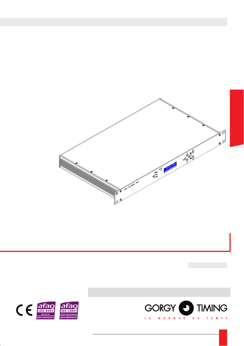
LEDI® NETWORK TDS V1
TIME SERVER
USER MANUAL
1
Page 2
IMPORTANT SAFETY INSTRUCTIONS
WARNING! The following section provides the safety instructions for the installation. Please
read it carefully before installing your device.
To protect your device, connect power on UPS (Uninterruptible Power Supply).
The device must be connected to an electrical installation complying with the NF C15-100
standard.
The wiring installation must include an easily accessible power protection system (circuitbreaker or disconnecting switch) compatible with the nominal voltage and current values
specied on the device.
In Europe: in accordance with European regulations on the protection of the people and the
environment, this device must be disposed of in a collection site designed for this purpose
(separately from household waste). Please contact your reseller, collection site or the competent local authorities for more information.
Modifying or opening the product without the consent of the Customer service department
will void the warranty.
The
LEDI® NETWORK TDS V1
a competent person.
must be installed, maintained and manipulated only by
All maintenance operation shall be conducted with power shut off, including on systems
connected to relay outputs if any.
Generally, the power cable (230V) and transmission cable (of time signal) should not be
too close to each other so as to avoid interferences (keep a distance of a few centimeters).
The
LEDI® NETWORK TDS V1
(speakers, antennas, high frequency equipment, electromagnetic alarms…) in order to avoid
electric interferences.
Gorgy Timing disclaims all liability in case of accident or damage caused by an improper use
of the
LEDI® NETWORK TDS V1
All GORGY TIMING products comply with the following standards: CE, EN60950-1, EN55022
class B, EN50024
2
must be located as far as possible from radiation sources
.
MDE-LEDI-NETWORK-TDS-4099V1.0
Page 3
NOTICE OF SAFETY SIGNS ON THE PRODUCT
General danger – ignoring the instructions may cause damage to the equipment.
Electrical Hazard – ignoring the instructions may result in electric shock and injury.
The equipment is completely protected through double insulation.
Warning
Please follow the precautions and instructions as indicated below in order to ensure your safety and
that of your environment, and to prevent any potential damage to your device.
Warning: a Switch-Isolator complying with the EN60947 standards is used as a disconnecting device. It must be easily accessible and be installed close to the power cable. It must
disconnect all active polarities.
The LEDI® NETWORK TDS V1 is intended for indoors use only, at an altitude below 2000
meters.
Waste disposal by users in private households in countries of the European Union
This symbol on the product or the packaging indicates that the product must not be disposed
of into household waste. Instead, it is your responsibility to bring the waste to a collecting
station specically designed for recycling electric and electronic components. The separate
collection and recycling of your waste will contribute to the conservation of natural resources
and to ensure a safe, environmental and health friendly recycling. For more information
about the nearest recycling site, please contact the store where the device was purchased,
the waste disposal services or the competent local authorities.
Technical features
Power supply
Dimensions
Operating conditions
ENGLISH
Voltage 230Vac
Frequency 50-60Hz
Current 0,1 A Max
Length 482 mm
Width 266 mm
Height 44 mm
Maximum operating temperature 50°C
Humidity (non-condensed) 90 %
MDE-LEDI-NETWORK-TDS-4099V1.0
3
Page 4

SUMMARY
1. INTRODUCTION ............................................................................................................ 6
2. QUICKSTART ................................................................................................................ 7
3. SETTING UP THE SERVER, GENERAL INFORMATION ............................................ 8
3.1. MANUAL NETWORK CONFIGURATION ............................................................................ 8
3.2. OUTPUT CARDS CONFIGURATION .................................................................................. 8
3.3. ALARMS SETTINGS ........................................................................................................... 8
3.4. NTP PROTOCOL GENERAL INFORMATION ..................................................................... 9
3.5. GENERAL FACTS ABOUT SYNCHRONIZATION ............................................................. 10
3.6. OPERATING MODES OF THE LEDI® NETWORK TDS V1 ............................................... 10
4. FRONT LCD DISPLAY ..................................................................................................11
4.1. STARTUP ............................................................................................................................11
4.2. TIME DISPLAY ................................................................................................................... 12
4.3. ALARM CONDITIONS ........................................................................................................ 13
4.4. MANUAL IPV4 / IPV6 SETTINGS ...................................................................................... 14
4.4.1. Display current IP addresses .................................................................................. 14
4.4.2. Change the IP settings ........................................................................................... 14
4.4.3. IPv4 ........................................................................................................................ 15
4.4.4. IPv6 ........................................................................................................................ 17
4.5. RESTART UNIT .................................................................................................................. 19
5. WEB INTERFACE ........................................................................................................ 20
5.1. Presentation ....................................................................................................................... 20
5.2. Web interface description ................................................................................................... 20
5.2.1. Navigation menu .................................................................................................... 20
5.2.2. "Index" page ........................................................................................................... 23
5.2.3. "Network" page ....................................................................................................... 25
5.2.4. "Alarms" page ......................................................................................................... 27
5.2.5. "SNMP" page .......................................................................................................... 29
5.2.6. "NTP" page ............................................................................................................. 31
5.2.7. "Input" page ............................................................................................................ 36
5.2.8. "Output" page ......................................................................................................... 40
5.2.9. INTERFACE page ..................................................................................................45
A. User Accounts ....................................................................................................... 45
B. Front LCD ............................................................................................................... 46
C. Other interfaces ...................................................................................................... 46
D. Restart button ......................................................................................................... 50
5.2.10. UPDATE page ......................................................................................................50
5.2.11. “Diagnostics” page ............................................................................................... 53
4
MDE-LEDI-NETWORK-TDS-4099V1.0
Page 5

6. APPENDIX A – CONNECTIONS ................................................................................. 55
6.1. DCF-GPS ANTENNA ......................................................................................................... 56
6.1.1. DCF Antenna Réf : 3D6 (four meters cable included) ............................................ 56
6.1.2. Gps ANTENNA CONVERTER UNIT ..................................................................... 56
6.2. AFNOR-NFS-87500 / IRIG-B OUTPUT .............................................................................. 58
6.3. SERIAL IMPULSION OUTPUT ..........................................................................................58
7. APPENDIX B – OUTPUT CODES FORMAT ............................................................. 59
8. APPENDIX C – MAINTENANCE ................................................................................. 61
8.1. CARD REPLACEMENT + IMPULSION CARD POWER .................................................... 61
8.2. MICROCONTROLERS REPLACEMENT .......................................................................... 62
8.3. OUTPUT CARDS ADDRESSES SWITCHES ....................................................................63
8.4. TOP & IRIG B DCLS TIME CODE OUTPUT ...................................................................... 64
8.5. SUPERVISION PROTOCOLS............................................................................................ 65
9. APPENDIX D – FIXES ................................................................................................. 66
ENGLISH
MDE-LEDI-NETWORK-TDS-4099V1.0
5
Page 6
1. INTRODUCTION
8
A
7
B
C
6532 4
D
E
1
44
This document is the user manual for the LEDI® NETWORK TDS V1. This product is an
accurate and easily congurable time server.
It synchronizes through an NTP Ethernet 10/100 base T or DCF or GPS time input.
There are 3 available outputs: AFNOR NFS 87500 / IRIG B, IMPULSION, NTP.
The server communicates through the following network protocols:
► IPv4 et v6
► HTTP(S)
► SNMP
► Telnet
► FTP
► SMTP
► Syslog
► (S)NTP
► SSH
The security features ensure that the server only delivers reliable and continuous timing
information.
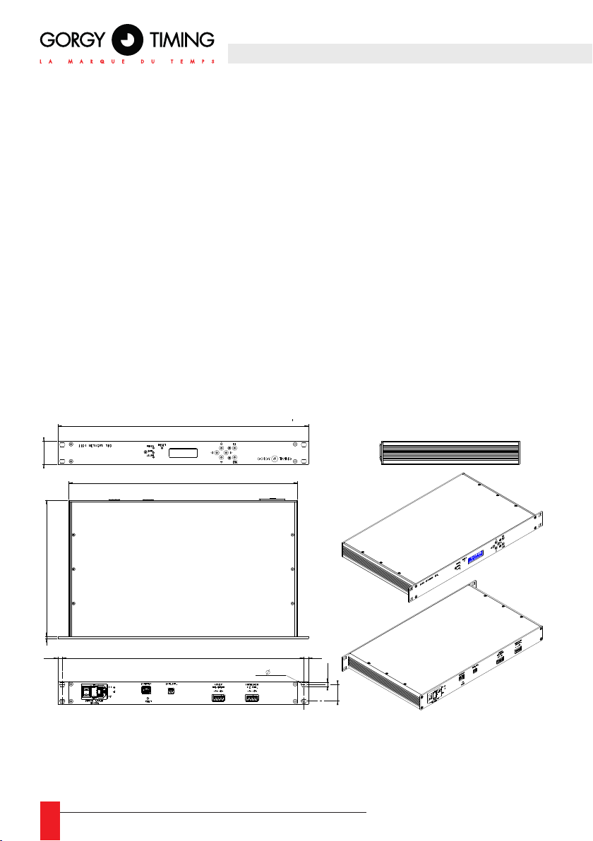
Dimensions
LEDI® NETWORK TDS V1 Rack
482
440
2633
8,7 8,7
464,6
4x 10,5
4x7,5
31,75
6
MDE-LEDI-NETWORK-TDS-4099V1.0
Page 7

2. QUICKSTART
CONTENT OF THE PACKAGE
Upon delivery, the box should contain the following elements:
► The 19" rack, bearing the mention ”LEDI® NETWORK TDS”
► A C13 power supply cable without locking
► An RJ45 Network cable
► A DVD-ROM that contains software and documentation
☛ Please contact the customers service if one of the items above is
missing
CONNECTING THE SERVER
It may be useful to write down the serial number written on the identication stamp of the
1u 19” rack.
► Connect the synchronization outputs to the devices to be synchronized (see Appen-
dix A – Connections).
► Connect the LEDI® NETWORK TDS V1 server to the network using the network
cable.
NOTE: It is possible to connect the server directly to a computer using a
crossed network cable for settings/tests purposes.
ENGLISH
► Connect the power supply cable to the server and switch ON to start it.
► The servers starts. The process may take up to one minute.
NOTE: initialization of the server is slower and may take up to three minutes
if there is no network cable connected.
► By default, the server is set up to get its IPv4 and IPv6 addresses from a DHCP
server. If such a server is present on the network, the LEDI® NETWORK TDS V1 is
can be accessed directly. Press any arrow key to display the IP Addresses on the
server’s LCD front screen.
► The GT Network Manager software (available on the DVD-ROM) can also detect
the server on the network and display the IP addresses.
MDE-LEDI-NETWORK-TDS-4099V1.0
7
Page 8

3. SETTING UP THE SERVER,
GENERAL INFORMATION
3.1. MANUAL NETWORK CONFIGURATION
By default, the server obtains its IPv4 and IPv6 addresses from a DHCP server.
There are several ways to manually modify IPv4 and IPv6:
► By accessing the web interface, in the « Network » page. (See section 5.2.3. “Page
Network")
► By using the front buttons (See section 4.4.2. “IPv4" )
► By using the Telnet and SSH consoles (See section 5.2.9. “INTERFACE page")
Additionally, the server will automatically take an IP address in the 169.254.0.0/16 and
fe80::/10 pre-dened scopes. The IP addresses of the LEDI® NETWORK TDS V1 can be
displayed at any time by pressing any of the arrow keys on the front panel.
3.2. OUTPUT CARDS CONFIGURATION
The default conguration for all the output cards is to deliver UTC time and only when the
server is synchronized.
For most of the output boards, it is possible to modify the output time code format, time
zone and DST policy.
These settings can be modied in section 5.2.8. "Output Page".
3.3. ALARMS SETTINGS
► The LEDI® NETWORK TDS V1 has an embedded alarm system than can alert the
administrators in case of need.
► The LCD front screen displays the current alarms messages and its backlight blinks to
indicate that at least one alarm condition is happening.
► SNMP traps can be sent to one or several supervision stations.
► The server can send e-mails with details on the situation.
► The server can send Syslog frames to one or two servers.
► Le serveur peut envoyer des trames Syslog à un ou deux serveurs.
These three features can be congured in the « SNMP » and « Alarm » webpages (See
sections 5.2.4. “ALARMS Page" and 5.2.5. “SNMP page").
8
MDE-LEDI-NETWORK-TDS-4099V1.0
Page 9

3.4. NTP PROTOCOL GENERAL INFORMATION
NTP (Network Time Protocol) is a network protocol designed to synchronize a device (the
client) with a time reference (the server). The LEDI® NETWORK TDS V1 is a server that
can synchronize numerous client devices from a main time source and optionally a client
capable of synchronizing on several servers.
In client/server mode, the client queries the server who answers with a time message. The
analysis of the transit times allows to determine the time difference between the client and
the server, thus deducing the appropriate correction.
Query server date
Receive reply date
client side server side
Network
Return current server date
NTP Exchange
In broadcast mode, the server periodically sends a time output on the network that is
received and used by NTP clients. This mode is bandwidth saving but less accurate5 than
the Client/ Server mode since the transit times are not compensated.
► The time distribution using the NTP protocol is always done in the UTC time format.
Time zones and DST must be set up on client sides.
► The NTP protocol can be used with MD5 hashes to authenticate the timing information.
The client and the server must use the same secret key and same key index (see section "5.2.6. “NTP” page").
ENGLISH
MDE-LEDI-NETWORK-TDS-4099V1.0
9
Page 10

3.5. GENERAL FACTS ABOUT SYNCHRONIZATION
The synchronization is the process during which, a local clock (internal) will be tuned by
aligning on a distant clock (the reference).
A local clock works with a reference frequency signal generated by an oscillator. The LEDI®
NETWORK TDS V1 uses a thermally compensated oscillator (TCXO).
► The offset is the instantaneous difference between two clocks.
► The drift is the late or advance that is taken by an oscillator as a consequence of its
imperfection. The better the oscillator, the lower the drift.
3.6. OPERATING MODES OF THE LEDI® NETWORK TDS V1
► Not synchronized: no available time input. The server does not have the correct time
and does not deliver time on its outputs.
► Autonomous: the server has been synchronized, but the input is no longer available. It
still has autonomy and keeps distributing time.
► Free Running: The server has been manually forced to run in autonomous mode (time
may have been set by the user). It delivers time on its outputs.
► Synchronized: The server is locked on a synchronization source. It delivers time on its
outputs.
10
MDE-LEDI-NETWORK-TDS-4099V1.0
Page 11

4. FRONT LCD DISPLAY
The front display interface can display up to 4 lines of 20 characters. Six buttons enables
the user to navigate in the menus and change some settings.
► A RESET button allows to restart the device except for the GPS input card.
► A POWER button lights up when the device is under power.
► A SYNC button lights up when the device is synchronized. It turns off when the device is
unsynchronized even if it has battery left.
► An ALARM button blinks when the device is not operating properly (e.g. synchronization
or power loss).
4.1. STARTUP
During start-up, the LCD screen displays the message “Init…” until the embedded software
starts and displays the loading advancement of the various software modules:
ENGLISH
Init . . .
LEDI NETWORK TDS V1
v18.106
*- *********** -*
*-USER INTERFACES -*
The rmware version is displayed on the second line during the loading process.
MDE-LEDI-NETWORK-TDS-4099V1.0
11
Page 12

4.2. TIME DISPLAY
Normal operating:
► Time and date are displayed continuously.
► The last line displays the current synchronization source.
Here are the various possible messages:
► NTP synchronization input
FRI 20/07/2018
20:59:46 (LOC)
SYNC: EXT NTP SRV
► DCF or GPS synchronization input.
FRI 20/07/2018 •
20:59:46 (LOC)
SYNC: DCF
► The third line shows the alarms messages whenever alarms conditions are met. If seve-
ral alarms are active, each will be displayed successively for several seconds. The
following section describes the meaning of the alarms.
12
MDE-LEDI-NETWORK-TDS-4099V1.0
Page 13

4.3. ALARM CONDITIONS
Here is a list of the possible alarms and their meaning:
► FREE RUNNING: The server has been forced in autonomous operating mode. No time
input is used for synchronization. Useful for test purposes.
► NO TIME CODE ! The Time inputs of the server are not synchronized. (GPS signal not
received, no NTP server available,...)
► AUTONOMY CRITICAL !: There is no synchronization source, and the server is about
to switch the outputs OFF (3 min autonomy left).
► NEVER SYNC !: The server has been powered for at least 15 minute, and there is still
no valid synchronization source available.
► ETHERNET LINK ERROR: There is a problem with the network cable connection.
► OUTPUT ALARM !: One or several of the output cards are not detected by the main
control card. The status of the output cards can be checked on the Web page in the
“Output” tab. This can happen on occasions during initializing and in normal operating. If the problem persists and the corresponding outputs no longer broadcast time
codes, please contact Gorgy Timing Customers’ Service.
► SERVER LOCKED: The time outputs have been deactivated by a user.
► SYNC ALARM!: There is no time source available and the server no longer has
battery.
► SECURITY LOCKDOWN!: The conguration interfaces are locked for 5 minutes
following 3 authentication failures.
ENGLISH
MDE-LEDI-NETWORK-TDS-4099V1.0
13
Page 14

4.4. MANUAL IPV4 / IPV6 SETTINGS
Use the blue LCD screen and the buttons to manually set up the IP conguration of the
LEDI® NETWORK TDS V1.
4.4.1. Display current IP addresses
► Press any arrow key to display as screen showing the current IP addresses for se-
veral seconds.
IP Adresses:
169.254.211.203
fe80:0000:0000:0000:
0249:9ddf:deae:df9f
► Depending on the context, these can be DHCP attributed, manually congured, or
automatically generated IP addresses.
4.4.2. Change the IP settings
► Press the “OK” key to enter the menu from the time screen. A selection menu will
appear.
MAIN MENU 1/3
‹ IP v4 ‹
› SETTINGS ›
► Use the “↓” and “↑” arrows key to choose between IPv4 and IPv6 conguration.
Press the “OK” key to display the chosen conguration screen.
14
MDE-LEDI-NETWORK-TDS-4099V1.0
Page 15
4.4.3. IPv4
The following diagram describes the IPv4 conguration menus tree. An explanatory
paragraph is provided below the diagram:
Manual Mode Automatic mode
Step 1
Step 2
Step 3
CONFIGURE IP ADDRESS
Static
Button "OK" Button "OK"
CONFIGURE IP ADDRESS
IP:000.000.000.000
MASK:000.000.000.000
GATE:000.000.000.000
Button "OK"
------------------- WRITING TO FLASH
. . . . .
--------------------
No action
------------------- REBOOTING
. . . . .
--------------------
Keys
« ↑ » and « ↓ »
Keys « ↑ » and « ↓ » :
Modify the eld
Keys « → » and « ← » :
Go from one eld to another one
CONFIGURE IP ADDRESS
DHCP
Writing to ash if necessary,
else back to the main menu
WAIT FOR THE DEVICE TO
REBOOT COMPLETELY!
(it displays date, time and
synchronization status)
ENGLISH
► Step 1
Use the direction keys “↓” and “↑” to switch between Static and DHPC mode. Use the
“ESC” key to return to the previous menu. Use the “OK” key to validate the selection
and move on to step 2.
MDE-LEDI-NETWORK-TDS-4099V1.0
15
Page 16
► Step 2
► Static mode:
The menu allows to set up:
- The IPv4 address (IP line)
- The sub-mask (MASK line)
- The network gate (GATE line)
The line being modied blinks on the screen.
Use the direction keys “↓” and “↑” to adjust the eld value.
Use the direction keys “” and “” to switch between elds.
Use the “ESC” key to cancel modications and return to the previous menu.
Use the “OK” key to validate the new IPv4 settings and move on to step 3.
► DHCP mode:
The DHCP mode activates the DHCP client in order to obtain the network parameters automatically from a DHPC server on the network.
► Use the “ESC” key to cancel modications and return to the previous menu.
► Use the “OK” key to validate the new IPv4 settings and move on to step 3 if the
settings were changed or to the main menu if they were not
.
► Steps 3 and 4
The server records the new parameters (message “WRITING TO FLASH) then
reboots (message “REBOOTING”) immediately after.
It is forbidden to try and turn off the device or to disconnect power until the
device has completely rebooted. The last step corresponds to the moment
where the device displays the date, time and synchronization screen once
more.
16
MDE-LEDI-NETWORK-TDS-4099V1.0
Page 17

4.4.4. IPv6
The following diagram describes the IPv4 conguration menus tree. An explanatory paragraph is provided below the diagram:
Manual Mode Automatic mode
Step 1
Step 2
Use DHCP with IPv6 ?
NO
Button "OK"
Enter IPv6 address :
0000:0000:0000:0000:
0000:0000:0000:0000
Button "OK"
Enter prefix length
00
Button "OK"
Default gateway
0000:0000:0000:0000:
0000:0000:0000:0000
Button "OK"
Use DHCP with IPv6 ?
Keys
« ↑ » and « ↓ »
Keys « ↑ » and« ↓ » :
Modify the eld
Keys « → » and « ← » :
Go from one eld to another one
Keys « ↑ » and« ↓ » :
Modify the eld
Keys « ↑ » and« ↓ » ::
Modify the eld
Keys « → » and « ← » :
Go from one eld to another one
YES
Button "OK"
ENGLISH
--------------------
Step 3
MDE-LEDI-NETWORK-TDS-4099V1.0
WRITING TO FLASH
. . . . .
--------------------
------------------- REBOOTING
. . . . .
--------------------
No action
Writing to ash if necessary,
else back to the main menu
WAIT FOR THE DEVICE TO
REBOOT COMPLETELY!
(it displays date, time and
synchronization status)
17
Page 18
► Step 1
Use the direction keys “↓” and “↑” to switch between Static and DHPCv6 mode.
Use the “ESC” key to return to the previous menu. Use the “OK” key to validate the
selection and move on to step 2.
► Step 2
► Manual mode
Three successive menus allow to set up:
- The host’s IPv6 address
- The sub-network prex
- The network gateway IPv6 address
The line being modied blinks on the screen.
Use the direction keys “↓” and “↑” to adjust the eld value.
Use the direction keys “” and “” to switch between elds.
Use the “ESC” key to cancel modications and return to the previous menu.
Use the “OK” key to validate the new IPv6 settings and move on to the next step.
After the network gateway IPv6 address has been validated, move on to step 3.
► DHCPv6 mode:
The DHCP mode activates the DHCPv6 client in order to obtain the network parameters automatically from a DHPCv6 server on the network.
Use the “ESC” key to cancel modications and return to the previous menu.
Use the “OK” key to validate the new IPv6 settings and move on to step 3 if the
settings were changed or to the main menu if they were not.
► Steps 3 and 4
The server records the new parameters (message “WRITING TO FLASH) then
reboots (message “REBOOTING”) immediately after.
It is forbidden to try and turn off the device or to disconnect power until the
device has completely rebooted. The last step corresponds to the moment
where the device displays the date, time and synchronization screen once
more..
18
MDE-LEDI-NETWORK-TDS-4099V1.0
Page 19

4.5. RESTART UNIT
► Choose this option to reboot the LEDI® NETWORK TDS V1.
MAIN MENU 3/3
‹ RESTART ‹
› UNIT ›
ENGLISH
MDE-LEDI-NETWORK-TDS-4099V1.0
19
Page 20
5. WEB INTERFACE
5.1. PRESENTATION
The LEDI® Network TDS V1 can be congured and supervised through a WEB interface.
This interface provides you with the following features:
► Management of network parameters
► Management of SNMP parameters
► Management and diagnostic of server software itself
► Management and diagnostic of output cards
Each LEDI® Network TDS V1 has its own WEB server that delivers WEB pages.
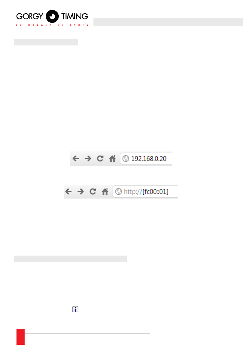
► To access the WEB site, type-in the address of the device in the address eld of your
WEB browser (as shown below) and validate the input.
► To access the server via its IPv6 address, you have to type it between brackets
► It is better to always use the most up to date web browser versions, in order not to
experience display compatibility issues
5.2. WEB INTERFACE DESCRIPTION
5.2.1. Navigation menu
The index page appears when accessing the WEB interface of the LEDI® Network TDS
V1.
Each time this icon : is shown, the user can hover it with the mouse to get additional
information about the concerned eld.
20
MDE-LEDI-NETWORK-TDS-4099V1.0
Page 21
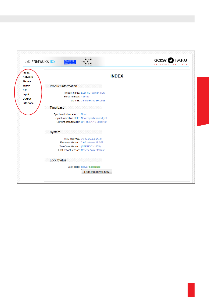
On the left, a menu allows switching between the different pages of the web interface
.
ENGLISH
1. Index: general information about the product.
2. Network: Settings of network parameters.
3. Alarms: Conguration of the static relays.
4. SNMP: Conguration of the SNMP module.
5. NTP: Diagnostic and conguration of the NTP Server/Client.
6. Input: Input time code, autonomy and autonomous running mode conguration.
7. Output: diagnostic and conguration of output cards.
8. Interface: Settings for the web pages and the other server interfaces.
☛ Except the index page, all the pages’ accesses are restricted.
The default login is: Username : root Password : gtmt
MDE-LEDI-NETWORK-TDS-4099V1.0
21
Page 22
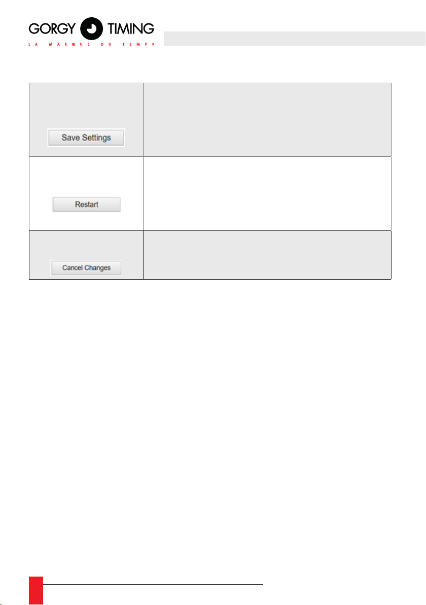
► One or several of the following buttons can be found on each Web page:
Saves the changes in ash memory instead of temporary
memory. Therefore the information is saved even in case of
« Save Settings »1 button
power interruption.
Some parameters require the device to be restarted in
order to be applicable.
Restarts the time server’s software.
« Restart »1 button
Only the accessed Ethernet interface is restarting.
The “Restart” button is available on Web pages with para-
meters requiring the server to be restarted when modied..
« Cancel Changes »
button
Cancels any non-recorded modication.
Has the same effect as refreshing the Web page (“F5”
hotkey in most Internet browsers).
1
- Notes about the use of the “Save Settings” and “Restart” buttons:
► A partir du micrologiciel NTPServ 2.00 release 17.292 inclus:
The “Restart” button is available on Web pages with parameters requiring the server
to be restarted when modied.
After clicking on “Save Settings”, the message “Warning! A reboot is required to
apply some changes saved.” appears above the “Save Settings” button.
The user may carry on with the changes on different Web pages and restart the server once all the parameters are set up, or choose to restart the server immediately
after by clicking the “Restart” button. The time outputs are then interrupted for a few
seconds to give time to the server to reboot.
22
MDE-LEDI-NETWORK-TDS-4099V1.0
Page 23
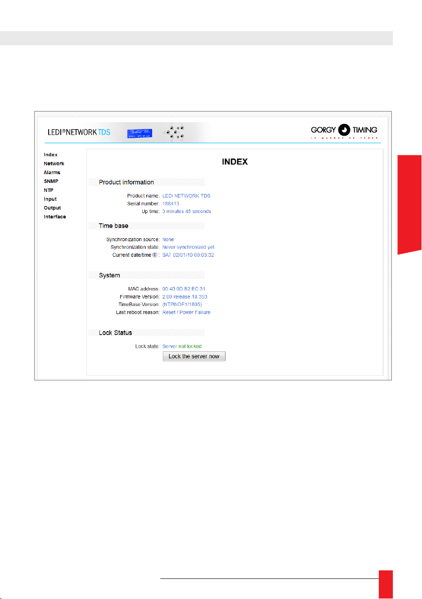
5.2.2. "Index" page
Clicking the Index button displays general product information.
ENGLISH
Product Information
► Product name ► lDisplays the name of the server: LEDI® NETWORK TDS V1
► Serial number ► Displays the GORGY TIMING serial number of the product. This
is a 6 digits number which is the same than the one stamped on the bottom or background of the rack.
► Up Time ► total time during which the LEDI® NETWORK TDS V1 has been running
since the last reset or general power failure.
Time Base
► Synchronisation source ► The current input used for synchronization: “NTP” or
“DCF Radio Code”
► Synchronization state ► The state of the input designated in the previous line
► Current date/time ► The time currently delivered by the server, in UTC format. (+0
time zone, no DST (Daylight Saving Time) policy)
MDE-LEDI-NETWORK-TDS-4099V1.0
23
Page 24
System
► MAC Address ►
The Medium Access address of the Ethernet interface of the device.
► Firmware version ► The current version of the embedded software. The rst two
digits correspond to the year, the other three digits correspond to the day of the
release date of the rmware.
► Time base version ► the number of the microsoftware managing the time base.
That number is “NTPINDF1/1805” for the products setup for GPS or DCF synchronization and “NTP Client” for the products setup for NTP input.
► Last reboot reason ► Indicates why the device has restarted the last time.
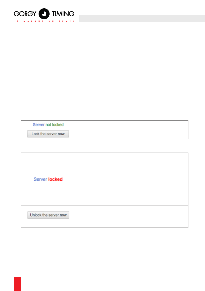
Lock Status
The “Lock Status” section displays information and setting options about the server’s
lock status.
► Serveur déverrouillé :
Normal operating status
Pressing the button will switch to “Server locked” status.
► Serveur verrouillé :
Degraded status.
The server detected a time gap superior to the authorized threshold on its synchronizing input, or the status
was forced by pressing the button “Lock the server now”.
Under this status, the server no longer delivers synchronization time output codes..
Pressing the button will switch to “Server not locked”.
The “Server not locked” status is also the default status
after rebooting.
24
MDE-LEDI-NETWORK-TDS-4099V1.0
Page 25
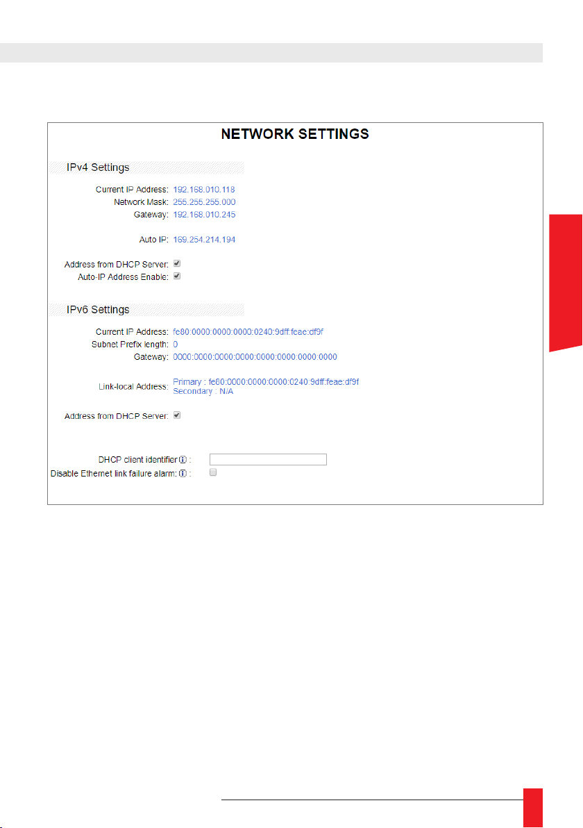
5.2.3. "Network" page
ENGLISH
MDE-LEDI-NETWORK-TDS-4099V1.0
25
Page 26
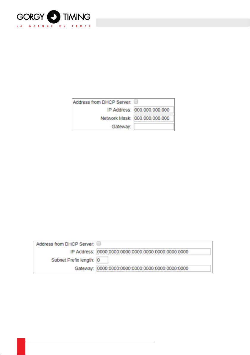
IPv4 Settings
The current IPv4 parameters are displayed.
► Address from DHCP server
If the box is checked, the LEDI® NETWORK TDS V1 attempts to get an IPv4 address from a DHCP server on startup. Failing to obtain an address this way will
result in the server using its automatically congured IPv4 address.
Unchecking the previous checkbox gives access to the following settings:
► IP Address
Sets up the IPv4 address of the LEDI® NETWORK TDS V1 on the network under
the following format: xxx.xxx.xxx.xxx, where “xxx” are numbers from 0 to 255.
► Network submask
Sets up the mask of the sub-network to be used. For example, 255.255.255.0 indicates that the scope ranges from 192.168.0.1 to 192.168.0.254.
► Gateway address
The gateway address must be determined for the LEDI® Network TDS V1 to be able
to communicate with elements of the submask. Otherwise leave a blank eld.
► Auto-IP Adress Enable
If the box is checked, an Auto-IP address (i.e. 169.254.x.x/16) is attributed to the
server in addition to the manual or DHCP address. This is a default setting.
IPv6 Settings
The current IPv6 parameters are displayed.
► Address from DHCP server
If the box is checked, the LEDI® Network TDS V1 attempts to get an IPv6 address
from a DHCP server on startup. Failing to obtain an address this way will result in
the server using its automatically congured IPv6 address.
26
MDE-LEDI-NETWORK-TDS-4099V1.0
Page 27
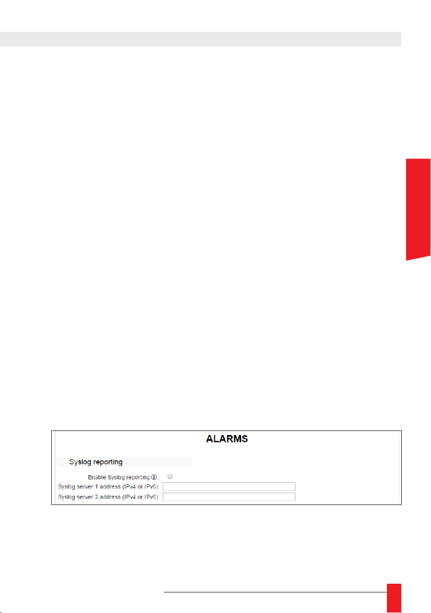
Unchecking the previous box gives access to the following settings:
► IP Address
Sets up the IPv6 address of the LEDI® Network TDS V1 on the network either
in a reduced format (i.e. fc00::0001 in the example above) or in a complete format
(i.e. fc00::0000:0000:0000:0000:0000:0000:0001)
► Prex length
Sets up the length of the submask prex. For example, a length of 64 indicates that
(fec0:0000:0000:0000: in the example above) denes the network.
► Gateway address
The gateway IPv6 address must be determined for the LEDI® Network TDS
V1 to be able to communicate with elements of the submask can be either
in a reduced form (i.e. fc00::0008 in the example above) or in a full form
(i.e. fc00::0000:0000:0000:0000:0000:0000:0008). Otherwise leave the default value at
(0000:0000:0000:0000:0000:0000:0000:0000)
The last part of the page enables the conguration of the following parameters:
► DHCP client identier :
Set the DHCP identier in a string which will be sent as option #61 when the DHCP
request is done.
► Disable Ethernet link failure alarm :
Checking this box will prevent the front screen from displaying an alarm when the
Ethernet management port is unplugged.
5.2.4. "Alarms" page
Use this webpage to congure all the alarms the LEDI® NETWORK TDS V1 server can
report by email.
ENGLISH
Syslog reporting
► Enables the LEDI® Network TDS V1 to send Syslog messages
NOTE: It is recommended to use SNMP supervision instead of Syslog reporting (see section "5.2.5. SNMP page").
☛ Syslog messages are described in “8. Appendix C- Maintenance” of the
user manual.
MDE-LEDI-NETWORK-TDS-4099V1.0
27
Page 28
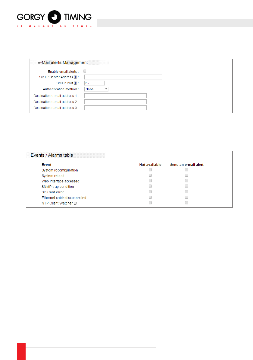
E-Mail alerts Management
► Use this page to set up the parameters for sending email as well as sending conditions.
► The “SMTP Server Address” eld can be lled with an IP address or a host name.
► The SMTP server in use must be set up as to accept SSL unsecured connections.
► The following table enables the user to determine which event will trigger an email
expedition
.
28
MDE-LEDI-NETWORK-TDS-4099V1.0
Page 29
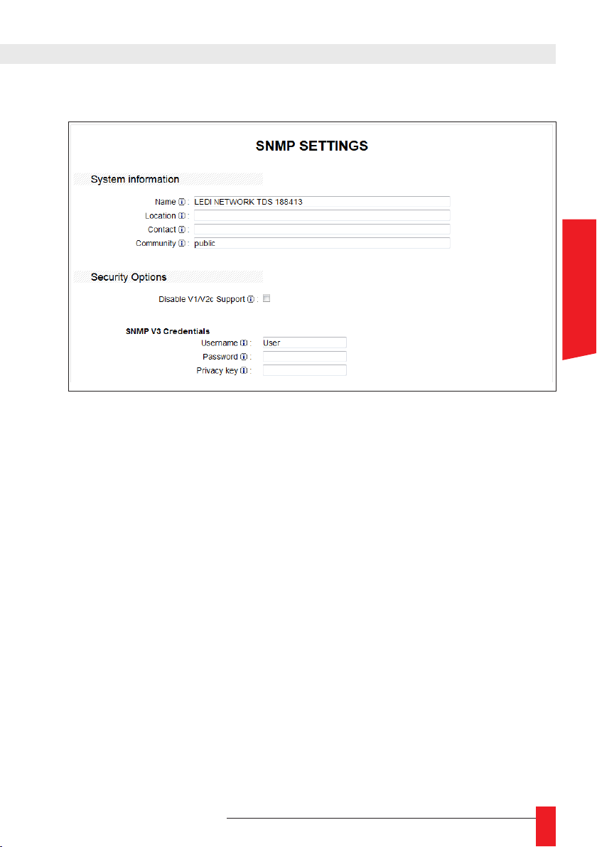
5.2.5. "SNMP" page
Use this section to set up the supervision SNMP agent running on the LEDI® NETWORK
TDS V1.
System information
► The three elds “Name”, “Location” and “Contact” can be freely lled to provide
information about the LEDI® NETWORK TDS V1
► The community eld is used for the SNMP v1 & v2c versions. The request sender’s
community must match the content of the eld in order for the request to be processed.
ENGLISH
Security options & SNMPv3 credentials
► The LEDI® NETWORK TDS V1 implements a fully compatible SNMPv3 server, with
security options.
► The server can deactivate versions 1 and 2c of the SNMP protocol so that it doesn’t
answer unsecured requests
► To use the security features of the SNMPv3 protocol, specify a username, a
password and an encryption key in the corresponding elds.
► Filling the Password eld automatically enables the password verication on inco-
ming SNMPv3 requests. Filling the Privacy key eld automatically enables encryp-
tion on SNMPv3 exchanges.
► If both elds are lled, the server only answers requests with valid passwords and
privacy keys.
MDE-LEDI-NETWORK-TDS-4099V1.0
29
Page 30
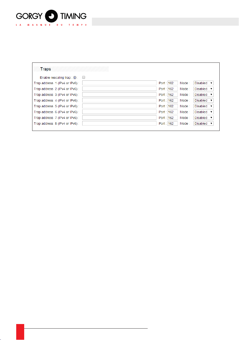
Traps
► SNMP traps are alarm messages sent by the LEDI® NETWORK TDS V1 in different
situations.
► Please refer to the MIB for more information about the SNMP traps messages of the
LEDI® NETWORK TDS V1.
► Up to 8 IPv4 addresses can be congured on different slots with different SNMP
versions.
☛ Any modication of the “Username,” “Password” and “Privacy key”
elds requires the network interface to be rebooted in order to be
applicable.
30
MDE-LEDI-NETWORK-TDS-4099V1.0
Page 31
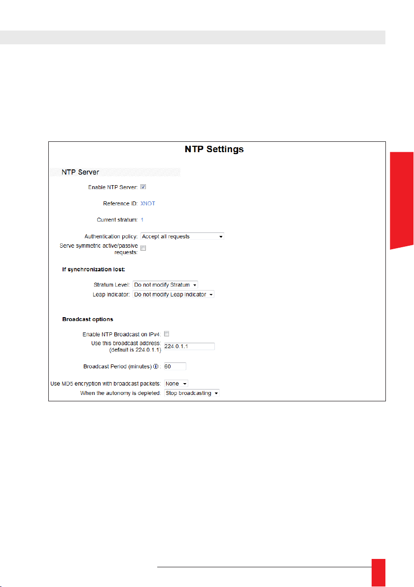
5.2.6. "NTP" page
The NTP conguration panel indicates the synchronization mode used by the server or
selected by the NTP software, as well as the servers dened by the user.
NTP Server section
Use this part to setup parameters for the NTP server
ENGLISH
Enable NTP Server
► If this check box is not checked, the server will not answer to any NTP request.
Reference ID
► This eld shows the current “Reference Identier” used in NTP messages. It is auto-
matically computed depending on the LEDI® NETWORK TDS V1 synchronization
status. It can be “DCF” (DCF or GPS synchronization), XNOT if the product is not
synchronized, or correspond to the IP address of an NTP server (NTP synchronization).
Current stratum
► The stratum value to be stored in the NTP messages sent to the NTP clients.
MDE-LEDI-NETWORK-TDS-4099V1.0
31
Page 32

Authentication policy
► Use this eld to choose whether the server will answer to a NTP request, based
on presence of a security MD5 hash. The server can be congured to accept any
request, only secured requests or only unsecured requests.
Serve symmetric active/passive requests
► Checking this box will enable NTP symmetric active/passive requests mode.
If synchronization is lost
► Use this part to determine the behavior of certain elds of the NTP answer message
when synchronization is lost.
► Stratum Level
Stratum level can be modied.
Values can be set from 1 to 16. Select the “Do not modify Leap Indicator” option
to keep the value for the LI eld when synchronization is lost.
► Leap Indicator
The stratum level sent can be modied.
Available values are “3 (0b11)” or “Do not modify leap indicator” to avoid mo-
difying the L1 eld when synchronization is lost.
Broadcast options
The user can ask the LEDI® NETWORK TDS V1 to broadcast time on any address of
the subnetwork by specifying the broadcast address. Also works with a multicast or
unicast address.
☛ This mode allows to synchronize a high number of clocks rapidly.
Enable NTP broadcast on IPv4
► Check this box to set up separate broadcast modes on IPv4.
“Use this broadcast address” elds
► Fill in these elds to enter the IP addresses to be used in broadcast mode.
Broadcast period
► Sets the periodicity of NTP broadcast time messages sent to the specied IP ad-
dresses.
32
MDE-LEDI-NETWORK-TDS-4099V1.0
Page 33
Use MD5 encryption
► Activates the MD5 hash on NTP broadcast messages.
► Select the key in the menu (“Key #1” to “Key #8”) and ll in the corresponding eld
in the “MD5 Keys” area to activate MD5 hashes.
When the autonomy is depleted
► Use this box to choose whether the server keep broadcasting the time in case of
loss of synchronization autonomy.
Section "NTP Client"
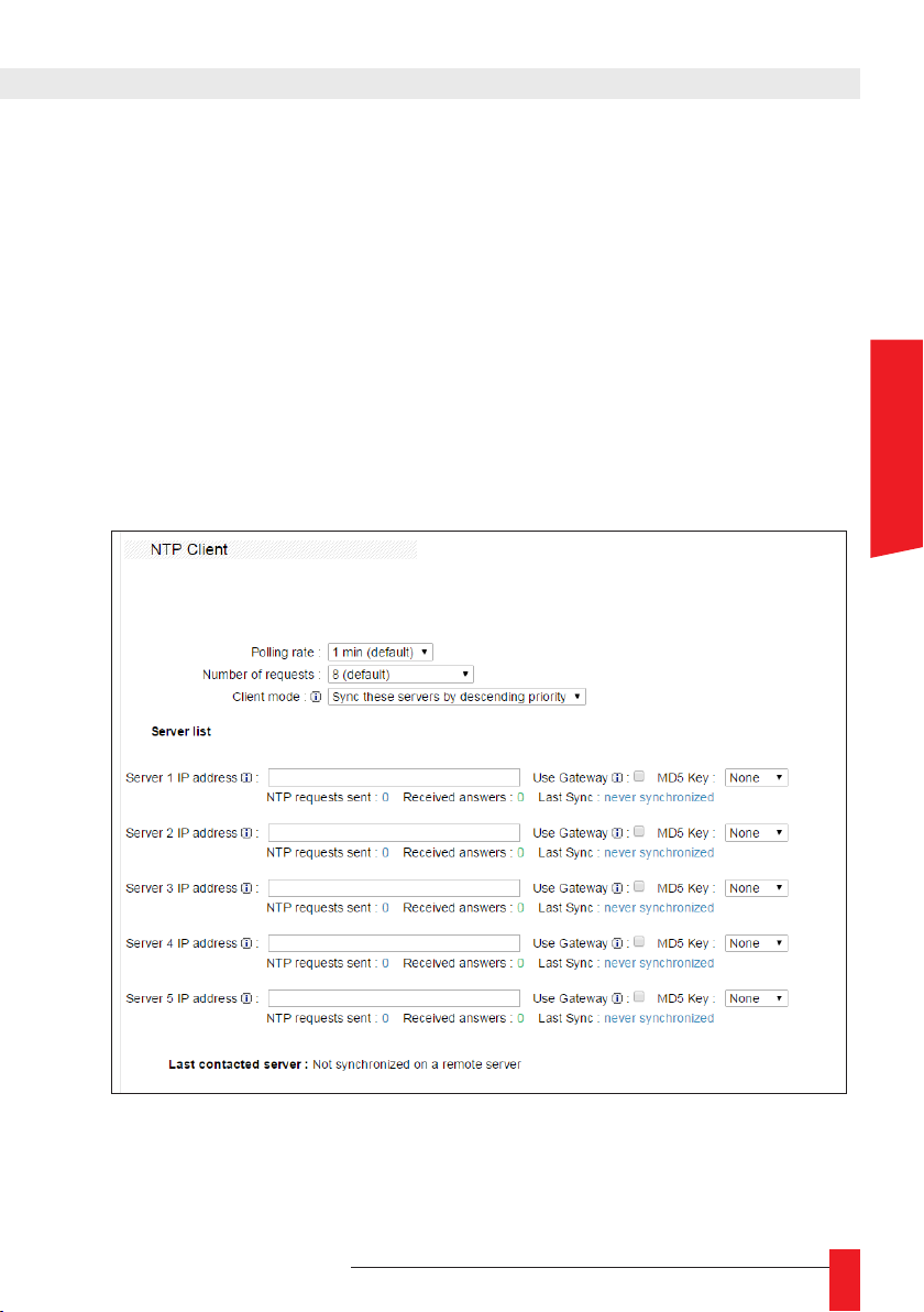
If available, the LEDI® NETWORK TDS V1 can be synchronized on up to 5 NTP servers. The NTP software actually uses only one server at a time but can switch to ano-
ther server when there is no or insufcient reply.
ENGLISH
MDE-LEDI-NETWORK-TDS-4099V1.0
33
Page 34
Polling rate
► This list denes how often the NTP servers will be polled for synchronization.
Number of requests
► This list congures the number of NTP messages to be sent in a train of requests at
the requested polling rate.
Client mode
► The NTP client sends queries to all servers one by one according to their position in
the list. Therefore, the NTP client rst sends a query to the server at the top of the
list on startup. If the rst server isn’t available or if no NTP address is provided, the
NTP client sends a query to the second server and so on.
The “Client mode” denes the way the NTP client switches from one server to another under normal operating conditions in the case of loss and return of the servers
availability (hardware failure, network failure, etc.).
The NTP client only switches servers if the current server is unavailable.
For example:
- The NTP client is synchronized on server 1.
Sync these servers by
descending priority
Sync highest available
server in the list
- An incident on server 1 makes it unavailable.
- The NTP client therefore synchronizes on server 2.
- Server 1 becomes available again.
- The NTP client remains synchronized on server 2.
Note: in this mode, the number of NTP queries is minimized..
The NTP client attempts to synchronize with the higher server on the list.
For example:
- The NTP client is synchronized on server 1.
- An incident on server 1 makes it unavailable.
- The NTP client therefore synchronizes on server 2.
- The NTP client keeps querying to determine when server 1 becomes
available again.
- Server 1 becomes available again.
- The NTP client switches back on server 1 and stops sending queries
to server 2.
Note: in this mode, the NTP client keeps querying server(s) located
higher on the list than the server it is synchronized with.
34
MDE-LEDI-NETWORK-TDS-4099V1.0
Page 35
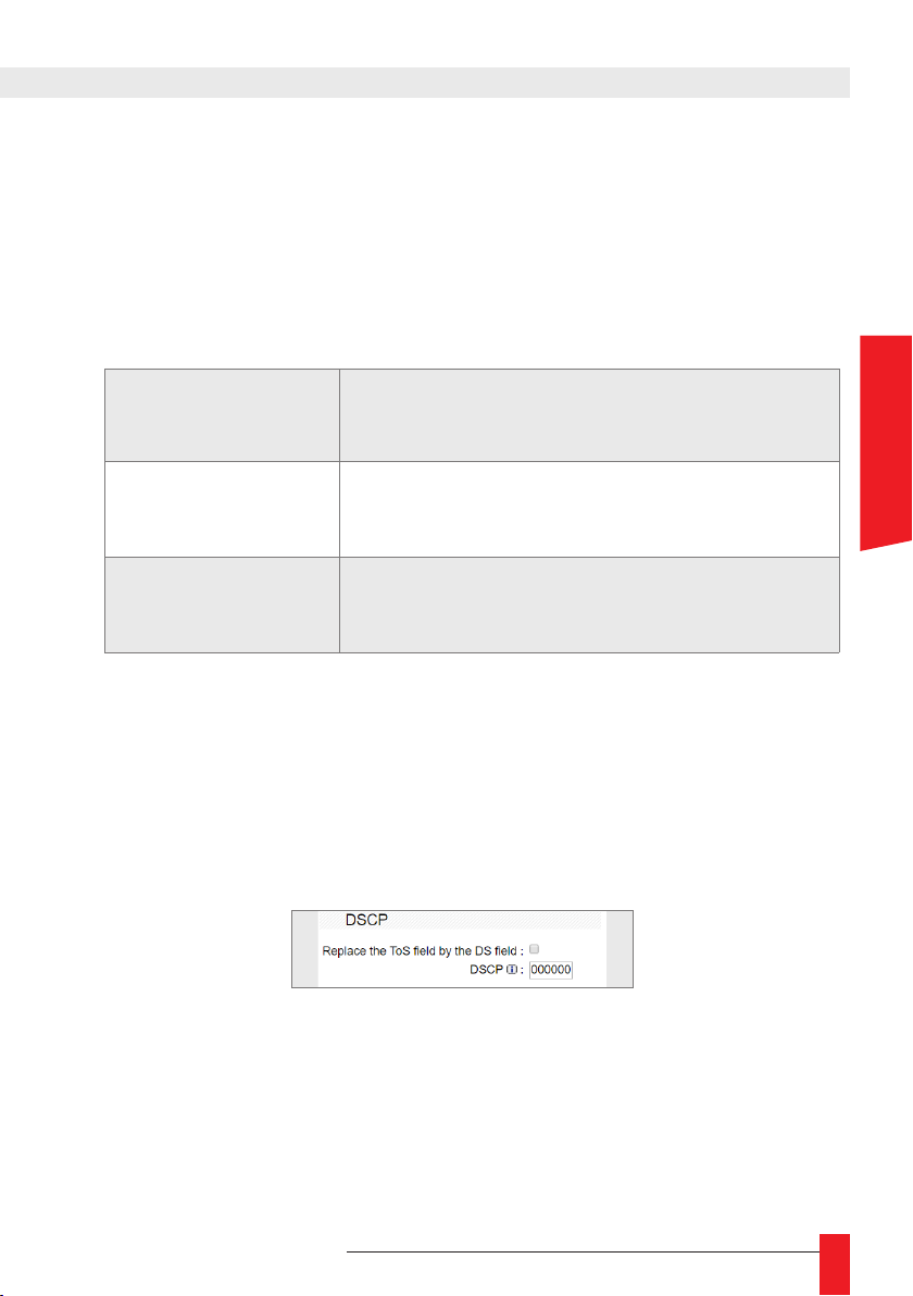
Server list
Use these elds to enter NTP servers IPv4 addresses manually.
The “Use gateway” box must be checked if the contacted server is outside the local
network.
If the index of an MD5 key is provided, the LEDI® NETWORK TDS V1 adds corresponding MD5 hashes to NTP messages when querying the servers.
Statistics on servers availability are also available:
NTP requests sent
Received answers
Last Sync
Number of queries sent by the server since the NTP
client was activated.
Number of answers received by the server from the
contacted NTP server.
Data about the period during which the embedded NTP
client correctly contacted the distant server.
Last contacted server
► This elds indicates the server currently used as a synchronization source.
Section "DSCP"
Use this to activate the Differentiated Service Code Point (DSCP). When activated, the
ToS eld form the title of IPv4 packages is replaced by the DSCP eld. Please see RFC
2474 for more information.
ENGLISH
MDE-LEDI-NETWORK-TDS-4099V1.0
35
Page 36
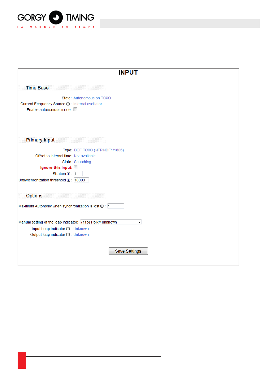
5.2.7. "Input" page
The input page regroups information and settings about the time input available on the
LEDI® NETWORK TDS V1.
Time Base
State
► This eld provides information about the type of oscillator of the time base.
Current Frequency Source
► This eld indicates the clock signal used by the LEDI® NETWORK TDS V1. It will
always display "Internal Oscillator".
36
MDE-LEDI-NETWORK-TDS-4099V1.0
Page 37
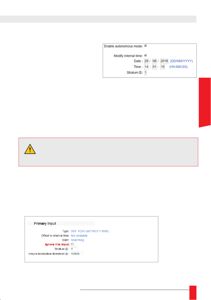
Enable autonomous mode
► Checking this box will cause the
LEDI® NETWORK TDS V1 to
switch to ‘Free Running” mode
where it will run autonomously without a synchronization source.
When the box is checked, the following options become available:
► Modify internal time
Checking this box allows to modify and impose the intern time on the system
when it is in “Free Running” mode. Intern time and date will be displayed UTC.
For example, if local French time is 20:59:00 on 01/02/2010, enter 19:59:00 on
01/02/2010 (one hour earlier since France is UTC+1, DST OFF at this time of
the year).
► Stratum
Stratum default value can be imposed in “Free Running” mode.
The stratum default value is 1.
WARNING: Free Running mode should only be used for test
purposes. Time may be inaccurate since it may depend on the
user’s settings.
Primary Input
Several options are available depending on the synchronization input type.
The images below show the available information according to the synchronization input
type.
ENGLISH
DCF input version
MDE-LEDI-NETWORK-TDS-4099V1.0
37
Page 38
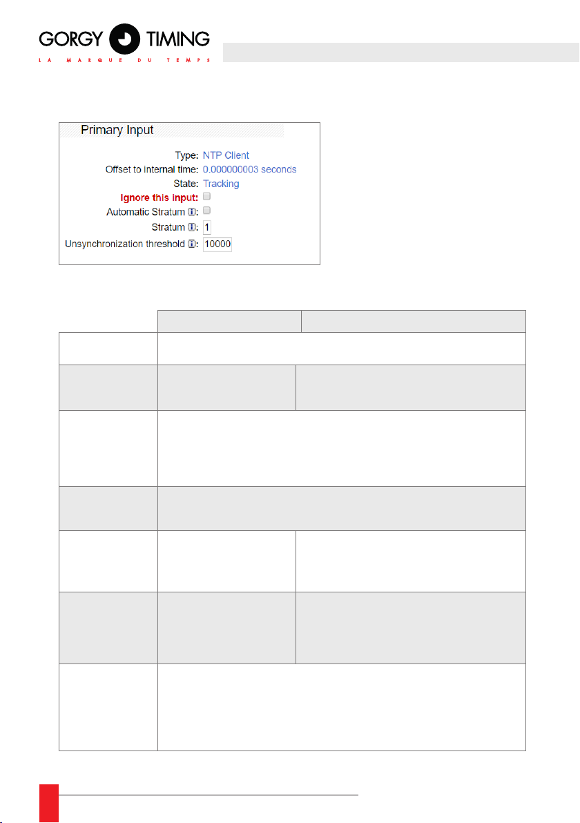
NTP client input version
Description and available parameters
► The table below details the available features for each synchronization input type
DCF/GPS NTP
Type
Offset to
internal time
State
Ignore
this input
Automatic
stratum
Stratum
Unsynchronization
threshold
Series of xed characters including the synchronization type (DCF or NTP).
Not available
IIndicates the general status of the synchronization source and the date of the latest
change in status.
• Ignored ([difference]) ► time input is ignored after a leap
• Selectable ► time input is ready to synchronize with the time server
• Not selectable ► time input is not ready to synchronize with the time server
• Error ► time input is failing
Checking this box has the server ignoring the synchronization input. The server
therefore goes in alarm mode and displays “NO TIME CODE” on the LCD screen.
Not available
Use this eld to manually set
up the stratum value of the
NTP server (from 1 to 16).
Use this eld to prevent any sudden leaps. The detection threshold can be set up
between 20µs and 499000µs with 1µs minimal increase.
Setting the value to “0” deactivates the protection against time leaps.
Reports the difference between the internal clock
and the NTP server
Activates the automatic set up of the stratum value.
When activated, the stratum value is calculated
based on the stratum value received in the NTP
packages.
Use this eld to manually set up the stratum value
of the NTP server (from 1 to 16).
That eld is hidden when the “Automatic Stratum”
option is activated
38
MDE-LEDI-NETWORK-TDS-4099V1.0
Page 39

Options
Maximum autonomy when synchronization is lost
► When the time source is lost, the device works in autonomous mode. When the auto-
nomy time end is reached, the device’s outputs and NTP server stop providing time.
The autonomous running duration can be set or deactivated here (void or “disabled”
setting).
Manual setting of the leap indicator
► Use this option to manually assign the leap indicator.
► If the server runs autonomously or is in “Free Running” mode when the date changes
to January 1st or June 1
st
and that option denes a second leap, the correction ap-
plies automatically on the time base.
► “Input Leap Indicator” and “Output Leap Indicator” allow to visualize the status of the
time leap eld received at input and sent at output.
ENGLISH
MDE-LEDI-NETWORK-TDS-4099V1.0
39
Page 40
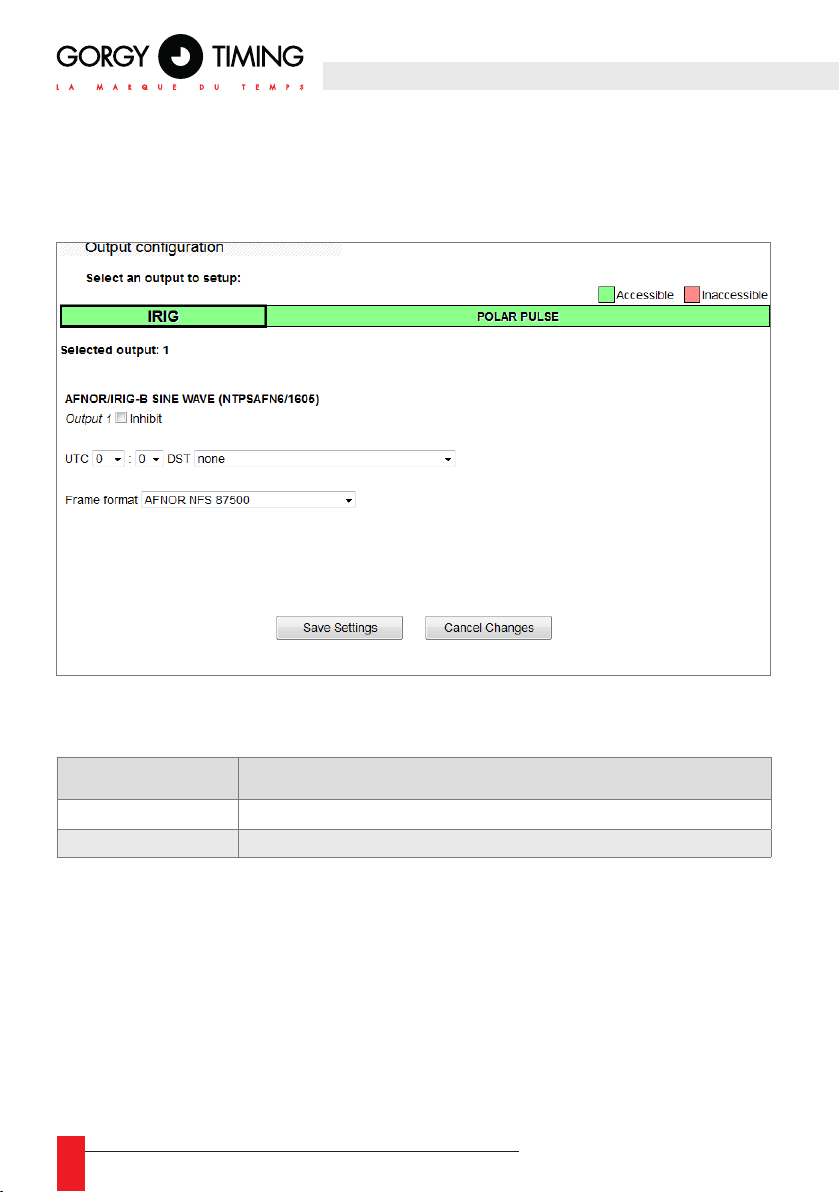
5.2.8. "Output" page
Use this page to nd information about the status and conguration options of all the output
cards in the LEDI® NETWORK TDS V1 and set them up one by one.
The extension cards appear in a table at the top of the page.
► There are two different outputs:
NAME Card Description
IRIG Output 1 x AFNOR NFS 87500/IRIG B (Modulated 1khz)
POLAR PULSE Serial polarized pulse output
► Each detected card has its own setup page that can be accessed by clicking on the
box containing the card’s name
► The selected box is displayed with wider borders.
► The boxes also display the availability of the cards on the internal bus. A green
colored box indicates that the output card communicates properly with the main
card. A red colored box indicates an internal communication issue. In that case, the
parameters are not readable and it is very likely that the card does not provide the
time code on its output.
40
MDE-LEDI-NETWORK-TDS-4099V1.0
Page 41
In case of no internal communication with the output cards, the front screen displays
the message “Output Alarm!”. If the issue persists over time or after rebooting the
device, please contact Gorgy Timing Customers’ Service
Options standard communes
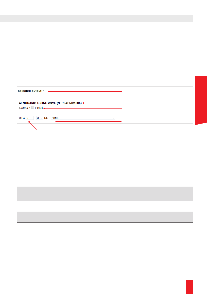
The image below shows the information eld shared by all conguration cards. The conguration page of the cards displays all or part of these elds.
Internal address of the selected card
Description and hardware version of the card
Deactivation of the output
Summer/winter daylight saving time policy
Offset to UTC time (“hh:mm” format)
Selected output
► Sends the card’s address on the internal communication bus. Also corresponds to
the physical location number of the output card.
Type (Nom Prog. / Version)
► This eld sends the description of the extension card type, the name and the version
of the embedded microsoftware . This eld can have the following values:
ENGLISH
Card Type Prog. name Version Note
IRIG
POLAR PULSE
MDE-LEDI-NETWORK-TDS-4099V1.0
AFNOR/IRIG-B
SINE WAVE
POLARISED
PULSES MODULE
NTPSAFN6 1605 Original version
TSPULSEV1 1726 Original version
41
Page 42
Disable the output card
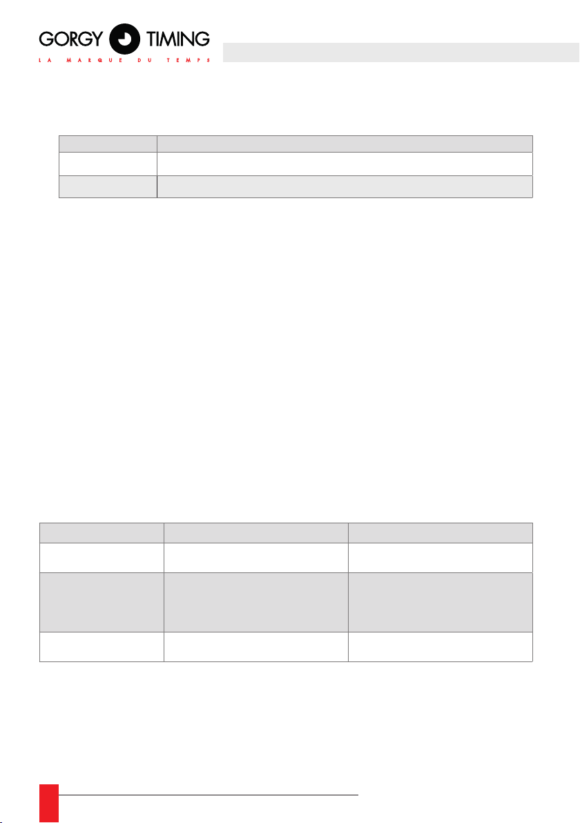
► Disabling the output cards will have the following effects:
Card Effects
IRIG The 1kHz carrier is present but no longer modulated
POLAR PULSE Polarized impulsion generation is stopped
UTC (Fuseau horaire)
► Under normal operating conditions, the internal time of the device is UTC time. In
order to send local time to the outputs, it is necessary to apply a shift from the UTC
time rst. When a DST correction is implemented, there are two “categories” of time
during the year.
► The rst eld allows to select the sign of the shift (negative “-“ or positive “+”) and
the number of hours (between “00” and “12”).
► The second eld allows to select the minutes of the shift (between “00” and “55”).
For example, the time shift for France is “+01:00”.
DST (Daylight Saving Time)
► Besides UTC, some countries implement a summer/winter time correction. This
correction must be congured to get the actual local time. When a summer/winter
time correction is implemented, there are two different categories of time in the year:
- Summer time (UTC +1 hour)
- Winter time (UTC).
► The existing available policies are detailed in the table below:
DST Begins Ends
European Union Last Sunday of March 1Am UTC Last Sunday of October 1Am UTC
USA / Canada / St. Johns
/ Bahamas / Turques /
Caïques
Australie – Standard First Sunday of October 2Am local time First Sunday of April 3Am local time
Second Sunday of march 2Am local time
First Sunday of November 2Am local time
For example: in France, the DST policy is the “European Union” policy
42
MDE-LEDI-NETWORK-TDS-4099V1.0
Page 43
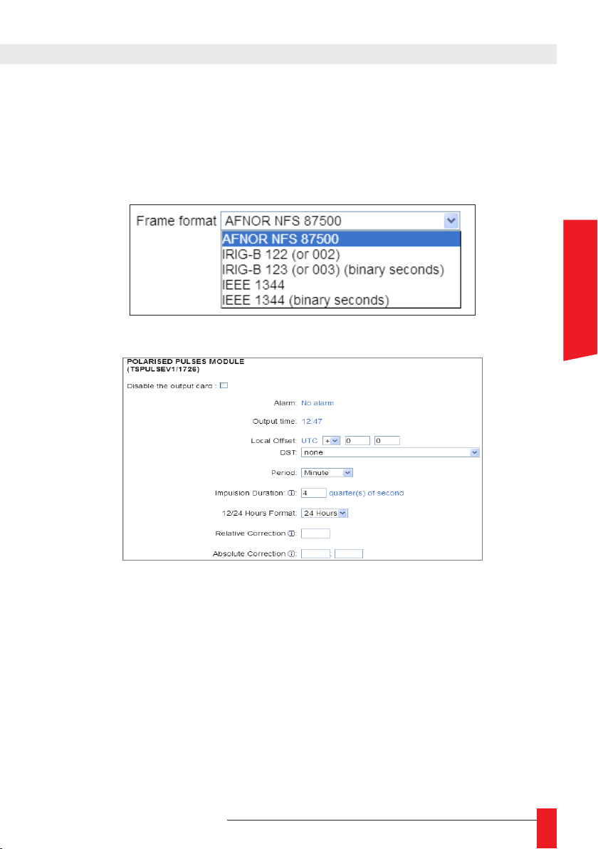
Specic options
Some output cards have specic setup options.
AFNOR/IRIG-B :
► The IRIG frame format can be modied.
POLAR PULSE :
ENGLISH
► Alarm: alarm indicator (power, open serial circuit, parallel short-circuit).
► Output time: displaying the time sent to impulsion clocks.
► Period: impulsion selection every minute or half-minute.
► Impulsion Duration: setup of the impulsion in quarter-seconds.
► 12/24 Hours Format: selection of the time format sent at the standard 0 to 23 hours
(digital clocks) or at the standard 1 to 12 hours (analogic clocks).
► Relative Correction: adds or takes a number of impulsion from 1 to 9 without modifying
the time sent (example of application: polarity settings).
► Absolute Correction:
MDE-LEDI-NETWORK-TDS-4099V1.0
time tuning on impulsion clocks
.
43
Page 44

Starting procedure:
► Tick the box “Disable the output card” and press “Save Settings” to stop the
impulsion generation.
► Connect the clock line to the back slot.
► Set up the offset and the DST policy.
► Set up the period, the impulsion time and the format.
► Write down the hour and minute displayed by the receiving clock.
► Uncheck the box “Disable the output card” and press “Save Settings” to initiate
the fast forward impulsion generation (1 impulsion every 2 seconds) or put it on
hold if the time to retrieve is too long (that time depends on the format and of the
mode used –minute or half-minute). Fast forward (or hold) of impulsion generation will be stopped automatically when the delivered time is identical to the base
time displayed on the front screen after correction of the local time offset if any..
☛ In case of impulsion shift, adjust the polarity by selecting +1 or -1
in the « Relative Correction » eld then press « Save Settings ».
44
MDE-LEDI-NETWORK-TDS-4099V1.0
Page 45
5.2.9. INTERFACE page
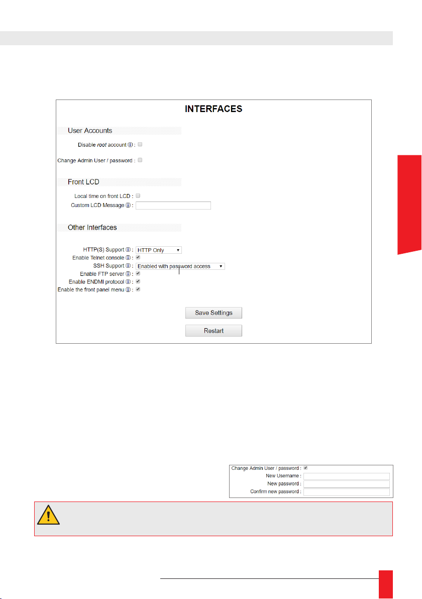
Use this page to set up the different management interfaces of the LEDI® NETWORK TDS V1.
A. User Accounts
ENGLISH
Disable root account
► By default, the LEDI® Network TDS V1 can be accessed via a root account. This
account can be deactivated to ensure maximum security. The only way to access the
server is then the administrator account, dened in the next elds group. If the administrator account password is unknown, the only way to access the server is to revert it
to factory defaults. All the settings will be lost and the root account will be reactivated.
Change admin/user password
► Check this box to modify the credentials
for the administrator account.
The default administrator account credentials are:
Username: admin Password: password
MDE-LEDI-NETWORK-TDS-4099V1.0
45
Page 46
B. Front LCD
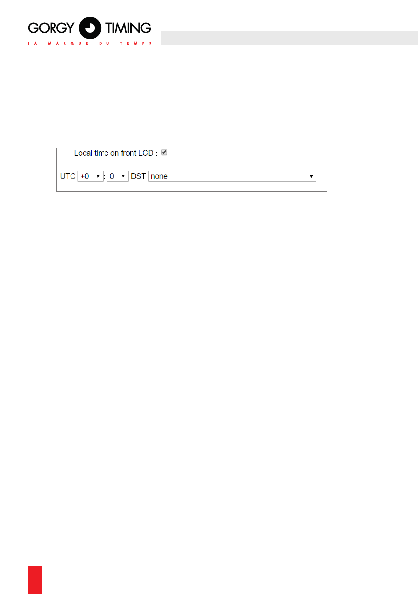
Local time on front LCD
Checking this box displays the local time on the LCD front screen with the mention
“(LOC)”. Otherwise, UTC time is displayed with the mention “(UTC)”.
Check the time zone and DST boxes to congure them.
Custom LCD message
► Filling this eld displays a message on the third line of the LCD screen. If alert mes-
sages also have to be displayed by the device, these would appear on the third line
alternatively with the custom message.
C. Other interfaces
HTTP(S) support
► Use this page to restrict access to the webpage to HTTP or HTTPS requests only or
to allow both. HTTPS connections are more secured but consume more resources.
Loading is then slower.
The user can provide his/her own security certicates via several methods:
1. In the Start menu, enter “cmd” in the search eld then launch cmd.exe
2. Enter the command cd<emplacement>, where <emplacement> is the path to
the folder containing the ssl.cert and ssl.key les
3. Enter the command ftp <address>, where <address> is the IP address of the
module onto which you want to install the certicates
4. Enter login (by default: root)
5. Enter password (by default: gtmt)
6. Enter the command cd .cfg
46
MDE-LEDI-NETWORK-TDS-4099V1.0
Page 47
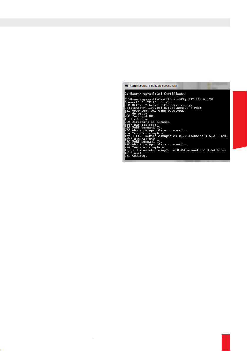
7. Enter the command put ssl.cert
8. Enter the command put ssl.key
9. Enter the command quit
The picture below shows the mes-
sages displayed. Here, the certicate les are in C:\Users\xgerault\
Certicats and the IP address of
the module is 192.168.0.128.
Enable Telnet console et Enable SSH console
► NTPServ command invite
The time servers LEDI® NETWORK TDS V1, LEDI® NETWORK ITSv2, LEDI®
NETWORK ATS and their NTP output cards as well as the NT0825, NT023 and
NT022 modules of the RT4000 feature a command prompt reachable by Telnet
(port 9999) and by SSH (port 22). These commands enable to read the servers
status and parameters and to congure them.
Contrary to the Telnet protocol, the SSH protocol includes authentication and data condentiality by cryptography.
For more information on the Telnet and SSH protocols see,
https://fr.wikipedia.org/wiki/Telnet and https://fr.wikipedia.org/wiki/Secure_Shell.
ENGLISH
► Command prompt access
The command prompt may be opened by several applications, e.g. ssh, Putty and
Teraterm. Username and password are required to access the product. These are
either root/gtmt if the root account has not been disabled or the congurable user
account identiers (admin/password by default).
It is also possible to connect with a public key. This key and its private key may be
generated with the “ssh-keygen” command under Linux or Cygwin in “$HOME/.ssh/
id_rsa.pub” (public key) and “$HOME/.ssh/id_rsa” (private key), then simply add the
le "authorized_keys" in the folder ".ssh" by ftp with the content of id_rsa.pub (only
1 RSA 2048 key is supported by the server).
MDE-LEDI-NETWORK-TDS-4099V1.0
47
Page 48
To reduce network attacks risks, SSH clients memorize SSH servers. On the rst
connection to a server or during a computer attack by stealing the server identity, a
warning message should appear. The choice is then given to the user to access to
server or not and to let the SSH client memorize it or not.
► Under Windows
Windows provides the application telnet.exe. To connect to a Gorgy Timing
product:
1. Launch “cmd.exe“
2. Enter “telnet <IP> 9999” where <IP> is the IP address.
Windows does not feature an application for the SSH protocol. A client
software like Putty or Teraterm must therefore be installed.
If asked by these applications, the SSH connection parameters are:
- SSH version 2 (ou SSH2)
- Port TCP 22
► Under Linux
1. Launch a terminal
2. Enter ssh -c aes128-cbc -m hmac-md5 <login>@<IP>
where: <login> is the administrator username
<IP> is the product’s IP address.
3. If the "Agent admitted failure to sign using the key." error appears when
authenticating with a key, execute:
eval "$(ssh-agent -s)" && rm ~/.ssh/known_hosts && ssh-add
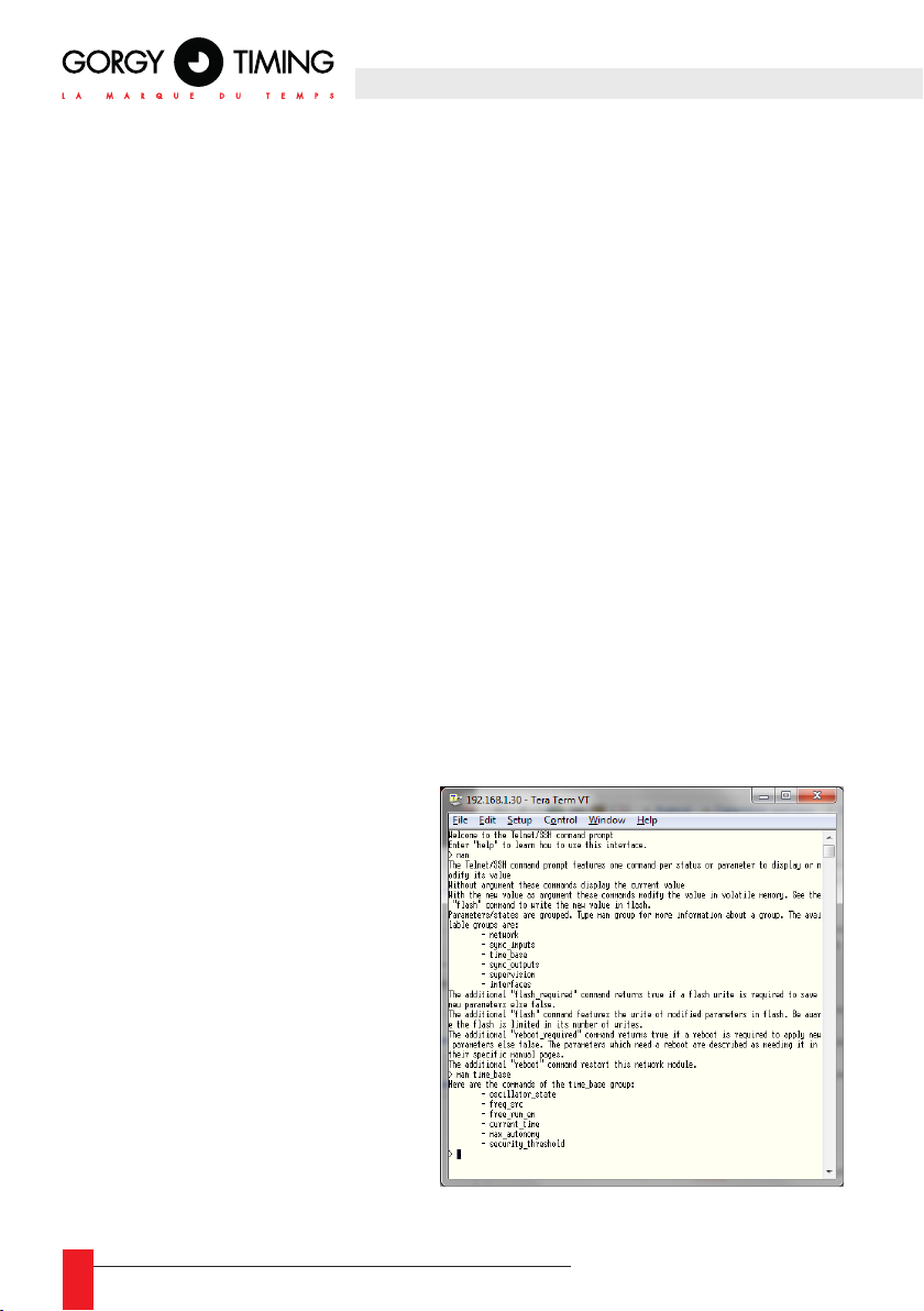
► Use of the command prompt integrated manual
The manual can be displayed
via the “help” and “man” commands. These 2 commands
have the same effects:
► If no argument is given,
they display the main
page of the manual.
► If a page name is given as
argument, they display the
corresponding page of the
manual.
There are 2 types of manual pages:
► A command help (one
page per command)
► The list of pages available
for a feature (one page per
list)
48
MDE-LEDI-NETWORK-TDS-4099V1.0
Page 49

► Use of the status commands
The status commands display the state of an element of the time server. Some
commands use arguments to specify their functioning. For instance, to know if
the NTP input is enabled:
> sync_input ntp en
true
► Use of the conguration commands
Most of the conguration commands can be used as status commands to display the current value of a parameter.
To change a parameter, the new value must be given in argument at the end of
the command. For instance, to disable the NTP input:
sync_input ntp en false
Enable FTP Server
► SIf the feature is enabled, the NTPServ rmware can be updated by uploading an image.
bin le via FTP. To get the latest version of the NTPServ rmware, please contact Gorgy
Timing Customer’s Service.
Enable ENDMI Protocol
► If enabled, the Gorgy Timing discovery protocol will be activated on the LEDI®
NETWORK TDS V1. The device will therefore be detectable by GTNetworkManager2.
Enable the front panel menu
► If enabled, the front panel menu will be accessible by pressing the “OK” button (see
section 4.4 “IPv4/IPv6 conguration).
ENGLISH
► ► If disabled, pressing the OK button will have no effect. Users will no longer have
access to the main menu and won’t be able to change IPv4/IPv6 parameters via this
menu. These changes will only be available via the Web server. A lock icon appear
on the top right corner of the screen.
FRI 20/07/2018 •
20:59:46 (LOC)
SYNC: IRIG
MDE-LEDI-NETWORK-TDS-4099V1.0
49
Page 50
D. Restart button
The device can be remotely rebooted using the Restart button at the bottom of the
page. Then, the web page will not be accessible for approximately 1 min. until the unit
restarts.
5.2.10. UPDATE page
☛ WARNING: Depending on the update, the product may reset all settings
to factory default after updating the rmware. IP conguration will therefore
revert back to DHCP.
For each network port of the server, please follow the NETWORK MODULE UPDATE
PROCEDURE below.
Note: It is possible to launch the update of all modules at the same time to save up some
time (either automatically or by making use of the delay time).
Please read the “WARNINGS” note carefully.
► Updating the rmware via File Transfer Protocol (FTP)
This method is usually used to solve issues or when the web interface is unavailable.
The FTP interface must be activated in the device’s settings.
1 - Open a terminal (Start menu -> Execute -> "cmd")
2 - In the terminal, switch with the "image.bin" le to be sent to the product
using the "cd <emplacement>" command
3- Typey "ftp <IP module address>", ENTER
Login: “root”
Password: “gtmt”
4 - Type:
"bin", ENTER
"put image.bin", ENTER
"quit", ENTER
50
MDE-LEDI-NETWORK-TDS-4099V1.0
Page 51
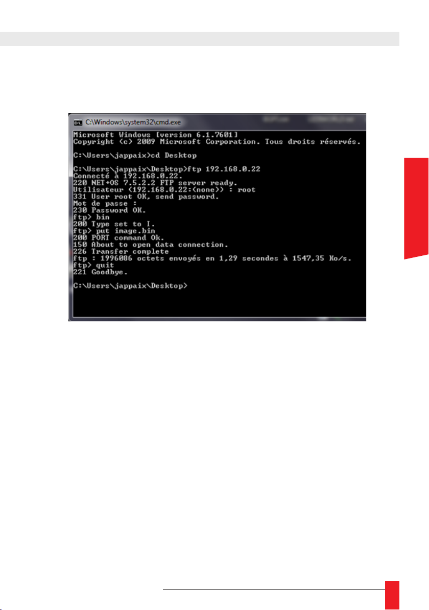
The picture below shows an example of the observed command lines. Here, the
rmware is on the Desktop (C:\Users\jappaix\Desktop) and the module IP address
is 192.168.0.22.
5 - Wait for the module to reboot, do not turn it off before rebooting is complete.
6 - In the terminal, use the “cd” command to switch les with the one containing
the rmware (the approximately 2Mo “image.bin” le) to be sent to the product.
ENGLISH
7 - Type “ftp <IP module address>”, ENTER
Login: “root”
Password: “password”
If the password is denied:
- Type “quit”
- Restart step 7 using “gtmt” as password
8 - Type:
"bin", ENTER
"put image.bin", ENTER
"quit", ENTER
9 - Do not turn off the module before rebooting is complete
Please read the “WARNINGS” note carefully
MDE-LEDI-NETWORK-TDS-4099V1.0
51
Page 52

► Updating via the SSH interface
For this procedure, the SSH interface must be activated in the device’s settings.
1- Open a terminal (Start menu -> Execute ->"cmd")
2- Type "pscp <rmware paht> root@<module IP address>:/", ENTER
If pscp is unavailable, please install the Putty package from the
https://www.chiark.greenend.org.uk/~sgtatham/putty/latest.html
web page then restart step 2
Password: "gtmt"
3- Do not turn off the module before rebooting is complete.
Please read the “WARNINGS” note carefully
☛ WARNINGS
More specically, do not interrupt the product’s functioning or reboot it during
the updating process. The device will reboot on its own when required.
Please also make sure to secure the power source(s) before and during the
update.
The product can be used again when the Web pages can be loaded again in the
browser and the Up Time information displayed in the Index page is superior to
1 minute.
During the update, the product will reboot once or twice. The reboots trigger the
reset of the Up Time. Therefore the value displayed in the Index page must be
coherent with that information.
When in doubt, please wait 5 minutes before rebooting the product. That
duration corresponds to the approximate time needed for two secured reboots
of the product following an update.
Ignoring the recommendations above may result in corrupting the network
cards (NTP output cards or main/management Ethernet port). The related
repairs will be billed and are not covered by the warranty
.
52
MDE-LEDI-NETWORK-TDS-4099V1.0
Page 53
5.2.11. “Diagnostics” page
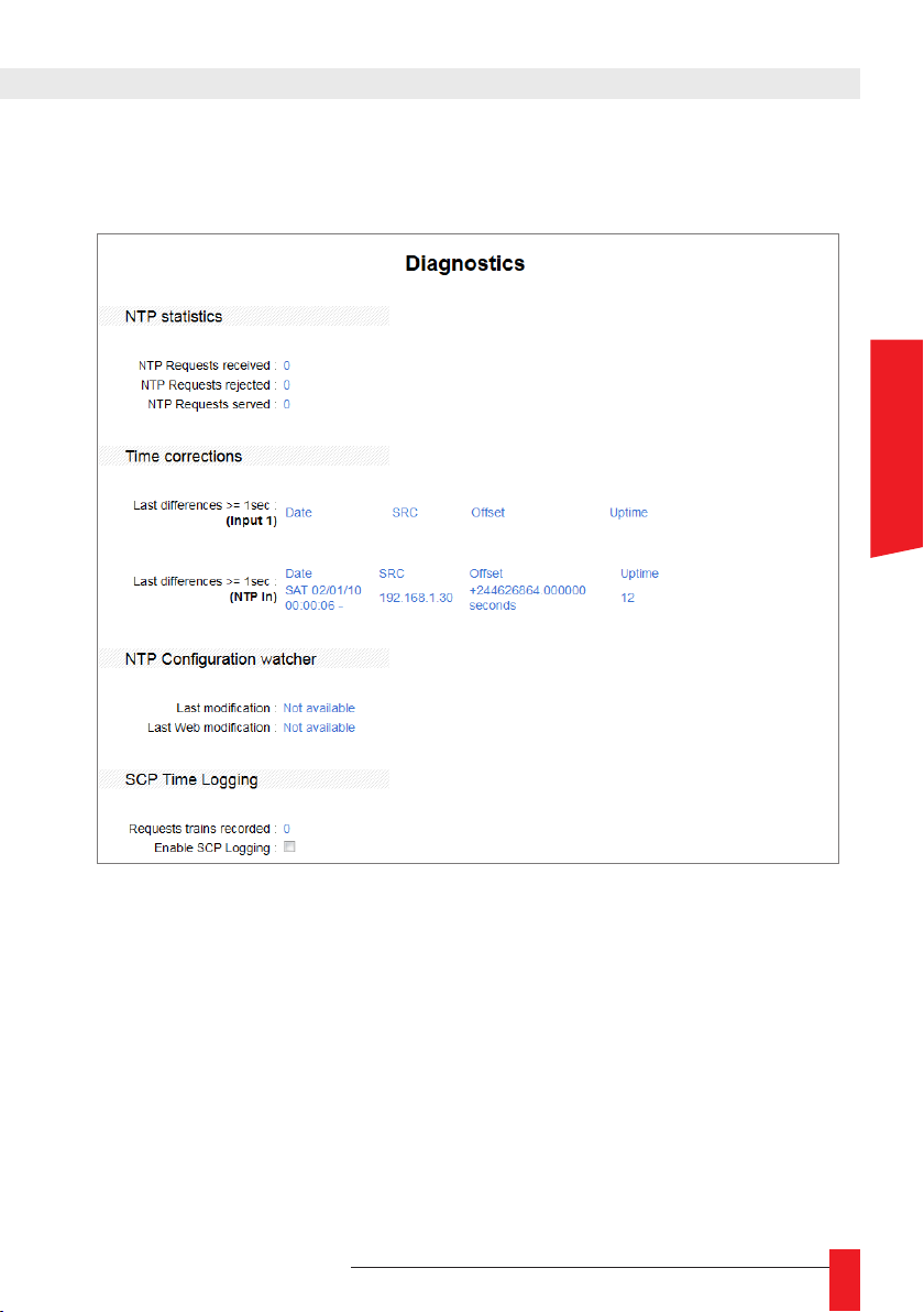
The Diagnostics Web page can be access via the address <IP>/html/_diag.html.
It contains diagnostics information and allows launching tests on the network module.
ENGLISH
NTP statistics
► NTP Requests received indicates the number of queries received by the network
module since startup..
► NTP Requests rejected indicates the number of queries rejected by the network
module since startup.
► NTP Requests served indicates the number of answers sent by the network module
since startup.
Time corrections
This part provides a table logging time leaps over one second per synchronization
input.
► Date is the internal date before the leap.
► SRC is the IP address of the NTP synchronization source server at the time of the
leap.
MDE-LEDI-NETWORK-TDS-4099V1.0
53
Page 54
► Offset is the new time minus the former time.
► Uptime is the functioning duration of the server at the time of the leap.
NTP Conguration watcher
That part is exclusively used by Gorgy Timing. It is not nalized in the provided software.
SCP Time Logging
► Enable SCP Logging activates the detailed log of the NTP answers by the client on
a SD card.
► Requests trains recorded is the number of exchanges recorded.
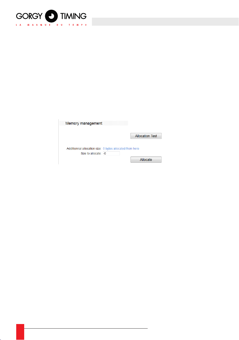
Memory management
► The Allocation Test button displays the volatile memory available on the network
module.
► Additionnal allocation size is the number of octets taken from the volatile memory by the
Allocate
button on the network module.
► Size to allocate is the number of octets to be taken from the volatile memory avai-
lable on the network module by the Allocate button.
► The Allocate button allows to reduce/return the quantity of volatile memory available
on the network module.
54
MDE-LEDI-NETWORK-TDS-4099V1.0
Page 55
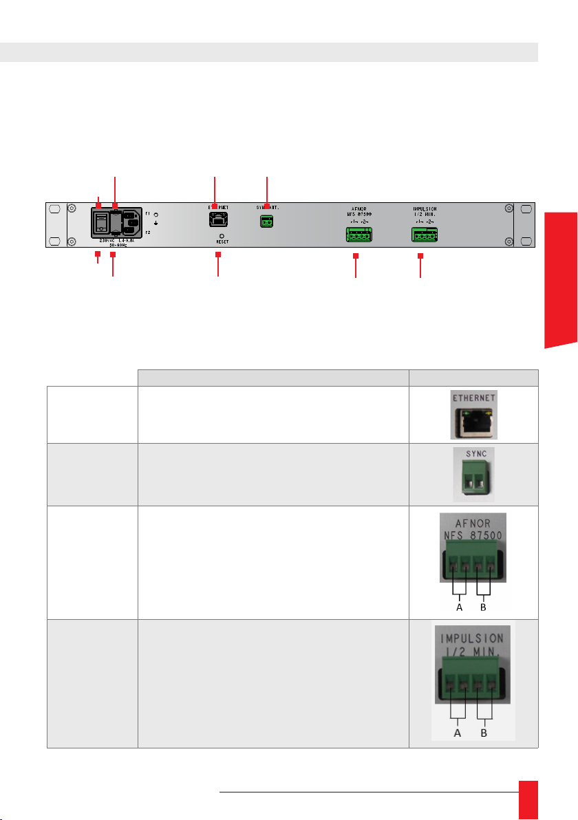
6. APPENDIX A – CONNECTIONS
This section contains a description of every possible connection on the
LEDI® NETWORK
TDS V1. All the connections are made at the back of the device.
.
FUSES
T-2A
ON
OFF
Management
and NTP
RESET230VAC
DCF/GPS
Sync. Ant
OUTPUT CARDS
The table below details the available equipment for each input/output port of the device as
well as the number and location of the useful signals.
Coupler/Signals Connections
Management and
NTP input/output
DCF/GPS input
RJ45 plug
Antenna
ENGLISH
AFNOR Output
NFS 87500/IRIG-B
POLARIZED
IMPULSIONS
Output
MDE-LEDI-NETWORK-TDS-4099V1.0
4 point screwed terminal
2 identical signals
No polarity
4 point screwed terminal
2 identical signals
No polarity
55
Page 56
6.1. DCF-GPS ANTENNA
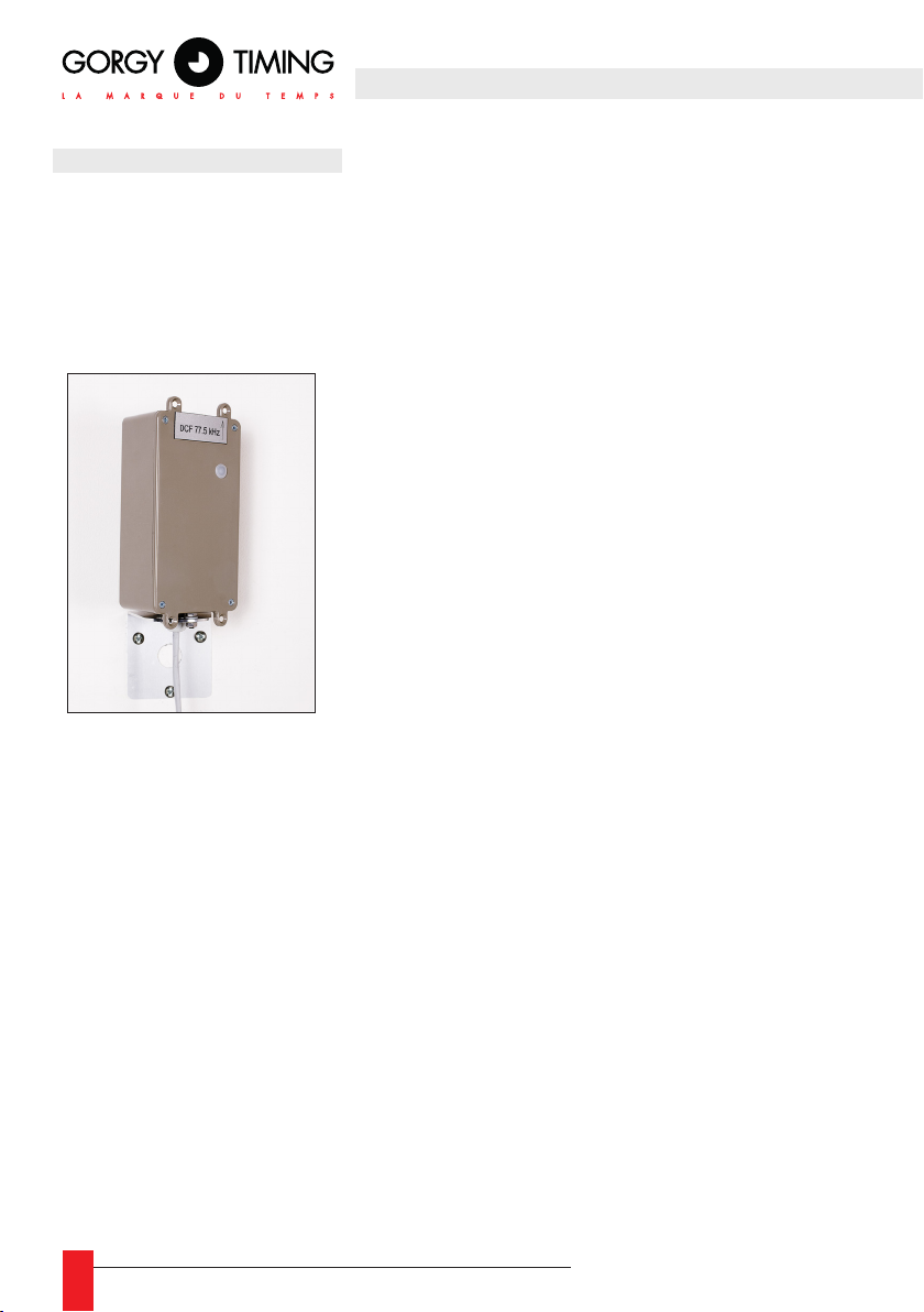
External dimensions of the rack:
Height: 150mm – Width: 80mm – Depth: 50mm
IP 54
► Install away from interference sources such as neon lights, computer screens, etc..
6.1.1. DCF Antenna Réf : 3D6 (four meters cable included)
Receipt frequency: 77.5 kHz
► Install the antenna vertically, then rotate it to get
a ashing of the indicator at the rhythm of one ash per
second and an extinction every minutes (in theory, the
antenna has to be positioned facing the direction of the
transmitter located near Frankfurt in Germany).
☛ The antenna must be placed outside the building
to optimize the radio signal reception.
☛ If reception conditions are right, the receiver time
setting requires less than 4 minutes.
☛ If the time setting would not be done after fteen minutes, it is
recommended to look for another location..
DCF Antenna characteristics
► Maximum screened two-core cable length: 100m
► Maximum distance from the DCF transmitter (Frankfort – Germany) or TDF trans-
mitter (Allouis – Cher): 200 km
(These are maximum values; the actual values may vary with the surrounding land
form and atmospheric conditions).
6.1.2. Gps ANTENNA CONVERTER UNIT
Ref: 3G and 3G1 (10m cable included)
► The antena must be placed outside and at the top of the building so as to get the wider
possible reception angle.
☛ Any building or rise superior to 5 degrees above the horizon line may
screen one or several satellites thus reducing the antenna’s performances.
56
MDE-LEDI-NETWORK-TDS-4099V1.0
Page 57
☛ Although it is not much perturbed by other systems, it is recommended
to avoid installing the antenna directly below a radar.
► Install the antenna vertically. No specic orientation is required.
► The green indicator must be ashing every second to indicate reception of at least
one satellite signal. The ashing duration of the green light varies from 0ms to 200ms
depending on the number of satellite signals received.
► The red indicator ashes every second once the GPS system receives the time indi-
cation. The ashing duration of the red light depends on bits transmitted at the DCF77
format (100ms for a “0” and 200ms for a “1”, no ashing at second 59).
► In some cases (before 2018), the green and red indicators could overlap, thus creating
an “orange” light.
► The GPS code is taken into account if the number of satellites is superior to 2.
► If after reception, the number of satellites remains below 3, the DCF code is stopped
after 20 seconds.
► The setting up of the receptor time must be done between 12 and 15 minutes.
► In the case where the time setup would not be done after half an hour, unplug the
antenna then plug it back in.
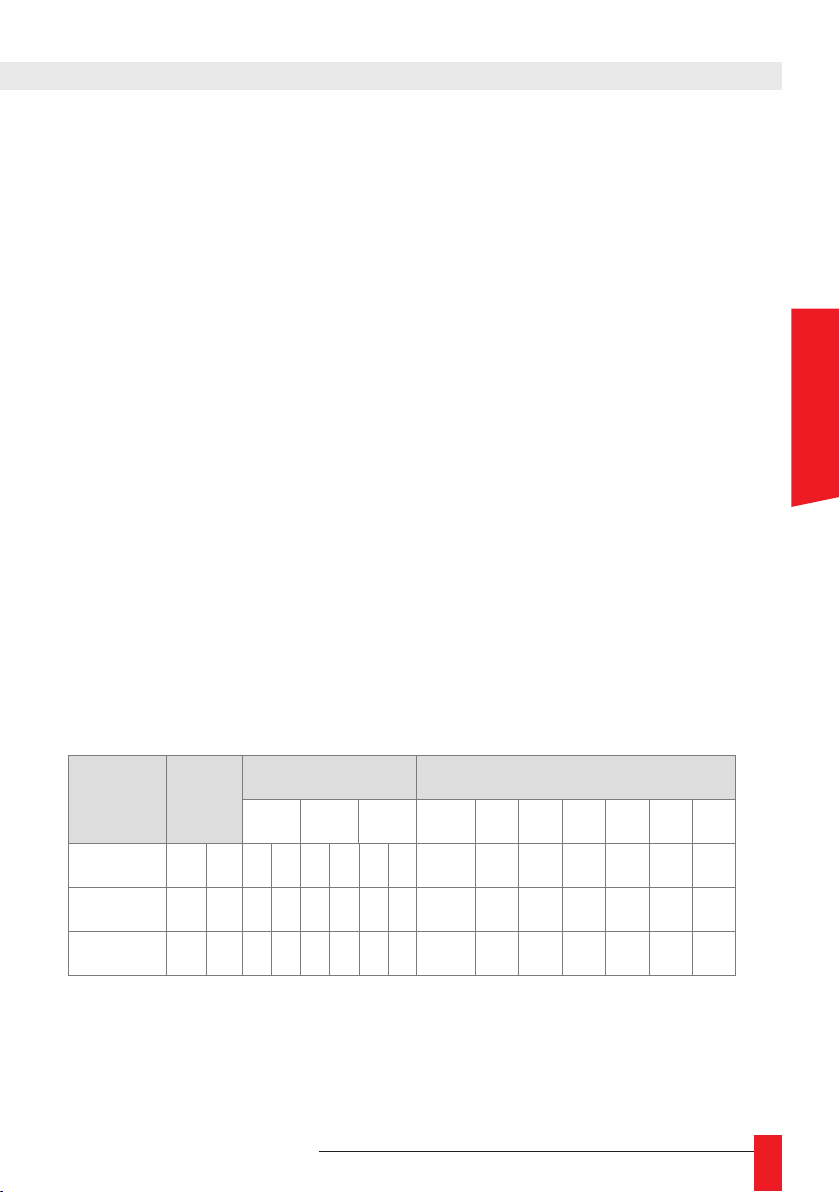
► 3G1 antenna time shift switch
Without
SW1
Positions 1 2 1 2 1 2 1 2 3 4 4 5 6 7 8
OFF X X X X X
ON X X X X X X X X X X
DST
DST TIME OFFSET
US EU AU 1/2h + - 8h 4h 2h 1h
GPS antenna characteristics
► Maximum length of each screened two-core cables: 100m.
► Works everywhere in the world.
ENGLISH
MDE-LEDI-NETWORK-TDS-4099V1.0
57
Page 58

6.2. AFNOR-NFS-87500 / IRIG-B OUTPUT
Time code AFNOR-NFS-87500/IRIG-B is delivered through a 4 points coupler.
An identical signal is available between the rst terminal (on the left) and the second terminal. A second signal identical to the rst is available between the third terminal and the
fourth terminal (on the right).
6.3. SERIAL IMPULSION OUTPUT
Impulsion signal is delivered through a 4 points coupler.
An identical signal is available between the rst terminal (on the left) and the second terminal. A second signal identical to the rst is available between the third terminal and the
fourth terminal (on the right).
58
MDE-LEDI-NETWORK-TDS-4099V1.0
Page 59
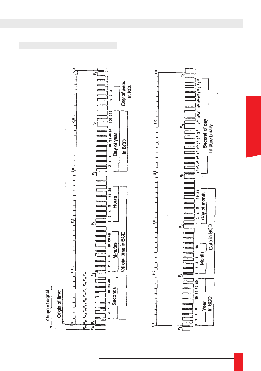
7.1. AFNOR/IRIG-B NFS87500
Frame format
7. APPENDIX B
OUTPUT CODES FORMAT
ENGLISH
MDE-LEDI-NETWORK-TDS-4099V1.0
59
Page 60
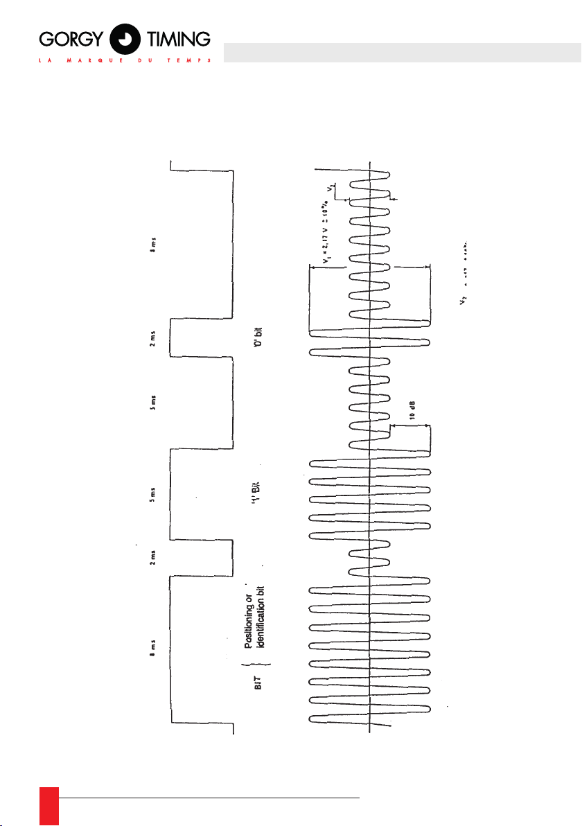
Bit encoding
The signal is modulated only on 'B' card. The 'T' card output signal has TTL level (5V).
60
MDE-LEDI-NETWORK-TDS-4099V1.0
Page 61
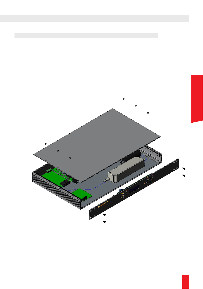
8. APPENDIX C – MAINTENANCE
8.1. CARD REPLACEMENT + IMPULSION CARD POWER
tools:
► Torx T15 screwdriver: front face (rack) or top plate (case)
► Torx T10 screwdriver: lid (rack) + front face (case) + output cards
► 5.5 wrench for M3 bolts: output cards + impulsion card power
► Unplug power
► Remove the four M3.5 screws from the front face
► Remove the six M3 screws from the lid
► Replace the defective card.
ENGLISH
MDE-LEDI-NETWORK-TDS-4099V1.0
61
Page 62
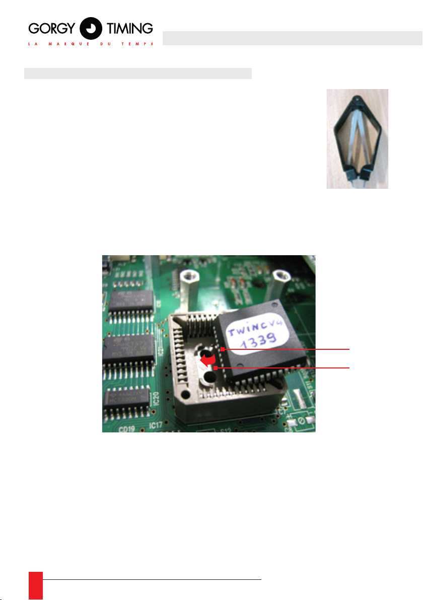
8.2. MICROCONTROLERS REPLACEMENT
Tools:
► Torx T15 screwdriver: front face (rack) or top plate (case)
► Torx T10 screwdriver: lid (rack) + front face (case) + output cards
► PLCC extractor: microcontroller
►
► Gorgy Timing reference: CIS8951RC2P
► Unplug every cable at the back of the product
► Remove the four M3.5 screws from the front face
► Remove the six M3 screws from the lid
► Use the PLCC extractor to remove the microcontroller
► Set in the new Microprocessor. Make sure to match the indexing slots
1
2
☛ On one side of the micro there is a dot (indicated by 1). The support
arrow (indicated by 2) must be on the same side as the dot.
Note: the system has two indexing slots:
The slanted angle of the micro must face one of the slanted corners of the
support..
62
MDE-LEDI-NETWORK-TDS-4099V1.0
Page 63
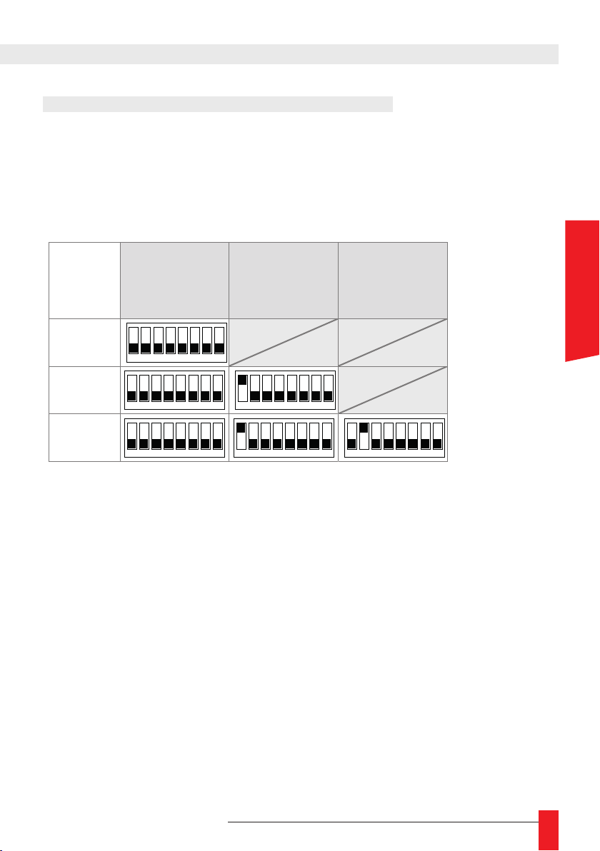
8.3. OUTPUT CARDS ADDRESSES SWITCHES
1
2 3 4 5 6 7 8
1
2 3 4 5 6 7 8
1
2 3 4 5 6 7 8
1
2 3 4 5 6 7 8
1
2 3 4 5 6 7 8
1
2 3 4 5 6 7 8
Each output card of the LEDI® NETWORK TDS V1 has an address which must be unique.
These addresses are determined by switches on each output card. When replacing/adding
a new card, the user must make sure that the cards addresses are unique.
Below is a recapitulative table of the addresses depending on the switches positions:
Output 1
(closest from
the mother
card)
1 output
2 outputs
3 outputs
► Switches are read at a binary format. Each switch’s power is to the second.
Output 2 Output 3
ENGLISH
MDE-LEDI-NETWORK-TDS-4099V1.0
63
Page 64
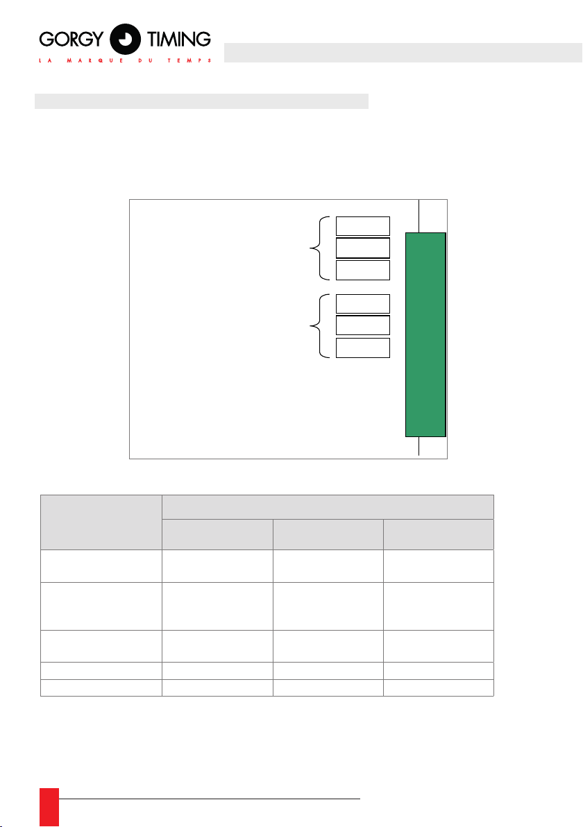
8.4. TOP & IRIG B DCLS TIME CODE OUTPUT
SW1
SW2
SW3
SW1
SW2
SW3
.
Sortie 4
Sortie 3
TOP and IRIG DCLS outputs cards can provide several signal formats:
► TTL
► Differential TTL (RS422)
► Phototransistors or static relays, depending on the card type.
OFF ON
Output 4
Output 3
.
For each output
Signal format
Switch 1 Switch 2 Switch 3
Phototransistor or
static relay
ON (Right) ON (Right) ON (Right)
RS422
Phototransistor or
ON (Right) OFF (Left) OFF (Left)
static relay
RS422
TTL differential
OFF (Left) OFF (Left) OFF (Left)
TTL
64
MDE-LEDI-NETWORK-TDS-4099V1.0
Page 65
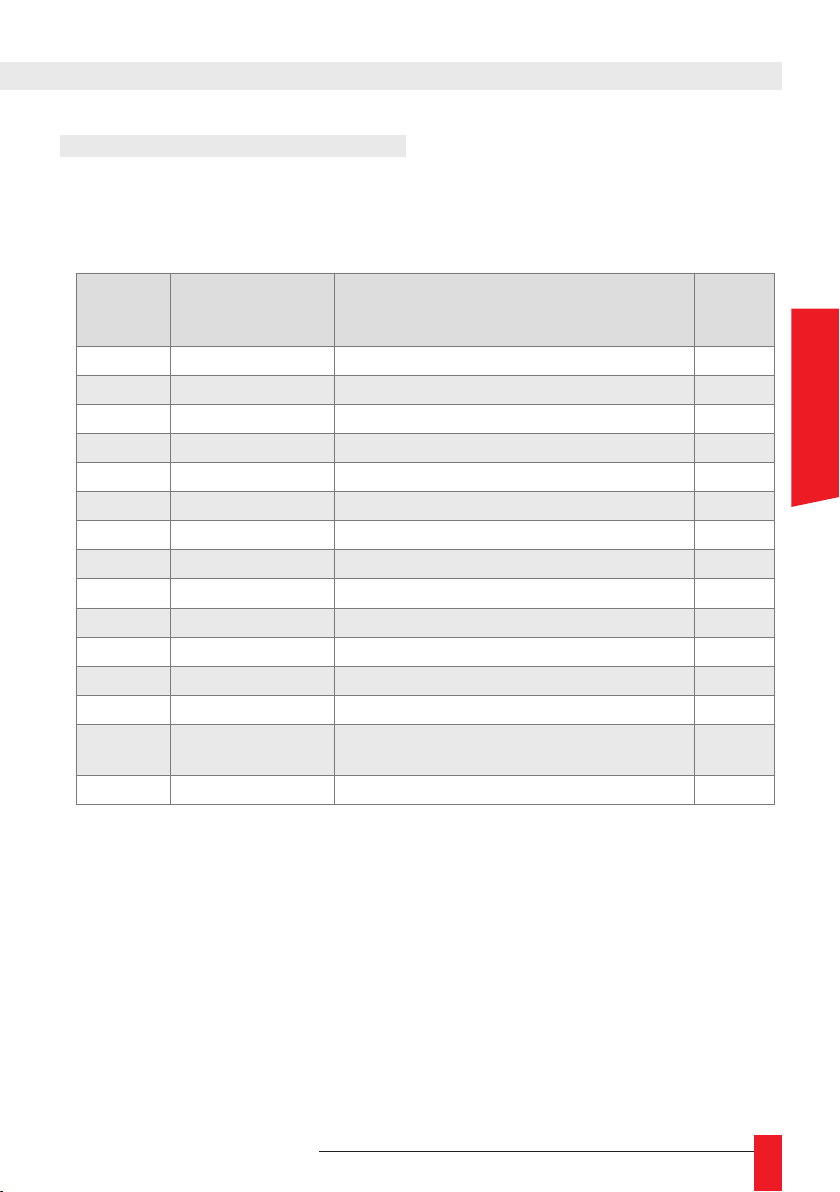
8.5. SUPERVISION PROTOCOLS
8.5.1. Syslog messages catalog
The table below depicts Syslog messages sent by the device.
Syslog
category
(value)
user (1) Conguration via la face avant A new conguration has been dened through the front LCD & buttons info (6)
user (1) Conguration via Telnet A new conguration has been dened through the Telnet interface info (6)
user (1) Conguration via page Web A new conguration has been dened in the \»Alarms\» Webpage info (6)
user (1) Conguration via page Web A new conguration has been dened in the \»Inputs\» Webpage info (6)
user (1) Conguration via page Web A new conguration has been dened in the \»Interface\» Webpage info (6)
user (1) Conguration via page Web A new conguration has been dened in the \»Network\» Webpage info (6)
user (1) Conguration via page Web A new conguration has been dened in the \»NTP\» Webpage info (6)
user (1) Conguration via page Web A new conguration has been dened in the \»Output\» Webpage info (6)
user (1) Conguration via page Web A new conguration has been dened in the \»SNMP\» Webpage info (6)
user (1) Conguration via page Web A new conguration has been dened in the \»NTP Statistics\» Webpage info (6)
kern (0) Restart System has restarted, reason : reset or power failure info (6)
kern (0) Restart System has restarted, reason : manual reconguration info (6)
auth (4) Secure web interface The secure web interface has been accessed info (6)
daemon (3) SNMP
daemon (3) Ethernet link Ethernet link error. Check the cable error (3)
Message category Sent text
A SNMP trap has been sent, with ID XX
XX est l’identiant du trap SNMP.
Syslog
sererity
(value)
notice (5)
ENGLISH
MDE-LEDI-NETWORK-TDS-4099V1.0
65
Page 66

9. APPENDIX D – FIXES
This section provides answers to the frequently asked questions about the use of your
NTP device. Before starting, please make sure that the GTNetworkManager2 is installed
on your computer.
I MADE A SCAN WITH GTNETWORKMANAGER2,
BUT I DON’T SEE ANY DEVICE!
► Check the cable connection. If the ETHERNET LEDs are visible the top left LED
should be ashing green. If not, the problem probably comes from a network connec-
tion or power issue.
► If you are using several VLAN (virtual local networks), please check that the device is
connected to the same VLAN as your computer.
► Connect your computer to the device via a direct cable. The device automatically
takes an IP address (format 169.254.x.y). Change the IP address of your computer
for an IP address of this format using a network mask 255.255.0.0
.
I CANNOT OPEN THE CONFIGURATION WEBPAGE!
► First, does GTNetworkManager2 detect the device?
YES
Your computer and the device must have the same IP scope and the same network
mask.
NO
See the question above.
► Did the browser found the web page (loading begins but fails partway)?
NO, THE PAGE CANNOT BE FOUND
If you are using “Internet Explorer”, go to:
Tools Internet Options Connections Network settings
The browser must not be using any proxy. Uncheck all boxes.
YES
The web page can be accessed, but the browser cannot load it.
Open a TELNET session:
Telnet < adresse ip> 9999
Login: root
Password: gtmt
Enter “factory_default” then refresh the web page.
66
MDE-LEDI-NETWORK-TDS-4099V1.0
Page 67

THE CONFIGURATION WEB PAGE DOES NOT SHOW ANY OUTPUT?
► Press “F5” to refresh the web page then return to the output panel. If the output still
does not appear, skip to the next step.
► Open a TELNET session:
Telnet < adresse ip> 9999
Login: root
Password: gtmt
"Enter “factory_default” then refresh the web page
► If the output still does not appear, remove the lid of the server. Check that the black
cables are correctly plugged and the switches setup (see Appendix C – MAINTENANCE 8.3 Output cards addresses switches).
THE SCREEN DISPLAYS “NO TIME CODE!”
► “NO TIME CODE!”: The device is not synchronized; check your time source.
► “no time code!” followed by the date: if your device receives the time code, check
inside the “input” panel in the conguration web page that the “Enable autonomous
mode” is unchecked.
ENGLISH
MDE-LEDI-NETWORK-TDS-4099V1.0
67
Page 68

GORGY TIMING SAS
Quartier Beauregard
38350 La Mure d'Isère (Grenoble France)
Phone: +33 4 76 30 48 20 Fax: +33 4 76 30 85 33
email: [email protected] - www.gorgy-timing.com
TECHNICAL SUPPORT
+33 476 30 48 20
RADIO TIMING®, LEDI®, LEDICA®, HANDI® are trademarks by GORGY TIMING.
Number of statement for training provider activity : 82 38 04877 38
Gorgy Timing RC74B38 - Any technical, aesthetic, color modications can be made without notice.
68
MDE-LEDI-NETWORK-TDS-4099V1.0
 Loading...