

Page 1
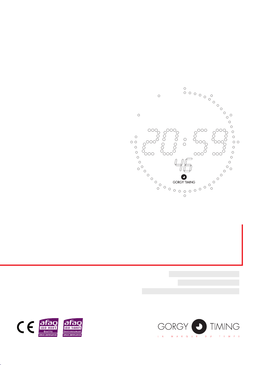
LEDI®1.60(S)
BOÎTIER PIVOTANT - BOÎTIER ENCASTRABLE - BOÎTIER STANDARD
PIVOTING CASE - FLUSH-MOUNTABLE CASE - STANDARD CASE
MODE D’EMPLOI - PAGE 3
USER GUIDE - PAGE 15
BEDIENUNGSANLEITUNG - SEITE 29
Page 2
CONSIGNES DE SÉCURITÉ IMPORTANTES
ATTENTION ! Avant de commencer l’installation de votre matériel, lisez attentivement la section suivante qui décrit les consignes de sécurité à respecter au cours
de l’installation.
L’installation électrique sur laquelle le matériel est raccordé doit être réalisée
conformément à la norme NF C 15-100 .
Cet appareil ne comporte pas d’interrupteur d’alimentation primaire : un dispositif
de coupure (disjoncteur ou interrupteur sectionneur), rapidement accessible, doit
être incorporé dans l’installation de câblage. Ce dispositif doit supporter les valeurs de tension et courant nominales indiquées sur l’appareil.
En Europe : dans le cadre de la protection des individus et de l'environnement,
il vous incombe de vous débarrasser de cet équipement dans un site de collecte
prévu à cet effet (séparément des ordures ménagères). Pour de plus amples
informations, contactez votre revendeur, votre site de collecte ou les autorités
locales compétentes.
Toute modication ou ouverture du produit sans l’accord du SAV entraîne la perte
de la garantie.
Toute opération de maintenance doit être effectuée hors-tension, y compris pour
les systèmes reliés aux éventuelles sorties sur relais.
D’une façon générale, les câbles de puissance (alimentation 220V) et de signaux
(information horaire) ne doivent pas être trop proches les uns des autres, pour
éviter toute perturbation. (garder quelques centimètres de distance)
Gorgy Timing décline toute responsabilité en cas d’accidents ou de dommages
provoqués par une mauvaise utilisation du produit.
Les produits GORGY TIMING sont conformes aux normes : CE, EN 60950, EN 55022,
EN 50024.
2
MDE-LEDI160S-1012V1.0
Page 3
SOMMAIRE
1. CARACTERISTIQUES ................................................................................................... 4
1.1. Version autonome ................................................................................................................ 5
1.2. Version réceptrice Min. parallèle .......................................................................................... 5
1.3. Version réceptrice ½ Min série ............................................................................................. 5
1.4. Version réceptrice AFNOR NFS 87500 ................................................................................ 5
2. FIXATION ....................................................................................................................... 6
2.1 Boîtier standard ..................................................................................................................... 6
2.2 Boîtier encastrable ................................................................................................................. 6
2.3 Boîtier étanche ...................................................................................................................... 7
3. BRANCHEMENTS ........................................................................................................ 8
3.1 Boîtier STANDARD et ENCASTRABLE ................................................................................8
3.2. Boîtier ETANCHE .................................................................................................................9
3.3. Boîtier PIVOTANT à poser sur table ..................................................................................... 9
. MISE EN SERVICE ...................................................................................................... 10
FRANCAIS
5. OPTIONS ......................................................................................................................11
5.1. OPTION CHRONOMETRE ................................................................................................11
5.1.1. mode chronométre ..................................................................................................11
5.1.2. Mode décomptage ...................................................................................................11
5.1.3. Branchements boîtier encastrable chrono .............................................................. 12
5.2. OPTION ASCII RS232 ou RS422/485 ................................................................................ 12
5.2.1. Mode émetteur ou Uni-directionnel ........................................................................ 12
5.2.2. Mode récepteur ...................................................................................................... 13
5.2.3. Mode bi-directionnel ............................................................................................... 13
MDE-LEDI160S-1012V1.0
3
Page 4

1. CARACTERISTIQUES
Boîtier ETANCHE
195
Epaisseur : 120
Boîtier PIVOTANT
Boîtier STANDARD
115
Boîtier ETANCHE
Epaisseur : 120
115
50
Boîtier ENCASTRABLE
57
144
160
à poser sur table
132.5
181
165
OFF
ON
+
-
Prog.
140
130
195
195
( cotes : mm)
4
MDE-LEDI160S-1012V1.0
Page 5

► Afchage numérique Heure, Minute, Seconde (option « S »), 7 segments à diodes
électroluminescentes.
► Hauteur des chiffres heure et minute : 18mm
► Inclinaison des chiffres 10°
► Lisibilité : 7 mètres
► Alimentation 230 VAC (+/-10%) 50-60Hz. (par transformateur déporté)
► Consommation : 6 Watts
► Sauvegarde des informations horaires de 48 heures minimum par batterie Cd-Ni incorporée.
VERSIONS EXISTANTES :
1.1. VERSION AUTONOME
► Base de temps à quartz incorporé 3.6864Mhz, stabilité +/-0.02 sec/24h entre 20°C
et 30°C
1.2. VERSION RÉCEPTRICE MIN. PARALLÈLE
► Impulsions minute inversée 24V chaque minute. Durée impulsionnelle : 0.1sec.
► Consommation impulsionnelle : 6 mA / 24V
1.3. VERSION RÉCEPTRICE ½ MIN SÉRIE
► Branchement série avec un shunt extérieur de 39 Ohms.
► Impulsion ½ min. inversée chaque ½ min.
► Durée impulsionnelle 0.1 sec.
► Consommation impulsionnelle : 1.25 V
► Intensité en ligne : 60 mA à 120 mA
FRANCAIS
1.4. VERSION RÉCEPTRICE AFNOR NFS 87500
► Niveau d’entrée nominal : 2.2Vcc
► Impédance d’entrée : 3.5 Kohms
► Tension minimale d’entrée :70 mVcc
MDE-LEDI160S-1012V1.0
5
Page 6
2.1 BOÎTIER STANDARD
103.5
78
65
30
Clock attachment
Fig.1
Standard case
40
127
Ouverture
murale
Fig.2
127
57
37.5
144
160
3
Boîtier ENCASTRABLE
40
127
Wall
opening
Fig.2
127
57
37.5
144
160
3
Flush-mountable case
103.5
78
65
30
Einhängen
der Uhr
Fig.1
Standardgehäuse
40
127
Wall
opening
Fig.2
127
57
37.5
144
160
3
Einbaugehäuse
40
127
Wall
opening
Fig.2
127
132.5
57
37.5
144
160
3
Flush-mountable case
40
127
Wall
opening
Fig.2
127
132.5
57
37.5
144
160
3
Einbaugehäuse
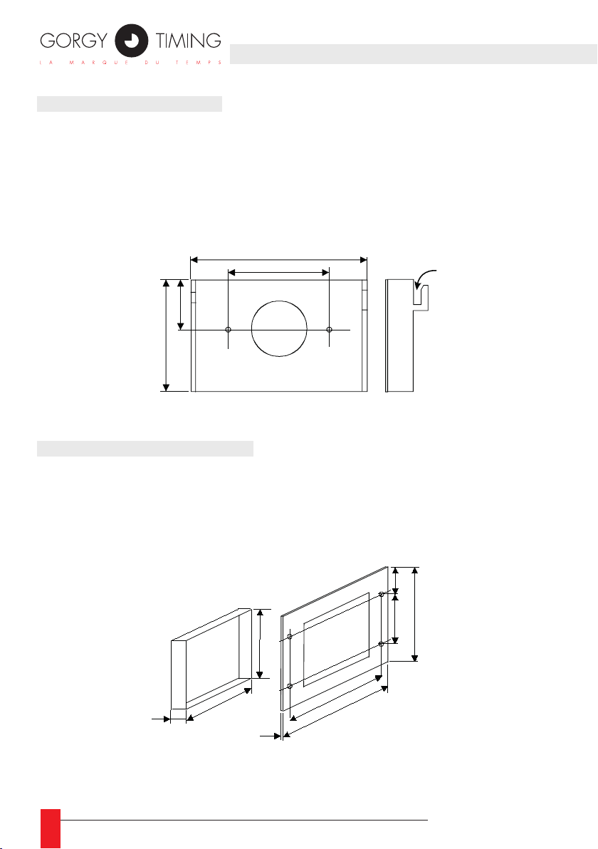
► Préparation du support mural pour la xation de l’équerre, prévoir une marge de
15mm minimum entre le haut du boîtier et le plafond.
► Fixer l’équerre sur le support mural à l’aide de 2 vis M4.
► Accrocher le boîtier sur l’équerre.
2.2 BOÎTIER ENCASTRABLE
► Préparation du support mural : ouverture 127 X 127mm
65
► Fixer la face avant sur le support à l’aide de 4 vis M4.
40
Boîtier STANDARD
Fig.1
30
Boîtier ENCASTRABLE
Fig.2
127
Ouverture
murale
127
103.5
78
3
Accrochage
de l'horloge
37.5
57
144
160
132.5
2. FIXATION
6
MDE-LEDI160S-1012V1.0
Page 7
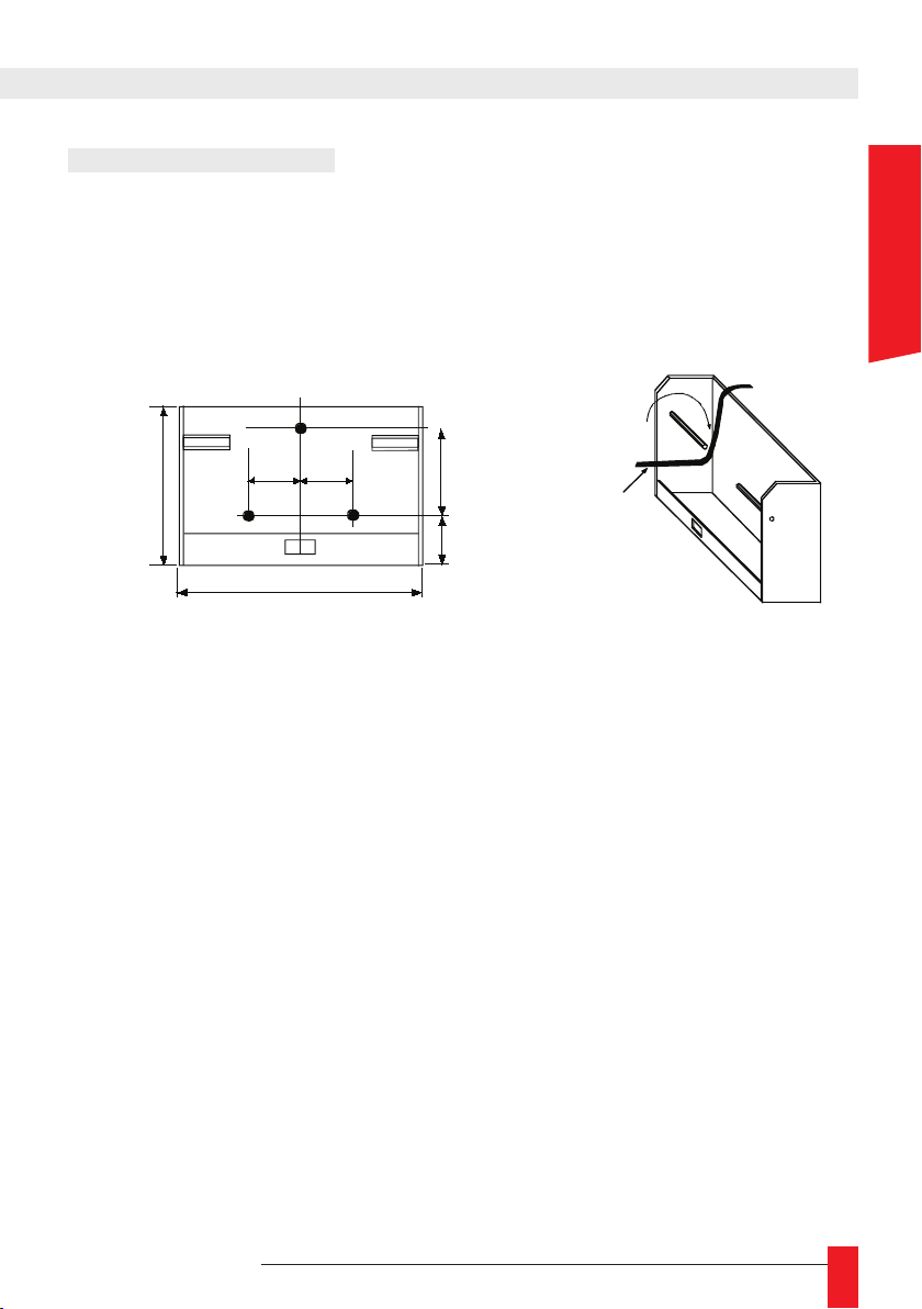
2.3 BOÎTIER ÉTANCHE
Accrochage
du boitier
2 -
1 - Faire
passer les fils
de la façon
suivante
27
40
90
108
27
25
Fig.3
Support
à fixer :
Boîtier ETANCHE
► Préparation et perçage du support mural.
► Fixer le « support LEDI » à l’aide de 3 vis M5.
► Accrocher et clipser l’horloge sur son support.
FRANCAIS
MDE-LEDI160S-1012V1.0
7
Page 8

BRANCHEMENTS
ALIMENTATION
( B4 )
Entrée
CHRONOMETRE
( B2 )
Borne
ASCII
( B3 )
3 2 1
Entrée de
SYNCHRONISATION
( B1 )
Switch
ON/OFF
( SW1 )
Bouton Poussoir
" + "
Bouton Poussoir
" - "
Bouton Poussoir
" PROG "
3.1 BOÎTIER STANDARD ET ENCASTRABLE
3. BRANCHEMENTS
8
► Brancher l’alimentation 230VAC 50-60Hz.
► Connecter l’entrée de synchronisation sur la borne B1, si nécessaire (aucune polarité).
► Options : chronomètre- B2, ou ASCII – B3.
► Option chargeur batterie : Brancher les deux ls rouge +, noir - du «chargeur batte-
rie» en 12VDC ou 24VDC sur le bornier 2pts (sans ce branchement l’afchage de
l’horloge s’éteindra dès que la batterie sera déchargée)
► Basculer le coupe batterie SW1 sur la position ON (position basse).
MDE-LEDI160S-1012V1.0
Page 9

3.2. BOÎTIER ETANCHE
Toutes les connexions se font à l’arrière sans ouvrir le boîtier. Se raccorder suivant les
repères des câbles.
► Brancher l’alimentation 230VAC 50-60Hz.
► Brancher l’entrée de synchronisation puis les options (entrée ASCII, chronomètre …)
☛ Cette horloge est obligatoirement réceptrice, elle ne peut pas être
autonome et ne possède pas de réglage de luminosité manuelle.
3.3. BOÎTIER PIVOTANT À POSER SUR TABLE
► Toutes les connexions se font sans ouvrir le boîtier. Se raccorder suivant les re-
pères des câbles.
► Brancher l’alimentation 230VAC 50-60Hz.
► Basculer le coupe batterie SW1 sur la position ON (position basse).
☛ Si l’afchage de l’horloge reste éteinte attendre quelques minutes an
que la batterie interne soit chargée.
FRANCAIS
MDE-LEDI160S-1012V1.0
9
Page 10
► La mise à l’heure se fait au moyen de trois touches «+ «, « –» et « PROG « acces-
sibles par la face arrière ou sur le coté (boîtier pivotant ).
► A chaque pression sur la touche « PROG » une partie de l’afchage se met à cligno-
ter, la modication de la partie clignotante se fait à l’aide des touches «+ « et «–»
(délement rapide en restant appuyé sur la touche).
► Cycle de réglage : 1 Réglage des heures
2 Réglage des minutes
► Le réglage de luminosité s’effectue manuellement sur les touches «+» et «–» en
dehors du cycle de mise à l’heure.
SYNCHRONISATION :
► Si les minutes n’ont pas été modiées : Une pression sur « PROG » validera la
nouvelle heure programmée sans modier la synchronisation initiale (ex :modication de l’alternance heure/température ou changement d’heure saisonnier pour des
horloges autonomes).
► Si les minutes ont été modiées : Une pression sur « PROG » fera clignoter tout
l’afchage indiquant que l’horloge est en phase de synchronisation. Une deuxième
pression sur « PROG » permettre de synchroniser l’horloge (exercer cette deu-
xième pression au moment du top minute donné par une référence de temps ex.
horloge parlante n° tel.3699). L’afchage s’arrête alors de clignoter.
10
MDE-LEDI160S-1012V1.0
Page 11
5. OPTIONS
5.1. OPTION CHRONOMETRE
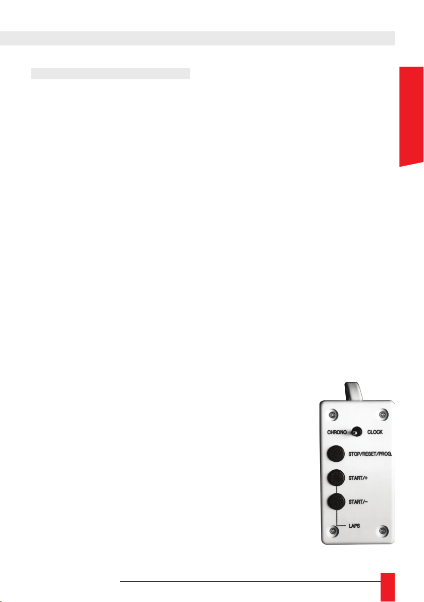
► Un commutateur clock/chrono permet de passer de l’indication de l’heure en posi-
tion “clock” à la fonction chronomètre en position “chrono”.
► Deux utilisations en mode chronomètre sont possibles :
► Utilisation chronométrage (comptage du temps)
► Utilisation décomptage (décomptage du temps)
FONCTIONNEMENT :
On peut afcher ou non une heure de consigne.
5.1.1. mode chronométre
► Pas d’heure de consigne :
Faire “START /+” (chronométrage), le chronomètre va partir de zéro et va déler
indéniment jusqu’à la prochaine pression sur la touche “STOP”.
► Une heure de consigne est choisie :
Appuyer sur la touche “PROG” (cette fonction n’est accessible que dans le cas ou le
chronomètre est stoppé et à zéro) puis afcher l’heure désirée à l’aide des touches “+” et
“-“ (à chaque pression sur la touche “PROG” une partie de l’afchage se met à clignoter,
régler successivement les heures puis les minutes puis les secondes).
A la n de cette programmation appuyer sur la touche “START/+”, l’afchage va partir de l’heure programmée et va déler indéniment jusqu’à la prochaine pression
sur la touche “STOP”.
5.1.2. Mode décomptage
► Pas d’heure de consigne :
Faire “START /-” (décomptage), le chronomètre va partir d’un
temps donné et va déler jusqu’à zéro ou jusqu’à la prochaine
pression sur la touche “STOP”.
FRANCAIS
► Une heure de consigne est choisie :
Appuyer sur la touche “PROG” (cette fonction n’est accessible
que dans le cas ou le chronomètre est stoppé et à zéro) puis
afcher l’heure désirée à l’aide des touches “+” et “-“ (à chaque
pression sur la touche “PROG” une partie de l’afchage se met
à clignoter, régler successivement les heures puis les minutes
puis les secondes).
A la n de cette programmation appuyer sur la touche “START/-”,
l’afchage va partir de l’heure programmée puis s’arrête automatiquement à zéro et réafche l’heure de consigne programmée.
MDE-LEDI160S-1012V1.0
11
Page 12

☛ On peut aussi avoir le temps intermédiaire en maintenant une pression
1
sur une des touches “LAPS” du boîtier chrono.
☛ En comptage ou en décomptage lorsque une heure de consigne est
programmée, le chronomètre peut être arrêté puis relancé à tout moment
par pression sur les touches “STOP” puis “ START” sans modier l’heure de
consigne initialement programmée.
☛ Il est possible de déclencher à la seconde zéro un contact sec à l’aide
de l’option top (nous consulter)
5.1.3. Branchements boîtier encastrable chrono
Correspondance des pins de la SUBD9 mâle en sortie du boîtier chronomètre :
► Pin1 : PROG
► Pin2 : +
► Pin3 : -
► Pin4 : Commutateur horloge/chrono
► Pin5 : Masse
5.2. OPTION ASCII RS232 OU RS422/485
Liaison ASCII RS232C sur la borne B3 Liaison ASCII RS422/485 sur la borne B3
1 : GND 1 : E/S 2 : TXD 2 : E/S +
3 : RXD 3 : GND
CETTE OPTION FONCTIONNE SELON 3 MODES
5.2.1. Mode émetteur ou Uni-directionnel
Dans ce mode l’horloge émet un code (conguration : 2400 bauds, format 8 bits, parité
paire, 1 stop bit) en 2 parties :
► 1) – L’information horaire sous la forme :
STX jour de la semaine SP jour du mois/mois/année SP SP Heure :minute :seconde CR
► 2) – Les informations états du chronomètre, température, luminosité etc…
La première partie de l’information sert par exemple à synchroniser un ordinateur (dans
ce cas ne pas tenir compte de la deuxième partie).
L’information complète permet d’asservir une autre horloge à la première.
12
MDE-LEDI160S-1012V1.0
Page 13

5.2.2. Mode récepteur
Dans ce mode l’horloge fonctionne en mode autonome et se met à l’heure par rapport
au code ASCII reçu (conguration : 2400 bauds, format 8 bits, parité paire, 1 stop bit).
Ce code ASCII peut être :
► 1) – L’information horaire sous la forme :
STX jour de la semaine SP jour du mois/mois/année SP SP Heure :minute :seconde CR
Généré soit par le RT3000 ou le RADIO TIMING ASCII ou tout autre générateur de
code ASCII.
► 2) – Soit l’information provenant d’une autre horloge de même type fonctionnant en
mode émetteur, dans ce cas l’horloge est parfaitement asservie à cette dernière.
5.2.3. Mode bi-directionnel
Dans ce mode le message horaire codé en ASCII est transmis après réception d’un
caractère de reconnaissance ( caractère « D »)
(conguration : 2400 bauds, format 8 bits, parité paire, 1 stop bit)
► Message transmis :
STX centième de seconde SP jour de la semaine SP jour du mois/mois/année SP
SP Heure :minute :seconde CR
Ex : 76 VEN 03/02/90 15 :14 :45 ce qui veut dire que la seconde correspondante à
ce message est passé de 76 centièmes de seconde au moment de la réception du
caractère « D ».
☛ Dans le cas de la LEDI 1/60 (indiquant uniquement l’information heure
et minute) l’information date est remplacée par des zéros et le jour de la
semaine en alphanumérique est remplacé par 3 espaces. Toutefois si cette
horloge est réceptrice du code AFNOR NFS 87-500 ou radio synchronisée ,
l’information date est générée.
FRANCAIS
☛ En cas de coupure secteur l’afchage s’éteint mais l’horloge continue
de fonctionner grâce à sa batterie interne. (les sorties tops horaires et la
☛ Pour les horloges réceptrice du code ASCII si le message reçu n’est
pas de bonne conguration, une mise à l’heure manuelle à la mise en
service peut être nécessaire, dès que le message ASCII est reçu, l’horloge
compense un éventuel décalage avec l’heure de référence. (réglage
MDE-LEDI160S-1012V1.0
sortie ASCII ne sont plus générées).
impossible en version étanche)
13
Page 14

GORGY TIMING SAS
Quartier Beauregard
38350 La Mure d'Isère (Grenoble France)
Phone: +33 4 76 30 48 20 Fax: +33 4 76 30 85 33
email: [email protected] - www.gorgy-timing.com
SUPPORT TECHNIQUE
DEPUIS LA FRANCE SUR UN POSTE FIXE :
RADIO TIMING®, LEDI ®, LEDI CA®, HANDI ® sont des marques déposées GORGY TIMING.
Numéro de déclaration d’activité de prestataire de formation : 82 38 04877 38
GORGY TIMING RC 74 B 38 - Toutes modications d'ordre technique ou esthétique peuvent être apportées sans préavis.
14
MDE-LEDI160S-1012V1.0
Page 15
USER GUIDE
LEDI®1.60(S)
PIVOTING CASE
FLUSH-MOUNTABLE CASE
STANDARD CASE
ENGLISH
MDE-LEDI160S-1012V1.0
15
Page 16
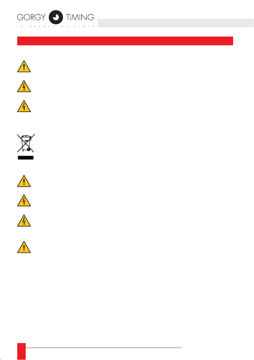
IMPORTANT SAFETY INSTRUCTIONS
WARNING! Read the section that follows very carefully before installing your equipment. It gives the safety instructions to follow during installation.
The electrical installation to which the equipment is connected must comply with
the NF C 15-100 standard.
This device does not have a primary power switch. A power protection system
(circuit-breaker or disconnecting switch), that is easy to access must be built into
the wiring installation. This device must support the nominal voltage and current
values specied on the clock.
In Europe: to comply with European regulations on the protection of persons and
the environment, you must dispose of this equipment in a collection site provided
for this purpose (separately from household waste). Contact your reseller, collection site or the competent lcoal authorities for more information.
Modifying or opening the product without the consent of the Customer service
department will void the warranty.
All maintenance operation shall be conducted with power shut off, including systems connected on relay outputs if any.
Generally, the power cable (220V) and transmission cable (of time signal) shall
not be very close to each other, so as to avoid interference (keep the distance of
a few centimeters).
Gorgy Timing disclaims all responsibility in case of accident or damage caused by
an improper use of the product.
GORGY TIMING products are compliant with the following standards: CE, EN 60950,
EN 55022, EN 50024
16
MDE-LEDI160S-1012V1.0
Page 17

CONTENTS
1. CHARACTERISTICS .................................................................................................. 18
1.1. Stand-alone version ............................................................................................................ 19
1.2. Parallel Min. receiving version ............................................................................................ 19
1.3. Serial ½ Min. receiving version ........................................................................................... 19
1.4. AFNOR NFS 87500 receiving version ................................................................................ 19
2. INSTALLATION ............................................................................................................ 20
2.1. Standard case .................................................................................................................... 20
2.2. Flush-mountable case ........................................................................................................ 20
2.3. Waterproof case ................................................................................................................. 21
3. CONNECTIONS .......................................................................................................... 22
3.1. STANDARD and FLUSH-MOUNTABLE cases: .................................................................. 22
3.2. WATERPROOF case: ......................................................................................................... 23
3.3. PIVOTING case to be placed on a table: ........................................................................... 23
4. START-UP ................................................................................................................... 24
5. OPTIONS ..................................................................................................................... 25
5.1. timer option ........................................................................................................................ 25
5.1.1. Stopwatch function ................................................................................................. 25
5.1.2. Count-down ............................................................................................................ 25
5.1.3. Connection for ush-mountable timer ..................................................................... 26
5.2. ASCII RS232 or RS422/485 OPTIONS ............................................................................. 26
5.2.2. Emission or unidirectional mode ............................................................................. 26
5.2.2. Receiving mode ...................................................................................................... 27
5.2.3. Bi-directional mode ................................................................................................. 27
ENGLISH
MDE-LEDI160S-1012V1.0
17
Page 18
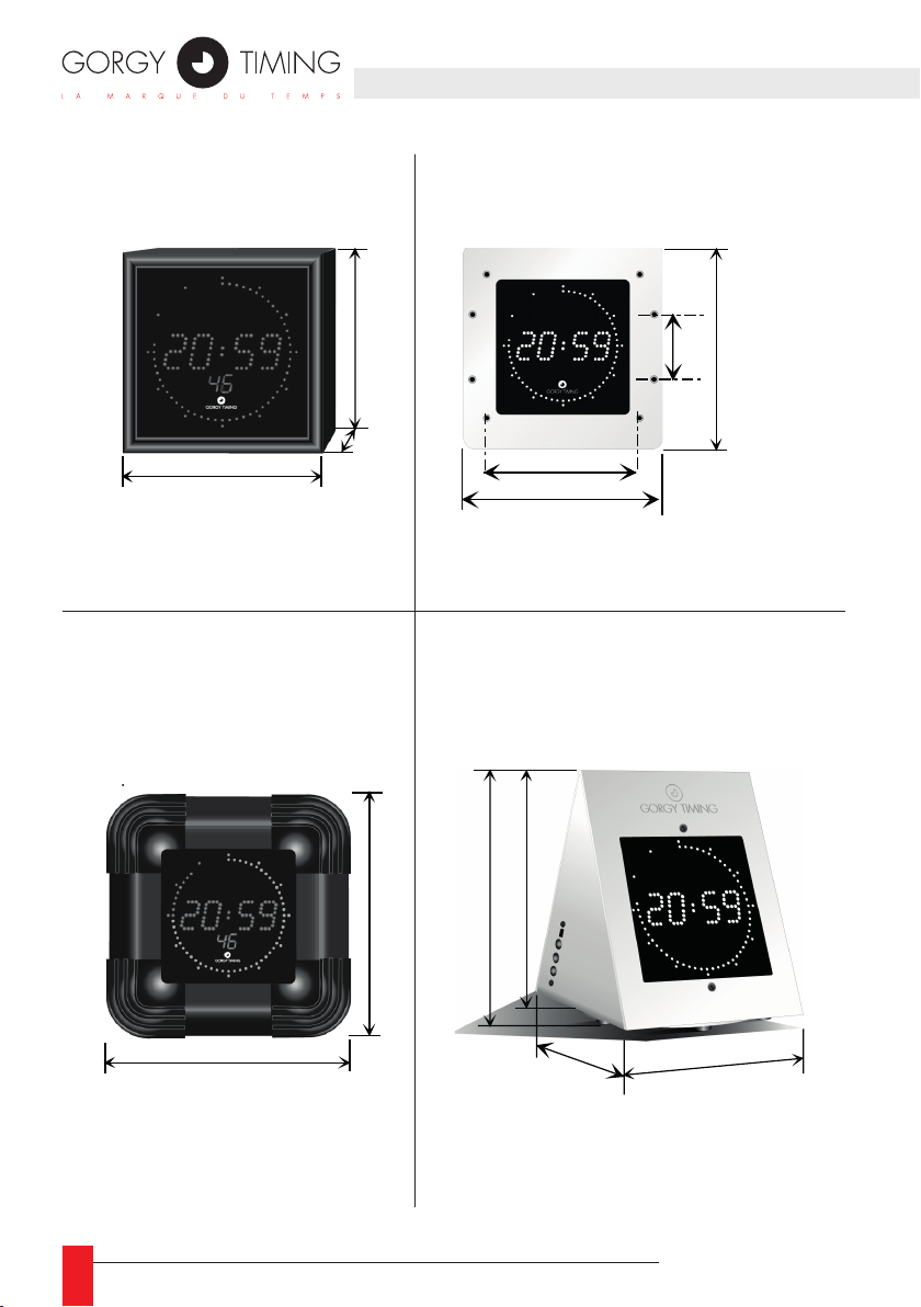
1. CHARACTERISTICS
Boîtier ETANCHE
195
Epaisseur : 120
Boîtier PIVOTANT
Boîtier STANDARD
115
WATERPROOF case
Boîtier ETANCHE
thickness: 120
Epaisseur : 120
115
50
Boîtier ENCASTRABLE
FLUSH-MONTABLE caseSTANDARD case
57
144
160
PIVOTING case
to be placed on a table
à poser sur table
132.5
181
165
OFF
ON
+
-
Prog.
140
130
( cotes : mm)
Dimension in mm
195
195
18
MDE-LEDI160S-1012V1.0
Page 19

► Digital display with Hour, Minute, Second (option “S”), 7 segments with electrolumines-
cent diodes.
► Height of hour and minute numbers: 18mm
► inclination of numbers 10°
► Legibility: to 7 metres
► Supply 230 VAC (+/-10%) 50-60Hz. (via remote transformer)
► Consumption: 6 Watts
► Power reserve of 48 hours with incorporated Ni-Cad battery.
EXISTING VERSIONS:
1.1. STAND-ALONE VERSION
► Incorporated quartz 3.6864Mhz time base, stability +/-0.02 sec/24hrs. between
20°C and 30°C
1.2. PARALLEL MIN. RECEIVING VERSION
► Minute impulse reversed 24V every minute. Impulse duration: 0.1 sec.
► Impulse consumption: 6 mA / 24V
1.3. SERIAL ½ MIN. RECEIVING VERSION
► Serial connection with external 39 Ohm shunt.
► ½ min. impulse reversed every ½ min.
► Impulse duration 0.1 sec.
► Impulse consumption: 1.25 V
► Intensity on line: 60 mA to 120 mA
ENGLISH
1.4. AFNOR NFS 87500 RECEIVING VERSION
► Rated input level: 2.2 VDC
► Input impedance: 3.5 kohms
► Minimum input voltage: 70 mVDC
MDE-LEDI160S-1012V1.0
19
Page 20
2.1. STANDARD CASE
40
127
Wall
opening
Fig.2
127
132.5
57
37.5
144
160
3
Flush-mountable case
103.5
78
65
30
Einhängen
der Uhr
Fig.1
Standardgehäuse
40
127
Wall
opening
Fig.2
127
132.5
57
37.5
144
160
3
Einbaugehäuse
40
127
Wall
opening
Fig.2
127
132.5
57
37.5
144
160
3
Einbaugehäuse
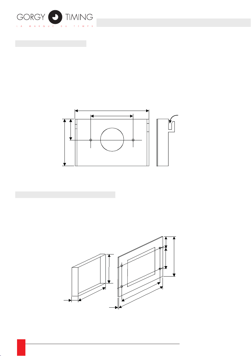
► Preparation of the wall support to x the bracket: allow for a margin of at least
15 mm between the top of the case and the ceiling.
► Fix the bracket to the wall support using two M4 screws.
► Attach the case to the bracket.
Standard case
Fig.1
30
65
2.2. FLUSH-MOUNTABLE CASE
► Preparation of the wall support : provide an opening measuring 127 X 127 mm
► Fix the front to the support using four M4 screws.
Flush-mountable case
Fig.2
40
Wall
opening
127
103.5
78
127
3
Clock attachment
37.5
57
144
160
2. INSTALLATION
132.5
20
MDE-LEDI160S-1012V1.0
Page 21
2.3. WATERPROOF CASE
Case
attachment
2 -
1 - Wire
as shown
27
40
90
108
27
25
Fig.3
Support
to be fixed :
WATERPROOF case
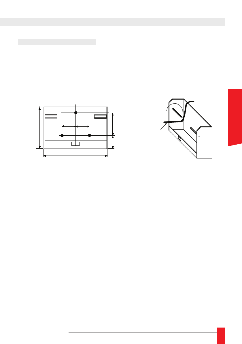
► Preparation and drilling of the wall support.
► Attach the “LEDI” support using three M5 screws.
► Attach and “clip” the clock to its support.
ENGLISH
MDE-LEDI160S-1012V1.0
21
Page 22
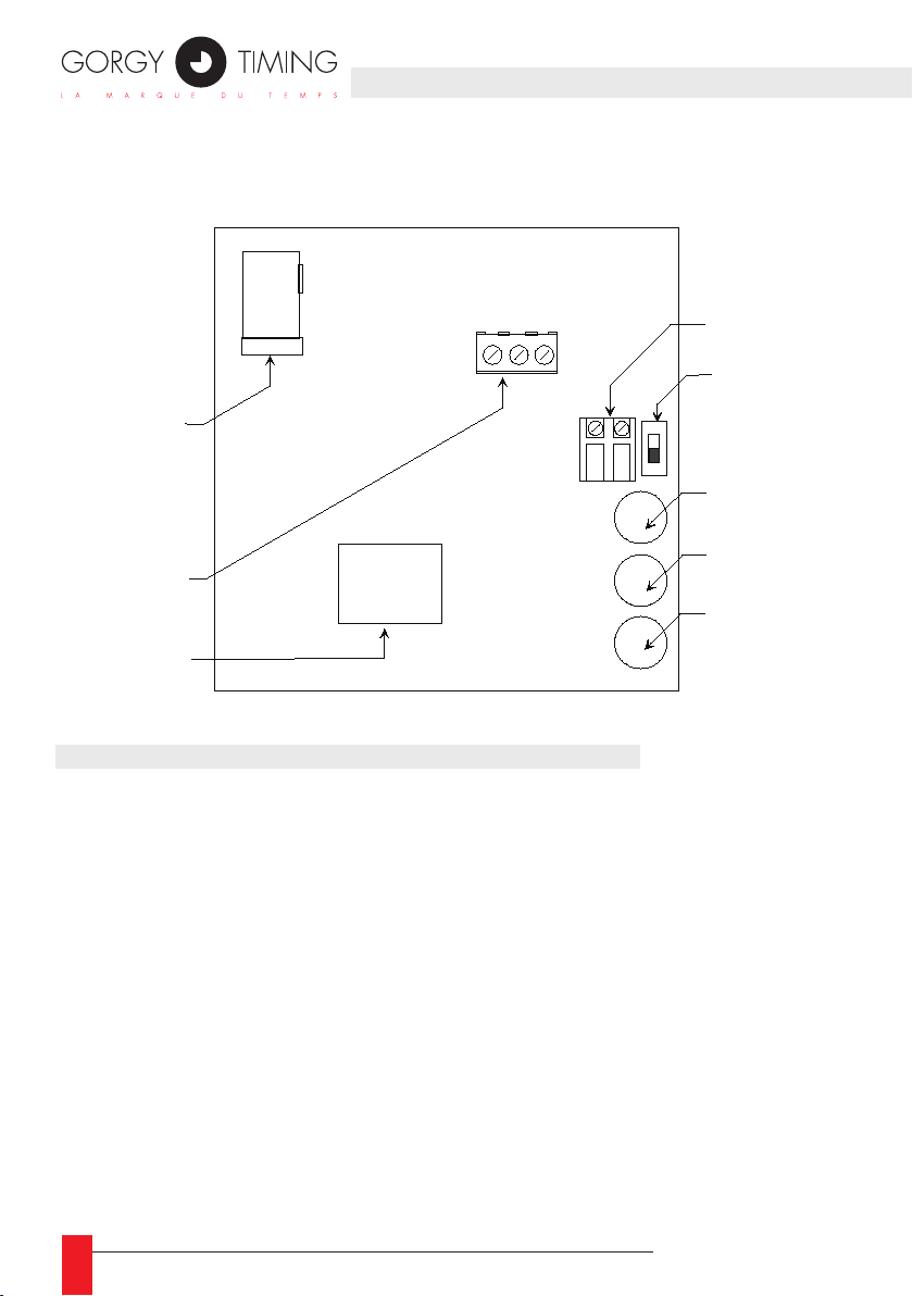
CONNECTIONS
SUPPLY
( B4 )
CHRONOMETER
Input
( B2 )
ASCII
terminal
( B3 )
3 2 1
SYNCHRONISATION
input
( B1 )
Switch
ON/OFF
( SW1 )
" + "
push button
" - "
push button
" PROG "
push button
3. CONNECTIONS
3.1. STANDARD AND FLUSH-MOUNTABLE CASES:
► Connect the 230VAC 50-60Hz supply.
► Switch the battery main switch SW1 to the ON position (lower position).
22
► Connect the synchronisation input to terminal B1, if necessary (no polarity).
► Connect the optional accessories (chronometer - B2, ASCII - B3).
MDE-LEDI160S-1012V1.0
Page 23

3.2. WATERPROOF CASE:
All connections are made to the back of the case without opening it. Perform connections
according to the markings on the wires.
► Connect the 230VAC 50-60Hz supply.
► Connect the synchronisation input and the optional accessories (ASCII input, chro-
nometer, etc.)
☛ Attention: this clock must be a receiver, it cannot stand alone, and it
has no manual luminosity adjustment.
3.3. PIVOTING CASE TO BE PLACED ON A TABLE:
► All connections are made without opening the case. Perform connections according
to the markings on the wires.
► Connect the 230VAC 50-60Hz supply.
► Switch the battery main switch SW1 to the ON position (lower position).
☛ Attention: If clock display remains off, wait a few minutes for the
internal battery to charge.
ENGLISH
MDE-LEDI160S-1012V1.0
23
Page 24
► Setting the time is performed with three buttons, “+”, “– and “PROG”, that are
accessible on the back or on the side (pivoting case).
► With each press on the “PROG” button, a portion of the display begins to blink, and
the blinking portion is modied with the “+” and “– “ buttons (press the button conti-
nuously for faster forward or reverse).
► Setting cycle: 1 Setting the hour
2 Setting the minutes
► Luminosity is adjusted manually with the “+” and “-” buttons, outside of the time
setting cycle.
SYNCHRONISATION:
► If the minutes have not been modied: One press on “PROG” validates the new
programmed time without modifying the initial synchronisation (ex: modication of
the hour/temperature alternation or seasonal time change for stand alone clocks).
► If the minutes have been modied: One press on “PROG” makes the entire display
blink, which indicates that the clock is in synchronisation phase. A second press on
“PROG” makes it possible to synchronise the clock (press this second time at the
same moment as the minute cue provided by a time reference (e.g. the speaking
clock, Tel. No. 3699). The display then stops blinking.
24
MDE-LEDI160S-1012V1.0
Page 25
5. OPTIONS
5.1. TIMER OPTION
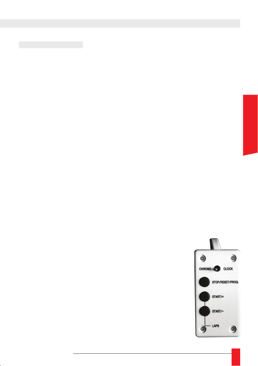
A switch is provided to move from the clock function to the chronometer (timer)function.
There are two possible uses in timer mode:
► Stopwatch
► Count-down
OPERATION :
A set time may be displayed if wished.
5.1.1. Stopwatch function
No set time :
► Press “START/+”. The timer will begin from zero and continue indenitely until the
“STOP” button is pressed.
With set time :
► Press the “PROG” button (this function can only be used when the timer is stop-
ped at zero) and set the required time using the “+” and “-“ buttons (each time the
“PROG” button is pressed, part of the display begins to ash; adjust the hours,
minutes and seconds in succession).
► When programming is completed, press on the “START/+” button. The timer will
begin at the time programmed and continue indenitely until the “STOP” button is
pressed.
ENGLISH
5.1.2. Count-down
No set time :
► Press “START/-”. The timer will begin from zero and continue
for 24 hours or until the “STOP” button is pressed.
With set time :
► Press the “PROG” button (this function can only be used
when the timer is stopped at zero) and set the required time
using the “+” and “-“ buttons (each time the “PROG” button is
pressed, part of the display begins to ash; adjust the hours,
minutes and seconds in succession).
► When programming is completed, press on the “START/-”
button. The timer will begin at the time programmed and stop
automatically at zero, and then redisplay the set time.
MDE-LEDI160S-1012V1.0
25
Page 26
☛ It is also possible to obtain an intermediate time by keeping one of the
1
“LAPS” buttons on the timer pressed.
☛ When a set time is programmed in either stopwatch or count-down
function, the timer may be stopped and restarted at any moment by pressing
on the “STOP” and “ START” buttons, without modifying the set time initially
programmed.
☛ It is possible to trip a dry contact at zero seconds with the pip option
(consult us).
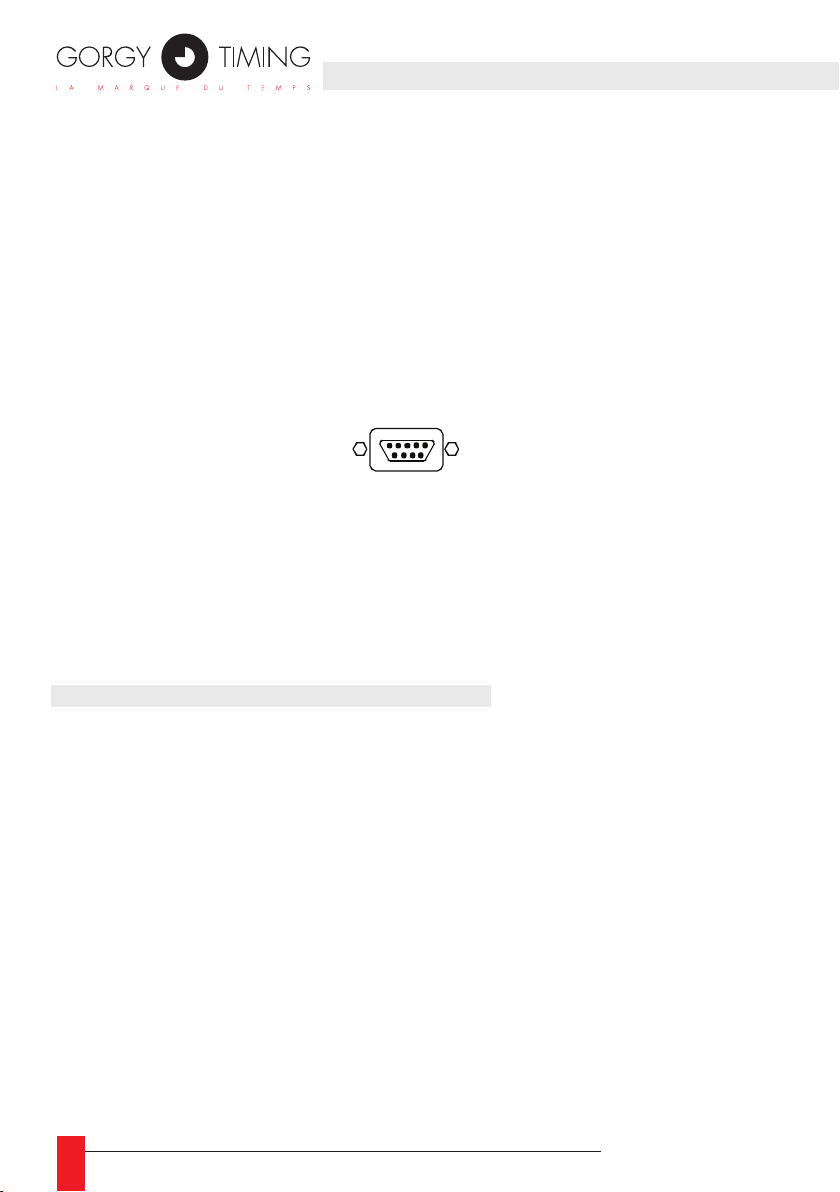
5.1.3. Connection for ush-mountable timer
Timer Sub.D 9 way connector pin out :
► Pin1 : PROG
► Pin2 : +
► Pin3 : -
► Pin4 : Switch clock / chrono
► Pin5 : Gnd
5.2. ASCII RS232 OR RS422/485 OPTIONS
ASCII RS232C link to terminal B3 ASCII RS422/485 link to terminal B3
1: GND 1: E/S 2: TXD 2: E/S +
3: RXD 3: GND
THIS OPTION OPERATES IN 3 MODES
5.2.2. Emission or unidirectional mode
In this mode the clock emits a code (conguration: 2400 bauds, format 8 bits, even
parity, 1 stop bit) in 2 parts:
► 1) – The time information as follows:
STX day of the week SP day of the month/month/year SP SP Hour:minute:second CR
► 2) – The information on the status of the chronometer, temperature, luminosity, etc…
The rst part of this information is used for example to synchronise a computer (in this
case don’t take into account the second part).
The complete information is used to slave another clock to the rst one.
26
MDE-LEDI160S-1012V1.0
Page 27

5.2.2. Receiving mode
In this mode the clock functions autonomously but sets its time according to the ASCII
code received (conguration: 2400 bauds, format 8 bits, even parity, 1 stop bit).
This ASCII code can be:
► 1) – The time information as follows:
STX day of the week SP day of the month/month/year SP SP Hour:minute:second CR
Generated either by the RT3000 or the RADIO TIMING ASCII or any other ASCII
code generator.
► 2) – Or information from another clock of the same type functioning in emission
mode: in this case the rst clock is fully slaved to this second clock.
5.2.3. Bi-directional mode
In this mode the time message coded in ASCII is emitted after the reception of a recognition character (“D”)
(conguration: 2400 bauds, format 8 bits, even parity, 1 stop bit)
► Message emitted:
STX hundredth of a second SP day of the week SP day of the month/month/year SP
SP Hour:minute:second CR
► Ex: 76 FRI 03/02/90 15:14:45, which means that the second corresponding to this
message passed to 76 hundredths of a second at the moment when the character
“ D” was received.
☛ In the case of the LEDI 1/60 (which indicates only hour and minute
information), the date information is replaced with zeros and the day of the
week in alphanumerical characters is replaced by 3 spaces. However, if this
clock is receiving AFNOR NFS 87-500 code or if it is radio-synchronised, the
date information is generated.
☛ In the event of a power outage the display goes off but the clock
continues to function thanks to its internal battery. (the hour cue outputs
and the ASCII output are no longer generated).
☛ For clocks receiving ASCII code, if the message received does not have
the right conguration, manual time setting at start-up may be required. As
soon as the ASCII message has been received, the clock compensates for
any discrepancy with the reference time (this adjustment is impossible with
the waterproof version).
ENGLISH
MDE-LEDI160S-1012V1.0
27
Page 28
GORGY TIMING SAS
Quartier Beauregard
38350 La Mure d'Isère (Grenoble France)
Phone: +33 4 76 30 48 20 Fax: +33 4 76 30 85 33
email: [email protected] - www.gorgy-timing.com
TECHNICAL SUPPORT
+33 476 30 48 20
RADIO TIMING®, LEDI®, LEDICA®, HANDI® are trademarks by GORGY TIMING.
Number of statement for training provider activity : 82 38 04877 38
Gorgy Timing RC74B38 - Any technical, aesthetic, color modications can be made without notice.
28
MDE-LEDI160S-1012V1.0
Page 29
BEDIENUNGSANLEITUNG
LEDI®1.60(S)
DREHBARES TISCHGEHÄUSE
EINBAUGEHÄUSE
STANDARDGEHÄUSE
DEUTSCH
MDE-LEDI160S-1012V1.0
29
Page 30
WICHTIGE SICHERHEITSHINWEISE :
ACHTUNG! Machen Sie sich vor der Installation der Uhr mit dem nachfol-
genden Abschnitt vertraut, und beachten Sie während der Installation die
darin beschriebenen Sicherheitsanweisungen.
Die Vorrichtung der Elektroanlage, an die das Gerät angeschlossen wird,
muss den Anforderungen der Norm NF C 15-100 entsprechen.
Dieses Gerät enthält keinen Schalter für die primäre Stromversorgung. Bei
der Installation der Kabel ist der Einbau einer leicht zugänglichen Unterbrechervorrichtung (Überlastschalter, Trennschalter) erforderlich. Diese Vorrichtung muss die auf dem Gerät angegebenen Nennwerte für Spannung
und Stromstärke unterstützen.
In Europa: im Rahmen vom Schutz von Personen und der Umwelt, ist es in Ihrer
Verantwortung, dieses Gerät in einer Sammelstelle für diesen Zweck (getrennt
vom Hausmüll) zu entsorgen. Für weitere Informationen kontaktieren Sie bitte
Ihren Händler, Sammelstellen oder lokalen Behörden.
Jede Änderung oder Öffnung des Produkts ohne Zustimmung führt zum Verlust
der Garantie.
Alle Wartungsarbeiten müssen spannungslos durchgeführt werden, einschließlich
der daran angeschlossenen Geräte.
Allgemein sollten sich die Stromkabel (220 VAC) und Datenkabel nicht berühren
um Störungen zu vermeiden. (Mindestabstand ein paar Zentimer).
Gorgy Timing lehnt jegliche Verantwortung ab für Unfälle oder Schäden die
durch unsachgemäße Anwendung des Produktes verursacht wurden.
Die Produkte von GORGY TIMING entsprechen folgenden Normen:
CE, EN 60950, EN 55022, EN 50024
30
MDE-LEDI160S-1012V1.0
Page 31

INHALTSVERZEICHNIS
1. BESCHREIBUNG ........................................................................................................ 32
1.1. Autonome Quarzuhr ........................................................................................................... 33
1.2. Nebenuhr mit polwechselnden Minutenimpulsen, parallel ................................................. 33
1.3. Nebenuhr mit seriellen ½ Minutenimpulsen ...................................................................... 33
1.4. Nebenuhr mit AFNOR NFS 87500 ..................................................................................... 33
2. BEFESTIGUNG ............................................................................................................ 34
2.1. Standardgehäuse ............................................................................................................... 34
2.2. Einbaugehäuse ................................................................................................................... 34
2.3. Außengehäuse (siehe Abb.3) ............................................................................................. 35
3. ANSCHLÜSSE ............................................................................................................. 36
3.1. Standard- und Einbaugehäuse ........................................................................................... 36
3.2 Wetterfestes Gehäuse ......................................................................................................... 37
3.3. Drehbares Tischgehäuse .................................................................................................... 37
4. ZEITEINSTELLUNG .................................................................................................... 38
5. OPTIONEN ................................................................................................................... 39
5.1. GEBRAUCHSANLEITUNG OPTION CHRONO ................................................................ 39
5.1.1. Arbeitsweise als Stoppuhr mit Aufwärtszählung: .................................................... 39
5.1.2. Arbeitsweise als Stoppuhr mit Abwärtszählung: ..................................................... 39
5.1.3. Anschluss der Modelle Standard und Einbaugehäuse ........................................... 40
5.2. OPTION ASCII RS232 oder RS422/485 ............................................................................ 40
5.2.1. Unidirektionaler Modus ........................................................................................... 40
5.2.2. Modus Empfänger ................................................................................................. 41
5.2.3. Bi-direktionaler Modus ............................................................................................ 41
MDE-LEDI160S-1012V1.0
31
DEUTSCH
Page 32
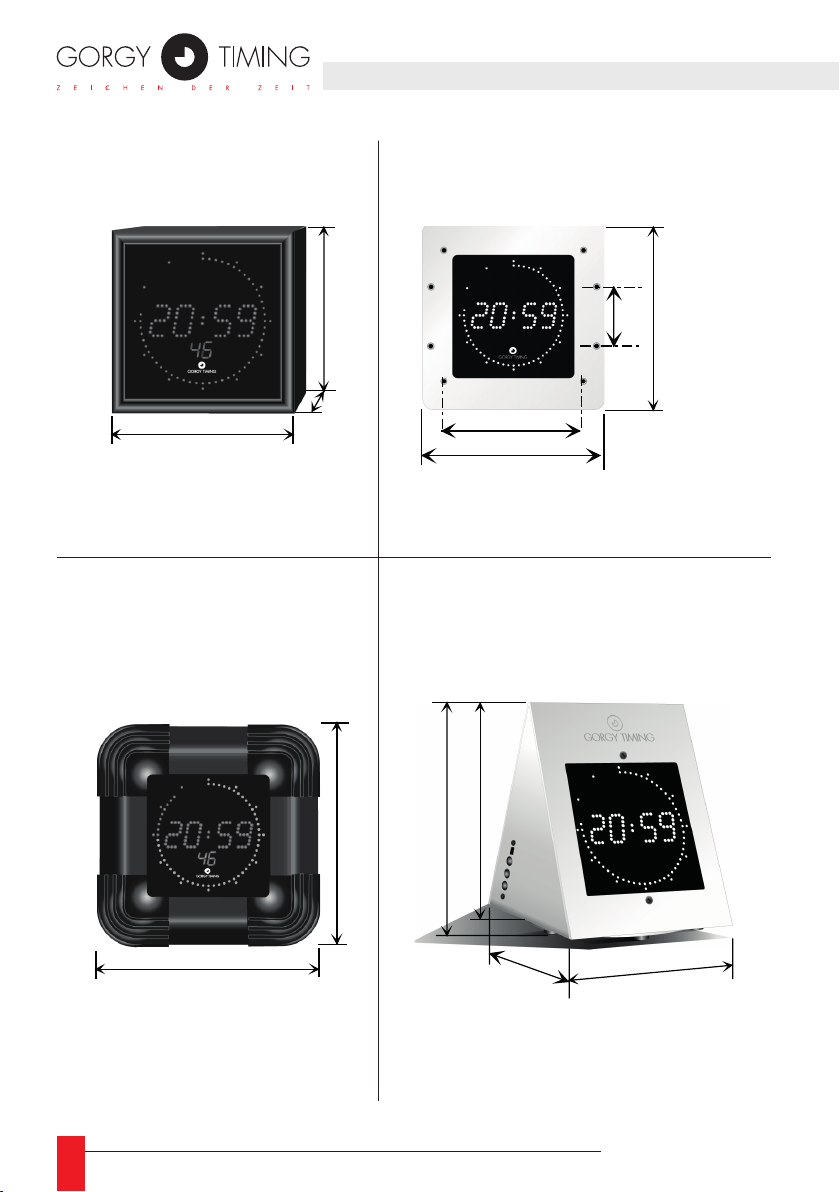
1. BESCHREIBUNG
Boîtier ETANCHE
195
Epaisseur : 120
Boîtier PIVOTANT
Boîtier STANDARD
115
Außengehäuse
Boîtier ETANCHE
Tiefe : 120
Epaisseur : 120
115
50
Boîtier ENCASTRABLE
EinbaugehäuseStandardgehäuse
57
144
160
Drehbares Tischgehäuse
à poser sur table
132.5
181
165
OFF
ON
+
-
Prog.
140
(Maße in mm)
130
( cotes : mm)
195
195
32
MDE-LEDI160S-1012V1.0
Page 33

► Digitale 7-Segment-Anzeige mit Leuchtdioden: Stunde, Minute (Sekunde: Option « S »)
Sekunde: Diodenkreis von 60 LED, Ø 8 cm
► Höhe der Stunden- und Minutenziffern: 20 mm
► Neigungswinkel der Ziffern: 10°
► Ablesbarkeit: 7 Meter
► Netzanschluss 230 VAC (+/-10%) 50-60 Hz. (abgesetztes Netzteil)
► Verbrauch: 6 Watt
► Datenspeicherung bei Netzausfall: mindestens 2 Tage durch eingebauten Ni-Mh-Akku
AUSFÜHRUNGEN :
1.1. AUTONOME QUARZUHR
► Zeitbasis mit eingebautem Quarz 3.6864 MHz, Stabilität +/-0.02 Sek./24h zwischen
20 °C und 30 °C
1.2. NEBENUHR MIT POLWECHSELNDEN MINUTENIMPULSEN, PARALLEL
► Polwechselnder Impuls 24 V jede Minute. Impulsdauer: 0.1 Sek.
► Impulsverbrauch: 6 mA / 24 V
1.3. NEBENUHR MIT SERIELLEN ½ MINUTENIMPULSEN
► Serieller Anschluss mit externem Shunt von 39 Ohm.
► Polwechselnder Impuls jede halbe Minute.
► Impulsdauer: 0.1 Sek.
► Impulsverbrauch: 1.25 V
► Belastbarkeit der Linie: 60 mA bis 120 mA.
DEUTSCH
1.4. NEBENUHR MIT AFNOR NFS 87500
► Nennspannung 2.2 V Spitze/Spitze
► Impedanz am Eingang: 3.5 kOhm
► Mindestspannung am Eingang: 70 mV Spitze/Spitze
MDE-LEDI160S-1012V1.0
33
Page 34
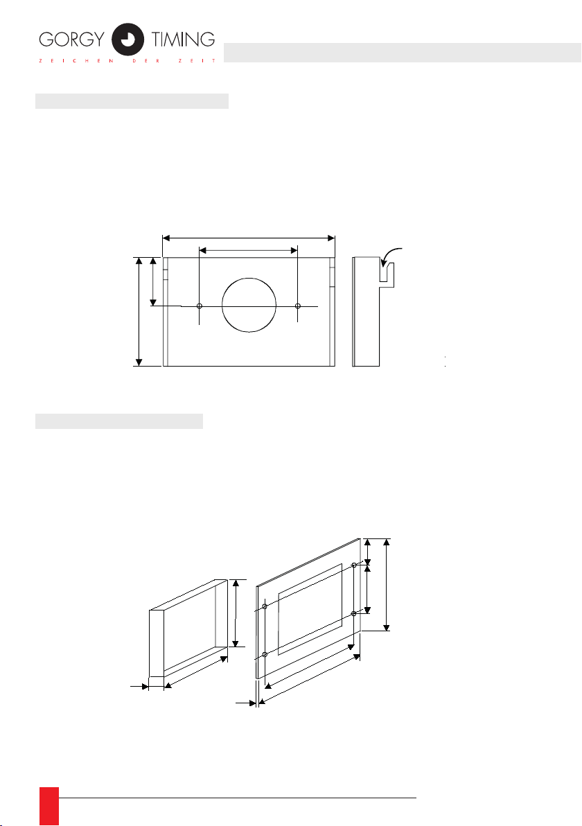
2. BEFESTIGUNG
Standardgehäuse
40
127
Wall
opening
Fig.2
127
132.5
57
37.5
144
160
3
Einbaugehäuse
2.1. STANDARDGEHÄUSE
► Platz für die Halterung so planen, dass ein Mindestabstand des Gehäuses von
15 mm zur Decke eingehalten wird.
► Halterung mit zwei Schrauben M4 an der Wand befestigen.
► Gehäuse in die Halterung einhängen.
65
2.2. EINBAUGEHÄUSE
► Wandöffnung vorbereiten: Öffnung 127 X 127 mm
► Einbaurahmen montieren.
► Vorderseite mit vier Schrauben M4 befestigen.
Fig.1
30
Einbaugehäuse
Fig.2
Wall
opening
40
127
103.5
78
127
3
144
160
Einhängen
der Uhr
37.5
57
132.5
34
MDE-LEDI160S-1012V1.0
Page 35
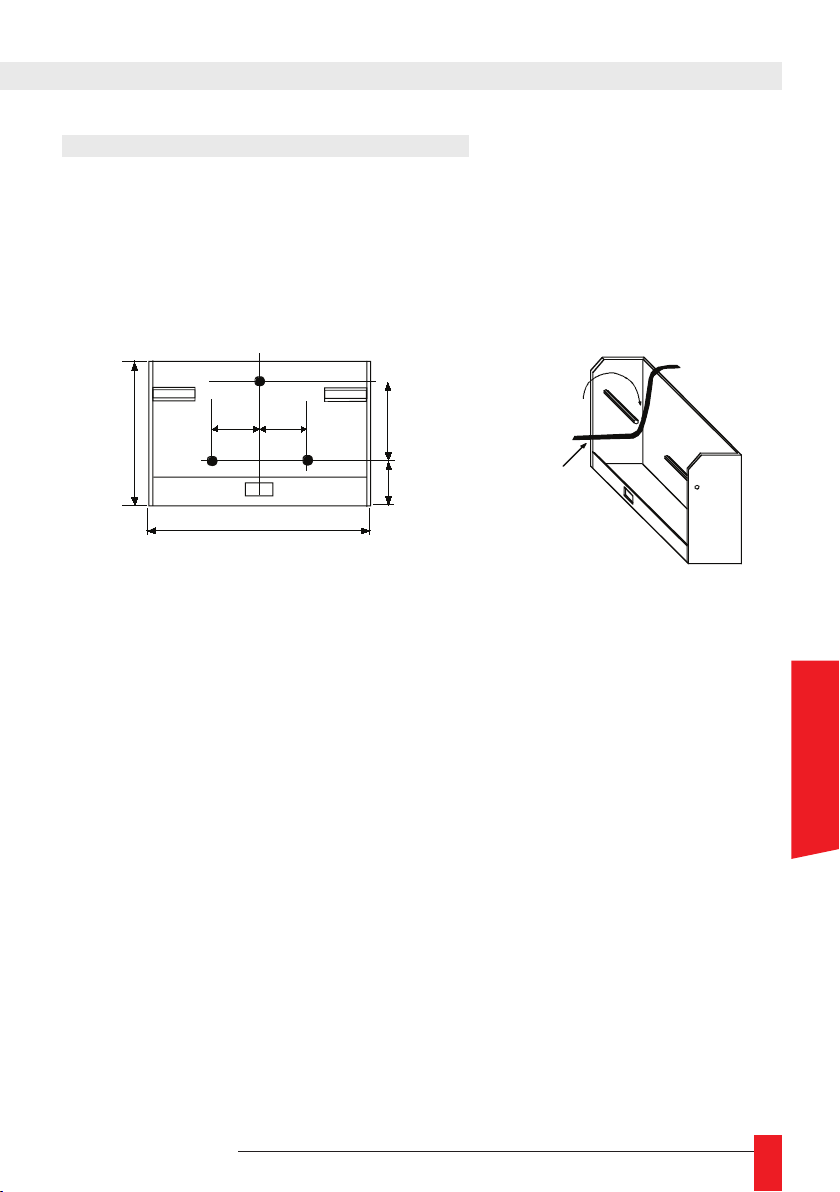
2.3. AUSSENGEHÄUSE (SIEHE ABB.3)
Anbringen
des Gehäuses
2 -
1 - Kabel
folgendermaßen
einführen
27
40
90
108
27
25
Abb.3
Halterung :
Außengehäuse
► Vorbereiten und Bohrungen setzen für die Halterung.
► Die Halterung mit 3 Schrauben M5 befestigen.
► Die Uhr in die Halterung einrasten.
MDE-LEDI160S-1012V1.0
DEUTSCH
35
Page 36
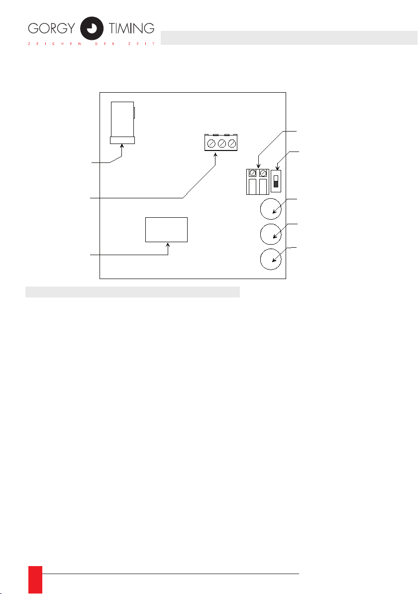
3.1. STANDARD- UND EINBAUGEHÄUSE
Netzspannung
( B4 )
Eingang
STOPPUHR
( B2 )
Klemme
ASCII
( B3 )
3 2 1
Eingang für die
SYNCHRONISATION
( B1 )
Schalter
ON/OFF
( SW1 )
Taste
" + "
Taste
" - "
Taste
" PROG "
► Stromversorgung 230 VAC 50-60 Hz anschließen.
3. ANSCHLÜSSE
36
► Den Batterieschalter SW1 nach Verkabelung unter Spannung auf ON schieben
(nach unten).
► Synchronisationseingang, wenn vorhanden mit der Klemme B1 verbinden (keine
Polarität.).
► Optionen anschließen (Stoppuhr an B2, ASCII an B3).
MDE-LEDI160S-1012V1.0
Page 37

3.2 WETTERFESTES GEHÄUSE
Alle Anschlüsse sind auf der Rückseite, das Gehäuse muss nicht geöffnet werden.
► Stromversorgung anschließen 230 VAC 50-60 Hz.
► Synchronisationseingang anschließen, danach die Optionen (Eingang ASCII, Stop-
puhr…)
☛ Bemerkung: Diese Uhr gibt es ausschließlich als Nebenuhr ohne
manuelle Helligkeitsregelung.
3.3. DREHBARES TISCHGEHÄUSE
► Das Gehäuse muss nicht geöffnet werden. Kabel der Markierung entsprechend
anschließen.
► Stromversorgung 230 VAC 50-60 Hz anschließen.
► Anschließend den Batterieschalter SW1 auf ON schieben (nach unten).
☛ Bemerkung: Wenn die Anzeige nicht aueuchtet, einige Minuten warten,
bis sich der interne Akku etwas aufgeladen hat.
MDE-LEDI160S-1012V1.0
DEUTSCH
37
Page 38
4. ZEITEINSTELLUNG
► Die Uhr wird mit den drei Tasten „+ „, „ –“ und „ PROG „ eingestellt, die sich an der
Rückseite oder (beim drehbaren Tischgehäuse) der Seitenäche der Uhr benden.
► Jeder Druck auf die Taste « PROG » bringt einen bestimmten Teil der Anzeige zum
Blinken. Die blinkenden Ziffern können mit den Tasten „+ „ und „ – „ verändert werden.
(Dauerdruck auf die entsprechende Taste lässt die Anzeige schnell durchlaufen)
► Reihenfolge der Einstellungen: 1 Stunden
2 Minuten
► Die Helligkeitsregelung erfolgt manuell mit den Tasten „+“ und „-“ außerhalb des
Modus Zeiteinstellung.
SYNCHRONISATION :
► Wurde die Minutenanzeige nicht verändert, bewirkt ein Druck auf die Taste
„PRO“ die Programmierung der neu eingestellten Uhrzeit, ohne die ursprüngliche
Synchronisation zu verändern (z. B.: bei Änderung der Dauer des Wechsels Uhrzeit/
Temperatur oder bei Umstellung von Sommer- und Winterzeit bei einer autonomen
Uhr)
► Wurden die Minuten verändert, lässt ein Druck auf die Taste „PROG“ die ganze
Anzeige blinken und zeigt an, dass die Uhr bereit ist zur Synchronisation. Durch
einen zweiten Druck auf die Taste „PROG“ beim exakten Zeitzeichen einer
Referenzuhr (z. B. Rundfunkgerät) wird die Uhr neu synchronisiert. Die Anzeige
blinkt nicht mehr.
38
MDE-LEDI160S-1012V1.0
Page 39

5. OPTIONEN
5.1. GEBRAUCHSANLEITUNG OPTION CHRONO
► Der «clock/chrono» Schalter wechselt von einer Funktion zur anderen. Inder Position
«clock» wird die Zeit angezeigt, bei «chrono» ist die Stoppuhrfunktion aktiviert.
► Es gibt zwei Möglichkeiten der Zeitnahme:
► Aufwärtszählung (+)
► Abwärtszählung (-)
Es besteht die Möglichkeit einer Zeitvorwahl.
5.1.1. Arbeitsweise als Stoppuhr mit Aufwärtszählung:
► ohne Zeitvorwahl:
«START/+» (Aufwärtszählung) drücken. Die Stoppuhr beginnt ab Null zu
zählen bis zum nächsten Druck auf die Taste «STOPP».
► mit Zeitvorwahl:
Für diese Funktion muss die Stoppuhr angehalten und auf Null zurückgestellt sein
(Taste «STOPP»). Durch Druck auf die Taste «PROG» den Teil der Anzeige zum
Blinken bringen, der programmiert werden soll (in der Reihenfolge: Stunden, Minuten, Sekunden). Dann mit den Tasten «+» und «-» die gewünschte Zeit einstellen.
Ist alles eingestellt, nochmals die Taste «PROG» drücken.
Durch Betätigen der Taste «START/+» wird die Stoppuhr von der programmiertenZeit an aufwärts zählen bis zum nächsten Druck auf die Taste «STOPP».
5.1.2. Arbeitsweise als Stoppuhr mit Abwärtszählung:
► ohne Zeitvorwahl:
«START/-» (Abwärtszählung) drücken. Die Stoppuhr beginnt ab Null, 24 Stunden
lang oder bis zum nächsten Druck auf die Taste «STOPP» abwärts zu zählen.
► mit Zeitvorwahl:
Für diese Funktion muss die Stoppuhr angehalten und auf Null zurückgestellt sein
(Taste «STOPP»). Durch Druck auf die Taste «PROG» den Teil der Anzeige zum
Blinken bringen, der programmiert werden soll (in der Reihenfolge: Stunden, Minuten, Sekunden). Dann mit den Tasten «+» und «-» die gewünschte Zeit einstellen.
Ist alles eingestellt, nochmals die Taste «PROG» drücken.
Durch Betätigen der Taste «START/-» wird die Stoppuhr von der programmierten
Zeit abwärts zählen bis Null, und anschließend wieder die programmierte Zeit an-
zeigen.
☛ Zum Ablesen von Zwischenzeiten hält man eine der Tasten (LAPS)
gedrückt.
MDE-LEDI160S-1012V1.0
DEUTSCH
39
Page 40

☛ Ist eine bestimmte Zeit auf- oder abwärts programmiert, können
1
Zwischenzeiten genommen werden durch Drücken der Tasten «START»,
dann «STOP», ohne die ursprünglich programmierte Zeit zu verändern.
☛ Die Option Zeitzeichen bietet die Möglichkeit, bei Erreichen der
Sekunde Null, einen Ausgang zu aktivieren. (Bitte bei uns anfragen!)
5.1.3. Anschluss der Modelle Standard und Einbaugehäuse
SUBD9 Anschluss (Verkabelung der Stoppuhrsteuerung):
► Pin1 : PROG
► Pin2 : +
► Pin3 : -
► Pin4 : Schalter Uhr/Stoppuhr
► Pin5 : Erde
5.2. OPTION ASCII RS232 ODER RS422/485
Belegung der Klemmen
Anschluss ASCII RS232C an der Klemme B3 Anschluss ASCII RS422/485 an der Klemme B3
1 : GND 1 : E/S 2 : TXD 2 : E/S +
3 : RXD 3 : GND
Es gibt drei verschiedene Anwendungsmöglichkeiten:
5.2.1. Unidirektionaler Modus
Die Uhr sendet einen zweiteiligen Code (Konguration: 2400 Baud, Format 8 Bit, gerade Parität, 1 Stoppbit):
► 1) Die Zeitinformation in folgendem Format:
STX Wochentag SP Monatstag/Monat/Jahr SP SP Stunde:Minute:Sekunde CR
► 2) Die Informationen der Zustände Stoppuhr, Temperatur, Helligkeit usw. ...
Der erste Teil der Information dient z. B. zum Synchronisieren eines Computers. (In
diesem Fall wird der zweite Teil der Information nicht beachtet.)
Die komplette Information dient zum Anschluss einer zweiten Uhr an die erste.
40
MDE-LEDI160S-1012V1.0
Page 41

5.2.2. Modus Empfänger
In diesem Modus ist die Uhr eine autonome Uhr. Die Zeitübertragung erfolgt aber durch
Übernahme des empfangenen ASCII-Codes (Konguration: 2400 Baud, Format 8 Bit,
gerade Parität, 1 Stoppbit).
Der Code kann sein:
► 1) eine Zeitinformation in der Art:
STX Wochentag SP Monatstag/Monat/Jahr SP SP Stunde:Minute:Sekunde CR.
Die Information kann von einer RT3000, einer RADIO TIMING ASCII oder irgendei-
nem anderen ASCII-Code-Generator geliefert werden.
► 2) die Zeitinformation einer Uhr des gleichen Typs im Modus Sender.
In diesem Fall zeigt die Uhr dieselbe Information wie die sendende Uhr an.
5.2.3. Bi-direktionaler Modus
In diesem Modus wird das Zeittelegramm des ASCII-Codes erst übertragen nach Empfang eines Erkennungszeichens (Zeichen „D“).
(Konguration: 2400 Baud, Format 8 Bit, gerade Parität, 1 Stoppbit)
► Format der Zeitinformation:
STX Wochentag SP Monatstag/Monat/Jahr SP SP Stunde:Minute:Sekunde CR
Beispiel: 76 Mit 03/02/90 15:14:45 bedeutet, dass bei Empfang des Zeichens „D“
die zum Telegramm gehörende Sekunde zu 76/100 vergangen ist.
☛ Bei einer LEDI 1/60 (sie zeigt nur die Stunde, Minute und Sekunde an)
wird die Datumsinformation durch Nullen ersetzt und der digitale Wochentag
durch drei Leerzeichen. Wenn die Uhr eine Nebenuhr mit Code AFNOR
NFS 87-500 oder eine funkgeführte Uhr ist, wird die Datumsinformation
trotzdem bereitgestellt und könnte über einen entsprechenden Ausgang
weitergegeben werden.
☛ Bei Stromausfall erlischt die Anzeige. Die Uhr läuft über ihren internen
Akku weiter. (Die Zeitzeichen und der Ausgang Code ASCII werden nicht
☛ Wenn bei Nebenuhren mit Code ASCII das Zeittelegramm fehlerhaft
ist, kann eine manuelle Zeiteinstellung notwendig werden. Sobald das
Zeittelegramm wieder korrekt empfangen wird, korrigiert die Uhr eventuelle
Differenzen automatisch. (Bei einer Außenuhr ist die manuelle Einstellung
MDE-LEDI160S-1012V1.0
mehr generiert.)
nicht möglich.)
DEUTSCH
41
Page 42
GORGY TIMING GMBH
Östliche Rheinbrückenstr. 50
D-76187 Karlsruhe - DEUTSCHLAND
Tél : +49 721 60156
Fax : +49 721 695259
www.gorgy-timing.de
TECHNICHER SUPPORT
+33 476 30 48 20
RADIO TIMING®, LEDI®, LEDICA®, HANDI® Marke und Modelle geschützt GORGY TIMING.
GORGY TIMING RC 74 B 38 - Änderungen der Technik und Gestaltung vorbehalten
Numéro de déclaration d’activité de prestataire de formation : 82 38 04877 38
42
MDE-LEDI160S-1012V1.0
Page 43
2. INSTALLATIONNOTES
MDE-LEDI160S-1012V1.0
43
Page 44

www.gorgy-timing.com
RADIO TIMING®, LEDI®, LEDICA®, HANDI® sont des marques déposées GORGY TIMING.
Numéro de déclaration d’activité de prestataire de formation : 82 38 04877 38
GORGY TIMING RC 74 B 38 - Toutes modications d'ordre technique ou esthétique peuvent être apportées sans préavis.
RADIO TIMING®, LEDI®, LEDICA®, HANDI® are trademarks by GORGY TIMING.
GORGY TIMING RC 74 B 38 - Any technical, aesthetic, color modications can be made without notice.
RADIO TIMING®, LEDI®, LEDICA®, HANDI® sont marcas registradas GORGY TIMING.
GORGY TIMING RC 74 B 38 - Cualquier modicación de orden técnico, estético o de color pueden realizarse sin previo aviso.
RADIO TIMING®, LEDI®, LEDICA®, HANDI® Marke und Modelle geschützt GORGY TIMING.
GORGY TIMING RC 74 B 38 - Änderungen der Technik und Gestaltung vorbehalten
44
MDE-LEDI160S-1012V1.0
 Loading...