

Gorenje TGR 50-100 XNGU Instructions For Use Manual
TGR 50-100 XNGU

2
3
Instructions for Use 4
EN
Upute za upotrebu 9
Uputstva za upotrebu 14
HR
BIH
SR
Udhëzime për përdorim 19
SQ
Упaтства за употребa 25
MK

4
EN
WARNINGS
The appliance may be used by children older than 8 years old, elderly
persons and persons with physical, sensory or mental disabilities or lacking
experience and knowledge, if they are under supervision or taught about safe
use of the appliance and if they are aware of the potential dangers.
Children should not play with the appliance.
Children should not clean or perform maintenance on the appliance
without supervision.
Installation should be carried out in accordance with the valid regulations
and according to the instructions of the manufacturer and by qualified staff.
In a closed, pressurised system of installation, it is obligatory to install a
safety valve on the inlet pipe with a rated pressure of 0.6 MPa (6 bar), 0.9 MPa
(9 bar) or 1.0 MPa (10 bar) (see the label), which prevents the elevation of
pressure in the boiler by more than 0.1 MPa (1 bar) above the rated pressure.
Water may drip from the outlet opening of the safety valve, so the outlet
opening should be set to atmospheric pressure.
The outlet of the safety valve should be installed facing downwards and in
a non-freezing area.
To ensure proper functioning of the safety valve, the user should perform
regular controls to remove limescale and make sure the safety valve is not
blocked.
Do not install a stop valve between the water heater and the safety valve,
because it will impair the pressure protection of the heater!
Before connecting it to the power supply, the water heater must be filled
with water!
The heater is equipped with an additional thermal cut-off for protection in
case of failure of the operating thermostat. In this case, however, the
temperature of the water in the heater can reach up to 130 °C according to the
safety standards. During the water supply installation, the possibility of
temperature overloads should be taken into account.
If the heater is to be disconnected from the power supply, please drain any
water from the heater to prevent freezing.
Please do not try to fix any defects of the water heater on your own. Call
the nearest authorised service provider.
Our products incorporate components that are both environmentally
safe and harmless to health, so they can be disassembled as easily as
possible and recycled once they reach their final life stage.
Recycling of materials reduces the quantity of waste and the need for
production of raw materials (e.g. metals) which requires a substantial
amount of energy and causes release of harmful substances. Recycling
procedures reduce the consumption of natural resources, as the waste parts
made of plastic and metal can be returned to various production processes.
For more information on waste disposal, please visit your waste collection
centre or the store where the product was purchased.
EN
5
Dear buyer, thank you for purchasing our product.
Prior to the installation and first use of the electric water heater, please read
these instructions carefully.
This water heater has been manufactured in compliance with the relevant standards
and tested by the relevant authorities as indicated by the Safety Certificate and the
Electromagnetic Compatibility Certificate. The technical characteristics of the product
are listed on the label affixed between the inlet and outlet pipes. The installation must
be carried out by qualified staff. All repairs and maintenance work within the water
heater, e.g. lime removal, must be carried out by an authorised maintenance service
provider.
INSTALLATION
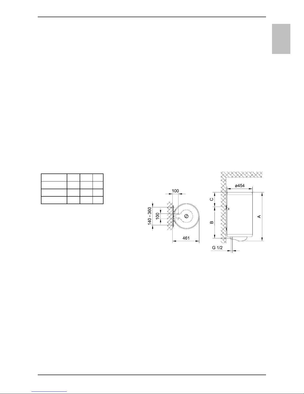
The water heater shall be installed as close as possible to the outlets. When installing
the water heater in a room with a bathtub or shower, take into account the
requirements defined in IEC Standard 60364-7-701 (VDE 0100, Part 701). It has to
be fitted to the wall using appropriate wall screws with a minimum diameter of 8 mm.
A wall with a poor load-bearing capacity must be properly reinforced where the heater
will be installed. The water heater may only be fixed upon the wall vertically.
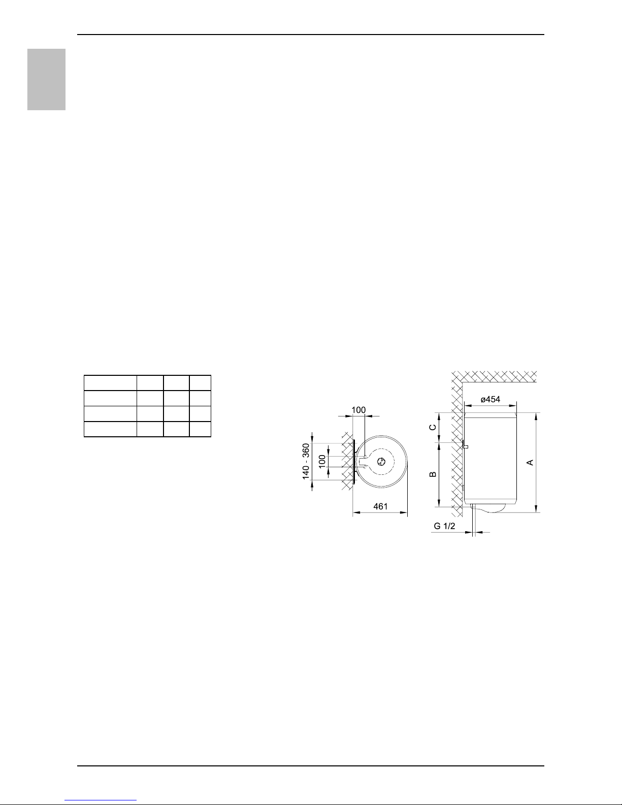
Connection and installation
dimensions of the water heater [mm]
CONNECTION TO THE WATER SUPPLY
The water heater connections for the inlet and outlet of water are colour-coded. The
inlet of cold water is marked with blue colour, while the hot water outlet is marked
with red colour.
The water heater can be connected to the water supply in two ways. The closed-
circuit pressure system enables several points of use, while the open-circuit gravity
system enables a single point of use only. The mixer taps must also be installed in
accordance with the selected installation mode.
The open-circuit gravity system requires the installation of a non-return valve in order
to prevent the water from draining out of the tank in the event of the water supply
running dry or being shut down. This installation mode requires the use of a crossflow mixer tap. As the heating of water expands its volume, this causes the tap to
drip. The dripping cannot be stopped by tightening it further; on the contrary, the
A B C
TGR 50 X 570 405 145
TGR 80 X 775 605 150
TGR 100 X 935 755 160
6
EN
tightening can only damage the tap.
The closed-circuit pressure system requires the use of pressure mixer taps. For
safety reasons the supply pipe must be fitted with a safety valve or alternatively, a
valve of the safety class that prevents the pressure in the tank from exceeding the
nominal pressure by more than 0.1 MPa (1 bar). The outlet opening on the relief
valve must be equipped with an outlet for atmospheric pressure.
The heating of water in the heater causes the pressure in the tank to increase to the
level set by the safety valve. As the water cannot return to the water supply system,
this can result in dripping from the outlet of the safety valve. The drip can be piped to
the drain by installing a catching unit just below the safety valve. The drain installed
below the safety valve outlet must be piped down vertically and placed in an
environment that is free from the onset of freezing conditions.
In case the existing plumbing does not enable you to pipe the dripping water from the
safety valve into the drain, you can avoid the dripping by installing a 3-litre expansion
tank on the inlet water pipe of the boiler.
In order to provide correct operation of the safety valve, periodical inspections of the
relief valve must be carried out by the user to eliminate any limescale and check if the
safety valve is blocked. To check the valve, open the outlet of the safety valve by
turning the handle or unscrewing the nut of the valve (depending on the type of the
valve). The valve is operating properly if the water comes out of the nozzle when the
outlet is open.
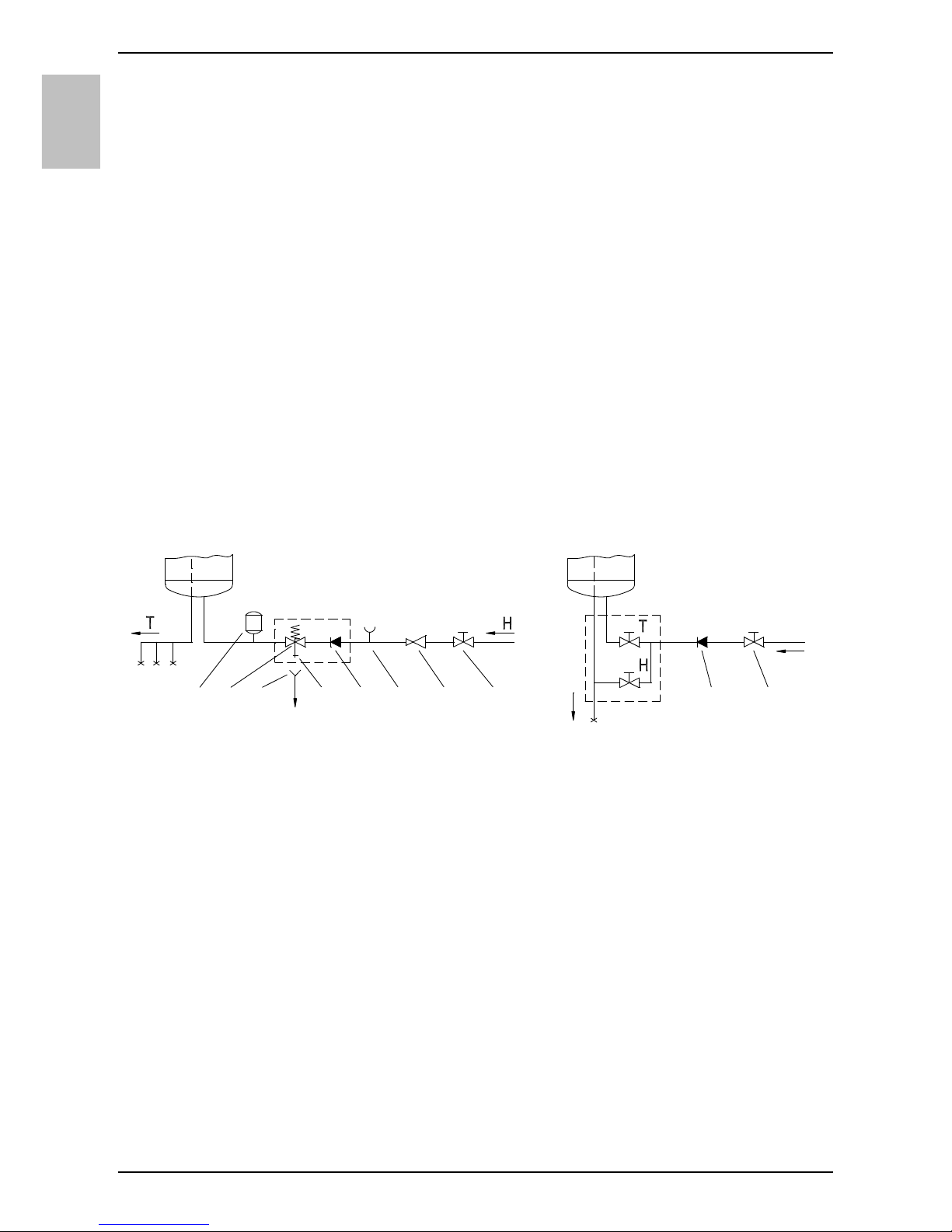
Closed (pressure) system Open (non-pressure) system
Between the water heater and safety valve, no closing valve may be built in
because it could impede the function of the safety valve.
The heater can be connected to the domestic water supply network without a
pressure-reducing valve if the pressure in the network is lower than the nominal
pressure. If the pressure in the network exceeds the nominal pressure, a pressurereducing valve must be installed.
Before connecting it to the power supply, the water heater must be filled with
water. When filling the heater for the first time, the tap for the hot water on the
mixing tap must be opened. When the heater is filled with water, the water starts to
run through the outlet pipe of the mixing tap.
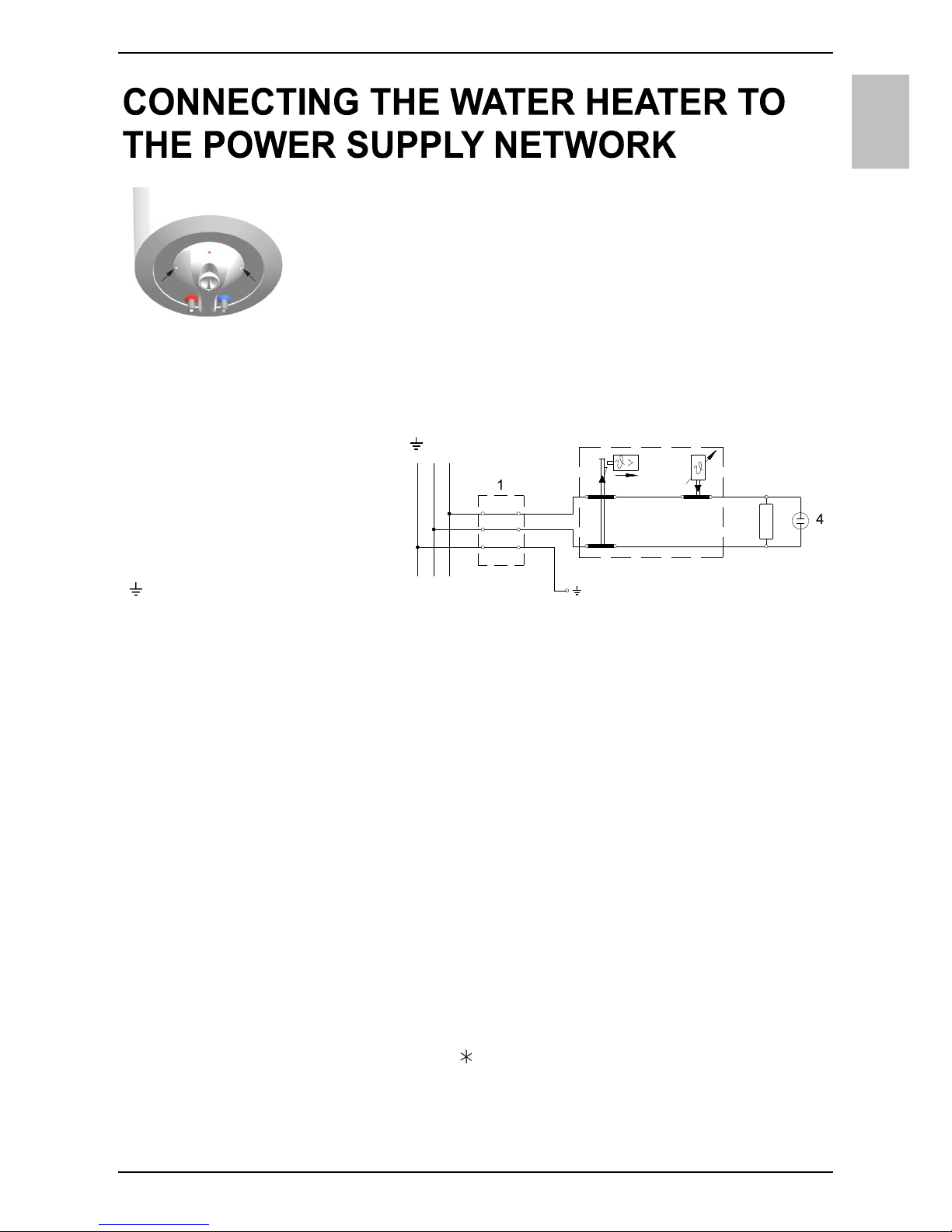
1 7 53546328
Legend:
1 - Safety valve
2 - Test valve
3 - Non-return valve
4 - Pressure reduction valve
5 - Closing valve
6 - Checking fitting
7 - Funnel with outlet connection
8 - Expansion tank
H - Cold water
T - Hot water
EN
7
Before connecting to the power supply network, install a power
supply cord in the water heater, with a min. diameter of 1.5 mm2
(H05VV-F 3G 1.5 mm2). To do this, the protective cap must be
removed from the water heater.
Connecting the heater to the power supply network must take
place in accordance with the standards for electric appliances.
To comply with the national installation regulations, an all poles
disconnect switch must be installed between the water heater and the power supply
network.
CAUTION: Before any intervention into the interior of the water heater,
disconnect it from the power supply network!
OPERATION AND MAINTENANCE
After connecting to the water and power supply, the heater is ready for use. By
turning the thermostat knob, water temperature can be set between 10 °C and 65 °C
+5 °C/-0 °C. We recommend that the knob be set to the position "eco" ensuring the
most economic operation of the water heater. This way, the water temperature is
maintained at 55 °C while the operation also results in less lime sediment as well as
in less heat losses than is the case at higher temperatures. During the operation of
an electric heater can hear noise in the water heater. The light indicator shows the
operation of the heating element. On the casing of the water heater a bimetal
thermometer is mounted, pointing clockwise (to the right) whenever there is hot water
in the water heater. The thermometer shows the temperature at the place of
installation, while the control knob on the thermostat sets the temperature of water in
the bottom part of the heater. As a result these two temperatures may differ. When
the water heater is not in use for longer periods of time, it should be protected from
freezing by setting the temperature to " ". Do not disconnect the power. Thus the
temperature of water is maintained at about 10 °C. Should you choose to disconnect
the power, the water heater should be thoroughly drained before the onset of freezing
conditions. Water from the heater is drained through the inlet pipe of the heater. For
Legend:
1 - Connection terminal
2 - Thermostat and
bipolar thermal cut-out
3 - Electric heating element
4 - Pilot lamp
L - Live conductor
N - Neutral conductor
- Earthing conductor
230 V~
LN
3
2
Electric installation
8
EN
this purpose, a special fitting (T-fitting) must be mounted between the relief valve and
the heater inlet pipe, or a discharge tap. The heater can be discharged directly
through the relief valve, by rotating the handle or the rotating valve cap to the same
position as for checking the operation. Before discharge, make sure the heater is
disconnected from the power supply, and open the hot water on the connected mixer
tap. After discharging through the inlet pipe, there is still some water left in the water
heater. The remaining water will be discharged after removing the heating flange,
through the heating flange opening.
The external parts of the water heater can be cleaned with a mild detergent solution.
Do not use solvents and abrasives.
Never try to repair any possible faults of the water heater by yourself, but
inform about it the nearest authorised service workshop.
TECHNICAL PROPERTIES OF THE APPLIANCE
1) EU Regulation 812/2013; EN 50440
2) EN 50440
WE RESERVE THE RIGHT TO MAKE CHANGES THAT DO NOT IMPAIR THE
FUNCTIONALITY OF THE DEVICE.
The user manual can also be found at our website http://www.gorenje.com .
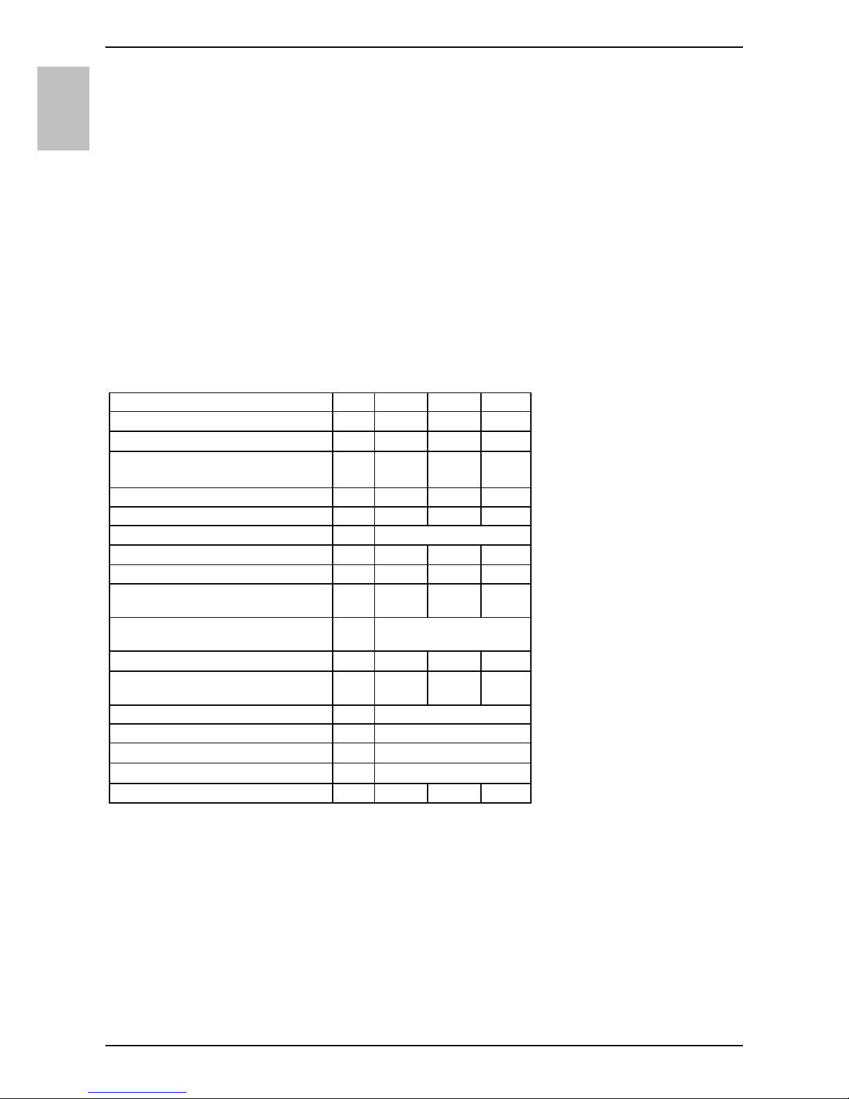
Type
TGR 50 X TGR 80 X TGR 100 X
Declared load profile M M L
Energy efficiency class 1) D D D
Water heating energy efficiency
(ƞwh) 1)
[%] 33,6 33,3 35,5
Annual electricity consumption 1) [kWh] 1522 1530 2884
Daily electricity consumption 2) [kWh] 7,26 7,38 13,57
Thermostat temperature settings eco
Value of "smart" 0 0 0
Volume [l] 47,5 76,1 96,1
Quantity of mixed water at 40 °С
V40 2)
[l] 66,5 96,5 131,4
Rated pressure
[МPa
(bar)]
0,6 (6)
Weight / Filled with water [kg] 21/71 27/107 31/131
Anti-corrosion of tank • • •
Power of electrical heater [W] 2000
Voltage [V~] 230
Protection class I
Degree of protection IP23
Heating time from 10 °С to 65 °С [h] 1 38 2 37 3 16
HR/BIH
9
UPOZORENJA
Uređaj mogu koristiti djeca starija od 8 godina i osobe sa smanjenim
tjelesnim, osjetnim ili mentalnim sposobnostima, odnosno nedovoljnim
iskustvom ili znanjem samo ako su pod nadzorom ili podučeni o uporabi
uređaja na siguran način i ako razumiju potencijalne opasnosti.
Djeca se ne smiju igrati uređajem.
Čišćenja i održavanja uređaja ne smiju obavljati djeca bez nadzora.
Ugradnju treba obaviti sukladno važećim propisima i prema uputama
proizvođača. Mora ju obaviti stručno osposobljen monter.
Za zatvoreni tlačni sustav priključenja, na dovodnu cijev grijalice vode
obvezatno ugradite sigurnosni ventil s nazivnim tlakom 0,6 MPa (6 bara),
0,9 MPa (9 bara) ili 1,0 MPa (10 bara) (vidi pločicu s natpisom), koji sprječava
povećanje tlaka u kotlu za više od 0,1 MPa (1 bar) iznad nazivnoga tlaka.
Voda može kapati iz odvodnog otvora sigurnosnoga ventila, stoga odvodni
otvor mora biti otvoren na atmosferski tlak.
Ispust sigurnosnoga ventila mora biti postavljen u smjeru nadolje i na
mjestu na kojem neće smrznuti.
Za pravilan rad sigurnosnoga ventila treba periodično obavljati kontrole
radi uklanjanja vodenoga kamenca i provjeravati da sigurnosni ventil nije
blokiran.
Između grijalice vode i sigurnosnoga ventila nije dozvoljeno ugrađivati
zaporni ventil jer bi se time onemogućila tlačna zaštita grijalice!
Prije priključenja na električne instalacije obvezatno prvo napunite grijalicu
vodom!
Grijalica je dodatnim termičkim osiguračem zaštićena u slučaju otkazivanja
radnoga termostata. U slučaju otkazivanja termostata, sukladno sigurnosnim
standardima, voda u grijalici može dostići temperaturu i do 130 °C. Prilikom
postavljanja vodovodnih instalacija obvezatno valja uvažavati činjenicu da su
moguća navedena preopterećenja temperature.
Ako budete isključivali grijalicu iz električne mreže, morate ispustiti vodu
zbog opasnosti od smrzavanja.
Molimo: eventualne kvarove na grijalici nemojte popravljati sami već
obavijestite najbliži ovlašteni servis o tome.
Naši su proizvodi opremljeni ekološki besprijekornim i zdravstveno
ispravnim neškodljivim komponentama te su proizvedeni tako da se u
svojoj posljednjoj fazi trajanja mogu što jednostavnije rastaviti i
reciklirati.
Reciklažom materijala smanjuju se količine otpada i potreba za
proizvodnjom osnovnih materijala (naprimjer kovine), što iziskuje puno
energije i uzrokuje emisije štetnih tvari. Postupcima reciklaže smanjuje se
potrošnja prirodnih izvora budući da se otpadni dijelovi od plastike i kovine
ponovno vraćaju u različite proizvodne procese.
Za više informacija o sustavu odlaganja otpadaka posjetite lokalni centar za
odlaganje otpadaka ili trgovca kod kojeg ste kupili proizvod.
10
HR/BIH
Poštovani kupci! Zahvaljujemo na povjerenju koje ste nam iskazali kupnjom
našega proizvoda.
MOLIMO PRIJE MONTAŽE I PRVE UPORABE POMNO PROČITAJTE UPUTE ZA
MONTAŽU, UPORABU I ODRŽAVANJE ELEKTRIČNE GRIJALICE VODE.
Grijalica je proizvedena sukladno važećim standardima i službeno je ispitana te su joj
dodijeljeni sigurnosni certifikat i certifikat o elektromagnetskoj kompatibilnosti.
Osnovna tehnička svojstva grijalice navedena su na natpisnoj tablici koja je
nalijepljena između priključnih cijevi. Priključenje grijalice na vodovodnu i električnu
mrežu može obaviti isključivo stručno osposobljena osoba.
Zahvate u njezinu unutrašnjost zbog popravka, uklanjanja vodenoga kamenca,
obavlja isključivo ovlaštena servisna služba.
MONTAŽA
Grijalicu montirajte što je moguće bliže potrošačkome mjestu. Ako uređaj za grijanje
ugrađujete u prostor u kojem su kada za kupanje ili tuš, obvezatno morate uzeti u
obzir zahtjeve standarda IEC 60364-7-701 (VDE 0100, Teil 701). Na zid ju pričvrstite
dvаma vijcima za zid, nazivnoga promjera od najmanje 8 mm. Ako je nosivost zida
koji je namijenjen montaži grijalice neodgovarajući, zid treba primjereno ojačati.
Grijalica se smije pričvrstiti na zid isključivo u uspravnome položaju.
Priključne i montažne
mjere grijalice [mm]
PRIKLJUČAK NA VODOVODNU MREŽU
Dovod i odvod vode na cijevima grijalice označeni su u boji. Dovod hladne vode
označen je plavom a odvod tople vode crvenom bojom.
Grijalicu možete priključiti na vodovodnu mrežu na dva načina. Zatvoreni, tlačni
sustav priključenja omogućuje odljev vode na više odljevnih mjesta, a sustav bez
tlaka dovoljan je samo za jedno odljevno mjesto. Ugradnja i odabir miješalice ovise o
izboru sustava priključenja.
Kod otvorenoga sustava bez tlaka ispred grijalice treba ugraditi nepovratni ventil koji
sprječava istjecanje vode iz kotla u slučaju prekida dovoda vode u mreži. Za taj
sustav priključenja morate koristiti protočnu miješalicu. Zapremnina vode u grijalici
povećava se uslijed zagrijavanja, što prouzrokuje kapanje vode iz cijevi miješalice.
Kapanje vode ne možete spriječiti jakim zatezanjem ručke na miješalici; tako samo
A B C
TGR 50 X 570 405 145
TGR 80 X 775 605 150
TGR 100 X 935 755 160
 Loading...