

Gorenje OTG 50 SM, OTG 100 SM, OTG 80 SM, OTG 120 SM, TGR 30-120 SM User Manual
OTG 50-120 SM
22
Dear buyer, thank you for purchasing our product.
Prior to the installation and first use of the electric water heater, please read these
instructions carefully.
THIS APPLIANCE IS NOT INTENDED FOR USE BY PERSONS (INCLUDING
CHILDREN) WITH REDUCED PHYSICAL, SENSORY OR MENTAL CAPABILITIES, OR
LACK OF EXPERIENCE AND KNOWLEDGE, UNLESS THEY HAVE BEEN GIVEN
SUPERVISION OR INSTRUCTIONS CONCERNING THE USE OF THE APPLIANCE BY
A PERSON RESPONSIBLE FOR THEIR SAFETY.
CHILDREN SHOULD BE SUPERVISED TO ENSURE THAT THEY DO NOT PLAY WITH
THE APPLIANCE.
In accordance with the latest guidelines, we have developed for our more demanding
customers the electric water heater OTG equipped with an intelligent electronic regulator
allowing the setting of the temperature of water in the heater as well as smart "ECOS"
mode of operation. The heater records your habits and after a while, it calculates the
optimal operating mode that enables minimal use of electric energy necessary to meet
your warm water needs.
This water heater has been manufactured in compliance with the relevant standards and
tested by the relevant authorities as indicated by the Safety Certificate and the
Electromagnetic Compatibility Certificate. The technical characteristics of the product are
listed on the label affixed between the inlet and outlet pipes. The installation must be
carried out by qualified staff. All repairs and maintenance work within the water heater, e.g.
lime removal or inspection/replacement of the protective anticorrosion anode, must be
carried out by an authorised maintenance service provider.
INSTALLATION
The water heater shall be installed as close as possible to the outlets. When installing the
water heater in a room with a bathtub or shower, take into account the requirements
defined in IEC Standard 60364-7-701 (VDE 0100, Part 701). It has to be fitted to the wall
using appropriate wall screws with a minimum diameter of 8 mm. A wall with a poor loadbearing capacity must be properly reinforced where the heater will be installed. The water
heater may only be fixed upon the wall vertically. We recommend the distance between the
water heater and the ceiling is large enough to allow simple replacement of the MG anode
(see dimension G in the Installation Drawing), in order to avoid unnecessary dismounting
of the heater during the servicing intervention.
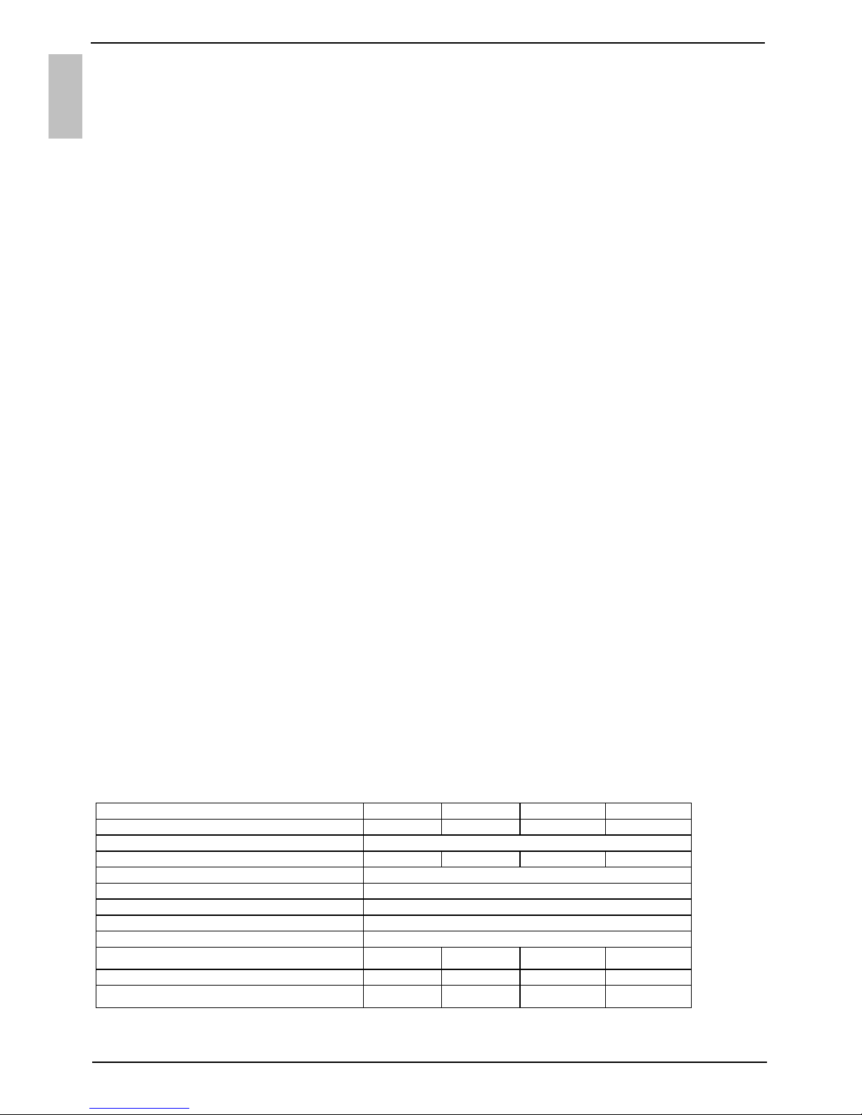
TECHNICAL PROPERTIES OF THE APPLIANCE
Type OT
G 50 SM OTG 80 SM OTG 100 SM OTG 120 SM
Volume [l]
50 80 100 120
Rated pressure [MPa (bar)]
0,6 (6) / 0,9 (9)
Weight / Filled with water [kg] 24/74 31/111 36/136 41/161
Anti-corrosion of tank enamelled & Mg Anode
Power of electrical heater [W]
2000
Connection voltage [V~]
230
Protection class I
Degree of protection IP24
Duration of heating to 75 °C 1) [h]
155 305 355 435
Quantity of mixed water at 40 °C [l]
94 148 194 226
Energy consumption 2) [kWh/24h]
0,99 1,26 1,71 1,81
1) Time for heating the whole content of heater if the initial temperature of cold water from water
supply is 15 °C.
EN
23
2) Energy consumption to maintain the temperature of water in the water heater at 65 °C if the
surrounding temperature is 20 °C, measured according to EN 60379.
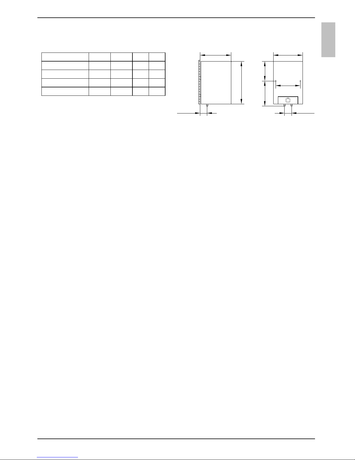
A B C G
OTG 50 SM 690 470 250 210
OTG 80 SM 950 735 245 360
OTG 100 SM 1125 900 255 360
OTG 120 SM 1300 900 430 510
Connection and installation
dimensions of the water heater [mm]
CONNECTION TO THE WATER SUPPLY
The water heater connections for the inlet and outlet of water are colour-coded. The inlet of
cold water is marked with blue colour, while the hot water outlet is marked with red colour.
The water heater can be connected to the water supply in two ways. The closed-circuit
pressure system enables several points of use, while the open-circuit gravity system
enables a single point of use only. The mixer taps must also be installed in accordance
with the selected installation mode.
The open-circuit gravity system requires the installation of a non-return valve in order to
prevent the water from draining out of the tank in the event of the water supply running dry
or being shut down. This installation mode requires the use of a cross-flow mixer tap. As
the heating of water expands its volume, this causes the tap to drip. The dripping cannot
be stopped by tightening it further; on the contrary, the tightening can only damage the tap.
The closed-circuit pressure system requires the use of pressure mixer taps. For safety
reasons the supply pipe must be fitted with a safety valve or alternatively, a valve of the
safety class that prevents the pressure in the tank from exceeding the nominal pressure by
more than 0.1 MPa (1 bar). The outlet opening on the relief valve must be equipped with
an outlet for atmospheric pressure.
The heating of water in the heater causes the pressure in the tank to increase to the level
set by the safety valve. As the water cannot return to the water supply system, this can
result in dripping from the outlet of the safety valve. The drip can be piped to the drain by
installing a catching unit just below the safety valve. The drain installed below the safety
valve outlet must be piped down vertically and placed in an environment that is free from
the onset of freezing conditions.
In case the existing plumbing does not enable you to pipe the dripping water from the
safety valve into the drain, you can avoid the dripping by installing a 3-litre expansion tank
on the inlet water pipe of the boiler.
In order to provide correct operation of the safety valve, periodical inspections of the relief
valve must be carried out by the user to eliminate any limescale and check if the safety
valve is blocked. To check the valve, open the outlet of the safety valve by turning the
handle or unscrewing the nut of the valve (depending on the type of the valve). The valve
is operating properly if the water comes out of the nozzle when the outlet is open.
EN
445
100
A
350
B
C
420
100
 Loading...