

Gorenje TEG 5 - 10 Instructions For Use Manual
TEG 5 - 10
2
3
Navodila za uporabo 4
SL
Instructions for Use 10
EN
Gebrauchsanweisung 16
DE
Upute za upotrebu 22
Uputstva za upotrebu 28
Udhëzime për përdorim 34
Упaтства за употребa 40
HR
BIH
SR
MNE
SQ
MNE
MK
4
SL
OPOZORILA
Aparat lahko uporabljajo otroci stari 8 let in starejši in osebe z zmanjšanimi
fizičnimi, čutnimi ali mentalnimi sposobnostmi ali s pomanjkanjem izkušenj oz.
znanjem če so pod nadzorom ali poučeni glede uporabe aparata na varen način
in da razumejo možne nevarnosti.
Otroci se ne smejo igrati z aparatom.
Čiščenja in vzdrževanja aparata ne smejo izvajati otroci brez nadzora.
Vgradnja mora biti izvedena v skladu z veljavnimi predpisi in po navodilih
proizvajalca. Izvesti jo mora strokovno usposobljen monter.
Grelnik je grajen za pretočni (netlačni) sistem priključitve na vodovodno
omrežje!
Pred električno priključitvijo morate grelnik obvezno najprej napolniti z
vodo.
Če boste grelnik vode izključili iz električnega omrežja, morate ob
nevarnosti zamrznitve, vodo iz njega iztočiti.
Prosimo Vas, da morebitnih okvar na grelniku ne popravljate sami, ampak
o njih obvestite najbližjo pooblaščeno servisno službo.
Naši izdelki so opremljeni z okolju in zdravju neškodljivimi
komponentami in so izdelani tako, da jih lahko v njihovi zadnji
življenjski fazi čim bolj enostavno razstavimo in recikliramo.
Z reciklažo materialov zmanjšujemo količine odpadkov in zmanjšamo
potrebo po proizvodnji osnovnih materialov (na primer kovine), ki
zahteva ogromno energije ter povzroča izpuste škodljivih snovi. Z reciklažnimi
postopki tako zmanjšujemo porabo naravnih virov, saj lahko odpadne dele iz
plastike in kovin ponovno vrnemo v različne proizvodne procese.
Za več informacij o sistemu odlaganja odpadkov obiščite svoj center za
odlaganje odpadkov, ali trgovca, pri katerem je bil izdelek kupljen.
SL
5
Cenjeni kupec, zahvaljujemo se Vam za nakup našega izdelka.
PROSIMO, DA PRED VGRADNJO IN PRVO UPORABO GRELNIKA VODE
SKRBNO PREBERETE NAVODILA.
Grelnik je izdelan v skladu z veljavnimi standardi in uradno preizkušen, zanj pa sta
bila izdana tudi varnostni certifikat in certifikat o elektromagnetni kompatibilnosti.
Njegove osnovne tehnične lastnosti so navedene na napisni tablici, nalepljeni med
priključnima cevema. Grelnik sme priključiti na vodovodno in električno omrežje le za
to usposobljen strokovnjak. Posege v njegovo notranjost zaradi popravila, odstranitve
vodnega kamna lahko opravi samo pooblaščena servisna služba.
VGRADNJA
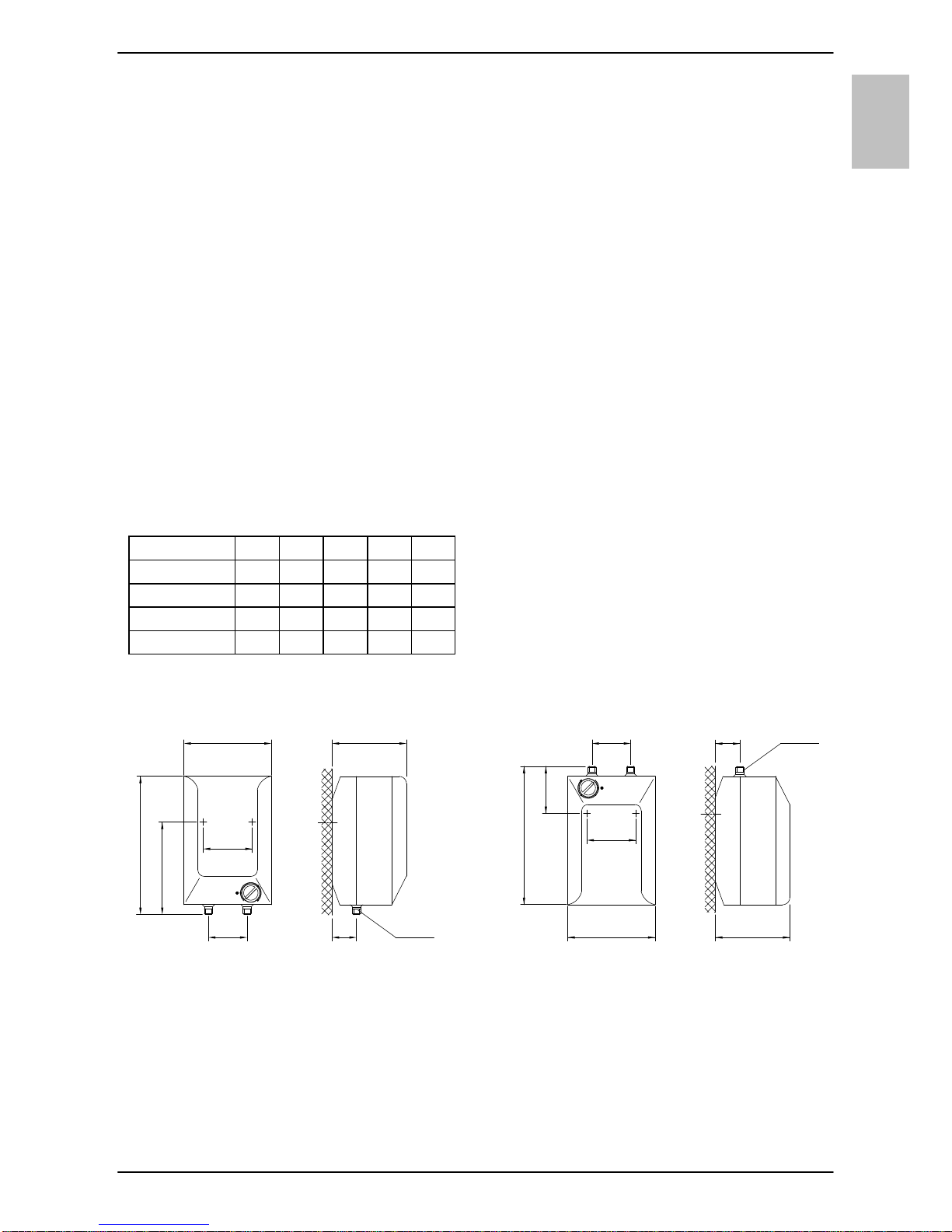
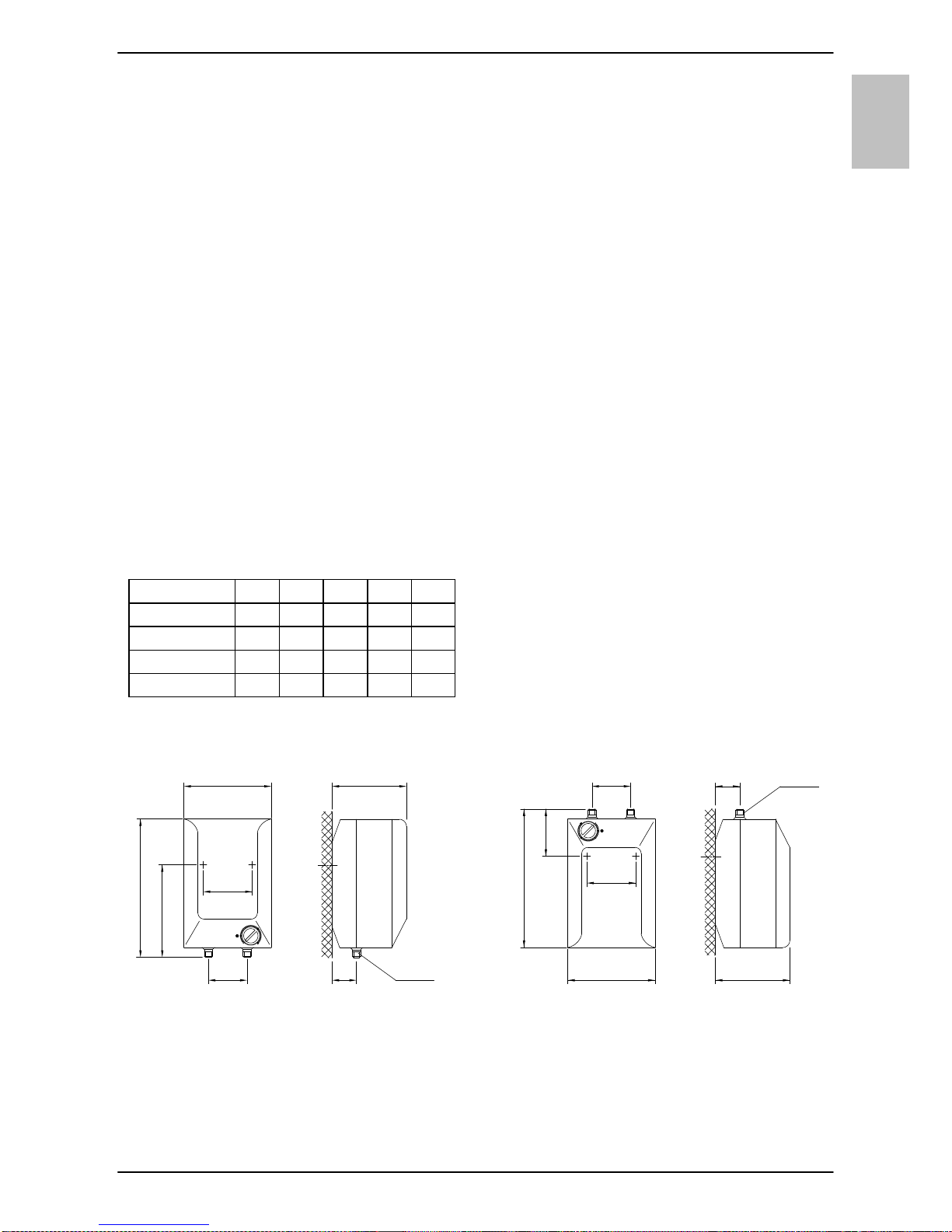
Grelnik vgradite po shemi in tabeli z merami za vgradnjo v prostor, kjer ne zmrzuje,
vendar čim bližje odjemnim mestom. Na steno ga pritrdite s stenskima vijakoma
nominalnega premera minimalno 5 mm.
Glede na vašo potrebo lahko izbirate med nadumivalniškim tipom (TEG 0520 O/A;
TEG 1020 O/A) in podumivalniškim tipom (TEG 0520 U/A; TEG 1020 U/A).
Priključne in montažne mere grelnika [mm]
Nadumivalniška izvedba Podumivalniška izvedba
A B C D E
TEG 0520 O/A 390 264 256 213
TEG 0520 U/A 390 138 256 213
TEG 1020 O/A 471 371 310 265
TEG 1020 U/A 471 196 310 265
D
100
B
A
E
70 G 1/2
G 3/8
100
D
C
A
70
E
140
140
6
SL
PRIKLJUČITEV NA VODOVODNO
OMREŽJE
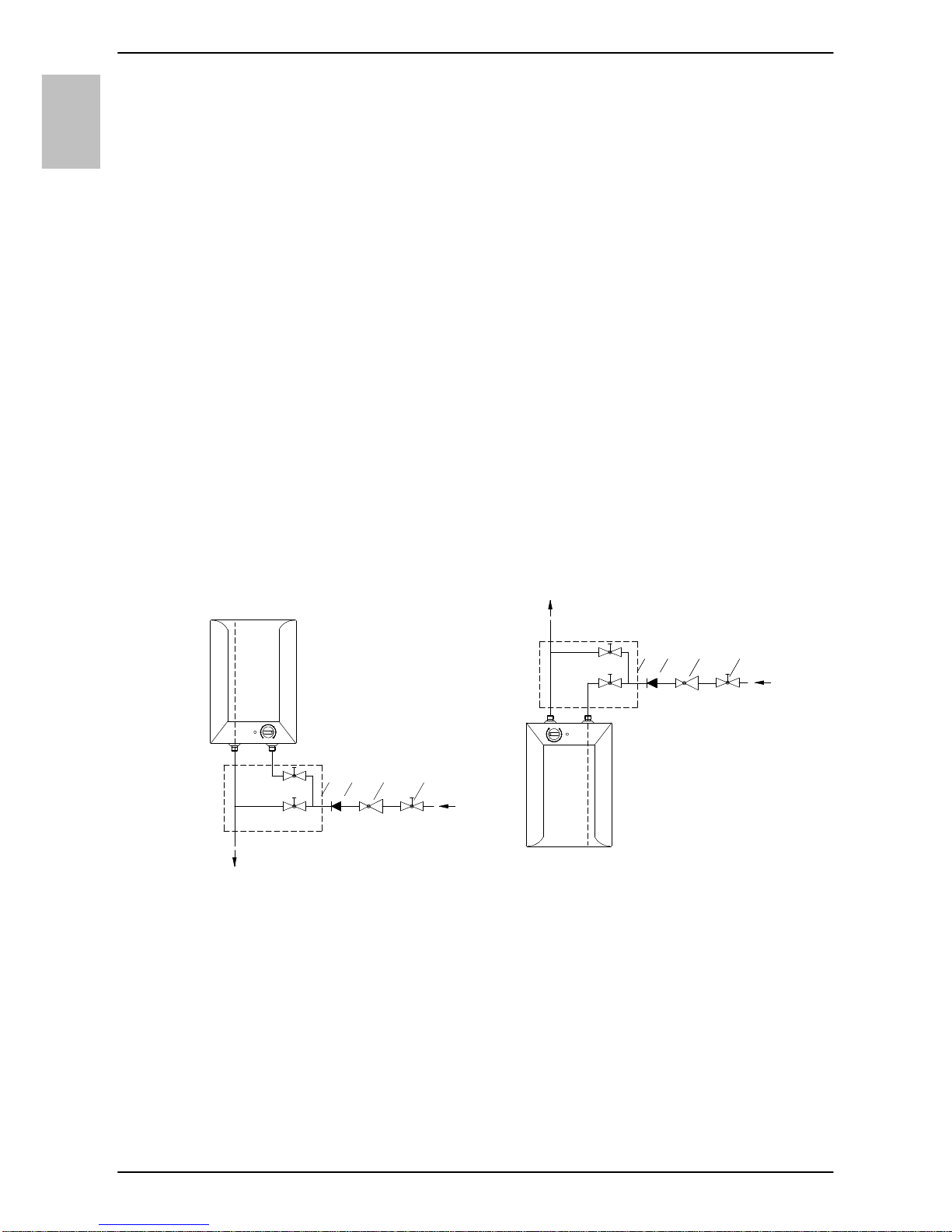
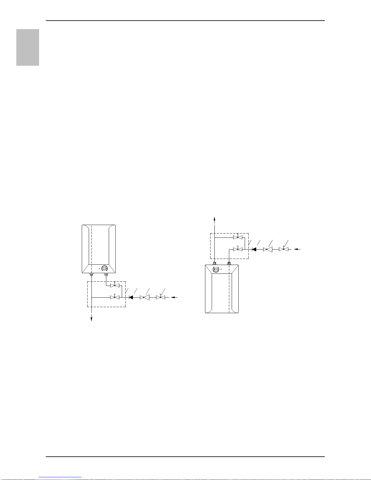
Grelnik je grajen za pretočni (netlačni) sistem priključitve. Ta sistem omogoča odjem
vode samo na enem odjemnem mestu. Priključitev je potrebno izvesti v skladu s
shemo vodovodnega priključka.
Za pretočni sistem priključitve morate vgraditi ustrezno mešalno baterijo. Za
nadumivalniško izvedbo potrebujete nadumivalniško pretočno baterijo, za
podumivalniško izvedbo pa podumivalniško pretočno baterijo. Dovod in odvod vode
sta na ceveh grelnika barvno označena. Dovod hladne vode je označen modro,
odvod tople vode pa rdeče. Na dotočno cev pred mešalno baterijo je potrebno
obvezno vgraditi nepovratni ventil, ki preprečuje iztekanje vode iz kotla, če v omrežju
zmanjka vode. Če tlak v vodovodnem omrežju presega 5 barov, morate pred
mešalno baterijo vgraditi še redukcijski ventil.
Pri izbiri pretočne mešalne baterije namenite posebno pozornost podatku
proizvajalca o padcih tlaka zaradi uporov, ki nastopajo pri pretoku vode skozi
mešalno baterijo. Pri popolnoma odprtem iztočnem ventilu ta ne sme presegati 0,2
bara. Na izlivno cev mešalne baterije prav tako ne smete priključiti nobene naprave
na vodni pogon ali vodnega razpršilca, ki bi lahko povzročil povečanje tlaka v kotlu
grelnika. Če se ne boste držali teh napotkov, lahko pride med obratovanjem do
poškodbe grelnika.
Nadumivalniška izvedba Podumivalniška izvedba
T
H
4a
3 12
T
H
4
3 12
Legenda:
1 - Zaporni ventil
2 - Redukcijski ventil
3 - Nepovratni ventil
4 - Pretočna mešalna baterija nadumivalniška
4a - Pretočna mešalna baterija -
podumivalniška
H - Hladna voda
T - Topla voda

SL
7
Pred električno priključitvijo morate grelnik obvezno napolniti z vodo. Pri prvi polnitvi
odprete ročico za toplo vodo na mešalni bateriji. Grelnik je napolnjen, ko voda priteče
skozi izlivno cev mešalne baterije. Če grelnika ob priključitvi ne boste napolnili z
vodo, bo ob prvem vklopu prišlo do poškodbe toplotne varovalke in grelnik sploh ne
bo deloval.
PRIKLJUČITEV NA ELEKTRIČNO
OMREŽJE
Priključitev grelnika na električno omrežje mora potekati v skladu s standardi za
električne napeljave. V električni inštalaciji mora biti vgrajena priprava za ločitev vseh
polov. Grelnik priključite na električno omrežje preko priključnega kabla. Če želite
vgrajeni kabel nadomestiti z novim, daljšim, lahko vgrajeni kabel odstranite, novega
pa pritrdite v kabelsko uvodnico ter žice kabla privijačite v priključno sponko. Da to
lahko storite morate najprej sneti plastično oblogo grelnika.
To storite tako, da najprej odstranite ploščico (velja za modele z vstavno ploščico), ki
je vstavljena v sprednjo stran plastične obloge. Ploščico sprostite na ta način, da v
režo med vstavno ploščico in plastično oblogo najprej ob gumbu termostata nato pa
še na strani nasproti gumba previdno porinete izvijač. Ko ploščico sprostite na obeh
straneh, jo lahko odstranite z roko. Nato odstranite gumb termostata in odvijete
pritrdilni vijak pod gumbom. Nazadnje odvijačite še vse vijake za pritrditev plastične
obloge in oblogo odstranite.
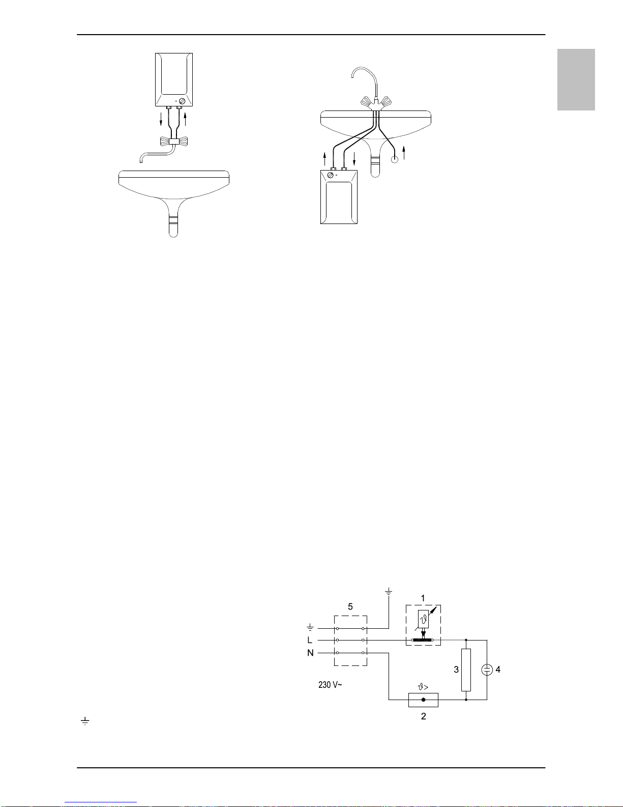
Legenda:
1 - Termostat
2 - Toplotna varovalka
3 - Grelo
4 - Kontrolna svetilka
5 - Priključna sponka
L - Fazni vodnik
N - Nevtralni vodnik
- Zaščitni vodnik
Shema električne vezave
8
SL
OPOZORILO: Pred vsakim posegom v njegovo notranjost morate grelnik
obvezno izključiti iz električnega omrežja!
UPORABA IN VZDRŽEVANJE
Po priključitvi na vodovodno in električno omrežje je grelnik pripravljen za uporabo.
Z vrtenjem gumba na termostatu, ki je na prednji strani zaščitnega pokrova, izbirate
željeno temperaturo vode do 75 °С. Priporočamo nastavitev gumba na položaj "e".
Takšna nastavitev je najbolj varčna; pri njej bo temperatura vode približno 41 °С pri
TEG 0520 oz. približno 35 °С pri TEG 1020, izločanje vodnega kamna in toplotna
izguba pa bosta manjša kot pri nastavitvah na višjo temperaturo (poz. II - 55 °C in III -
75 °C). Delovanje električnega grela pokaže kontrolna svetilka, ki sveti vse dokler se
voda v grelniku ne segreje do izbrane temperature ali do namenskega izklopa. V
grelniku se zaradi segrevanja prostornina vode povečuje, to pa povzroči kapljanje iz
cevi mešalne baterije. Z močnim zategovanjem ročaja na mešalni bateriji kapljanja
vode ne morete preprečiti, temveč baterijo lahko pokvarite.
Če grelnika ne mislite uporabljati dalj časa, zavarujete njegovo vsebino pred
zmrznitvijo na ta način, da elektrike ne izklopite, gumb termostata pa nastavite na
položaj " ". Pri tej nastavitvi bo grelnik vzdrževal temperaturo vode pri približno 9 °С.
Če boste grelnik iz električnega omrežja izklopili, morate ob nevarnosti zmrznitve
vodo iz njega iztočiti Voda iz grelnika se izprazni skozi dotočno/odtočno cev grelnika.
Zunanjost grelnika čistite z blagimi tekočimi čistili. Ne uporabljajte razredčil in grobih
čistilnih sredstev.
Z rednimi servisnimi pregledi boste zagotovili brezhibno delovanje in dolgo življenjsko
dobo grelnika. Prvi pregled naj pooblaščena servisna služba opravi približno dve leti
po priključitvi. Ob pregledu se po potrebi očisti vodni kamen, ki se glede na kakovost,
količino in temperaturo porabljene vode nabere v notranjosti grelnika. Servisna
služba vam bo po pregledu grelnika glede na ugotovljeno stanje priporočila tudi
datum naslednje kontrole.
Prosimo Vas, da morebitnih okvar na grelniku ne popravljate sami, ampak o
njih obvestite najbližjo pooblaščeno servisno službo.
SL
9
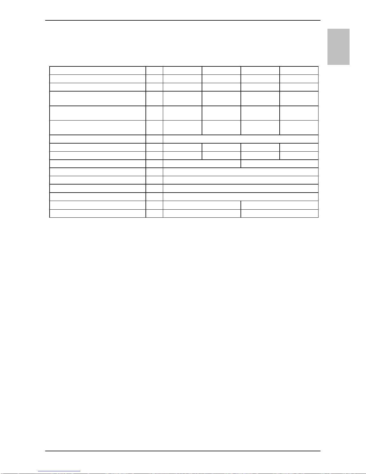
TEHNIČNE LASTNOSTI APARATA
* pozicija termostata na oznaki "e" ustreza pri 41 °C pri TEG 0520 oz. 35 °C pri TEG 1020
1) Uredba komisije EU 812/2013; EN 50440
2) EN 50440
PRIDRŽUJEMO SI PRAVICO DO SPREMEMB, KI NE VPLIVAJO NA
FUNKCIONALNOST APARATA.
Navodila za uporabo so na voljo tudi na naših spletnih straneh
http://www.gorenje.com .
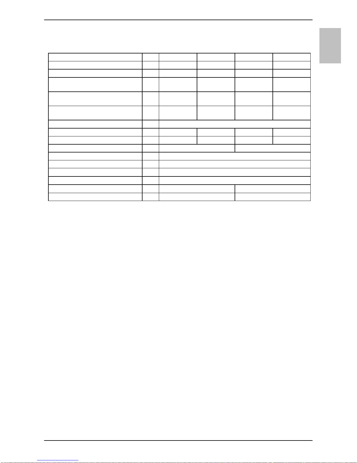
Tip TEG 0520 O/A TEG 0520 U/A TEG 1020 O/A TEG 1020 U/A
Določeni profil obremenitve XXS XXS XXS XXS
Razred energijske učinkovitosti A A A A
Energijska učinkovitost
pri ogrevanju vode (ƞwh)
1)
[%] 35,2 35 35,3 35,1
Letna poraba
električne energije
1)
[kWh] 525 527 523 525
Dnevna poraba
električne energije
2)
[kWh] 2,475 2,49 2,464 2,477
Nastavitev temperature termostata e *
Vrednost "smart" 0 0 0 0
Prostornina [l] 5,5 5,7 9,8 9,9
Masa / napolnjen z vodo [kg] 3,5 / 8,5 4 / 14
Priključna moč [W] 2000
Napetost [V~] 230
Razred zaščite I
Stopnja zaščite IP24
Čas segrevanja od 10 °С do 65 °С [min] 10 20
Mere embalaže [mm] 215x265x425 275x320x500
10
EN
WARNINGS
The appliance may be used by children older than 8 years old, elderly
persons and persons with physical, sensory or mental disabilities or lacking
experience and knowledge, if they are under supervision or taught about safe
use of the appliance and if they are aware of the potential dangers.
Children should not play with the appliance.
Children should not clean or perform maintenance on the appliance
without supervision.
Installation should be carried out in accordance with the valid regulations
and according to the instructions of the manufacturer and by qualified staff.
The water heater is constructed for cross-flow (non-pressure) system of
installation!
Before connecting it to the power supply, the water heater must be filled
with water!
If the heater is to be disconnected from the power supply, please drain any
water from the heater to prevent freezing.
Please do not try to fix any defects of the water heater on your own. Call
the nearest authorised service provider.
Our products incorporate components that are both environmentally
safe and harmless to health, so they can be disassembled as easily as
possible and recycled once they reach their final life stage.
Recycling of materials reduces the quantity of waste and the need for
production of raw materials (e.g. metals) which requires a substantial
amount of energy and causes release of harmful substances. Recycling
procedures reduce the consumption of natural resources, as the waste parts
made of plastic and metal can be returned to various production processes.
For more information on waste disposal, please visit your waste collection
centre or the store where the product was purchased.
EN
11
Dear buyer, thank you for purchasing our product.
Prior to the installation and first use of the electric water
heater, please read these instructions carefully.
This water heater has been manufactured in compliance with the relevant standards
and tested by the relevant authorities as indicated by the Safety Certificate and the
Electromagnetic Compatibility Certificate. The technical characteristics of the product
are listed on the label affixed between the inlet and outlet pipes. The installation must
be carried out by qualified staff. All repairs and maintenance work within the water
heater, e.g. lime removal, must be carried out by an authorised maintenance service
provider.
INSTALLATION
The water heater shall be built in according to the drawing and table with dimensions
in a premise where there is no frost, as close as possible to the water outlets. It has
to be fitted to the wall using appropriate wall screws with a minimum diameter of 5
mm.
With regard to the needs, you can chose execution above the sink (TEG 0520 O/A;
TEG 1020 O/A) or an execution under the sink (TEG 0520 U/A; TEG 1020 U/A).
Connection and installation dimensions of the water heater [mm
Execution above the sink Execution under the sink
A B C D E
TEG 0520 O/A 390 264 256 213
TEG 0520 U/A 390 138 256 213
TEG 1020 O/A 471 371 310 265
TEG 1020 U/A 471 196 310 265
D
100
B
A
E
70 G 1/2
G 3/8
100
D
C
A
70
E
140
140
12
EN
CONNECTION TO THE WATER SUPPLY
The water heater is constructed for cross-flow (non-pressure) system of installation.
This system enables supply of water only at one outlet point. The connection must be
performed correspondingly to the diagram of the water supply.
For cross-flow system of installation an adequate mixing tap must be purchased. For
the execution above sink is needed a mixing tap above sink, and for execution under
the sink the mixing tap under the sink. Inlet of cold water is marked with blue colour
and the outlet of hot water is marked with red colour. Upon the inlet pipe before the
mixing tap it is mandatory to built-in a non-return valve preventing the running of
water of the tank if the water in the network runs short. If the pressure in water supply
network surpasses 5 bar, before the mixing tap also a reduction valve must be built
in.
By choice of the cross-flow mixing tap, particular attention must be paid to the data of
supplier about reduction of pressure by the resistance appearing by flow of water
through the mixing tap. By entirely open outlet valve this must not surpass 0,2 bar. To
the outlet pipe of mixing tap no device driven by water or spray nozzle may be
connected, which could cause the increase of pressure in the tank of the water
heater. If these instructions shall not be respected during the operation, a damage of
the heater may occur.
Execution above the sink Execution under the sink
T
H
4a
3 12
T
H
4
3 12
Legend:
1 - Closing valve
2 - Pressure reduction valve
3 - Non-return valve
4 - Cross-flow mixing tap - above sink
4a - Cross-flow mixing tap - under sink
H - Cold water
T - Hot water
EN
13
Prior to the electric connection, the heater must be obligatorily filled with water. By
first filling the faucet for the hot water upon the mixing tap must be opened. The
heater is filled with water when the water starts to run through the outlet pipe of the
mixing tap. If the heater at connection would not be filled with water, at first switchingon the damage of thermal fuse shall occur and the heater shall not operate at all.
CONNECTING THE WATER HEATER TO
THE POWER SUPPLY NETWORK
Connection of the water heater to the electric network must be performed according
to standards for electric installation. The heater shall be connected to electric power
supply over electric cable with plug. If the built-in cable shall be replaced with a new
longer, the built-in cable may be removed and the new connecting cable inserted
where the cable wires shall be screwed to the connection terminal. In order to do this
the plastic lining of the water heater must be removed. This is done so that at first the
plate is removed, inserted in the front side of the plastic lining. The plate is released
so that in the slot between the inserted plate and the plastic lining at first at the
thermostat knob and on the side in front of the knob cautiously a screwdriver is
pushed in. When the plate is released at both sides, it can than be removed by hand.
Than the thermostat knob is removed and the screw under the knob is unscrewed. At
last also all four screws for fixing of plastic lining are unscrewed and the lining
removed.
Legend:
1 - Thermostat
2 - Thermal cut-off
3 - Electric heating element
4 - Pilot lamp
5 - Connection terminal
L - Live conductor
N - Neutral conductor
- Earthing conductor
Electric installation
14
EN
CAUTION: Before any intervention into the interior of the water heater,
disconnect it from the power supply network! This intervention may only be
performed by a trained professional!
OPERATION AND MAINTENANCE
After connecting to the water and power supply, the heater is ready for use. By
turning the knob of thermostat at the front side of the protecting cover, the wished
temperature of water 75 °C is chosen. We recommend the adjustment of the knob to
the position "e". Such an adjustment is the most economic, with it the temperature of
water shall be approximately 41 °C in case of TEG 0520 or 35 °C in case of TEG
1020, the excretion of lime-stone and thermal loss shall be smaller as by adjustment
to higher temperature (poz. II - 55 °C in III - 75 °C).
The operation of electric immersion heaters is shown by pilot light which is lit during
the time until the water in the heater is heating to the chosen temperature or to the
intended switch off. During the heating the volume of water in the heater is
increasing, which causes the dropping of water from the mixing valve. By strong
squeezing of the mixing valve the dropping can not be stopped but the mixing valve
can be damaged.
When the heater shall not be used during a longer time, its contents must be
protected against freezing so that the electricity shall not be switched off, but the
thermostat knob shall be adjusted to the position " ". With this adjustment the heater
shall maintain the water temperature by approximately 9 °C. But when the heater is
switched-off the electric network, at risk for freezing, the water must be emptied from
it. Water from the heater is drained through the inlet/outlet pipe of the heater.
The outside of the heater is cleaned by mild solution of detergent. The solvents or
rough cleaning means should not be used. By regular service check impeccable
operation shall be assured and a long lifetime of the heater. The first check must be
performed by authorised service workshop after approximately two years after the
first connection. At check, it necessary lime stone must be cleaned which with regard
to the quality, quality and temperature of the water used is gathered in the inside of
the water heater. Service workshop shall after check recommend also the date of
next check.
Never try to repair any possible faults of the heater by yourself, but inform
about it the nearest authorised service workshop.
EN
15
TECHNICAL PROPERTIES OF THE
APPLIANCE
* The "e" position of the regulation knob corresponds to a water temperature of approx. 41 °C by TEG 0520
and 35 °C by TEG 1020
1) EU Regulation 812/2013; EN 50440
2) EN 50440
WE RESERVE THE RIGHT TO MAKE CHANGES THAT DO NOT IMPAIR THE
FUNCTIONALITY OF THE DEVICE.
The user manual can also be found at our website http://www.gorenje.com .
Type TEG 0520 O/A TEG 0520 U/A TEG 1020 O/A TEG 1020 U/A
Declared load profile XXS XXS XXS XXS
Energy efficiency class
1)
A A A A
Water heating energy efficiency
(ƞwh)
1)
[%] 35,2 35 35,3 35,1
Annual electricity consumption
1)
[kWh] 525 527 523 525
Daily electricity consumption
2)
[kWh] 2,475 2,49 2,464 2,477
Thermostat temperature settings e *
Value of "smart" 0 0 0 0
Volume [l] 5,5 5,7 9,8 9,9
Weight / Filled with water [kg] 3,5 / 8,5 4 / 14
Power of electrical heater [W] 2000
Voltage [V~] 230
Protection class I
Degree of protection IP24
Heating time from 10 °С to 65 °С [min] 10 20
Packaging dimensions [mm] 215x265x425 275x320x500
 Loading...