

Gorenje TC 80-120 Z, TC 80-120 ZNT Instructions For Use Manual
TC 80-120 Z/ZNT
2
Instructions for Use 3
Gebrauchsanweisung 20
DE
EN
Notice d’utilisation 38
FR
Instrukcja obsługi 92
PL
Návod k obsluze 109
CS
Návod na obsluhu 126
SK
Istruzioni per l'uso 56
IT
Instrucciones de uso 74
ES
3
EN
WARNINGS!
The appliance may be used by children older than 8 years old, elderly
persons and persons with physical, sensory or mental disabilities or lacking
experience and knowledge, if they are under supervision or taught about safe
use of the appliance and if they are aware of the potential dangers.
Children should not play with the appliance.
Children should not clean or maintain the appliance without supervision.
Always transport the heat pump in an upright position; exceptionally, it
may be tilted by 35° in all directions. Be careful not to damage the housing or
the vital component parts of the heat pump during transport.
The heat pump is not intended for industrial use and use in premises
where corrosive and explosive substances are present.
The connection of the heat pump to the mains should be performed in
accordance with standards for electrical appliances. An all-poles disconnect
switch should be installed between the heat pump and the mains in accordance
with the national installation standards.
The heat pump should not be in operation without water in the hot water
tank, because of danger of destruction of the compressor!
The installation should be performed in accordance with the valid
regulations and the instructions of the manufacturer. It should be performed by
a professionally trained installation expert.
It is necessary to install a safety valve with a rated pressure of 0.6 MPa
(6 bar) to the inlet pipe of the heat pump, to prevent the pressure in the boiler
from rising for more than 0.1 MPa (1 bar).
Water may drip from the outlet opening of the safety valve, so the outlet
opening should be set to atmospheric pressure.
The outlet of the safety valve should be installed facing downwards and in
a non-freezing area.
To ensure proper functioning of the safety valve, the user should perform
regular controls to remove limescale and make sure the safety valve is not
blocked.
Do not install a stop valve between the heat pump and the safety valve,
because it will impair the functioning of the safety valve!
Before the beginning of the operation two 90° elbows must be installed to
the top of the appliance (ø125 mm), each facing in the opposite direction. The
premises must be properly ventilated.
The elements in the electronic control unit are live even after pressing the
off field (9) on the heat pump.
If you disconnect the heat pump from the power supply, please drain any
water from the pump to prevent freezing.
Water can be drained from the pump through the boiler inlet pipe. For this
purpose it is advisable to install a special element or outlet valve between the
inlet pipe and safety valve.
Please do not try to fix any defects of the heat pump on your own. Call the
nearest authorised service provider.
EN
4
This product contains fluorinated greenhouse gases. Hermetically sealed.
Our products incorporate components that are both environmentally
safe and harmless to health, so they can be disassembled as easily as
possible and recycled once they reach their final life stage.
Recycling of materials reduces the quantity of waste and the need for
production of raw materials (e.g. metals) which requires a substantial
amount of energy and causes release of harmful substances. Recycling
procedures reduce the consumption of natural resources, as the waste parts
made of plastic and metal can be returned to various production processes.
For more information on waste disposal, please visit your waste collection
centre or the store where the product was purchased.
INTRODUCTION
Dear Customer,
Thank you for purchasing this Gorenje product. This heat pump for heating sanitary
water is one of the most advanced appliances in its class. Its material, design and
testing were made in compliance with related applicable standards.
Power, capacity and safety systems were thoroughly tested. Tests were made
individually for each component part, as well as for the finished product, according to
international quality standards.
Please read these Instructions for Installation and Use carefully before use in order to
prevent eventual problems that may cause damage to the product.
Keep this Manual for future reference, as a source of information on the details of the
heat pump operation or its maintenance. Instructions for Installation and Use can also
be found on our website http://www.gorenje.com .
Of course, you can always contact any of our experienced authorised servicing
technicians for occasional maintenance.

EN
5
USE
This unit is designed for production of sanitary water in households and at premises
where daily consumption of hot water (40 °C) does not exceed 150 l to 250 l. The
appliance must be connected to water supply mains and to the power supply grid.
The air intake and air exhaust may also be provided by designing the inlet and outlet
drain from and to the adjacent room.
In case of installing the unit in a room with a bathtub or shower tub, take into account
the requirements defined in the IEC 60364-7-701 standard (VDE 0100, Teil 701). To
mount the unit on the wall, use special wall bolts with a nominal diameter of minimum
8 mm and always mount the unit in an upright position. Make sure the mounting
location on the wall is adequately reinforced if the wall is not strong enough. We
recommend leaving enough space between the floor and unit as to provide easy
access to the Mg anode (for maintenance or replacement purposes – Fig. 4). If not,
the unit will need to be dismounted from the wall before servicing.
The heat pump may not be used for purposes other than those defined in these
Instructions. The unit is not designed for industrial use or use in rooms where
corrosive or explosive substances are present.
The manufacturer shall not assume any liability for damages caused by incorrect
installation or misuse that are not in compliance with the Instructions for installation
and use.
The instructions for use are a component and important part of this product and must
be delivered to the customer. Read the warnings carefully, as they contain important
directions related to safety during operation, use and maintenance.
Keep these Instructions for later use.
The marking of the heat pump is stated on the nameplate located on the bottom side
of the unit, between both inlet pipes for sanitary water.
Once the packaging is removed, check the contents. When in doubt, contact your
dealer. Never let children play with the packaging parts (clamping, plastic bags,
expanded polystyrol, etc.) – potential risk. Make sure to remove and dispose of the
packaging safely and in an environmentally friendly way.
STORAGE AND TRANSPORT
Store the heat pump in an upright position, in a clean and dry place.
EN
6
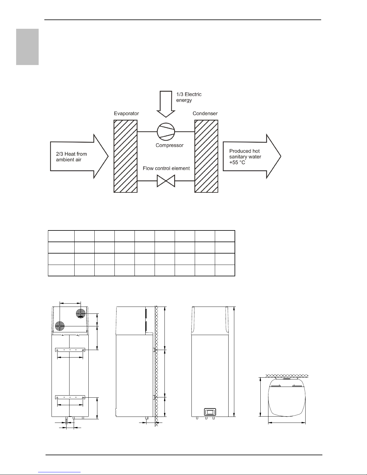
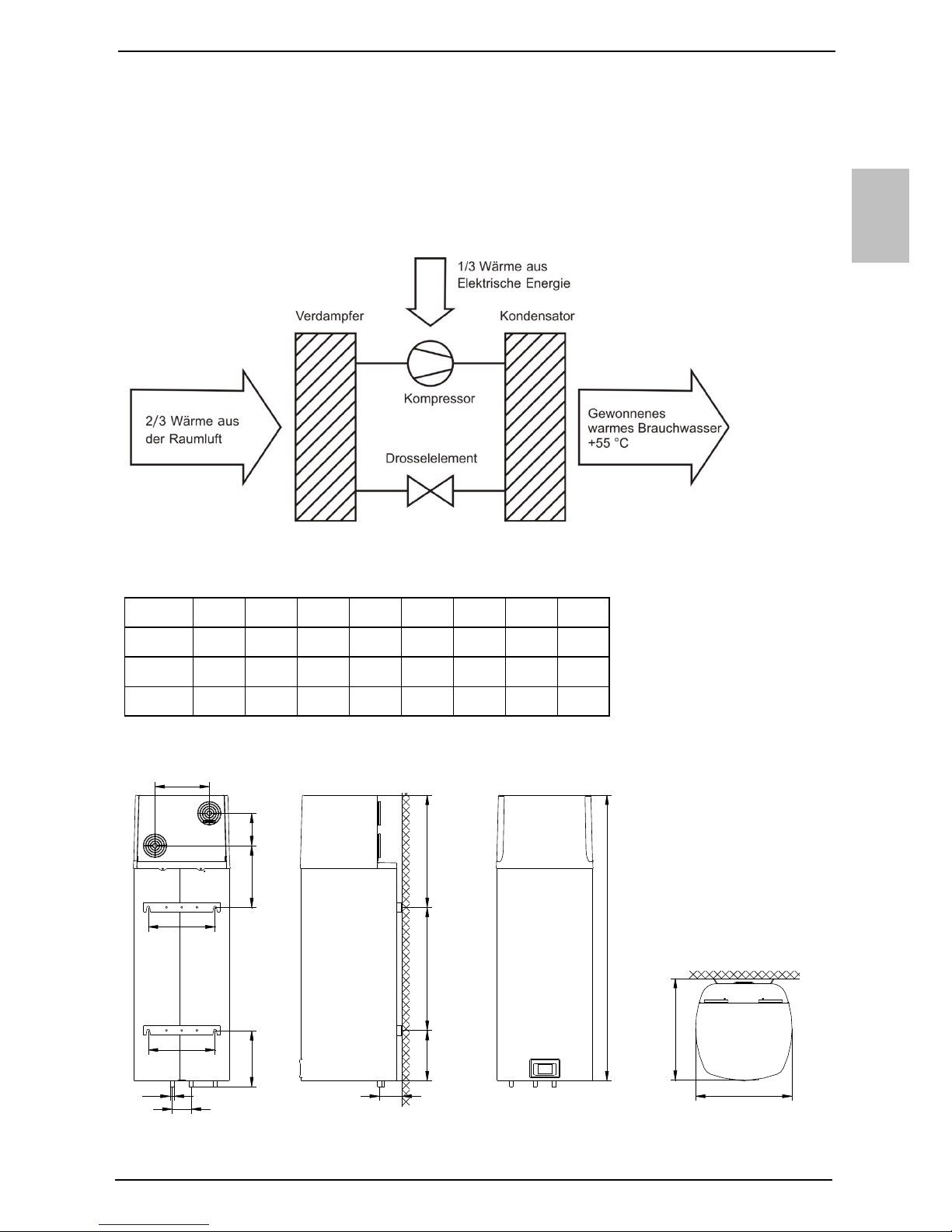
THE PRINCIPLE OF OPERATION
The heat pump is in fact a thermodynamic heat generator, drawing heat from a low
temperature level (e.g.: heat from the ambient air) to a higher temperature level (e.g.:
hot sanitary water).
The heat drawn from the ambient air, along with the electric energy, generates
heating energy, which is available for heating the sanitary water.
Fig. 1: Chart of energy flow through the heat pump unit
DIMENSIONS
* - DIN norm
** - NF norm
Fig. 2: Connection and installation dimensions of the heat pump [mm]
A B C * C ** D * D ** E * E **
TC 80
1197 345 100 175 100 230 G 1/2 G 3/4
TC 100
1342 490 100 175 100 230 G 1/2 G 3/4
TC 120
1497 645 100 175 100 230 G 1/2 G 3/4
A
264
B
589
C
294
350
350
D
E
324
506
533
285
170
EN
7
INSTALLATION OF THE HEAT PUMP
The heat pump can be used using the ambient air or air from other premises. The
heat pump must be installed in a frost-free room. When selecting a place for
installation, particular attention should be paid that the selected air intake location is
dust free, because dust has adverse effects on the heat pump performance. When
selecting the place of installation, pay attention to the solidity of the wall – can it take
the weight of the heat pump together with the weight of the water inside the boiler?
Take all the necessary precautions to prevent the operation noise and vibrations from
transferring through the walls to the premises where this would be disturbing
(bedrooms, rest areas). Do not install the heat pump and its air intake in premises
with other air consumption appliances (gas boilers, solid-fuel fireplaces, dust
extraction appliances etc.) During installation, please bear in mind the minimum
distances from the wall, ground and ceiling. The condensate outlet from the heat
pump is placed on the bottom left side in the form of a plastic tube with an external
diameter of ø18 mm. This tube should be connected to the external condensate
outlet pipe and led to the sewage system or a container. The quantity of condensate
depends on air temperature and humidity when the heat pump is in operation.
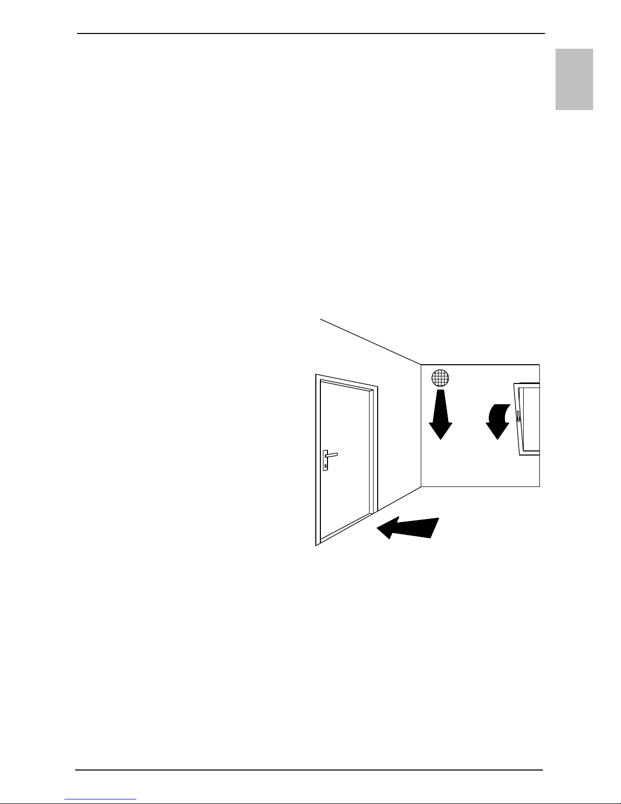
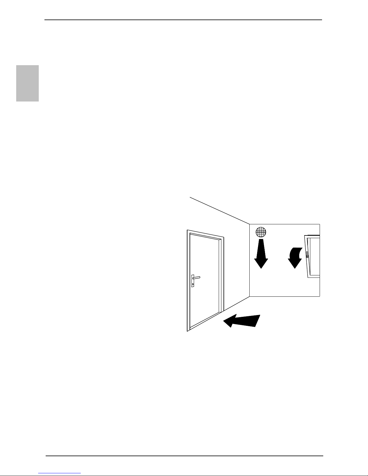
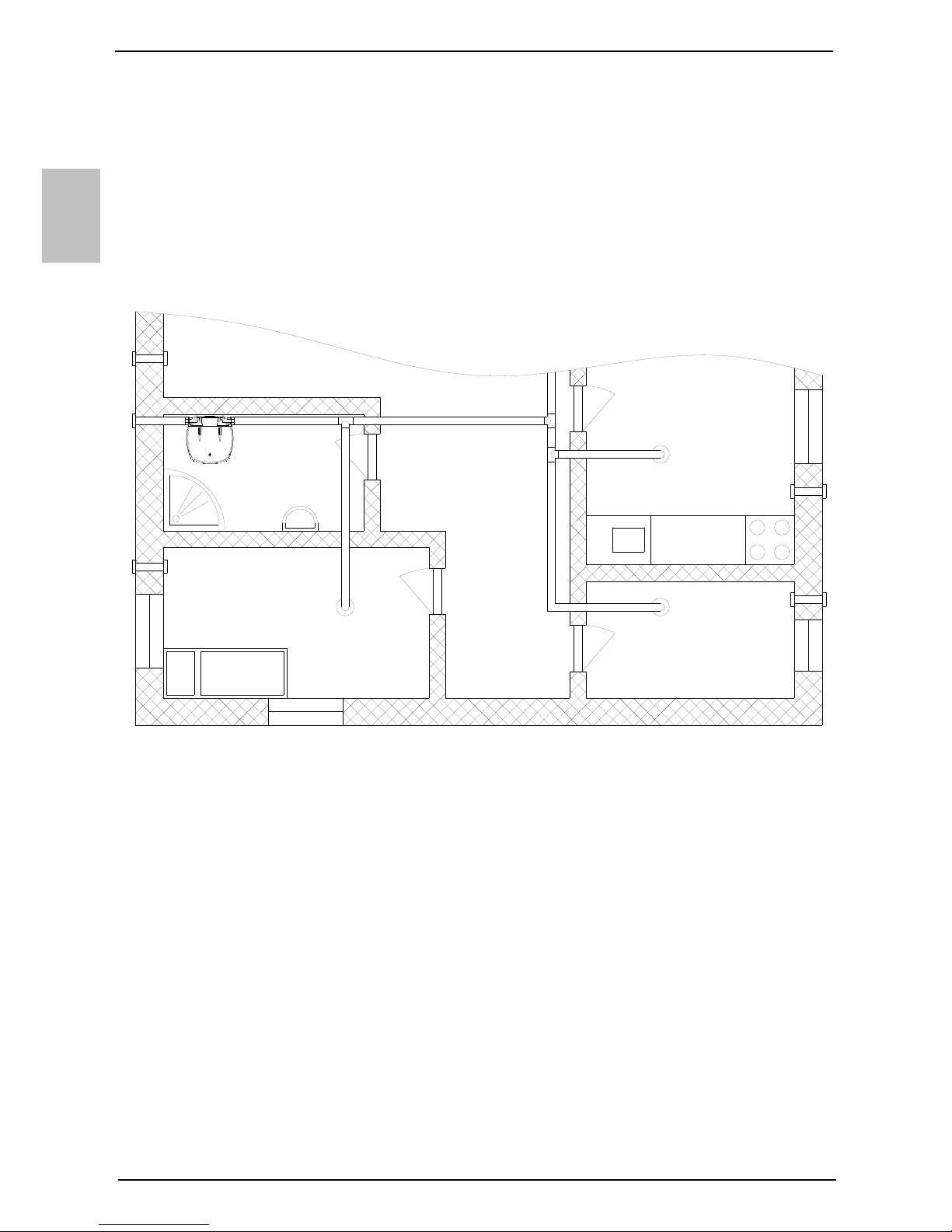
To prevent pressure depression in
the building, fresh air must be
regularly supplied to the premises.
The desired rate of air exchange for
a residential building is 0.5. This
means that the entire quantity of air
in the building is exchanged every
two hours.
Connecting the heat pump to the
same pipeline as the kitchen
extractor fan or taking air out of
several smaller apartments or suites
is not allowed.
Fig. 3: Ventilation
To minimize the transfer of noise and vibrations through walls into the premises
where this would be disturbing (bedrooms, rest areas), please take the following
measures:
- install flexible joints for hydraulic connections
- install a flexible tube for the pipeline of inlet/outlet air
- plan vibration insulation for wall openings
- plan noise dampers for inlet/outlet air
- pipelines for inlet/outlet air should be attached using noise dampers
- plan vibration insulation against the wall
EN
8
a) Operation using ambient air
In this type of operation, the device heats
domestic water using only the amount of
energy generated by the air from the room
where the device is installed. The heat pump
must be installed in a ventilated, frost-free
room, possibly in the vicinity of other heating
sources. For optimal performance of the heat
pump, we recommend a sufficiently large and
well ventilated room with the temperature
ranging between 15 °C and 25 °C. It is vital to
ensure sufficient intake of air in the room.
Elbows must be installed on the heat pump
and turned so that they prevent the mixing of
air. Heat losses are greater in premises with
colder air.
Models TC…Z
If the heat pump is installed in a frost-free
room and the temperature is under 7 °C,
heaters for the heating of domestic water will
be switched on. The heat pump operates in
reserve mode.
Models TC…ZNT
If the heat pump is installed in a frost-free
room and the temperature is under 7 °C, the
heat pump operates in the normal mode of
operation.
b) Operation using air from other premises
In this type of operation, the heat pump uses air from other premises via a pipeline
system. It is advisable to insulate the pipeline system to prevent the formation of
condensate.
In case of using air from outside, the external part must be covered so as to prevent
the intrusion of dust or snow into the appliance. Besides the drag in the pipes and
elbows, the user should be aware that increased drag also increases noise levels.
In case of using air from outside, the user should adhere to the minimum diameter of
the pipes ø125 mm or □150x70. Instructions for designing the pipeline system can
also be found on our website http://www.gorenje.com .
Models TC…Z
To ensure normal operation of the heat pump, the temperature of the captured
external air should be at least 7 °C. To make sure the operation of the pump is
effective at all times, you can install dampers to take air from the premises and then
return it either to the premises or outside. If the temperature of air is under 7 °C,
heaters for the heating of domestic water are switched on. The heat pump operates
in reserve mode.
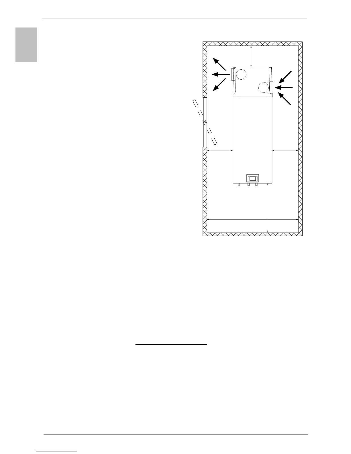
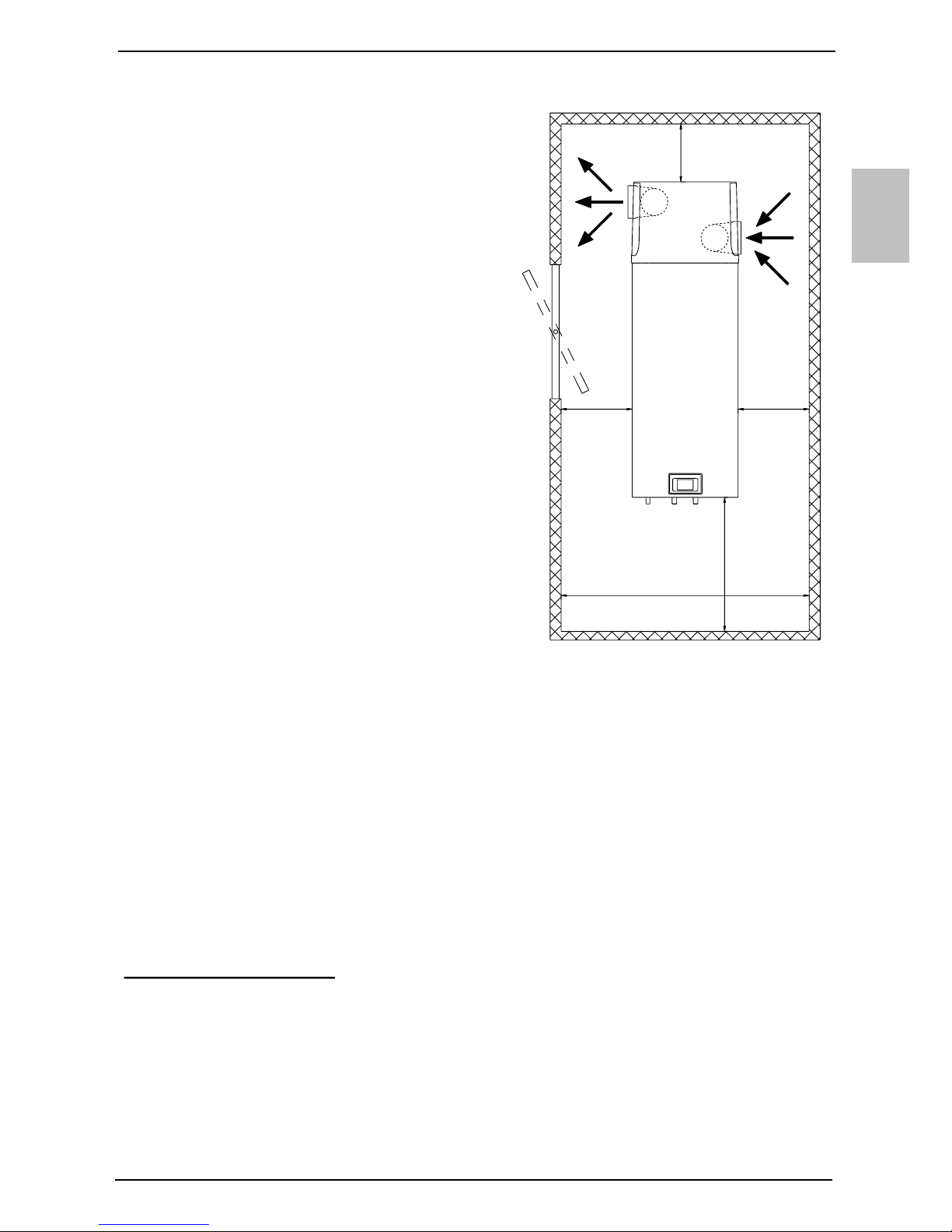
min 25 cmmin 25 cm
min 150 cm
min 20 cm
min 75 cm
Fig. 4: Minimum requirements
for the installation of HP
EN
9
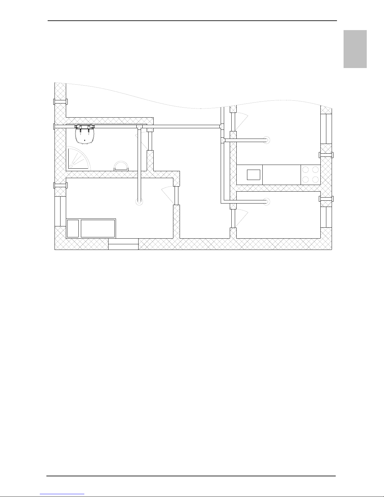
Models TC…ZNT
To make sure the operation of the pump is effective at all times, you can install
dampers to take air from the premises and then return it either to the premises or
utside. If the temperature of air is under -7 °C, heaters for the heating of domestic
water are switched on. The heat pump operates in reserve mode.
Fig. 5: Possible installation of a heat pump
EN
10
CONNECTION TO WATER SUPPLY MAINS
Water inlet and outlet on the heat pump are marked with colours. Cold water inlet is
marked with blue, and warm water outlet is marked with red. The heat pump is
designed for connection to indoor water supply mains without using the relief valve if
the pressure in the supply mains is lower than 0.6 MPa (6 bar). If the pressure is
higher, a relief valve needs to be installed so as to provide that the pressure at the
inlet to the hot water tank does not exceed the nominal pressure.
Installing a safety valve is mandatory in order to assure safe operation. The valve
prevents an increase of the pressure in the boiler by any more than 0.1 MPa (1 bar)
above the rated pressure. The outflow nozzle on the safety valve must have an outlet
into the atmosphere. To assure correct operation of the safety valve, the valve must
be regularly checked.
When checking the valve, push the lever or unscrew the nut of the valve (depending
on the type of the valve) and open the drain from the safety valve. Water must flow
from the valve nozzle, showing that the valve operation is faultless. During the
heating of water, the water pressure in the hot water tank is increased up to the level
preset in the safety valve. Since the system prevents backflow of water into the water
supply mains, water may be dripping from the outlet opening on the safety valve. The
dripping water may be drained via trap into the drains; the trap is mounted under the
safety valve. The outlet pipe, which is mounted under the safety valve, must be
directed downwards, in a place with a temperature above freezing.
If the installation does not allow draining of the water from the safety valve into the
drains, dripping can be avoided by installing an expansion vessel onto the heat pump
inlet pipe. The volume of the expansion vessel must be ca. 3% of the hot water tank
volume.
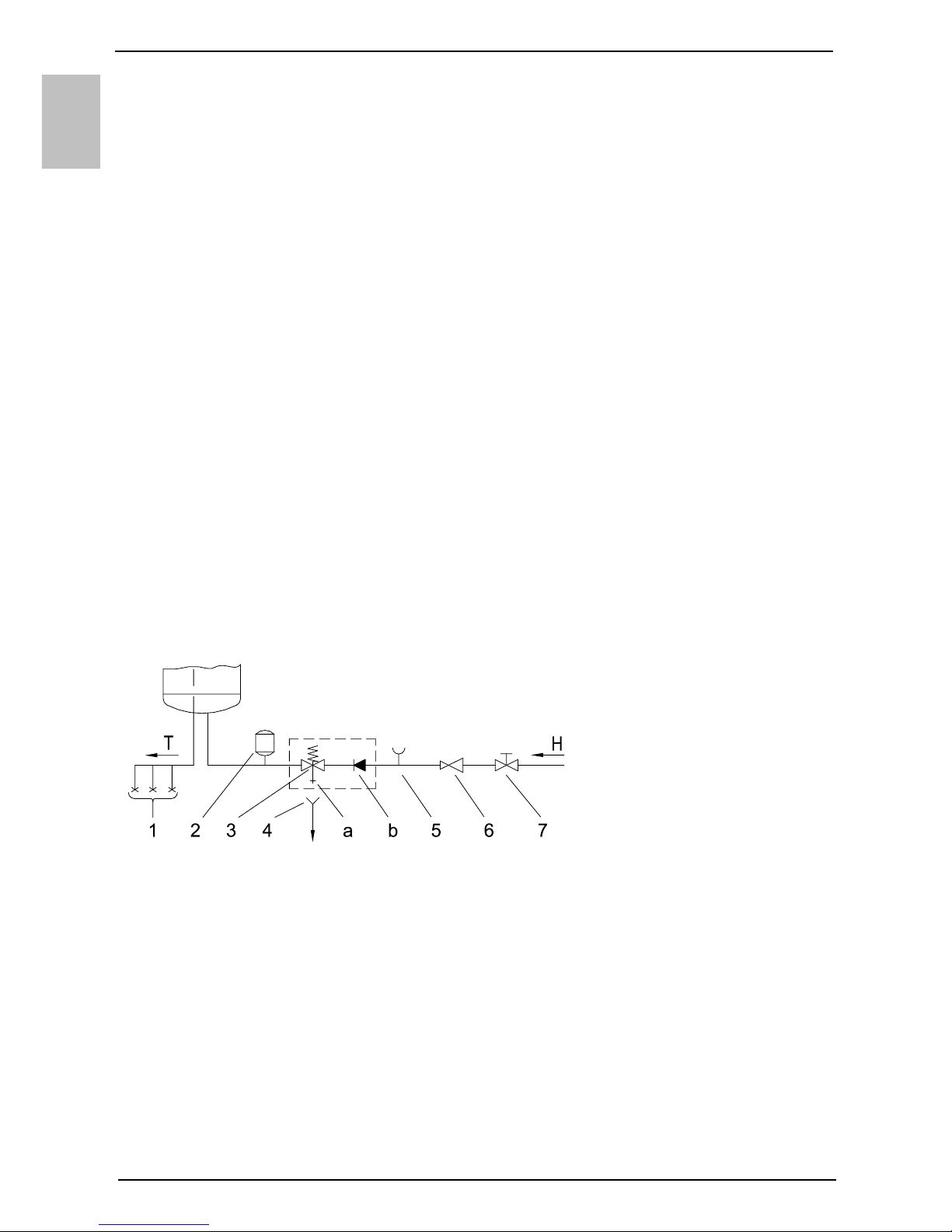
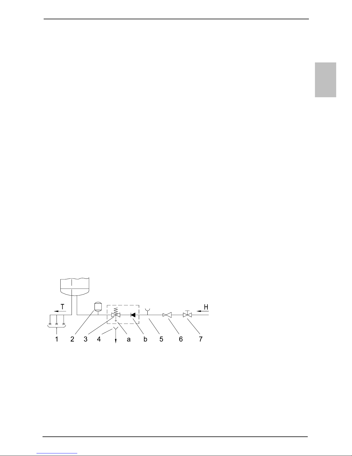
Fig. 6: Closed (pressure) system
Legend:
1 - Pressure mixer taps
2 - Expansion tank
3 - Safety valve
a - Test valve
b - Non-return valve
4 - Funnel with outlet connection
5 - Checking fitting
6 - Pressure reduction valve
7 - Closing valve
H - Cold water
T - Hot water
EN
11
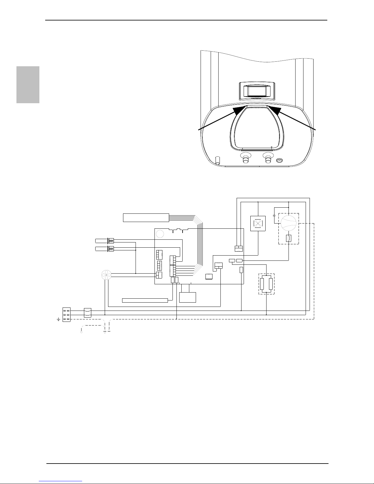
CONNECTING THE HEAT PUMP TO THE POWER SUPPLY NETWORK
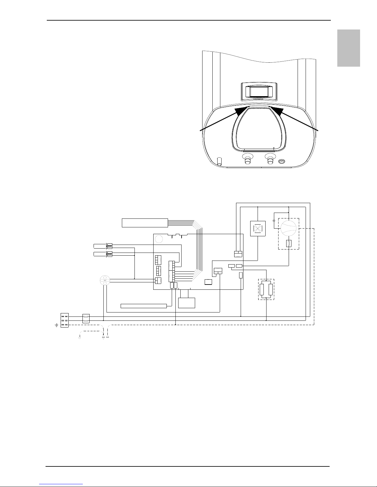
Before connecting to the power
supply network, install a power
supply cord in the heat pump, with a
min. diameter of 1.5 mm2 (H05VVF 3G 1.5 mm2). To do this, remove
the protective cover from the heat
pump. The cover is attached using
two screws (Fig. 7). Connecting the
heat pump to the power supply
network must take place in
accordance with the standards for
electric appliances. To comply with
the national installation regulations,
an all poles disconnect switch must
be installed between the heat pump
and the power supply network.
Fig. 8: Electrical circuit diagram
Legend:
QUART
PROG.
BUZZ1
K4
K9
K6
K5
K1
K11
K3
K10
K7
FAS5
FAS4
FAS1
FAS3 FAS2
8
7
4
T1
1000 W
6
1000 W
T2
T3
1
2
3
4
1
2
3
4
5
2
1
1
2 1
2
1 2
L
N
5
10
9
C
R
S
1
2
3
4
4
3
2
1
T1 - Bar with sensors
T2 - Evaporator – temp. sensor
T3 - Air temperature sensor
1 - 4-way valve
2 - Compressor
4 - Fan
5 - Electric heating element
(2 x 1000 W)
6 - Thermal cut-out
7 - Magnesium anode
8 - LCD touch screen
9 - Boiler - ground
10 - Housing - ground
Fig. 7: Protective cover
EN
12
HEAT PUMP OPERATION
The heat pump can be operated using an LCD touch screen (Fig. 9). If you press
anywhere on the screen, the screen lights up. When the screen is lit up, the operation
fields are active.
When the heat pump is connected to the water and power supply mains and the
boiler is filled with water, the heat pump is ready to be used. The heat pump heats
the water in the range 10 °C - 55 °C. From 55 °C - 75 °C the water is heated by
electrical heaters.
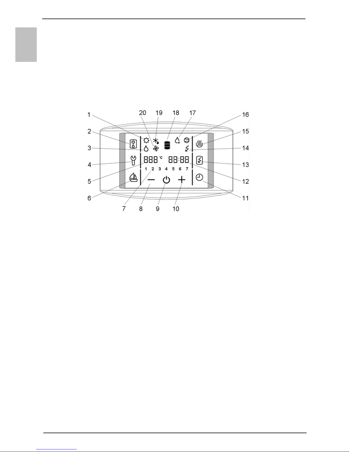
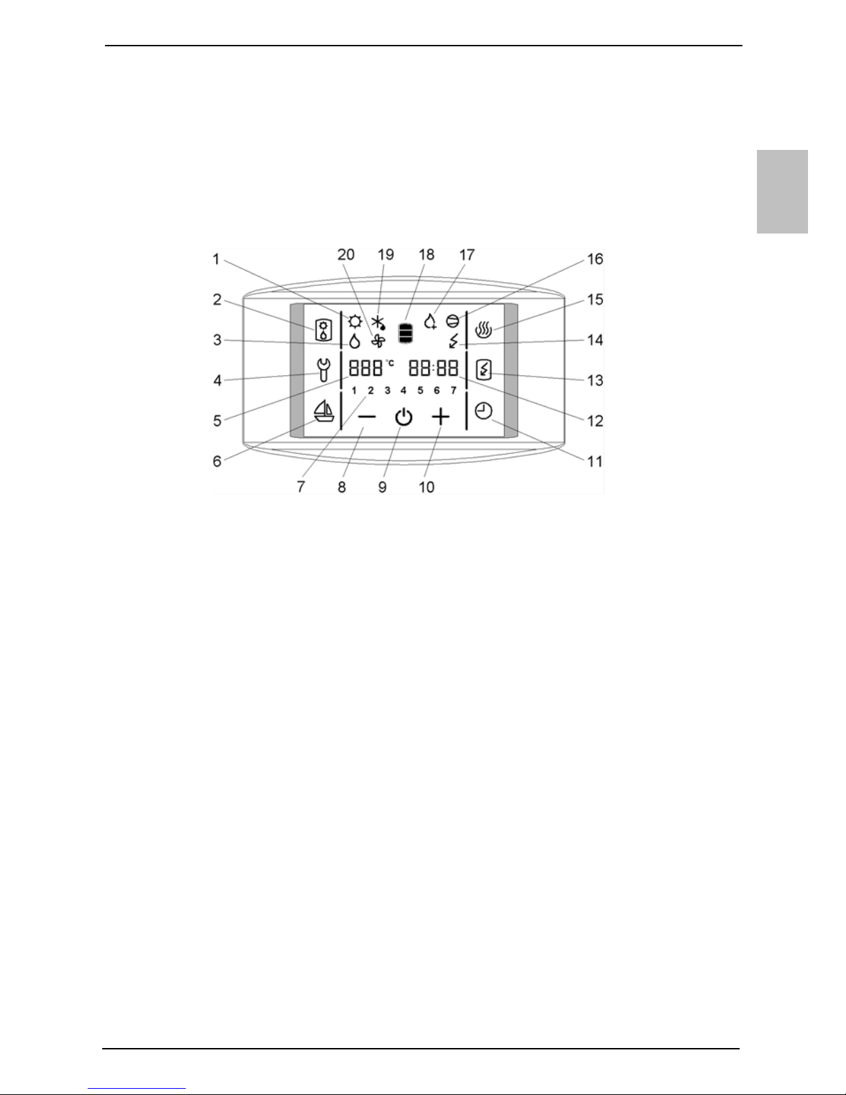
Fig. 9: LCD touch screen
Legend:
Starting/stopping the heat pump
To start the heat pump hold field no. 9.
When the appliance is switched on, the fan starts first and operates for one minute
(symbol no. 20 is displayed). If the temperature of inlet air is appropriate, the
1 - Signalization of the operation of solar
collectors**
2 - Alternative source of heating turned
on (heaters)
3 - Signalization of the operation of the
oil boiler**
4 - Indication, overview of operation
errors, entrance into the service
menu
5 - Display and setup of temperature
in °C
6 - Start and setup of the VACATION
programme
7 - Day of the week
(1 .. Monday, …, 7 .. Sunday)
8 - Reducing the value
9 - Heat pump on/off switch
10 - Increasing the value
11 - TIMER start and setup
12 - Time setup and display
13 - Start-up of quick heating "TURBO"
14 - Indicator of the heating element
operation
15 - Start-up of heating to the maximum
temperature level
16 - Signalization of compressor
operation
17 - Signalization of anti-legionella
programme operation
18 - Warm water quantity display
19 - Signalization of defrosting
20 - Signalization of fan operation
** function is not used in versions TC-Z,
TC-ZNT

EN
13
controlling unit switches on the compressor and the heat pump operates in normal
mode (symbols 16 and 20 are displayed). The heat pump is on, the screen remains
unlit and inactive.
In 60 seconds after the last touch of the screen, the illumination and activity of the
screen are turned off, but that does not affect the operation of the heat pump.
Pressing anywhere on the screen re-activates the screen and its illumination.
If trying to start up at a lower temperature, please see chapter "Operation at lower
temperatures".
By holding field no. 9, the heat pump is switched off. The appliance stops
functioning and the only field visible on the screen is field no. 9. (If you switch off
the heat pump for a longer period of time, the water must be drained from the pump
if there is any danger of freezing).
Power failure protection
In case of power failure, the settings remain stored for up to 23 hours.
After restarting, the heat pump operates in the same mode it was operating in before
the power failure.
Operation at lower temperatures
a) The ZNT version
When the appliance is switched on, the fan starts first and operates for one minute
(symbol no. 20 is displayed). If the temperature of inlet air is lower than -7 °C, the fan
is turned off. Domestic water is heated with heaters. The heat pump operates in the
reserve mode (symbol no. 14 is displayed). The possibility of switching to normal
mode is checked every 2 hours by switching on the fan for one minute. If the
temperature of inlet air is higher than -7 °C, the heat pump switches to normal mode
of operation (symbols 16 and 20 are displayed). The heaters switch off. The heat
pump is on, the screen remains unlit and inactive.
At lower air temperatures, the evaporator defrosting cycle is started if necessary.
Symbol no. 19 is displayed on the screen. The fields 2, 4, 6, 11, 13 and 15 remain
inactive. Defrosting takes place until the conditions for normal operation of the heat
pump are achieved.
After successful defrosting, the heat pump returns to normal operation (symbols 16
and 20 are displayed).
If defrosting is unsuccessful after two consecutive attempts, the controlling unit
displays an error message. Field no. 4 starts flashing, accompanied by warning
beeps. By pressing field no. 4 the warning beeps can be turned off. Error code E247
appears in field no. 12 and the pump switches automatically to heating with electric
heaters. The screen displays symbol no. 14. The error code can be deleted at any
time by pressing field no. 4. Field no. 12 resumes to displaying time.
b) The Z version
When the appliance is switched on, the fan starts first and operates for one minute
(symbol no. 20 is displayed). If the temperature of inlet air is lower than 7 °C, the fan
is turned off. Domestic water is heated with heaters. The heat pump operates in the
reserve mode (symbol no. 14 is displayed). The possibility of switching to normal
mode is checked every 2 hours by switching on the fan for one minute. If the

EN
14
temperature of inlet air is higher than 7 °C the heat pump switches to normal mode of
operation (symbols 16 and 20 are displayed). The heaters switch off. The heat pump
is on, the screen remains unlit and inactive.
Setting the clock and day of the week
Hold field no. 12, until field no. 7 shows a flashing number of the day of the week.
By pressing + or – you can set the number of the day of the week
(1 – Monday, …, 7 – Sunday).
Press field no. 12 again (flashing hour setting is displayed).
By pressing + or – set the hour (by holding + or – you can speed up the setting).
Press field no. 12 again.
Flashing minute setting is displayed.
By pressing + or – set the minutes (by holding + or – you can speed up the setting).
The setting is stored when you press field no. 12, or when the field stops flashing.
Setting the temperature
Press field no. 5 (the set temperature starts blinking).
By pressing + or – you can change the temperature setting from 10 °C to 75 °C
(preset to economic temperature of 55 °C).
The setting is stored by pressing field no. 5 again, or when field no. 5 stops
flashing. After a few seconds, the display shows the actual temperature.
In case of power failure, the last stored value is restored.
Switching on the "TURBO" mode
If you need more warm water than the heat pump can heat up in a short period of
time, press field no. 13 (switches on the "TURBO" mode). The heat pump and
heater work simultaneously. The screen shows symbols no. 14, 16 in 20. When the
temperature reaches 55 °C the heating pump returns to the mode used before the
"TURBO" mode.
Switching on the "HOT" mode
If you want to heat the water to the maximum temperature of 75 °C, press field no.
15. The heat pump will heat water to 55 °C. The screen displays symbols no. 16 in
20. When the temperature in the boiler reaches 55 °C the electric heater turns on to
heat the temperature up to 75 °C. The screen displays the symbol no. 14. When the
temperature reaches 75 °C the heating pump returns to the mode used before the
"HOT" mode.
Display of the quantity of water in the heat pump
The display shows the symbol: - no warm water
- low quantity of warm water
- high quantity of warm water

EN
15
Setting the vacation mode
In the vacation mode, you can set the number of days (maximally 100), when the
heat pump shall maintain the minimal temperature of water (approximately 10 °C).
Hold field no. 6 for a while (fields 5 and 6 start to flash).
By pressing fields + or – you can set the number of vacation days shown in field no.
5.
By pressing field no. 6 again, or when field no. 6 stops flashing, the set number of
days is stored.
If you set the value to 0, then the heat pump will resume its normal operating mode
after confirming the setting, and illumination of field no. 6 will turn off.
After the set number of days has elapsed, the heat pump returns to the normal
mode and illumination of field no. 6 turns off.
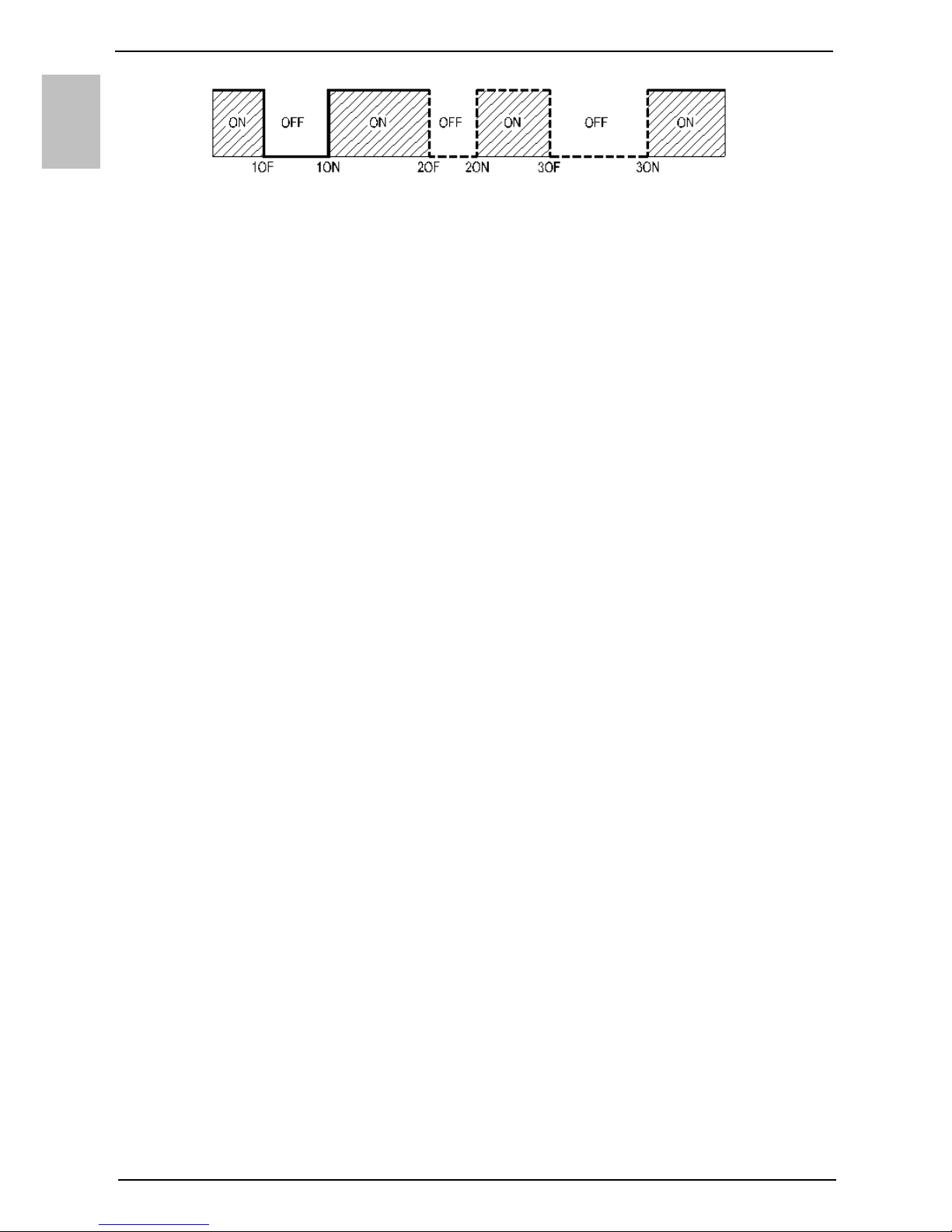
Setting the TIMER mode
In the TIMER operating mode, you can set the times when the heat pump will start
and stop. For each timer combination you can set up to three time periods in which
the heat pump will not heat the water.
a) Setting the timer combinations
Hold field no. 11 for a while (fields 7 and 11 start to flash).
By pressing fields + or – choose among three timer modes of operation:
- Timer mode of operation of the heat pump for the entire week (numbers 1-7 flash
in field no. 7),
- Timer mode of operation of the heat pump for Monday to Friday and Saturday to
Sunday (numbers 1-5 and then 6 and 7 flash in field no. 7),
- Timer mode of operation of the heat pump for each day at a time (individual
numbers 1-7 flash in field no. 7).
To set the time, press field no. 12.
On the field no. 5, the text 1OF appears and field no. 12 starts to blink.
By pressing fields + or – set the time of shutdown.
Press field no. 12 again.
On the field no. 5, the text 1ON appears and field no. 12 starts to blink.
By pressing fields + or – set the time of start-up.
By pressing field no. 12 again, you can use the above procedure to set the second
and third period.
By pressing field no. 12 again, or when field no. 6 stops flashing the set number of
days is stored. Again, press field no. 12.
b) Activation, deactivation of timer
By pressing field no. 11, you can activate the set timer mode.
The heat pump heats the water in the ON periods (to the set temperature) and in
the OFF periods, it does not heat the water.
By pressing field no. 11 again, you can deactivate the set time mode of operation.
EN
16
Fig. 10: Time periods
Anti-legionella function
Works only when the heat pump is switched on. When activated, symbol no. 17 is
displayed.
Automatic activation: every 2 weeks of operation of the heat pump, if the
temperature of water did not exceed 65 °C for one straight our or more in the
previous two-week period.
Anti-legionella programme can be activated manually by pressing field no. 15
(heating of water to the temperature of 75 °C).
Operation signalization:
Anti-legionella programme:
Programme on – control field no. 17 is displayed
Programme off – control field no. 17 is not displayed
electric heaters:
heaters on – control field no. 14 is displayed
heaters off – control field no. 14 is not displayed
heat pump:
heat pump is heating water – control field no. 16 is displayed
heat pump is not heating water – control field no. 16 is not displayed
on/off:
heat pump is on – next to field no. 9 other fields are also visible on the screen
heat pump is off – only field no. 9 is visible on the screen
defrosting:
heat pump is in the defrosting mode – control field no. 19 is displayed
heat pump is not in the defrosting mode – control field no. 19 is not displayed
fan on/off:
fan is on – control field no. 20 is displayed
fan is off – control field no. 20 is not displayed
alternative source of heat – electric heaters: (field no. 2)
switched to the electric heaters - control field no. 14 is displayed
fields 1 and 3 are not active in these versions of the heat pump
SERVICE AND MAINTENANCE
If installed and used correctly, the heat pump will last for years without service.
The exterior of the heat pump should be cleaned with a mild detergent solution. Do
not use solvents or abrasive cleaning agents.
If the heat pump was exposed to dust, evaporator lamellas might become blocked,
which can have a detrimental effect on the functioning of the heat pump. In this case
the evaporator should be cleaned. The cleaning of the evaporator must be carried out
by an authorised service provider.
EN
17
By providing regular service checkups, you can ensure flawless operation and long
life of the heat pump. The product is under warranty in accordance with the
conditions from the warranty statement.
Before calling your service provider, check the following:
Is everything OK with the power supply network?
Is the air outlet obstructed?
Is ambient temperature too low?
Can you hear the operation of the compressor and fan?
Pipeline system pressure drop
Do not try to eliminate malfunctions by yourself, call your nearest authorized
service provider!
OPERATION ERRORS
Despite careful production and control, the heating pump can produce errors that
must be solved by an authorised service provider.
Indicator of errors
In case of an error on the appliance, the beeper starts beeping and field no. 4 starts
flashing. When you press field no. 4 the error code is displayed in field no. 12.
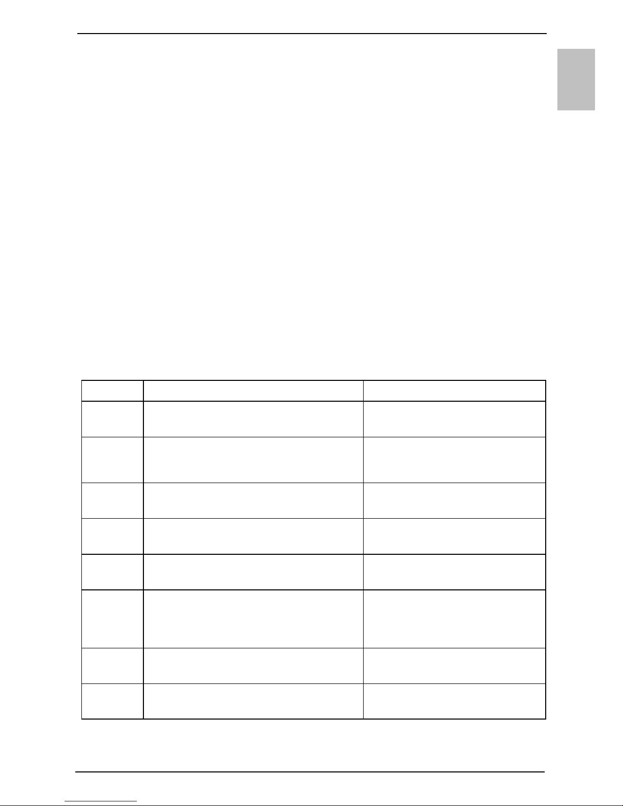
Error Description of error Solution
E004 Freezing. The error appears if the
temperature in the heat pump is below 4 °C.
Call the service.
E005 Overheating (temperature > 85 °C,
electronic regulator failure).
Unplug the heat pump from the
power supply. Call the service.
E006 Mg anode error. Call the service (heat pump
functions normally).
E007 Volume and/or temperature sensors error. Call the service.
E042 Anti-legionella function error. Press field no. 4 to restart.
E247 Defrosting error. Automatically turns on heating with
the electric heater. When the error
is deleted, the aggregate resumes
its normal operation.
E361 External air sensor error. Call the service (automatically
switches to the electric heater).
E363 Defrosting sensor error. Call the service (automatically
switches to the electric heater).
EN
18
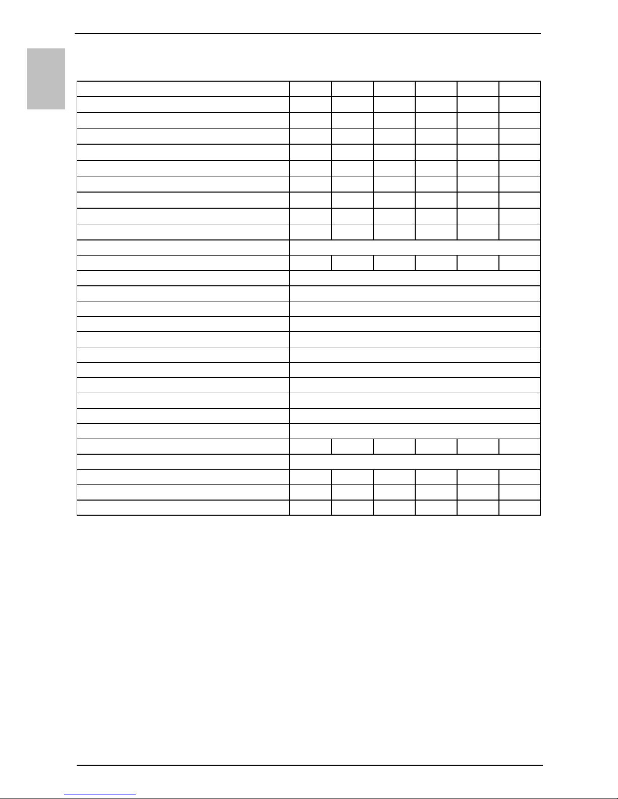
TECHNICAL CHARACTERISTICS
1) EU Regulation 812/2013; EN 50440
2) EN 50440
Type
TC80Z TC80ZNT TC100Z TC100ZNT TC120Z TC120ZNT
Declared load profile M M M M M M
Energy efficiency class (08/2017)
1)
A / (A+) A / (A+) A / (A+) A / (A+) A / (A+) A / (A+)
Water heating energy efficiency (ƞwh) 1) [%] 111,3 111,3 110,7 110,7 111,8 111,8
Annual electricity consumption 1) [kWh] 461 461 464 464 459 459
Daily electricity consumption 2) [kWh] 2,205 2,205 2,225 2,225 2,240 2,240
Thermostat temperature settings 55 55 55 55 55 55
Value of "smart" 0 0 0 0 0 0
Volume [l] 78,2 78,2 97,9 97,9 117,6 117,6
Quantity of mixed water at 40 °С V40 2) [l] 90 90 130 130 142 142
Rated pressure [MPa (bar)] 0,6 (6)
Weight / Filled with water [kg] 58 / 138 58 / 138 62 / 162 62 / 162 68 / 188 68 / 188
Anti-corrosion protection of tank Enamelled / MG Anode
Insulation thickness [mm] 40 - 85
Degree of protection IP24
Max connected load [W] 2350
Voltage 230 V / 50 Hz
Number and power of heating elements [W] 2 x 1000
Electricity protection [A] 16
Adjusted water temperature [°C] 55
Maximum temperature (HP / el. heater) [°C] 55 / 75
Legionella control programme [°C] 70
Temperature range of installation [°C] 2 to 35
Operation zone – air [°C] 7 to 35 -7 to 35 7 to 35 -7 to 35 7 to 35 -7 to 35
Refrigerating agent R 134a
Quantity of coolant [kg] 0,490 0,540 0,490 0,540 0,490 0,540
Global Warming Potential 1430 1430 1430 1430 1430 1430
Carbon dioxide equivalent [t] 0,700 0,772 0,700 0,772 0,700 0,772
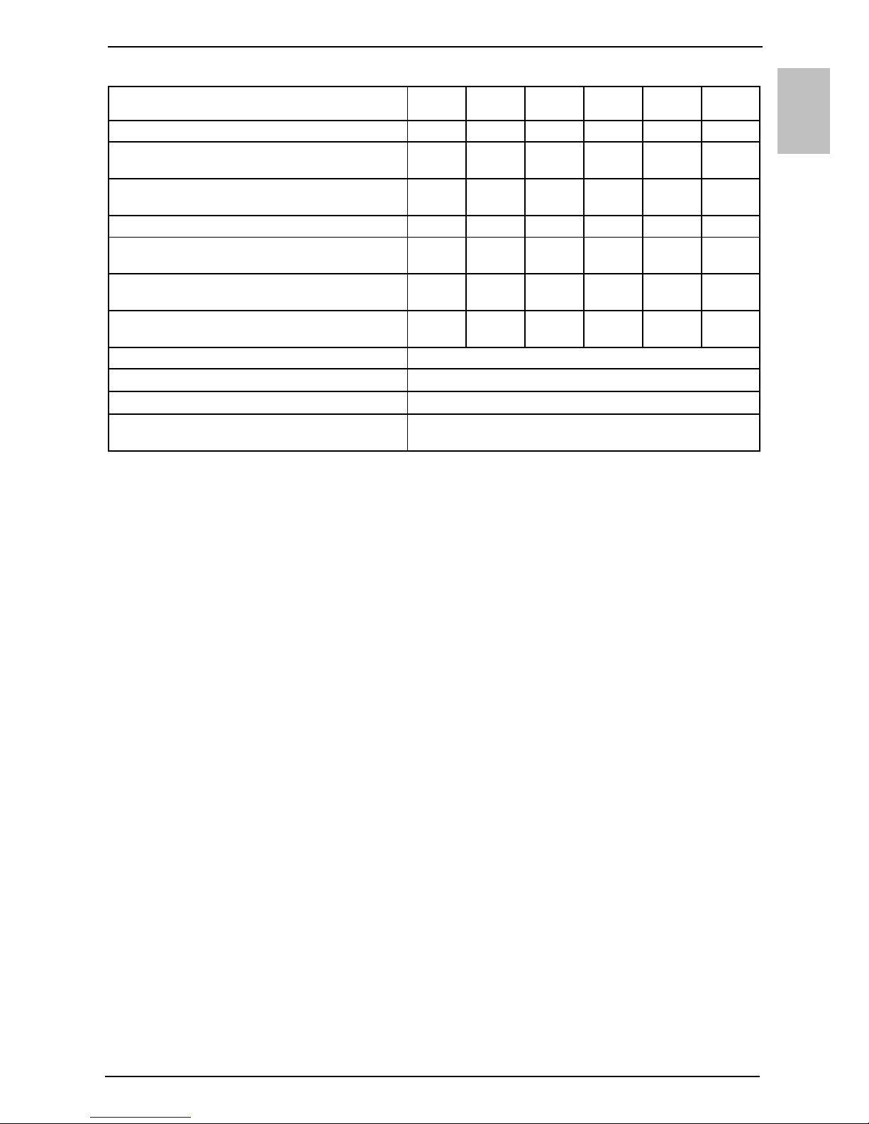
EN
19
(*) Heating of water to 55 °C at inlet air temperature of 15 °C, 74% humidity and inlet temperature of water of
10 °C; in accordance with the EN16147 standard.
(**) Heating of water to 55 °C at inlet air temperature of 7 °C, 89% humidity and inlet temperature of water of
10 °C; in accordance with the EN16147 standard.
WE RESERVE THE RIGHT TO ANY MODIFICATIONS NOT AFFECTING THE
FUNCTIONALITY OF THE APPLIANCE.
Type
TC80Z TC80ZNT TC100Z TC100ZNT TC120Z TC120ZNT
*Heating time A15 / W10-55 [h:min] 4:40 4:40 5:40 5:40 6:40 6:40
*Energy consumption in the selected cycle
of emissions A15 / W10-55 [kWh]
2,04 2,04 2,05 2,05 2,08 2,08
*COP
DHW
in the selected cycle of emissions
A15 / W10-55
3,10 3,10 3,10 3,10 3,10 3,10
**Heating time A7 / W10-55 [h:min] 5:20 5:20 6:50 6:50 8:41 8:41
**Energy consumption in the selected cycle of
emissions A7 / W10-55 [kWh]
2,45 2,45 2,35 2,35 2,51 2,51
**COP
DHW
in the selected cycle of emissions
A7 / W10-55
2,65 2,65 2,63 2,63 2,61 2,61
Power in standby mode
according to EN16147 [W]
19 19 20 20 27 27
Sound power / Sound pressure at 1m [dB(A)] 51 / 39,5
Air connections [mm/m]
ø125 (□150x70) / 10
Working Air Flow [m3/h] 100-230
Max acceptable pressure drop in the pipeline
(volumetric flow rate of air 150 m3/h) [Pa]
90
DE
20
HINWEISE!
Das Gerät kann von 8-jährigen und älteren Kindern und Personen mit
begrenzten physischen, sinnlichen und psychischen Fähigkeiten oder mit
ungenügend Erfahrungen bzw. Kenntnis benutzt werden, falls sie dabei
kontrolliert werden oder über die sichere Anwendung des Gerätes belehrt
worden sind und dass sie die eventuelle damit verbundene Gefahr verstehen.
Kinder dürfen mit dem Gerät nicht spielen.
Kinder dürfen das Gerät nicht reinigen oder warten, wenn sie dabei nicht
von einer befähigten Person kontrolliert werden.
Die Wärmepumpe darf nur in senkrechter Lage transportiert werden,
ausnahmsweise darf sie um 35° in jede Richtung geneigt werden.
Die Wärmepumpe ist nicht für die industrielle Anwendung und Anwendung
in den Räumen mit vorhandenen Korrosions- und Explosionsstoffe bestimmt.
Der Anschluss der Wärmepumpe ans Stromnetz ist im Einklang mit den
Standards für elektrische Installation auszuführen. Zwischen Wärmepumpe
und Dauerinstallation ist ein Pole-Trennelement nach nationalen
Installationsvorschriften einzubauen.
Die Wärmepumpe darf bei leerem Kessel (kein Wasser im Kessel) nicht im
Betrieb sein, damit kein Schaden am Aggregat entstehen kann!
Die Installation ist nach den gültigen Vorschriften und nach Anweisungen
des Herstellers auszuführen. Die Installation darf nur ein fachlich ausgebildeter
Installateur ausführen.
Auf das Zuflussrohr der Wärmepumpe ist unbedingt ein Sicherheitsventil
mit Nenndruck 0,6 MPa (6 Bar) zu installieren, um die Druckerhöhung im Kessel
um mehr als 0,1 MPa (1 bar) über den Nenndruck zu verhindern.
Das Wasser kann aus der Abflussöffnung des Sicherheitsventils tropfen,
deshalb muss die Zuflussöffnung auf Atmosphärendruck geöffnet sein.
Der nach unten gerichtete Auslass des Sicherheitsventils darf in keiner
Frostumgebung installieren werden.
Die einwandfreie Funktion des Sicherheitsventils müssen Sie selber
regelmäßig kontrollieren. Sie müssen den Kalk entfernen und das
Sicherheitsventil auf Blockade zu prüfen.
Zwischen Wärmepumpe und Sicherheitsventil darf kein Schliessventil
installiert werden, so dass die Funktion des Sicherheitsventils nicht blockiert
wird!
Vor dem Betrieb sind auf die Kappe des Gerätes unbedingt zwei Bögen 90°
(ø125 mm), jeder in eigene Richtung, anzubringen. Der Raum muss gut gelüftet
werden.
Die Elemente in der elektronischen Steuerungseinheit sind auch nach der
Betätigung des Ausschaltfeldes (9) der Wärmepumpe unter Spannung.
Falls Sie die Wärmepumpe ausschalten (vom Stromnetz nehmen), müssen
Sie das Wasser wegen Frostgefahr aus der Wärmepumpe ablassen.
Das Wasser aus der Pumpe wird durch das Zuflussrohr des Kessels
abgelassen. Es ist sinnvoll zwischen Sicherheitsventil und Zuflussrohr ein
Spezialteil oder ein Auslassventil zu installieren.
DE
21
Wir bitten Sie, eventuelle Störungen an der Wärmepumpe nicht selber zu
reparieren, sondern nehmen Sie beim nächsten beauftragten Kundendienst
Kontakt auf.
Dieses Produkt enthält fluorierte Treibhausgase. Hermetisch abgedichtet.
Unsere Produkte bestehen aus den umgebungs- und
gesundheitsfreundlichen Bauteilen. Die entsprechende Bauweise der
Produkte ermöglicht, dass sie am Ende der Lebensdauer einfach
demontiert und rezykliert werden können.
Durch die Rezyklierung der Materialien werden die Menge der Abfälle
und der Bedarf an der Produktion der Grundstoffe (z.B. Metalle) mit enormem
Energieverbrauch und erheblicher Emission der Schadstoffe vermindert.
Folglich werden auch die natürlichen Ressourcen bewahrt, denn die Abfallteile
aus Kunststoff und Metall können in den verschiedenen Produktionsverfahren
wieder verwendet werden.
Für mehr Informationen über das System der Abfallbeseitigung fragen Sie Ihr
Zentrum zur Entsorgung von Abfällen oder den Verkäufer, bei welchem Sie das
Produkt gekauft haben.
VORSTELLUNG
Verehrte Kundin, verehrter Kunde!
Wir danken Ihnen, dass Sie sich für den Kauf unserer Brauchwasser-Wärmepumpe
Gorenje entschieden haben. Damit haben Sie Ihr Vertrauen einem der
technisch ausgeklügelten Geräte erwiesen. Werkstoffe, Konstruktion und Prüfungen
sind mit den Normen abgestimmt, die diesen Bereich betreffen.
Leistung, Kapazität und Sicherheitsvorrichtungen wurden in unseren Labors geprüft.
Alle Prüfungen an den Bauteilen und am Endprodukt wurden in Einklang mit den
internationalen Normen des Qualitätsstandards durchgeführt.
Lesen Sie bitte sorgfältig die Bedienungsanleitung, die Informationen über die
Funktion sowie die Hinweise zur Instandhaltung; dadurch können Sie
Unannehmlichkeiten und Schäden am Gerät verhindern.
Bewahren Sie dieses Handbuch sorgfältig auf, damit Sie es zur Hand nehmen
können, wenn Sie Zweifel bezüglich der Funktion oder Instandhaltung haben sollten.
Die Installations- und Wartungsanleitungen finden Sie auch auf unseren Webseiten
http://www.gorenje.com .
Sie können auch jederzeit den autorisierten Kundendienst für gelegentliche
Instandhaltungsarbeiten anrufen. Unsere Kundendienst-Fachleute stehen Ihnen
gerne mit Ihren Erfahrungen zur Verfügung.

DE
22
ANWENDUNGSGEBIET
Dieses Gerät ist zur Warmwasserbereitung im Haushalt und bei anderen
Verbrauchern mit einem täglichen Warmwasserverbrauch (40° C) von 150 l bis 250 l
bestimmt. Das Gerät ist an die hauseigene Installation des warmen Brauchwassers
und ans elektrische Versorgungsnetz angeschlossen. Die zur Funktion des Geräts
notwendige Luftansaugung und -abgabe kann auch aus einem anderen Raum
ausgeführt werden.
Falls Sie die Wärmepumpe in einem Raum aufstellen, in dem sich eine Badewanne
oder Duschkabine befindet, sind unbedingt die Anforderungen des Standards IEC
60364-7-701 (VDE 0100, Teil 701) zu berücksichtigen. Das Gerät ist ausschließlich
für die senkrechte Wandmontage mit Wandschrauben, Nominaldurchmesser
Minimum 8 mm bestimmt. Eine Wand mit schlechter Tragfähigkeit muss an der
Montagestelle entsprechend verstärkt werden. Zur leichten Kontrolle und zum
Wechseln der Mg-Schutzanode ist es sinnvoll, genügend Raum zwischen Gerät und
Boden zu lassen, sonst muss das Gerät beim Serviceeingriff von der Wand
demontiert werden (Bild 4).
Ein andersartiger Gebrauch des Geräts als der angeführte ist nicht erlaubt. Das
Gerät ist nicht zum Gebrauch in der Industrie oder in Räumen bestimmt, in welchen
korrosive und explosive Stoffe vorhanden sind.
Der Hersteller haftet nicht für Schäden, die wegen unsachgemäßem Einbau und
Gebrauch entstehen und nicht in Einklang mit der Montage- und
Bedienungsanleitung sind.
Die Bedienungsanleitung ist ein wichtiger Bestandteil des Produkts und muss
dem Käufer ausgehändigt werden. Der Käufer sollte die Hinweise in der
Bedienungsanleitung sorgfältig lesen, weil darin wichtige Hinweise über die
Sicherheit bei Installation, Gebrauch und Instandhaltung angeführt sind.
Die Bedienungsanleitung ist sorgfältig für eventuelle künftige Verwendung
aufzubewahren.
Der Typ Ihrer Wärmepumpe ist auf dem Typenschild angegeben, das an der
Unterseite des Geräts zwischen den Anschlussrohren für Brauchwasser angebracht
ist.
Überprüfen Sie nach der Entfernung der Verpackung deren Inhalt. Wenden Sie sich
im Zweifelsfall an Ihren Lieferanten. Lassen Sie Verpackungsteile (Klammern, PVCSäcke, Styropor u.Ä.) nicht im Zugriffsbereich von Kindern liegen, weil diese
potentielle Gefahrenquellen darstellen. Sorgen Sie für eine umweltgerechte
Entsorgung der Verpackung.
LAGERUNG UND TRANSPORT
Die Wärmepumpe darf nur in senkrechter Lage gelagert werden und zwar in einem
trockenen und sauberen Raum.
DE
23
FUNKTIONSPRINZIP DER WÄRMEPUMPE
Die Wärmepumpe ist ein thermodynamischer Wärmegenerator, der die Wärme aus
dem niedrigeren Temperaturniveau (z.B. Wärme der Raumluft) auf ein höheres
Temperaturniveau anhebt (z.B. warmes Brauchwasser).
Diese, der Raumluft entzogene Wärme, schafft zusammen mit der Antriebsenergie
(elektrische Energie) Wärmeenergie, die zum Erwärmen des Brauchwassers zur
Verfügung steht.
Bild 1: Schematische Darstellung des Energieflusses durch das Aggregat der Wärmepumpe
DIMENSIONEN
* - DIN Norm
** - NF Norm
Bild 2: Anschluss- und Installationsmaße der Wärmepumpe (mm)
A B C * C ** D * D ** E * E **
TC 80
1197 345 100 175 100 230 G 1/2 G 3/4
TC 100
1342 490 100 175 100 230 G 1/2 G 3/4
TC 120
1497 645 100 175 100 230 G 1/2 G 3/4
A
264
B
589
C
294
350
350
D
E
324
506
533
285
170
DE
24
AUFSTELLUNG DER WÄRMEPUMPE
Die Wärmepumpe kann mit Raumluft oder gesteuerter Luft arbeiten. Der Raum, in
dem die Wärmepumpe betrieben wird, muss frostfrei sein. Besonders ist darauf zu
achten, dass eine möglichst verunreinigungsfreie Luftaufnahme gewährleistet wird.
Der Staub schadet der Effizienz der Wärmepumpe.
Bei der Auswahl des Aufstellungsortes müssen Sie berücksichtigen, dass die Wand
für das Gewicht der Wärmepumpe samt Brauchwasser entsprechend tragfähig ist.
Treffen Sie Maßnahmen, welche die Betriebsgeräusche und Vibrationen des Geräts
nicht über Wände auf Schlafzimmer oder andere zur Entspannung bestimmten
Räume übertragen. Stellen Sie die Wärmepumpe und die Zuluftanschlüsse nicht im
selben Raum auf, in welchem sich noch andere Luftverbraucher (Gaskessel,
Feststofföfen, Absauganlagen, u.Ä.) befinden. Berücksichtigen Sie bei der
Aufstellung des Geräts die Minimalabstände zur Wand, zum Boden und zur Decke.
Die Kondenswasserableitung der Wärmepumpe ist an der unteren linken Seite mit
einem Kunststoffröhrchen von 18 mm Durchmesser ausgeführt. Mit diesem Röhrchen
müssen Sie das Außenrohr für die Ableitung des Kondenswassers verbinden und in
einen Abfluss oder Behälter einleiten. Die Menge des Kondenswassers ist von der
Temperatur und Feuchtigkeit der Luft während Betrieb der Wärmepumpe abhängig.
Damit im Gebäude kein Unterdruck
entsteht, muss frische Luft
kontrolliert in die Räume zugeführt
werden. Die gewünschte Stufe der
Luftwechsel für ein Wohngebäude
beträgt 0,5. Das bedeutet, dass die
gesamte Luftmenge im Gebäude alle
zwei Stunden gewechselt wird.
Der Anschluss der Wärmepumpe in
die gleiche Rohrleitung mit der
Dunstabzugshaube und die
Luftabfuhr aus mehreren kleineren
Wohnungen oder Appartements ist
nicht erlaubt.
Bild 3: Belüftung
Zur Lärm- und Vibrationsminderung durch die Wände in Räume, wie Schlafräume,
Erholungsräume sind folgende Vorkehrungen zu berücksichtigen:
- Einbau von flexiblen Verbindungen für die hydraulischen Anschlüsse
- Einbau des flexiblen Rohrs für die Rohrleitung Ab-/Zuluft
- Schwingungsisolation für die Wand-Absaugöffnung
- Schalldämpfer von Ab-/Zuluft vorsehen
- Rohrleitungen für Ab-/Zuluft befestigen Sie mit Schwingungsisolation
- Schwingungsisolation gegen die Wand vorsehen
DE
25
a) Betrieb mit Raumluft
Beim Betrieb mit Raumluft wird für das
Erwärmen des Brauchwassers nur die
Energiemenge der Luft im Aufstellungsort
benutzt. Die Wärmepumpe ist in einem
luftigen und frostfreiem Raum, falls möglich in
der Nähe von anderen Heizquellen zu
installieren. Die optimale Leistung der
Wärmepumpe kann in einem entsprechend
großen und luftigen Raum mit
Raumtemperatur zwischen 15 °C und 25 °C
erreicht werden. Die Luftzufuhr in den Raum
muss ausreichend sein. Auf die
Wärmepumpe sind Kniestücke anzubringen
und so zu richten, dass die Luftmischung
verhindert wird. Die Wärmeverluste im Raum
mit kalter Luft sind größer.
Modelle TC…Z
Soll die Wärmepumpe in einem frostfreien
Raum stehen und die Temperatur fällt unter
7 °C, schalten zum Erwärmen des
Brauchwassers die Heizkörper ein. Die
Wärmepumpe arbeitet im Ersatzbetrieb.
Modelle TC…ZNT
Soll die Wärmepumpe in einem frostfreien
Raum stehen und die Temperatur fällt unter
7 °C, arbeitet die Wärmepumpe im
Normalbetrieb.
b) Betrieb mit gesteuerter Luft
Beim Betrieb mit gesteuerter Luft erfolgt die Luftzufuhr, bzw. –abfuhr über die
Rohrleitung auch von anderen Stellen. Die Wärmeisolierung der Rohrleitung ist
sinnvoll, um die Kondensatbildung zu verhindern. Bei Luftaufnahme von Außen ist
der Außenteil entsprechend zu decken, dass kein Staub oder Schnee in das Gerät
gelangen. Durch den vergrößerten Luftwiderstand in den Rohren und Kniestücken
steigt auch der Betriebsgeräuschpegel an.
Bei der Ausführung mit gesteuerter Luft sind die minimalen zugelassenen
Rohrdurchmesser ø125 mm oder □150x70 zu berücksichtigen. Die Anleitungen für
das Projektieren des Rohrleitungssystems finden Sie auf unseren Webseiten
http://www.gorenje.com .
Modelle TC…Z
Um den einwandfreien Betrieb der Wärmepumpe zu gewährleisten soll die
Temperatur der aufgenommenen Außenluft immer höher als 7 °C sein. Um ständig
eine wirkungsvolle Leistung der Wärmepumpe zu gewährleisten, können Sie die
Richtungsklappen installieren. Sie nehmen die Luft aus dem Raum auf und führen sie
dann wieder zurück in den Raum oder nach Außen. Wird die Temperatur der
aufgenommenen Luft niedriger als 7 °C sein, werden für das Erwärmen des
min 25 cmmin 25 cm
min 150 cm
min 20 cm
min 75 cm
Bild 4: Minimale Anforderungen für
die Aufstellung der Wärmepumpe
DE
26
Brauchwassers die Heizkörper eingeschaltet. Die Wärmepumpe arbeitet im
Ersatzbetrieb.
Modelle TC…ZNT
Um ständig eine wirkungsvolle Leistung der Wärmepumpe zu gewährleisten, können
Sie die Richtungsklappen installieren. Sie nehmen die Luft aus dem Raum oder vom
Außen auf und führen sie dann wieder zurück in den Raum oder nach Außen. Wird
die Temperatur der aufgenommenen Luft niedriger als 7 °C sein, werden für das
Erwärmen des Brauchwassers die Heizkörper eingeschaltet. Die Wärmepumpe
arbeitet im Ersatzbetrieb.
Bild 5: Variante für die Aufstellung der Wärmepumpe
DE
27
ANSCHLUSS AN DAS WASSERVERSORGUNGSNETZ
Das Wasserzuflußrohr der Wärmepumpe (Kaltes Wasser) trägt blaue Kennzeichnung
und das Wasserabflussrohr (warmes Wasser) trägt rote Kennzeichnung. Sie können
die Wärmepumpe an das hauseigene Wasserversorgungsnetz ohne Druckminderventil
anschließen, wenn der Druck im Netz niedriger ist als 0,6 MPa (6 bar). Im Gegenfall ist
der Einbau eines Druckminderventils notwendig, welches gewährleistet, dass der
Druck am Zufluss in den Warmwasserspeicher den Nenndruck nicht übersteigt.
An das Zuflussrohr ist wegen der Betriebssicherheit unbedingt ein Sicherheitsventil
einzubauen, welches den Druckanstieg im Kessel um mehr als 0,1 MPa (1 bar) über
dem Nenndruck verhindert. Die Abflussdüse auf dem Sicherheitsventil muss unbedingt
einen Ausgang zum atmosphärischen Druck besitzen. Zur ordnungsgemäßen Funktion
des Sicherheitsventils müssen Sie selbst regelmäßige Kontrollen durchführen.
Bei der Prüfung müssen Sie durch Betätigung des Hebels oder Lösen der Ventilmutter
(abhängig vom Ventiltyp) den Ablass des Sicherheitsventils öffnen. Dabei muss durch
die Ablassdüse des Ventils Wasser fließen, was ein Zeichen dafür ist, dass das Ventil
störungsfrei arbeitet.
Beim Erwärmen des Wassers erhöht sich der Druck im Warmwasserspeicher bis zum
Grenzwert, der auf dem Sicherheitsventil eingestellt ist. Da die Rückführung des
Wassers in das Wasserversorgungsnetz verhindert ist, kann es zum Tropfen des
Wassers aus der Ablassöffnung des Sicherheitsventils kommen. Das tropfende
Wasser können Sie über den Auffangstutzen in den Abfluss ableiten, welchen Sie
unter das Sicherheitsventil montieren. Das unter dem Ablass des Sicherheitsventils
montierte Abflussrohr muss in Richtung gerade nach unten montiert werden und zwar
in einer Umgebung, wo es keinen Frost gibt.
Falls Sie wegen unzutreffender Installation keine Möglichkeit haben, das tropfende
Wasser aus dem Sicherheitsventil in den Abfluss abzuleiten, können Sie das Tropfen
verhindern, indem Sie einen geeigneten Expansionsbehälter am Zuflussrohr des
Heizelements anschließen. Das Volumen des Expansionsbehälters muss ca. 3% des
Volumens des Warmwasserspeichers betragen.
Bild 6: Geschlossenes System (druckfestes System)
Legende:
1 - Druckmischbatterien
2 - Expansionsgefäß
3 - Sicherheitsventil
a - Ablaufrohr
b - Rückflussstopp
4 - Ablaufsiphon
5 - Prüfstutzen
6 - Druckminderer
7 - Absperrventil
H - Kaltwasser
T - Warmwasser
DE
28
ELEKTRISCHER ANSCHLUSS
Vor dem standardmäßigem Anschließen
ans Elektronetz ist in die Wärmepumpe
ein Anschlusskabel mit minimalem
Durchmesser von mindestens 1,5 mm2
(H05VV-F 3G 1,5 mm2) zu installieren. Sie
müssen dazu den mit zwei Schrauben
(Bild 7) befestigten Schutzdeckel
abnehmen. Zwischen Wärmepumpe und
Dauerinstallation ist die Trennvorrichtung
für alle Pole vom Elektronetz nach
nationalen Installationsvorschriften
auszuführen.
Bild 8: Elektroschaltbild
Legende:
QUART
PROG.
BUZZ1
K4
K9
K6
K5
K1
K11
K3
K10
K7
FAS5
FAS4
FAS1
FAS3 FAS2
8
7
4
T1
1000 W
6
1000 W
T2
T3
1
2
3
4
1
2
3
4
5
2
1
1
2 1
2
1 2
L
N
5
10
9
C
R
S
1
2
3
4
4
3
2
1
T1 - Fühler-Leiste
T2 - Temperatursensor Verdampfer
T3 - Lufttemperatur-Sensor
1 - 4-Wegventil
2 - Kompressor
4 - Ventilator
5 - Heizkörper (2 x 1000 W)
6 - Wärmesicherung
7 - Magnesium-Anode
8 - LCD Display
9 - Kesselerdung
10 - Gehäuseerdung
Bild 7: Schutzdeckel
DE
29
BEDIENUNG DER WÄRMEPUMPE
Die Wärmepumpe wird über das LCD Betätigungsdisplay (Bild 9) bedient. Durch
Berühren einer beliebigen Stelle leuchtet das Display auf und die Bedienfelder
werden aktiv. Die Wärmepumpe ist nach dem Anschluss der an das Wasserleitungsund Elektronetz und mit Wasser gefülltem Kessel, betriebsbereit. Die Wärmepumpe
erwärmt das Wasser im Temperaturbereich von 10 °C bis 55 °C, von 55 °C bis 75 °C.
Das Wasser wird von elektrischen Heizkörpern erwärmt.
Bild 9: Bedienungsdisplay
Legende:
Ein-/ Ausschalten der Wärmepumpe
Einschalten: Betätigen Sie das Feld 9.
Beim Starten der Anlage wird zuerst der Ventilator eingeschaltet und er arbeitet 1
Minute (das Symbol 20 ist sichtbar). Ist die Zuluft-Temperatur in Ordnung, schaltet
1 - Signalisierung der Funktion der
Solarkollektoren**
2 - Einschaltung der alternativen
Heizquelle (Heizkörper)
3 - Signalisierung der Funktion des
Ölkessel**
4 - Indikation, Kontrolle der
Betriebsstörungen, Eingabetaste für
Servicemenü
5 - Anzeige und Einstellung der
Temperatur in °C
6 - Einschaltung und Einstellung der
Betriebsart URLAUB
7 - Anzeige des Wochentages
(1 .. Montag, …, 7 .. Sonntag)
8 - Reduzieren des Wertes
9 - Ein- /Ausschaltung der
Wärmepumpe
10 - Erhöhung des Wertes
11 - Einschaltung und Einstellung der
Zeitbetriebsarten
12 - Anzeige und Einstellung der Zeit
13 - Einschaltung der beschleunigten
Heizung "TURBO"
14 - Anzeige des Heizkörperbetriebes
15 - Einschaltung der Heizung auf das
maximale Temperaturniveau
16 - Signalisierung der Funktion des
Kompressors
17 - Signalisierung der
Antilegionellenfunktion
18 - Anzeige Warmwassermenge
19 - Signalisierung des Abtauens
20 - Signalisierung der Funktion des
Ventilators
** in Ausführungen TC-Z, TC-ZNT nicht
verfügbar

DE
30
die Steuerung noch den Kompressor ein und die Wärmepumpe arbeitet in normaler
Betriebsart (die Symbole 16 und 20 sind sichtbar). Die Wärmepumpe ist
eingeschaltet, der Bildschirm ist nicht beleuchtet und nicht aktiv.
60 Sekunden nach letzter Betätigung einer beliebigen Stelle des Bildschirms,
schalten die Beleuchtung und die Aktivität des Bildschirms aus, was aber die
Funktion der Wärmepumpe nicht beeinträchtigt. Die erste beliebige Betätigung des
Bildschirms aktiviert den Bildschirm und dessen Beleuchtung wieder.
Bei der Einschaltung von niedrigeren Temperaturen siehe das Kapitel "Arbeiten bei
niedrigen Temperaturen".
Mit längerer Betätigung des Feldes 9 schalten Sie die Wärmepumpe aus. Die
Anlage arbeitet nicht mehr, auf dem Bildschirm wird nur das Feld 9 gezeigt. (Falls
die Wärmepumpe längere Zeit ausgeschaltet wird, ist das Wasser wegen
Frostgefahr abzulassen).
Schutz beim Stromausfall
Beim Stromausfall bleiben die Einstellparameter 23 Stunden erhalten.
Bei erneuter Inbetriebnahme arbeitet die Wärmepumpe in gleicher Betriebsart wie vor
dem Stromausfall.
Betrieb bei niedrigen Temperaturen
a) Ausführung ZNT
Bei Inbetriebnahme der Anlage wird zuerst der Ventilator eingeschaltet und er
arbeitet 1 Minute (das Symbol 20 ist sichtbar). Ist die Zuluft-Temperatur niedriger als
-7 °C, schaltet der Ventilator aus. Zum Erwärmen des Brauchwassers werden die
Heizkörper eingeschaltet. Die Wärmepumpe arbeitet im Ersatzbetrieb (das Symbol
14 ist sichtbar). Vor Umschaltung in die normale Betriebsart wird die Funktion des
Ventilators alle 2 Stunden 1 Minute lang geprüft. Ist die Zuluft-Temperatur höher als 7 °C, beginnt die Wärmepumpe in normaler Betriebsart zu arbeiten (die Symbole 16
und 20 sind sichtbar). Die Heizkörper schalten aus. Die Wärmepumpe ist
eingeschaltet, der Bildschirm ist nicht beleuchtet und nicht aktiv.
Bei niedrigen Temperaturen wird nach Bedarf der Abtau-Zyklus des Verdampfers
aktiviert. Auf dem Bildschirm ist das Symbol 19 sichtbar. Die Felder 2, 4, 6, 11, 13
und 15 sind nicht aktiv. Das Abtauen dauert so lange bis Bedingungen für die
normale Betriebsart der Wärmepumpe herrschen.
Nach erfolgreich beendetem Abtauen befindet sich die Wärmepumpe wieder in
normaler Betriebsart (die Symbole 16 und 20 sind sichtbar).
Falls das Abtauen nach zwei Versuchen nicht erfolgreich war, erscheint die
Fehlermeldung. Das Feld 4 auf dem Bildschirm beginnt zu blinken und Alarmsignale
sind hörbar. Die Warnpfeiftöne schalten Sie mit der Betätigung des Feldes 4 aus. Im
Feld 12 wird der Fehlerkode E247 gezeigt, es kommt zur automatischen
Umschaltung auf die Heizung mit elektrischen Heizkörpern. Auf dem Bildschirm
erscheint das Symbol 14. Den Fehlerkode können Sie immer mit Betätigung des
Feldes 4 löschen. Im Feld 12 ist wieder die Zeit gezeigt.
 Loading...