

GOOD WILL INSTRUMENT GFG-3015 Operation Manual

Function Generator
Model : GFG-3015
Operation Manual
82FG-30150MB
i

Table of Contents Page
1. Precautions.........................................................................................................................2
2. Product Introduction..........................................................................................................5
3. Features ..............................................................................................................................6
4. Specifications.....................................................................................................................7
5. Front and Rear Panels.....................................................................................................10
6. Operation ..........................................................................................................................18
6.1 The First Step Setup For Instrument....................................................................18
6.2 The Setup of Output Function...............................................................................18
6.3 The Setup of Frequency.........................................................................................18
6.4 The Setup of Amplitude.........................................................................................19
6.5 The Setup of Offset ................................................................................................19
6.6 The Setup of Duty...................................................................................................20
6.7 The Setting of STORE............................................................................................20
6.8 The Setting of RECALL..........................................................................................20
6.9 The SHIFT Key and Function Keys.......................................................................21
6.10 Setup of LIN or LOG Sweep.................................................................................21
6.11 Setup of AM Modulation ......................................................................................25
6.12 Setup of FM Modulation.......................................................................................26
6.13 Setup of Trigger....................................................................................................28
6.14 Setup of GATE and BURST .................................................................................30
6.15 Setup of External Counter...................................................................................32
6.16 THE VCF Function................................................................................................34
6.17 THE GCV Output Function...................................................................................35
6.18 THE TTL Signal Output Function........................................................................36
6.19 THE SYNC Signal Output Function.....................................................................36
6.20 Remote Control - RS232 Interface ......................................................................36
6.21 Commands Syntax...............................................................................................38
6.22 The Commands of RS-232 Serial Interface........................................................41
6.23 The Examples of the Communication Interface Software ................................44
6.24 The Error message of instrument.......................................................................47
7. Adjustment and Correction.............................................................................................48
7.1 Preparation..............................................................................................................48
7.2 Adjust and Check up the operation DC Voltage..................................................48
7.3 Adjusting Main Clock.............................................................................................49
7.4 Adjusting Sensitivity of counter ...........................................................................49
7.5 Adjusting VCF Function 100:1 ..............................................................................49
7.6 Adjusting Main Frequency , Duty Cycle and GCV Output Check ......................49
7.7 Adjusting Rise/Fall Time........................................................................................50
7.8 Adjusting Main Sine wave Harmonic Distortion..................................................50
7.9 Adjusting Modulation source................................................................................50
7.9.1 Adjusting Rate and symmetry............................................................................50
7.9.2 Adjusting Sine wave Harmonic Distortion........................................................51
7.10 Adjusting AM modulation....................................................................................51
7.11 Adjusting FM and Sweep Function.....................................................................53
7.12 Adjusting Trigger Phase......................................................................................55
7.13 Calibrating by Software .......................................................................................56
8. The Block Diagram and Description of the System......................................................62
ii
EC Declaration of Conformity
We
GOOD WILL INSTRUMENT CO., LTD.
No. 7-1, Jhongsing Rd, Tucheng City,Taipei County 236, Taiwan
GOOD WILL INSTRUMENT (SUZHOU) CO., LTD.
No. 69, Lushan Road, Suzhou New District Jiangsu, China
declares that the below mentioned product
GFG-3015
is herewith confirmed to comply with the requirements set out in the Council Directive on the
Approximation of the Law of Member States relating to Electromagnetic Compatibility (89/336/EEC,
92/31/EEC, 93/68/EEC) and Low Voltage Equipment Directive (73/23/EEC, 93/68/EEC). For the
evaluation regarding the Electromagnetic Compatibility and Low Voltage Equipment Directive, the
following standards were applied:
◎ EMC
EN 61326-1: Electrical equipment for measurement, control and laboratory use –– EMC
requirements (1997+A1: 1998+A2: 2001)
Conducted and Radiated Emissions
EN 55011: 1998 class A
Current Harmonic
EN 61000-3-2: 2000
Voltage Fluctuation
EN 61000-3-3: 1995
-------------------------
-------------------------
-------------------------
-------------------------
Electrostatic Discharge
EN 61000-4-2: 1995+A1:1998
Radiated Immunity
EN 61000-4-3: 1996+A1:1998
Electrical Fast Transients
EN 61000-4-4: 1995
Surge Immunity
EN 61000-4-5: 1995
Conducted Susceptibility
EN 61000-4-6: 1996
Power Frequency Magnetic Field
EN 61000-4-8 : 1993
Voltage Dips/ Interrupts
EN 61000-4-11: 1994
◎ Safety
Low Voltage Equipment Directive 73/23/EEC & amended by 93/68/EEC
Safety Requirements
IEC/EN 61010-1: 2001
GFG-3015 p.1
1. Precautions
GFG-3015 is specially designed for safety operation. It has passed through
rigorous tests of inclement environment to ensure its reliability and good condition.
The following precautions are recommended to insure your safety and keep the
best condition of the equipment.
(1) Safety Terms and Symbols
The following terms and symbols may appear in this manual:
!
!
WARNING
CAUTION
This statement identifies conditions or practices that could
result in injury or loss of life.
This statement identifies conditions or practices that could
result in damage to this product or other properties.
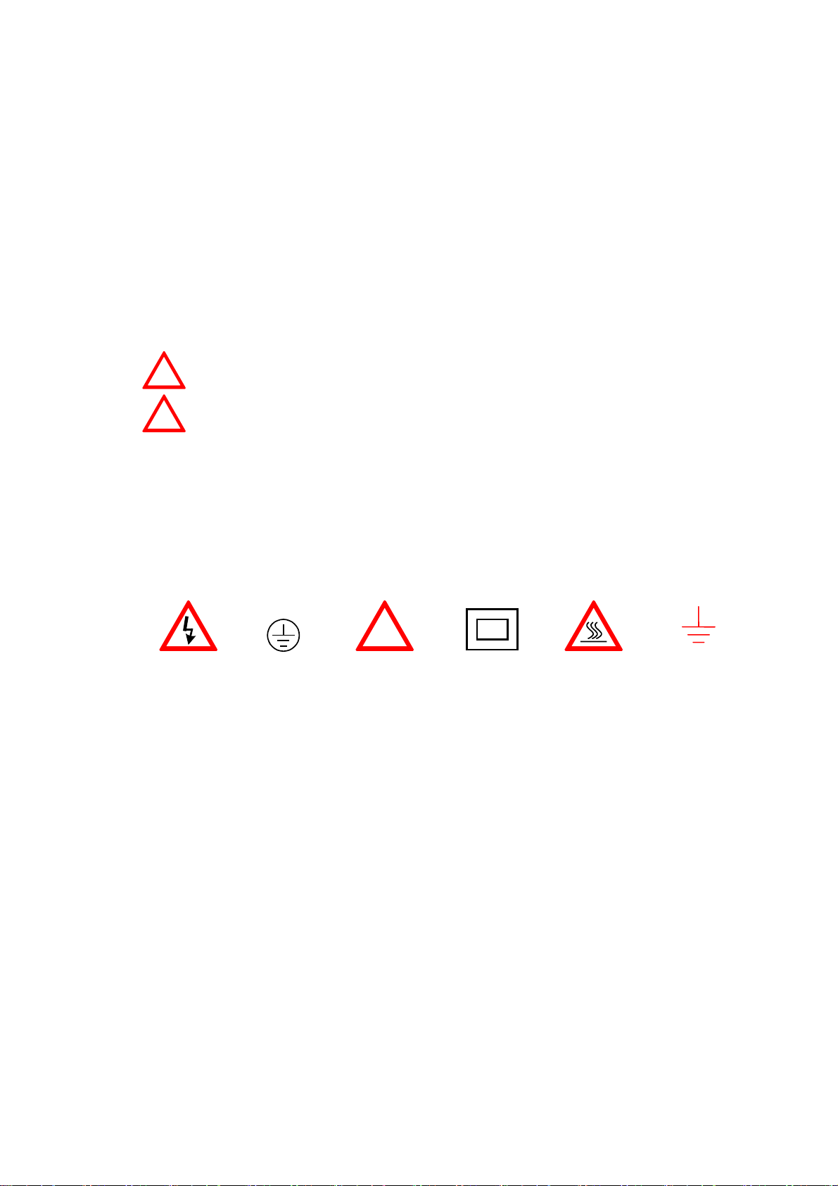
The following terms and symbols may appear on the product:
DANGER
WARNING
This term indicates an immediately accessible injury hazard.
This term indicates that an injury hazard may occur, but is
not immediately accessible.
CAUTION
This term indicates potential damage to this product or other
properties.
!
DANGER
High voltage
Protective
Conductor
Terminal
ATTENTION
refer to manual
Double
Insulated
DANGER
Hot surface
(2) Do not place any heavy objects on the instrument under any circumstances.
Earth
Ground
Terminal
(3) Disassembling the instrument
Due to the precision of this instrument, all the procedures of disassembling,
adjusting, and maintenance should be performed by a professional technician. If
the instrument has to be opened or adjusted under some unavoidable conditions,
and to be managed by a technician who is familiar with GFG-3015. Once there is
any abnormality, please contact our company or our distributor near you.
(4) Power Supply
AC input should be within the range of line voltage±15%, 50/60Hz. To prevent the
instrument from burning up, be sure to check the line voltage before turning on
power.
p. 2 GFG-3015
(5) Grounding
)
)
!
GFG-3015 can be operated only with an earth grounded AC power cord that
connects the case and ground well. This is to protect the user and the instrument
from the risk of shock hazard.
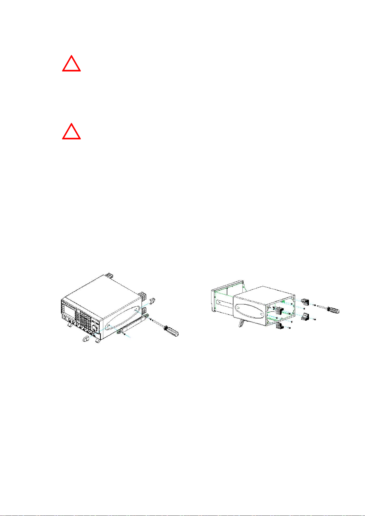
(6) Fuse Replacement
!
The fuse blows only when there is any wrong on the instrument, which will stop
working under this situation. Please find out the cause, then open the outside case
(Please see the Figure (A), Figure (B) on below) and replace a proper fuse as
listed below. Be sure to use the correct fuse before changing the applying location.
Check the line voltage setting on the rear panel. If the line voltage setting does not
match, Please change the line voltage setting according to the following steps:
1. Remove line cord from AC socket.
2. Switch the “AC line voltage switch” to correct setting with flat-blade
screwdriver and reinsert.
WARNING
WARNING
To avoid electrical shock, the power cord protective grounding
conductor must be connected to ground.
For continued fire protection, replace fuse only with the
specific type and rating by qualified personnel. Disconnect the
power cord before replacing fuse.
F101 : T 0.8A/250V
F100 : T 0.5A/250V
Figure (A
(7) Cleaning the Cabinet
Disconnect the AC power cord before cleaning the instrument.
Use a soft cloth dampened in a solution of mild detergent and water. Do not spray
cleaner directly onto the instrument, since it may leak into the cabinet and cause
damage.
Do not use chemicals containing benzing, benzne, toluene, xylene, acetone, or
similar solvents.
Figure (B
GFG-3015 p.3
(8) Operation environment
Indoor use
Altitude up to 2000m
Temperature to satisfy the specification : 18oC ~ 28oC (+64.4oF ~ +82.4oF)
Operating temperature : 0oC ~ 40oC (+32oF ~ +104oF)
Storage temperature : -10oC ~ 70oC (+14oF ~ 158oF)
Relative humidity : up to 90% when 0oC~35oC;
up to 70% when 35oC~40oC
Installation category: CAT Ⅱ(The detail is as Table A)
Pollution degree: 2
Table A
CAT Ⅳ For measurements performed at the source of the low-
voltage installation.
CAT Ⅲ For measurements performed in the building installation.
CAT Ⅱ
For measurements performed on circuits directly
connected to the low-voltage installation.
CAT Ⅰ
For measurements performed on circuits not directly
connected to Mains.
(9) Place GFG-3015 in a location with a suitable environment as stated above free
from dust, direct exposition of sunlight, and strong effect of magnetic fields.
(10) For United Kingdom
As the colours of the wires in mains leads may not correspond with the
coloured markings identified in your plug/appliance, proceed as follows:
NOTE
This lead/appliance must only be
wired by competent persons.
WARNING
THIS APPLIANCE MUST BE
EARTHED
IMPORTANT
The wires in this lead are
coloured in accordance with the
following codes:
Green/Yellow
Blue
Brown
:Earth
:Neutral
:Live
(Phase)
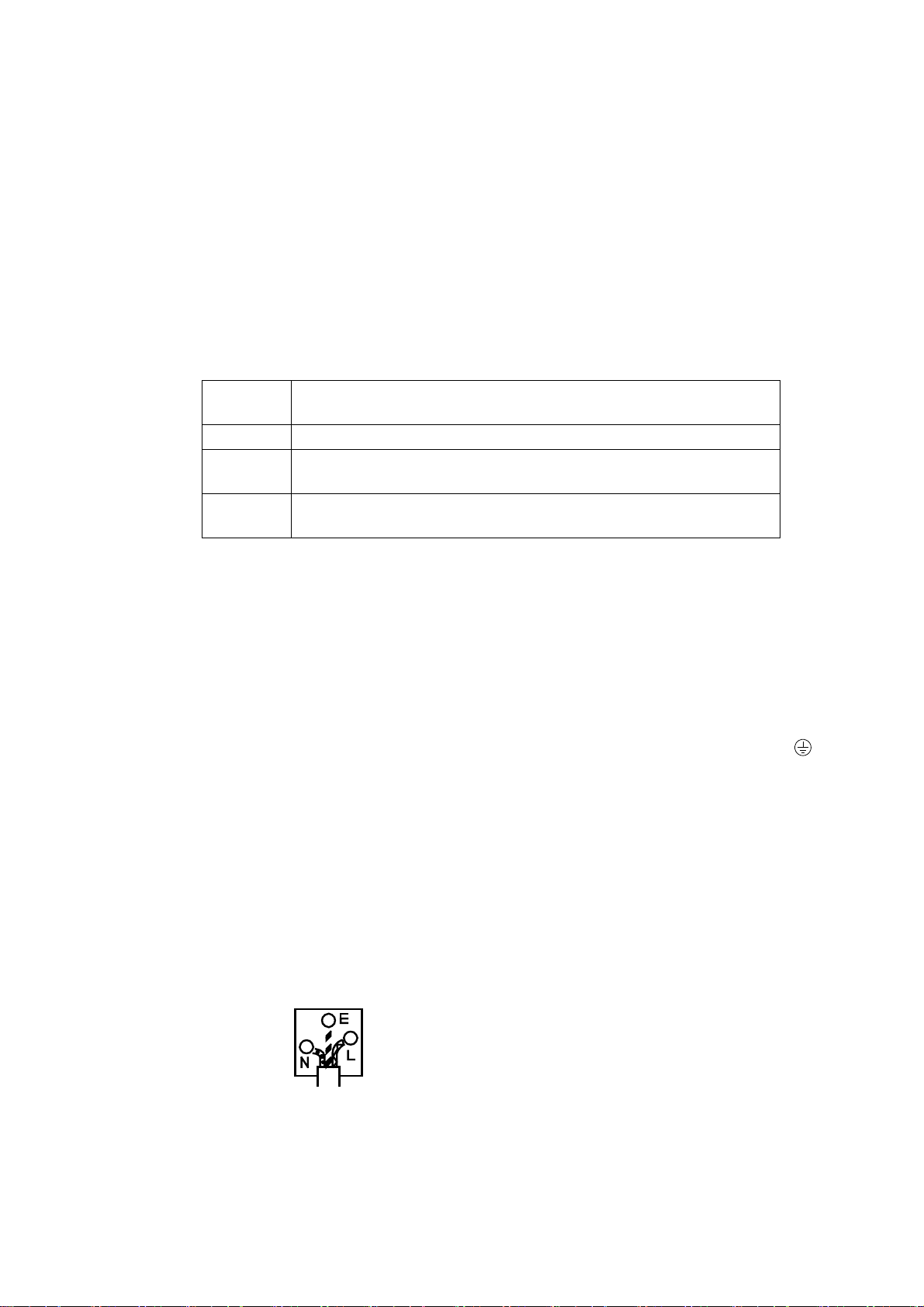
The wire which is coloured Green and Yellow must be connected to the
Earth terminal marked with the letter E or by the earth symbol
coloured Green or Green and Yellow.
The wire which is coloured Blue must be connected to the terminal which
is marked with the letter N or coloured Blue or Black.
The wire which is coloured Brown must be connected to the terminal
marked with the letter L or P or coloured Brown or Red.
If in doubt, consult the instructions provided with the equipment or contact
the supplier.
This cable/appliance should be protected by a suitably rated and
approved HBC mains fuse; refer to the rating information on the
equipment and/or user instructions for details. As a guide, cable of
0.75mm
would normally require 13A types, depending on the connection method
used.
Any moulded mains connector that requires removal/replacement must be
destroyed by removal of any fuse and fuse carrier and disposed of
immediately, as a plug with bared wires is hazardous if engaged in a live
socket. Any re-wiring must be carried out in accordance with the
information detailed in this section.
2
should be protected by a 3A or 5A fuse. Larger conductors
or
p. 4 GFG-3015
2. Product Introduction
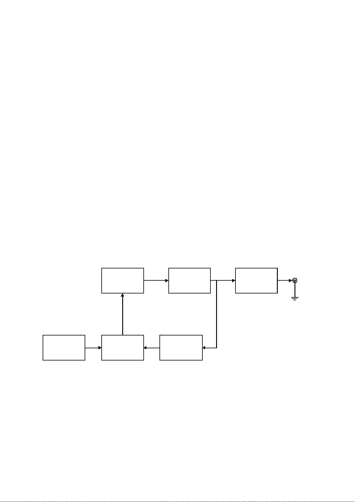
The frequency feedback method applied by GFG-3015 is a new technique that
generates stable output frequency with extraordinary accuracy for Function
Generator.
The traditional function generators typically use integrating circuit and constant
current circuit techniques that are easily affected by operation temperature or the
quality of resistor or capacitor and other key components to occur poor frequency
accuracy. The innovative design for GFG-3015 is to get rid of these problems.
The frequency feedback system needs a compatible, powerful frequency counter.
GW has designed his own full-function counter chip, GFC-9701, for this system with
high frequency test range and full functions, including Period test, Duty test, Ratio test,
Time interval, Pulse wide, direct display and direct connect with CPU system.
GFG-3015 uses this Chip to read output frequency value at any time. Then CPU
will modify the correct value of D/A converter immediately according to this value, so
that the user can get a high accuracy frequency from GFG-3015 Function Generator.
Besides, the GFG-3015 can also generate a high accuracy frequency to provide
high frequency resolution.
Graph1 indicates the fundamental construction of a frequency feedback system.
D/A
Convertor
User
Interfac e
Except the different design from the typical circuit, GFG-3015 system also has
micro controller (CPU unit) equipping an additional RS-232 interface functions which
will be used on any test system with other instrument or to be controlled by computer.
CPU
(GFC-9701)
VCO
Counter
AMP O/P
GFG-3015 p.5

3. Features
GFG-3015 is a functional Function generator that applies Frequency feedback
control system technique and can generate high frequency accuracy with high
resolution. Its main signal source can generate waveforms including sine wave,
square wave, triangle wave, and ramp wave.
There are additional features listed as follows:
All digitized operation user interface
Output Waveforms of Sine, Square, Triangle, Ramp, Pulse, AM, FM, Sweep,
Trigger and Gate or Burst.
Wide output frequency range 0.01Hz ~ 15MHz.
High frequency accuracy 0.02% ± 5 count.
Maximum frequency resolution 10mHz.
Dual displays indicate frequency and amplitude or other necessary information.
Built-in 6-digit INT/EXT Function Counter and up to 150MHz frequency range with
high resolution.
INT/EXT AM/FM Modulation with internal modulation signal output.
LIN/LOG Sweep Mode with internal sweep signal output.
VCF of 100:1 EXT Frequency Control.
SYNC Output.
TTL Output.
Synchronization GCV Output.
Variable DC Offset Control
Output Overload Protection
RS232 Interface Standard
p. 6 GFG-3015
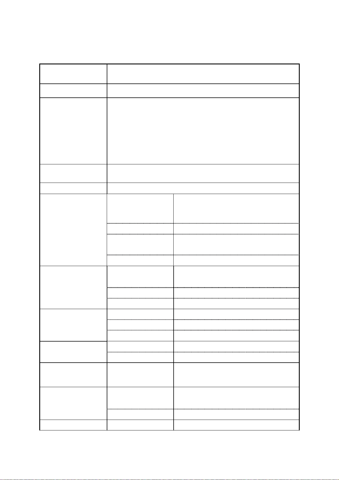
4. Specifications
Output Waveforms
Frequency Range
Frequency
Resolution
Frequency
Accuracy
Output Impedance
Amplitude
Sine, Square, Triangle, ± Ramp, Pulse, AM, FM, Sweep,
Trigger, Gate or Burst
10mHz~15MHz in 8 Frequency Range (auto switch)
1.5001MHz ~ 15.0000MHz …(100Hz)
150.01kHz ~ 1.50000MHz…(10Hz)
15.001kHz ~ 150.000kHz…(1Hz)
1.5001kHz ~ 15.0000kHz…(0.1Hz);
150.01Hz ~ 1.50000kHz…(10mHz)
15.01Hz ~ 150.00Hz…(10mHz)
1.51Hz ~ 15.00Hz…(10mHz)
0.01Hz ~ 1.50Hz…(10mHz)
0.02% ±5 Count
50Ω ± 10%
10.00V~0.01V (into 50Ω) 4 amplitude
Range
Resolution 10mV(10.00V~0.01V)
ranges
| Vac peak | + | Vdc | < 5V
DC Offset
Duty
Sync Output
Sine
Square
Accuracy
Unit Vpp, Vrms, dBm
Range
Resolution 10mV
Accuracy ≤3% ±3count at Amplitude Min.
Control Range
Resolution 1%
Accuracy
Impedance 50 Ω ±10%
Level >1Vp-p open circuit
Distortion
Asymmetry
≤3% ±5count at 10Hz~1MHz
≤10% ±5count at 1MHz~15MHz
± 5V (into 50Ω)
| Vac peak | + | Vdc | < 5V
80%:20%:80% to 1MHz
≤1% to 1MHz at 50% Duty
≤0.5%(-46dBc) From 10Hz~100kHz
≤-30dBc To 15MHz
(Spec. applied form 1Vpp to 10Vpp)
±1% of period + 3ns
Triangle and Ramp
Rise or Fall Time <18nSec
Linearity Error <1% of full scale output at 100Hz
GFG-3015 p.7
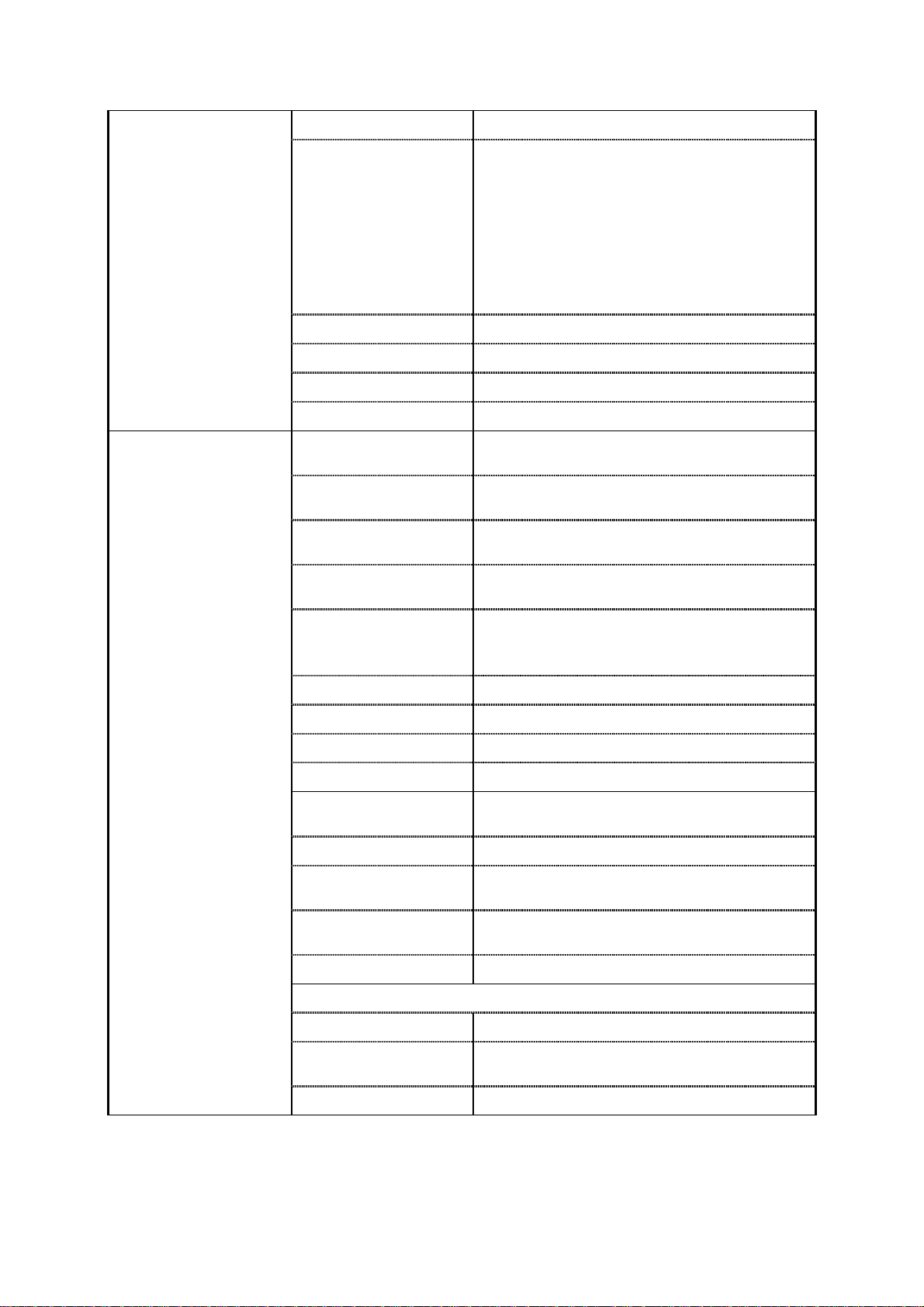
Sweep
Sweep Mode Linear or Log sweep
150kHz~15MHz
15kHz~1.5MHz
1.5kHz~150kHz
Sweep Range
150Hz~15kHz
15Hz~1.5kHz
1.5Hz~150Hz
0.15Hz~15Hz
0.01Hz~1.5Hz
Width >100:1(In Same Frequency Range)
Rate 0.01Hz~10kHz
Symmetry Control 90:10:90 ; Resolution:1%
Sweep output 0 to≥-5Vp-p into 10k Ω
Types
Waveform
Rate Frequency
Range
Rate Frequency
Accuracy
Rate Frequency
Resolution
AM, FM, Sweep, Trigger(int/ext), Gate or
Burst (Implement by Trigger Type)
Sine, Square, Triangle, Ramp or Variable
Symmetry Pulse
10mHz~10KHz in 3 Frequency Range
(auto switch)
5%±1 count
10.0kHz~0.1kHz(100Hz)
99Hz~1Hz(1Hz)
0.99Hz~0.01Hz(0.01Hz)
Symmetry 90%:10%:90%; Resolution:1%
Modulation
Symmetry Accuracy
Output Level
±1 count(≤1%)
≧1Vpp into 10kΩ load
Sine Wave Distortion ≤2% from 10Hz to 10kHz
Amplitude
Modulation
Depth 0~100%
Modulation
Frequency Rate
Carries -3dB
Bandwidth
0.01Hz ~ 10kHz(INT) DC~1MHz(EXT)
<100Hz to >5MHz
External Sensitivity ≤10Vpp for 100% modulation
Frequency Modulation
Deviation 0~±15%
Modulation
Frequency Rate
0.01Hz ~ 10kHz(INT) DC ~ 50kHz(EXT)
External Sensitivity ≤5Vpp for 15% deviation
p. 8 GFG-3015
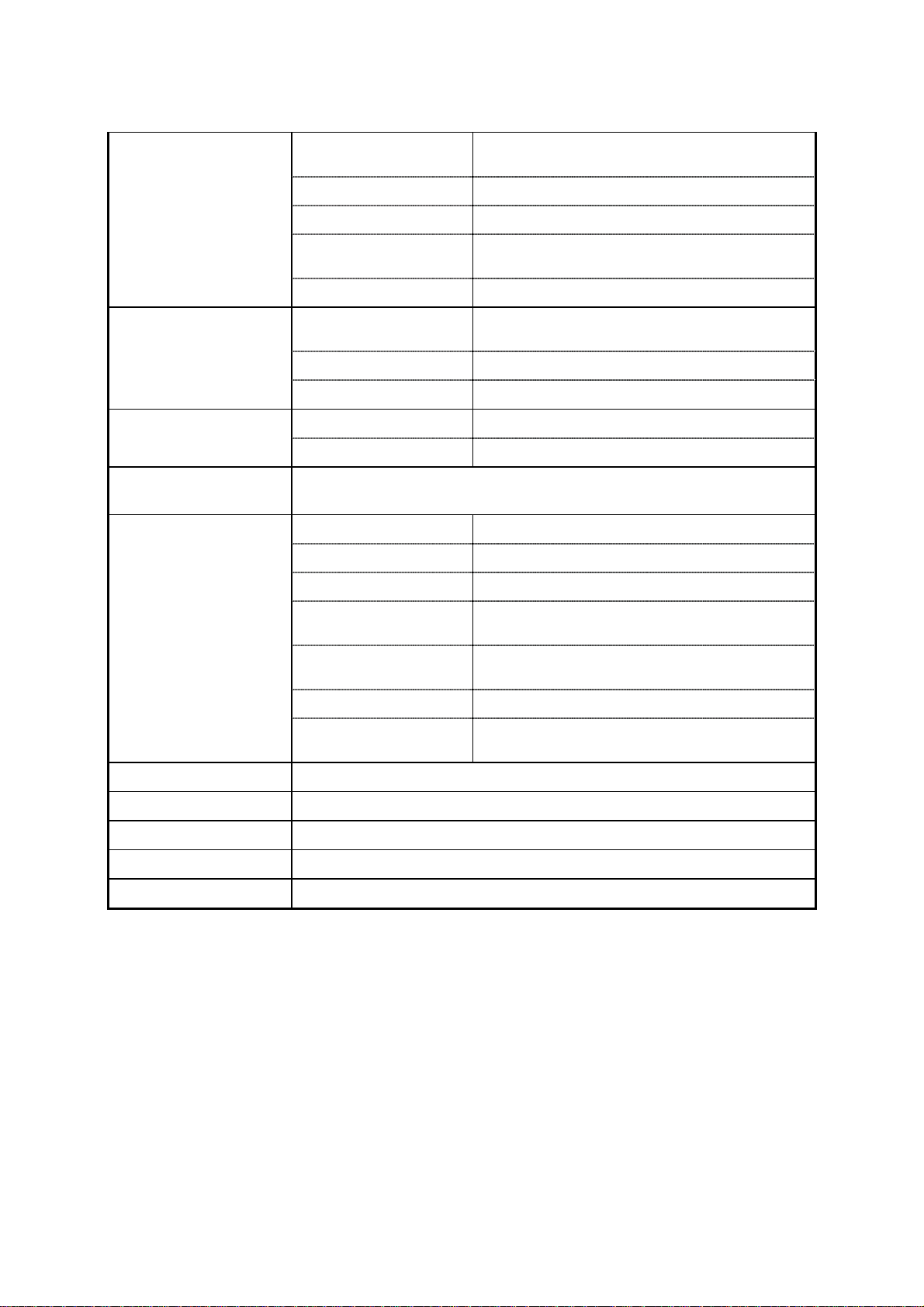
Start/Stop Phase
Range
Rate 0.01Hz~10kHz
-90º ~ +80º
Trigger
VCF
TTL Output
GCV Output
Frequency Counter
Interface
Frequency Range 0.1Hz ~ 1MHz(Useful to 10MHz)
Ext Trig Frequency
Range
DC to 1MHz,TTL compatible input level
Gate or Burst Implement by Trigger setting.
Range
100:1(0 to 10V± 1V) In Same Frequency
Range
Input Linearity <0.5% to 1MHz,<5% to 10MHz
Input Impedance 10 k Ω
Level
≧3Vpp
Fan-out >10 TTL Load
To set the voltage between 0.2V to 2V as per different
Frequency in Same frequency Range
INT/EXT Switch Selector
Range 5Hz~150MHz EXT
Accuracy Time Base(10MHz) Accuracy ± 1 count
Time Base
Resolution
± 20ppm(23ºC ± 5ºC) after 30 minutes
warm up
The maximum resolution is 100nHz for
1Hz and 1Hz for 100MHz
Input Impedance 1MΩ // 150pF
Sensitivity
≤35mVrms(5Hz~100MHz);
≤45mVrms(100MHz~150MHz)
RS232
Accessories
Power Source
Dimensions
Weight
GTL-101 × 2, Instruction Manual × 1, Power cord × 1
115/ 230V AC ±15%, 50/60Hz
290 (W) × 142 (H) × 346 (D) mm
Approx. 5kg
GFG-3015 p.9
5. Front and Rear Panels
Front Panel
p. 10 GFG-3015

1
Q
POWER button
:
Push the button to turn on the power, and the display is
activated. Push again the button to turn off the power.
2
Main Function keys
FUNC
:
Key is to set main output waveform in the cycle of
Sine, Triangle and Square. When the key is pressed, the
related waveform LEDs will light up accordingly.
FRE
Key is to set main frequency entry mode. Key in the
desired value of frequency by using the number keys or
Modify keys and Unit keys.
When the key is pressed, the FREQ
LED (on parameter
display area A) will be flashing until other mode is set.
AMPL
Key is to set main amplitude entry mode. Key in the
desired value of voltage by using the number keys or Modify
keys and Unit keys.
When the key is pressed, the AMPL
LED (on parameter
display area B) will be flashing until other mode is set.
OFFSET
Key is to set main output offset voltage entry mode.
Key in the desired value of voltage by using the number keys
or Modify keys and Unit keys.
When the key is pressed, the OFFS
LED (on parameter
display area B) will be flashing until other mode is set.
DUTY
Key is to set main output Duty Cycle entry mode. Key
in the desired value of percentage by using the number keys
or Modify keys and Unit keys.
When the key is pressed, the DUTY
LED (on parameter
display area B) will be flashing until other mode is set.
3
Modulation/Sweep
Function keys
MOD/ON
Key is to start performing Amplitude Modulation,
Frequency Modulation or Sweep function. When the key is
pressed again, the functions will stop.
When the key is pressed, the ON/OFF
LED (on MOD/SWP
Function LED area) will light up, press again the key, the LED
will be off.
:
These keys control the functions of sweep and modulation.
SOURCE
SPAN
Key is to set Span of Modulation or Sweep entry
mode and choose the source of modulation.
If set to source choose function, must use Secondary
Function mode.
FM
AM
Key is to choose the type of modulation between AM
and FM. If want to set to FM function, must use Secondary
Function mode.
INT/EXT
RATE
Key is to set Rate of Modulation, Sweep or Trigger
entry mode and choose the signal source of Modulation,
Sweep or Trigger.
If want to set to signal, must use Secondary Functions mode.
GFG-3015 p.11
R
pp
4
System keys
STOP
START
Key is to set Start Frequency of Sweep entry mode
and Stop Frequency of Sweep entry mode.
If set to Stop Frequency of Sweep entry mode, must use
Secondary Functions mode.
LOG S
LIN S
Key is to choose the type of Sweep between liner
sweep and LOG sweep.
If set to LOG sweep, must use Secondary Function mode.
SWP CF
SYM
Key is to set the Duty cycle of Modulation, Sweep or
Trigger source entry mode. Key in the desired value of
percentage by using number keys or modify keys and Unit
keys. If want to set to center frequency of Sweep function that
must use Secondary Functions mode.
When the key is pressed, the SYM
LED (on parameter
display area B) will be flashing until other mode is set.
When you use center frequency entry mode then the CF
(In parameter display area A) will be flashing until other mode
is set.
The detail operation of these keys. Please refer to the
instruction in next Chapter.
RECL
:
Key is to save or reload the setup parameters of the
STO
instrument into or take out from memory; the selected
DEFAU
numbers is from 0 to 9, up to 10 groups.
DEFAU
RS232
RS232
Key is to start performing RS232 interface. Press the
key then use rotational knob to change function states (ON or
OFF).
Press the key again then use rotational knob to change the
Baud rate. The cycle order is in 300, 600, 1200, 2400, 4800,
9600 and 19200 sequence.
If set the instrument to default state, must use Secondary
Function mode.
LED
SHIFT
Key is to set the Secondary Functions mode. When
the key is pressed, the instrument will choose Secondary
Function and the SHIFT
For example, press + can recall the default
LED will light up.
SHIFT
value of the instrument.
5
Unit keys
DEG/%
:
In ‘Normal’ mode, these
MHz/dB
KHz/Vrms Hz/V
keys are used to assign the unit and to set the entered value.
For example, you can use dBm and Vpp to set the output
amplitude. They can be used to set frequency (MHz, kHz, Hz),
OFFSET, and PHASE, etc.
In STOR or RECL modes, they are used as ‘Enter’.
p. 12 GFG-3015
6
Entry keys
7
Modify keys
:
To and keys are used to input
9 .0
value. A unit key should be pressed to set the entered value.
-/BK SP
key is blank space that used to delete the entered
value entirely and the other function is minus key .
:
◄
Keys are used to change the digit of input
►
value.
User can use the Rotate knob for increasing or decreasing that
digit.
HOLD
Key to terminate the function of all Modify keys until
user press this key again.
When the key is pressed, the HOLD
LED will light up until the
key is pressed again.
8
Trigger Function keys
9
Counter Function key
10
Parameter display
Area (A)
TRIG ON
:
Key is to start performing Trigger function mode. If
the key is pressed again, the function will stop.
When the key is pressed, the ON/OFF
LED (In Trigger
Function LED area) will light up until the key is pressed again
(The LED will light off).
SIGL/MUT
Key is to choose the type of Trigger, Single-trigger or
multi-trigger.
When the key is pressed, the MULT
or SINGL LED (In
Trigger Function LED area) will light up accordingly.
PHASE
Key is to set the phase of trigger function entry
mode. Key in the desired value of percentage by using
number keys, modify keys and Unit keys.
When the key is pressed, the PHASE
LED (In parameter
display area B) will be flashing until other mode is set.
TRIG EXT
Key is to choose the Trigger signal source, internal or
external.
When the key is pressed, the EXT
LED (In Trigger Function
LED area) will light up accordingly until the key is pressed
again (The LED will light off).
INT/EXT
:
Key is to set the Gate time of External counter
GATE
function. The cycle order is according to 0.01s, 0.1s, 1s, and
10s. When the key is pressed, the Gate time LEDs will light up
according user’s wish.
The other function is to choose input signal source of counter,
internal or external, by using Secondary Function mode.
:
The 6-digit Parameter display presents the parameter values
and information about the current status and unit.
The START
LED light on indicated that the value of display
was Start frequency of sweep function right now.
The STOP
LED light on indicated that the value of display was
Stop frequency of sweep function right now.
The CF
LED light on indicated that the value of display was
center frequency of sweep function right now.
GFG-3015 p.13
11
Parameter display
Area (B)
12
Waveform Function
LEDs
13
Counter Functions
LEDs
14
Modulation/Sweep
Function LEDs
The FREQ LED light on indicated that the value of display was
main output frequency right now.
The RATE
LED light on indicated that the value of display was
rate frequency of sweep or modulation or trigger function right
now.
The SPAN
LED light on indicated that the value of display was
Span frequency of sweep function right now.
The MHz
, kHz, Hz and mHz LED light on indicated that unit
according current value of display.
:
This 4-digit Parameter display presents the parameter values
and information about the current status and unit.
The AMPL
LED light on indicated that the value of display was
main output amplitude right now.
The OFFS
LED light on indicated that the value of display was
main output DC offset voltage right now.
The DUTY
LED light on indicated that the value of display was
main output duty cycle right now.
The SPAN
LED light on indicated that the value of display was
span frequency of modulation function right now.
The SYM
LED light on indicated that the value of display was
modulation signal duty cycle of sweep or modulation or trigger
function right now.
The PHASE
LED light on indicated that the value of display
was phase of trigger function right now.
The STOR
LED light on indicated that the value of display was
save group number right now.
The RECL
LED light on indicated that the value of display was
reload group number right now.
The V
, rms, dBm kHz, Hz, % and DEG LED light on indicated
that unit according current value of display.
:
These LEDs indicate the figure of main output waveform and
the current operation functions.
:
These LEDs indicate the GATE TIME of external counter and
the current value.
:
These LEDs indicate the current status of Sweep and
Modulation and the current operation functions.
The AM
LED lights on to indicate the setting status of
amplitude modulation function.
The FM
LED lights on to indicate the setting status of
frequency modulation function.
The LIN
LED lights on to indicate the setting status of liner
sweep function.
The LOG
LED lights on to indicate the setting status of LOG
sweep function.
The Sine
, Triangle and Square LED light on indicated that
according Modulation source waveform.
The EXT
LED lights on to indicate the external sweep or
modulation signal source.
The ON/OFF
LED lights on to indicate that the sweep or
modulation function is enabled.
p. 14 GFG-3015

15
Trigger Function LEDs
16
Shift mode LED
17
Hold mode LED
18
RS-232 Interface LED
19
Main Output BNC
20
Sync Output BNC
21
TTL Output BNC
22
GCV Output BNC
23
Modulation/Sweep
Output BNC
24
EXT Modulation/Trigger
Input BNC
25
VCF Input BNC
26
EXT Counter Input BNC
:
These LEDs indicate the current status of trigger function on
display and the current operation functions.
The MULT
LED lights on to indicate the trigger setting status
of multi-trigger type.
The SINGL
LED lights on to indicate the trigger setting status
of Single-trigger type.
The EXT
LED lights on to indicate the external trigger signal
source.
The ON/OFF
LED lights on to indicate that the trigger function
is enabled.
The SHIFT LED light on indicated that the enter mode is
:
Secondary Functions right now.
The HOLD LED lights on to indicate that all modify keys is
:
disabled.
The RS232 LED indicates the current operation status with the
:
RS-232 interface bus.
:
This is the BNC connector that outputs all main signals. Output
resistance is 50Ω.
:
This is the BNC connector that outputs sync signals. Output
resistance is 50Ω.
:
This is the BNC connector that outputs TTL level signals.
This is the BNC connector that outputs the voltage between
:
0.2V and 2V varied with different Frequency
:
This is the BNC connector that outputs internal Sweep or
modulation signals. Output
:
This is the BNC connector for EXT amplitude/frequency
modulation or EXT sweep signal input.
The amplitude modulation index is 100% when ≤10Vpp is
input.
The frequency modulation index is 15% when ≤5Vpp is input.
The trigger mode input signal is compatible with TTL level.
:
This is the BNC connector for VCF signal input.
The frequency variation width index is 100:1 when
input. Input
:
This is the BNC connector for external counter signal input.
The Input
Impedance is 10kΩ.
Impedance is 1MΩ // 150pF
Impedance is 10kΩ.
10V± 1V is
GFG-3015 p.15
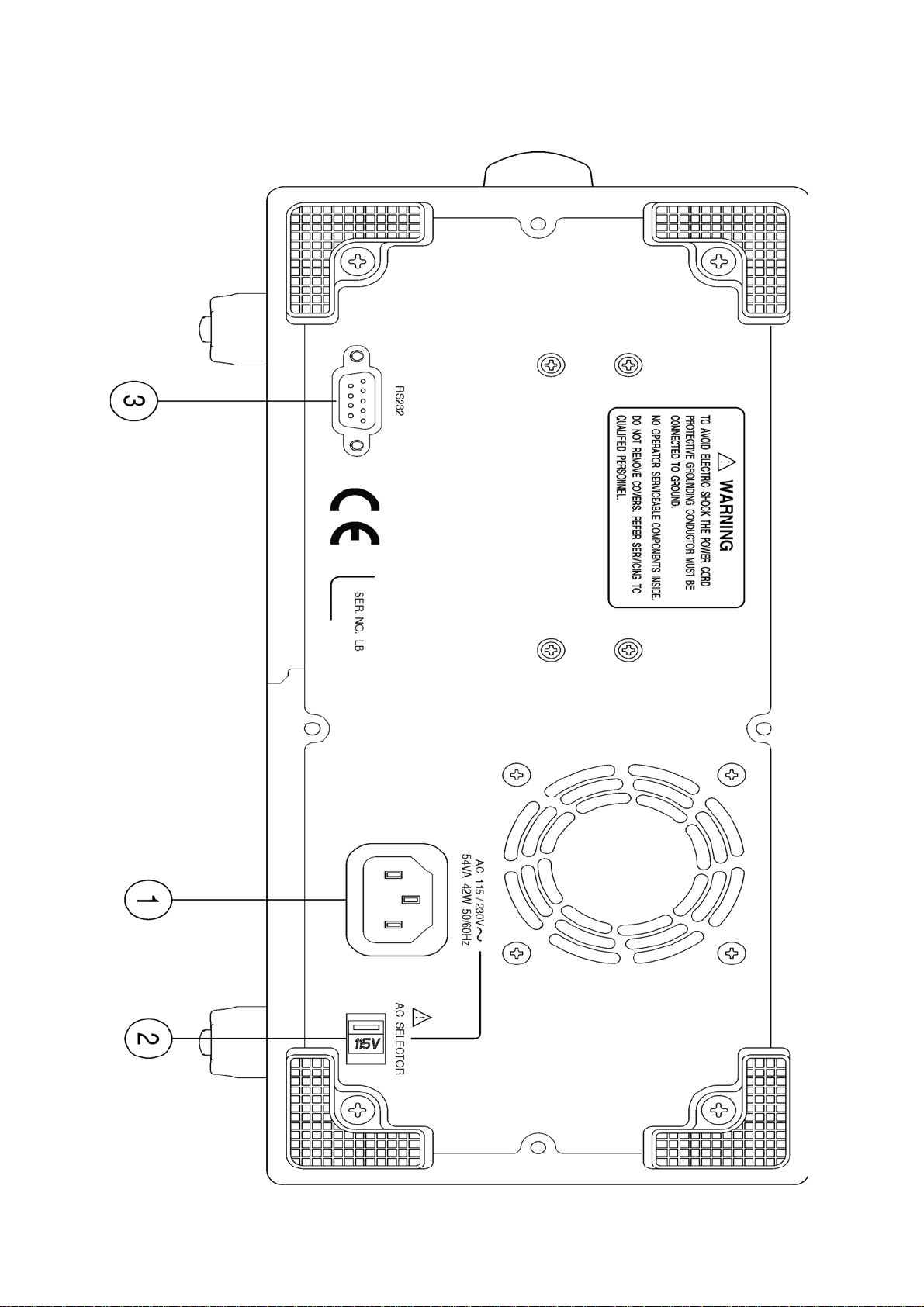
Rear Panel
p. 16 GFG-3015

1
Power Entry model
2
Line Voltage Selector
3
RS232 connector
:
This is the AC power input terminal. AC input should be within
the range of line voltage±15%, 50/60Hz.
:
This switch can choose the current line voltage between 115V
and 230V
:
This is the port of serial RS232 interface. The DCE and Baud
rate is among 300 ~ 19.2k.
GFG-3015 p.17
pp
6. Operation
Q
Q
6.1 The First Step Setup For Instrument
n Ensure that the voltage of main supply is compatible with this instrument. The
selector on the rear panel states the required AC line voltage.
o Connect the instrument to main supply with the power cord.
p Press the Power Switch, all control functions will be shown on the parameter
display area.
DEFAU
q Press + can recall the default value of this instrument.
SHIFT
RS232
6.2 The Setup of Output Function
n Press key to select main output waveform. The Waveform will change
when you press this key each time. The cycle order is according to Sine,
Triangle, Square.
When the key is pressed, the waveform LEDs will light up according to the
mentioned cycle order of output waveform.
o Set different duty cycle ratio (not 50%) for Triangle or Square waveform to get
±Ramp or different Pulse width square waveform.
FUNC
6.3 The Setup of Frequency
n Set to Frequency Entry mode by pressing button, the FREQ LED (In
parameter display area A) will be flashing.
o Key in the desired value of frequency.
p Select a proper unit-button to specify the value.
q In addition, you can use and the Rotate Knob to adjust the
◄ ►
main frequency value you need.
FRE
Note: The frequency range of this instrument is from 10mHz to 15MHz in 8 Frequency
Range. The details and resolution is as below. But those ranges will auto switch
according to the enter value.
Frequency Range
10mHz~15MHz in 8 Frequency Range (auto switch)
1.5001MHz ~ 15.0000MHz …(100Hz)
150.01kHz ~ 1.50000MHz…(10Hz)
15.001kHz ~ 150.000kHz…(1Hz)
Frequency
Resolution
1.5001kHz ~ 15.0000kHz…(0.1Hz);
150.01Hz ~ 1.50000kHz…(10mHz)
15.01Hz ~ 150.00Hz…(10mHz)
1.51Hz ~ 15.00Hz…(10mHz)
0.01Hz ~ 1.50Hz…(10mHz)
Example of the Setup Frequency
1. To set frequency at 250Hz
Press first, then key in and press .
p. 18 GFG-3015
FRE
2 5 0
Hz/V
pp
pp
2. To modify the frequency to 850Hz.
Press or to move flash digit to “ 2 ” position.
◄ ►
Then turn the Rotate Knob clockwise until the digit become to “ 8 ”.
6.4 The Setup of Amplitude
n Set to Main Amplitude entry mode by pressing button to, now the AMPL
LED (In parameter display area B) will be flashing.
o Key in the desired value of Amplitude.
p Select a proper unit-button to specify the value.
AMPL
q In addition, you can use or and the Rotate Knob to modify the
◄
►
main Amplitude value you need.
Example of the Setup Amplitude
1. To set Amplitude at 8 Vpp.
Press first, then key in and press .
AMPL 8
Hz/V
2. To modify the Amplitude to 5 Vpp.
Press or to move flash digit to “ 8 ” position.
◄ ►
Then turn the Rotate Knob anti-clockwise until the digit become to “ 5 ”.
The input limit : (1) Amplitude should be among 0.01 ~ 10Vpp.
(2) Offset should be among ±5Vpp.
(3) AMPL + |2 × OFFSET| ≤ 10Vpp.
6.5 The Setup of Offset
n Set to main DC offset Voltage entry mode by pressing button, now the
OFFS LED (In parameter display area B) will be flashing.
o Key in the desired value of DC offset voltage.
p Select a proper unit-button to specify the value.
OFFSET
q In addition, you can use and the Rotate Knob to modify the
◄
►
main DC offset voltage value you need.
Example of the Setup Offset
1. To set DC offset voltage at 1 Vpp.
Press first, then key in and press .
OFFSET 1
Hz/V
2. To modify offset voltage to 2 Vpp.
Press or to move flash digit to “ 1 ” position.
◄
►
Then turn the Rotate Knob clockwise until the digit become to “ 2 ”.
The input limit : (1) Amplitude should be among 0.01 ~ 10Vpp.
(2) Offset should be among ±5Vpp.
(3) AMPL + |2 × OFFSET| ≤ 10Vpp.
GFG-3015 p.19
 Loading...