

Page 1
User Manual
Smart Energy Controller
SEC1000S
V1.1-2023-05-30
Page 2

1 Symbols
01
2 Safety and Warning
3 Mounting
3.2 Overview and Packaging
3.3 Inverter Installation
4 Troubleshooting
5 Technology parameter
6 Relevant Certication
01
023.1 Mounting Instruction
02
03
10
10
10
Page 3
1 Symbols
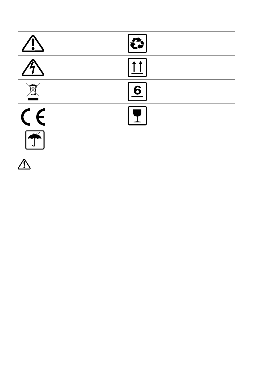
Caution! - Failure to observe a warning
indicated in this manual may result in
minor or moderate injury.
Danger of high voltage and electric
shock!
Product should not be disposed as
normal house hold waste.
CE Mark
Keep Dry – The package/product must be protected
from excessive humidity and must accordingly be
stored under cover.
Components of the product can be
recycled.
This side up - The package must always be
transported, handled and stored in such a way
that the arrows always point upwards.
No more than six (6) identical
packages be stacked on each other.
The package/product should be
handled carefully and never be
tipped over or slung.
2 Safety and Warning
SEC1000S of GoodWe Technologies Co., Ltd. (hereinafter referred to as GoodWe) has been designed
and tested strictly according to the international safety regulation. As electrical and electric
equipment, Safety Regulation shall be followed during installation and maintenance.Improper
operation may bring severe damage to the operator,the third party and other properties.
• Installation.maintenance of SEC1000S must be performed by qualied personnel.in compliance
with local electrical standards. regulations and the requirements of local power authorities.
• To avoid electric shock,make sure the connection between SEC1000S and AC output of inverter.
SEC1000S and Grid, is disconnected before performing any installation or maintenance.
• When in operation,users should not touch any of the electrical parts of SEC1000S ,like internal
components.cables, to avoid electic shock.
• All electrical installations must comply with local electrical standards and obtain permission from
local power authorities before SEC1000S can be connected to the grid by professionals.
• Before replacing any internal components of SEC1000S, the connection between the inverter
and SEC1000S,the power grid and SEC1000S must be disconnected, and the newly replaced
components must meet the requirements of SEC1000S. Otherwise, GoodWe will not assume the
responsibility and quality assurance for the personal harm.
• Make sure that the AC input voltage and input current match the rated voltage and current of
SEC1000S, otherwise the components will be damaged or cannot work properly,and GoodWe will
not assume the responsibility and quality assurance for this case.
• There are lightning protection modules inside.Make sure to connect the internal PE with the
ground when intalling SEC1000S.
• When in operation, do not plug or unplug cables of SEC1000S.
• SEC1000S must be Installed out of reach of children.
• Appropriate antistatic measures should be taken.
• SEC1000S supports the three-phase four-wire grid structure only.
• Can only be used in spontaneous self-use mode.
01
Page 4
3 Mounting
3.1 Mounting Instruction
• SEC1000S must be installed where there is no signicant shaking, shock vibration and no direct
rain or snow.
• SEC1000S shall be installed at eye level for easy operation and maintenance.
• SEC1000S shoud not be installed near inammable and explosive items.Any strong electromagnetic equipment should be kept away from installation site.
• SEC1000S shall be installed at a location free from explosive hazardous media and free from gas
and dust sucient to corrode metals and destroy insulation.
• SEC1000S parameters and warning signs must be clearly visible after installation.
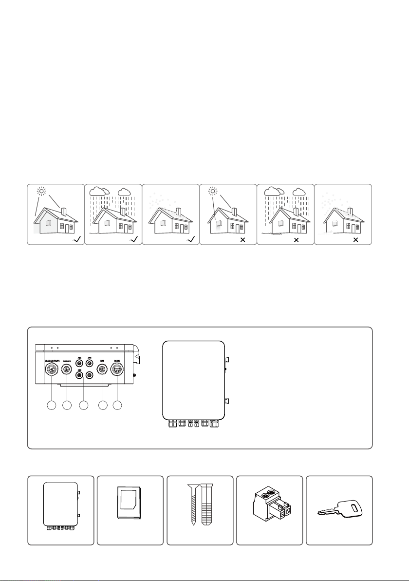
• SEC1000S should be installed without sunshine, rain and snow.
No sunlight No rain No snow Sunlight
Rain Snow
3.2 Overview and Packaging
After opening the package,conrm if it is consitent with specication of SEC1000S you purchased.
3.2.1 SEC1000S Overview
1.AC voltage input port(L1/L2/L3/N/PE)
Note: SEC1000S supports the three-phase
four-wire grid structure only, which means
the Neutral wire is necessary.
2.GPRS antenna output port ( Antenna)
3.AC voltage output port(external CT)
1 2 3 4 5
3.2.2 Package
.....
...........
...........
Figure3.2.1
.....
4.LAN network port (NET)
5.Communication port of the
inverter(RS485)
SEC1000S×1 User manual×1
Expansion screw×3
2 Pin terminal×4
Key×4
02
Page 5
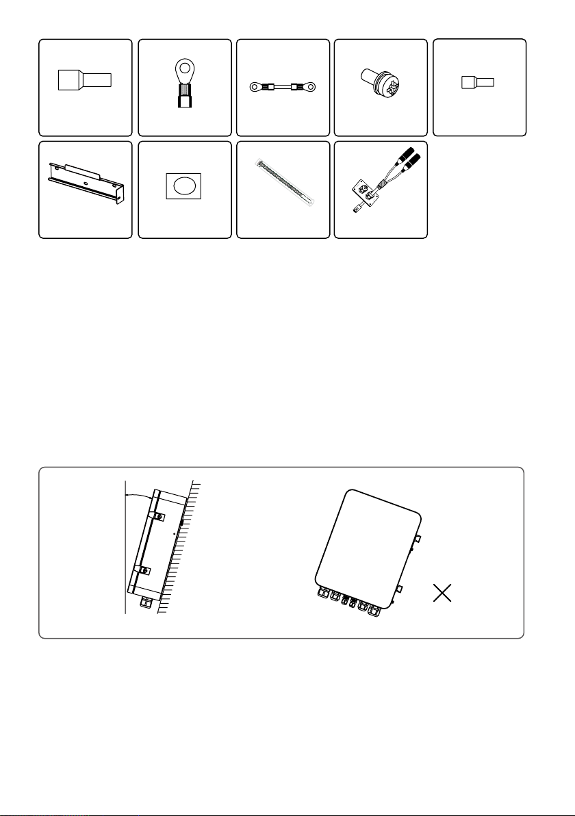
Tubular terminal×6
O type terminal×8 Short wire×3 Screw×1
Tubular terminal×8
Back hang×1
Fireproong mud×1
Ribbon×5 1 to 2 Wire Harness×5
3.3 SEC1000S Installation
3.3.1 Selecting the installation location
The following must be considered when selecting the best location for an SEC1000S.
• The mount and installation method must be appropriate for the SEC1000S’s weight and
dimensions.
• Install on a sturdy surface.
• The installation location must be well ventilated.
• SEC1000S can be placed horizontally or installed vertically.
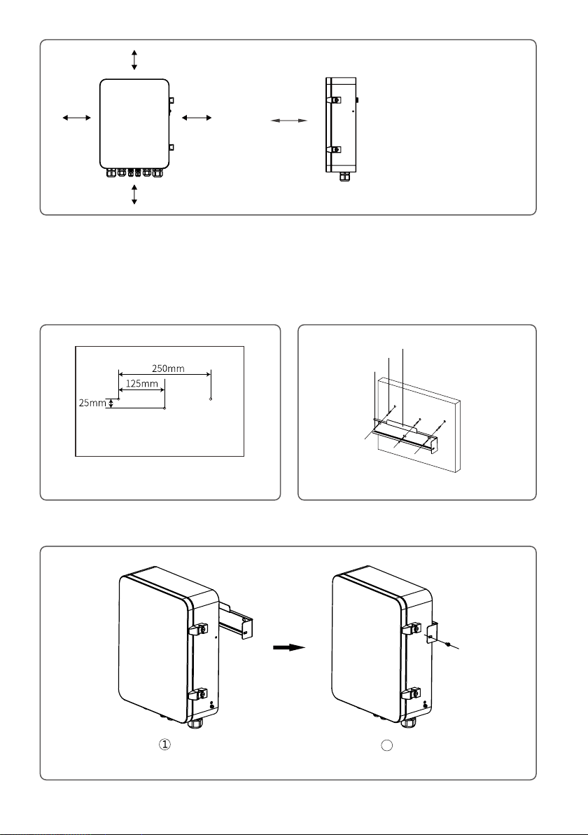
• The SEC1000S must be installed vertical or with a backward tilt less 15°.No sidwways tilt is
allowed.The connection area must point downwards.Refer to Figure 3.3.1-1.
≤15°
• To allow dissipation of heat,and for convenience of dismantling,clearances around the
SEC1000S must be no less than the values, refer to gure3.3.1-2.
03
Page 6
≥200mm
≥200mm
≥500mm
≥200mm
≥500mm
Figure3.3.1-2
Upward----------200mm
Downward-------500mm
Front--------------500mm
Both sides-------200mm
3.3.2 Mounting Procedure
(1)Drill holes on the wall,8mm in diameter and 45mm deep;Refer to Figure 3.3.2-1.
(2)Fix the wall mounting bracket on the wall with expansion bolts in accessory bag,refer to Figure 3.3.3-2.
Expansion screw tube
Back hang
Tapping screw
Hole size
Figure3.3.2-1
Figure3.3.2-2
(3)Place SEC1000S on the wall-mounted bracket as illustrated in gure 3.3.2-3.
2
Figure3.3.2-3
04
Page 7
1. SEC1000S can be placed horizontally to
work, as shown in the gure 3.3.2-4.
2. SEC1000S should be placed in a xed
place indoors as shown in the gure 3.3.2-5.
3.3.3 Port and wiring instructions
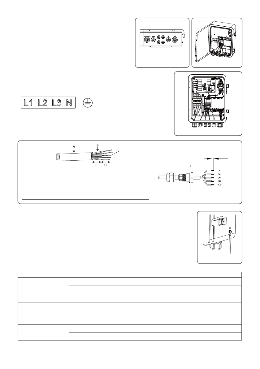
Voltage Input Port(L1\L2\L3\N\PE)
①
Input phase voltage range:AC60V-AC280V;
Input line voltage range:AC100V-AC480V;
AC Frequency:50/60Hz;
Multiple strands of soft copper wire
NO Description Content
A Wire Diameter No more than 25 mm
B Cross Sectional Area of Copper Wire R ecommend:AWG11-AWG13
C Wire Length About 45 mm
D Length of Bare Copper Wire About 12mm(10mm for PE)
Current Input Port (three sets of CT )
③
Connect three sets of external CT to the connector at the
position shown in gure 3-1(A+A-\B+B-\C+C-).
For detailed external CT connection, please refer to the CT
connection manual.
Figure3.3.2-4
Figure3.3.2-5
①②③④⑤
Use wire crimper to press
10~12mm
L1
L2
L3
(N)
PE
Recommended CT
According to the external current range, GoodWe
recommends the following specications, for reference only.
NO Range of current tested Content Remark
CT 200A Acrel/AKH-0.66(200A/5A) Backow CT,closed type(Holesize31mm*11mm, 22mm)
1 Imax<250A
2 250A≤Imax<1000A
3 1000A≤Imax<5000A
CT 250A/5A Acrel/AKH-0.66-K-30x20-250/5 Backow CT,open type(Opening size:32mm*22mm),accuracy 0.5%
CT 250A/5A Acrel/AKH-0.66-K-60x40-250/5 Backow CT,open type(Opening size:62mm*42mm),accuracy 1.0%
CT 1000A/5A Acrel/AKH-0.66-K-60x40-1000/5 Backow CT,open type(Opening size:62mm*42mm),accuracy 0.5%
CT 1000A/5A Acrel/AKH-0.66-K-80x40-1000/5 Backow CT,open type(Opening size:82mm*42mm),accuracy 0.5%
CT 1000A/5A Acrel/AKH-0.66-K-80x80-1000/5 Backow CT,open type(Opening size:82mm*82mm),accuracy 0.5%
CT 5000A/5A Acrel/AKH-0.66-K-140x60-5000/5 Backow CT,open type(Opening size:142mm*62mm),accuracy 0.2%
CT 5000A/5A Acrel/AKH-0.66-K-160x80-5000/5 Backow CT,open type(Opening size:162mm*82mm),accuracy 0.2%
05
Grounding Diagram
Page 8
Multiple strands of soft copper wire
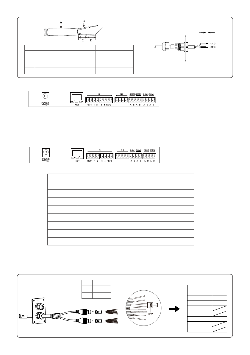
NO Description Content
A Wire Diameter No longer than 6 mm
B Cross Sectional Area of Copper Wire AWG14-AWG18
C Wire Length 45mm(more or less)
D Length of Bare Copper Wire 5mm(more or less)
LAN Network port
④
Use wire crimper to press
5mm
LAN SEC1000S uses this port when accessing a network cable;The access point is as shown in the
"NET" position in the gure above.
It is recommended to use network cables better than Super Five Type. After wiring, use the reproof mud to seal the port, to ensure its protective performance.
Communication Port
⑤
Descriptions of internal communication ports of SEC1000S are as following.
Port Description
POWER DC Power Input (Occupied)
NET Ethernet Interface
DI DRED or RCR functional interface
NC reserve
COM1 485 interface1 with Inverter
COM2 485 interface2 with Inverter
COM3 485 interface3 with Inverter
COM4 485 interface4 with SEC1000S internal Meter(Occupied)
Note:The system supports up to 10 inverters, please distribute them equally to each COM port.
When the RS485 port on the inverter is an RJ45 port, refer to the following wiring steps.
For detailed port denitions, refer to the user manual of the inverter.
RS485
Broad
PIN ASSIGNMENT
COLOR
Orange White RS485+
Orange RS485-
Green White RS485+
Blue
Blue White
Green RS485-
Brown White
Brown
NO Function
1 RS485+
2 RS485-
1
2
communication
06
Page 9
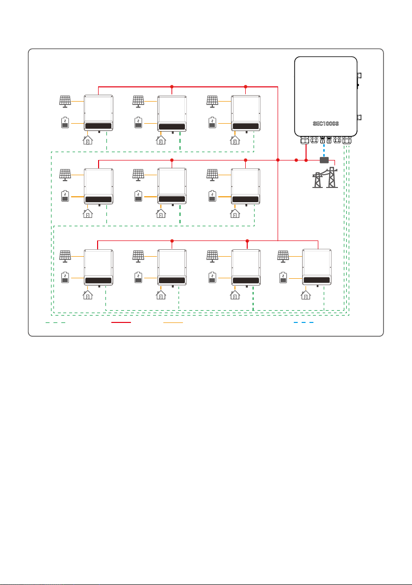
3.3.4 SEC1000S Grid Connection Diagram
PV Panels
Battery
Back-Up Loads
PV Panels
Battery
Back-Up Loads
PV Panels PV Panels PV Panels
Battery Battery Battery
Back-Up Loads
RS485 Data cable
PV Panels
Battery
Back-Up Loads
PV Panels
Battery
Back-Up Loads
Back-Up Loads Back-Up Loads
AC cable
PV Panels
Battery
Back-Up Loads
PV Panels
Utility
Battery
Back-Up Loads
PV Panels
Battery
Back-Up Loads
CT connected cableDC cable, Battery cable, AC cable (backup side)
Note:
1. The system supports up to 10 inverters, please distribute them equally to each COM port.
2. No separate Smart Meter is required in inverter paralleling system along with SEC1000S deployed. This solution
is only applicable to the paralleling of on-grid side not to back-up side. There are special requirements on the
version of rmware of ET, ET PLUS+ or BT applied in this solution, with DSP version 01 or newer and ARM version
09 or newer. The rmware version of SEC1000S designated for inverter paralleling application should be 01 or
newer.
07
Page 10
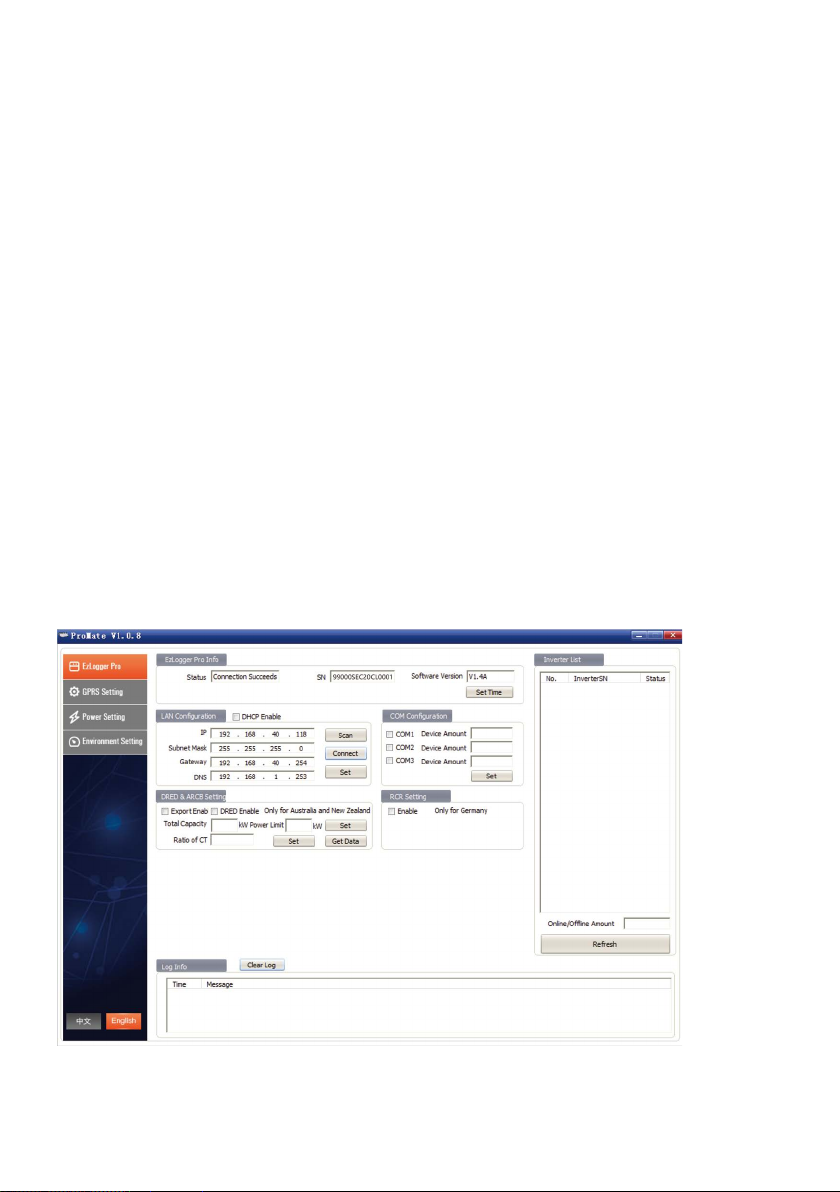
3.3.5 Main functions of SEC1000S
In the Grid Connection Diagram as shown in 3.3.4( quantity of Inverter can be more than one),
SEC1000S will have the functions of Active Power Regulation, and Back ow prevention, etc. The
corresponding parameters of the inverter are acquired and set through the software ProMate
installed in computer for monitoring and conguring SEC1000S. ProMate is a kind of software that
can congure Ezlogger Pro, SEC1000S etc. It can modify the network IP address of Ezlogger Pro
and SEC1000S, congure the number of connected inverters, time setting, RCR, DRED function,
conguration and on-site debugging. First, the user need to install "ProMate" in the computer by
downloading ProMate from Internet (https://en.goodwe.com/), Please access to the website to
download the program and competethe installation. If the user needs to use ProMate software to
congure SEC1000S, it needs to be set in dynamic IP(DHCP) or static IP according to the network
connection mode.
(1)If the user is in the dynamic IP mode, he/she only needs to connect the SEC1000S NET port to the
Router LAN port with the network cable to connect to the network, namely plug and play.
(2)If the user has a static IP, it is necessary to switch SEC1000S to the static IP mode. That is, press
the Reload key for about 10 seconds to reset and restart SEC1000S, About 10 seconds after pressing
the Reload button, the LED lights on the SEC1000S internal EzLogger Pro Panel will blink from right
to left and reset and restart.
After restart, SEC1000S will be switched to static IP mode(default IP:192.168.1.200), then use cables
to connect SEC1000S“NET” port to the Ethernet port of the computer.At the same time, the IP
address of the computer needs to be modied. The IP address and the default gateway should be
set at 192.168.1.xxx segment (1 ≤XXX ≤250 and XXX ≠200). For example, the IP address can be set
as 192.168.1.100 and the default gateway as 192.168.1.254.
The interface of Promate is as follows:
On “COM Conguration” part, you should enter the number of inverter connected to each
communication port of SEC1000S. For example, you should enter “3” if there are 3 pieces of inverters
communicate to COM1, enter “2” if there are 2 pieces of inverters communicate to COM2.
08
Page 11
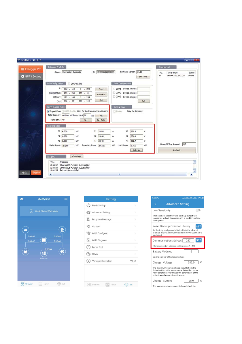
3.3.5.1 SEC1000S Anti Reverse Current Function
On “DRED & ARCB Setting”part, enter total capacity of the paralleling system and ratio of CT
(external) and power limit into grid.
Note: the above steps are mandatory to set up the whole system.
Please check the option "Export Enable" if you want to apply export power limit function in your
system.with this function enabled, you can monitor real-time data of grid connection such as output
active power, output current, and output voltage.
3.3.5.2 PV Master conguration for paralleling application (inverter)
You should set communication address for every inverter in the paralleling system, and the address
should be dierent from each other. For example, you may set the address for each inverter from 1 to
10 if there are 10 inverters in the paralleling system. The ID of inverter connected to the communication
port should not be duplicate. To monitoring the whole system, all inverters should be registered under
the same power plant on GoodWe monitoring platform SEMS Portal.
09
Page 12
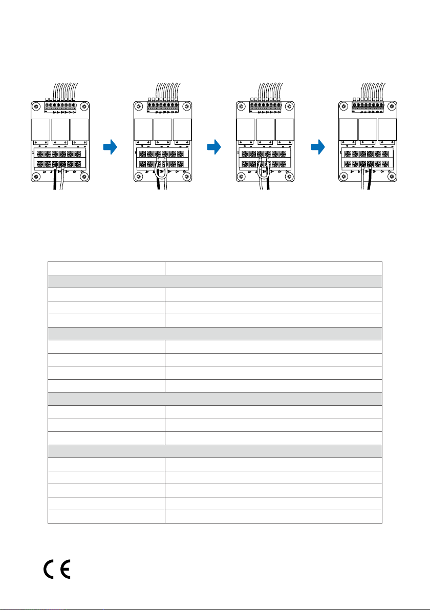
4 Troubleshooting
If the external CT current is connected in the wrong direction, please reconnect it.
Take the reversed CT current connection of B + and B- as an example to introduce the correcting
method, as shown below:
1.B+ and B- connected
reversed
Note: When replacing the meter, all 3 groups of CTs need to be short-circuited.
2.Add a cable between B+ and
B- to short-circuit them
3.Correct connection of
B+ and B-
5 Technology parameter
Model SEC1000S
Communication
Max. Inverters Supported
RS485 interface
Ethernet
Conguration
Datalogger
Meter
Power Supply
Power Consumption (W)
Mechanical
Dimensions (W×H×D mm)
Weight (kg)
Installation Method
Environment
Operating Temperature Range (℃)
Storage Temperature Range(℃)
Relative Humidity
Max. Operating Altitude (m)
Ingress Protection Rating
1*RJ45, 10/100 Mbps
100–280Vac, 50/60 Hz
Wall mounting, bracket mounting, pole mounting
0-100% (non-condensing)
20
Ezlogger*1
GM3000*1
≤10
350*460*143
-25 ~ 60°C
-40 ~ 70°C
2000
IP65
4.Remove the short
cable
3
6
6 Relevant Certication
10
Page 13
GoodWe Website
GoodWe Technologies Co., Ltd.
No. 90 Zijin Rd., New District, Suzhou, 215011, China
www.goodwe.com
Local Contacts340-00711-01
 Loading...