

Page 1

MT Series (50kW~75kW)
INTRODUCTION
© copy right reserved by GoodWe
Page 2
Contents
Product Overview
Development Background
New Product Feature
Installation Guide
Internal Structure
Trouble Shooting
© copy right reserved by GoodWe
Technical Data
Monitoring Configuration
Certifications
Page 3

Contents
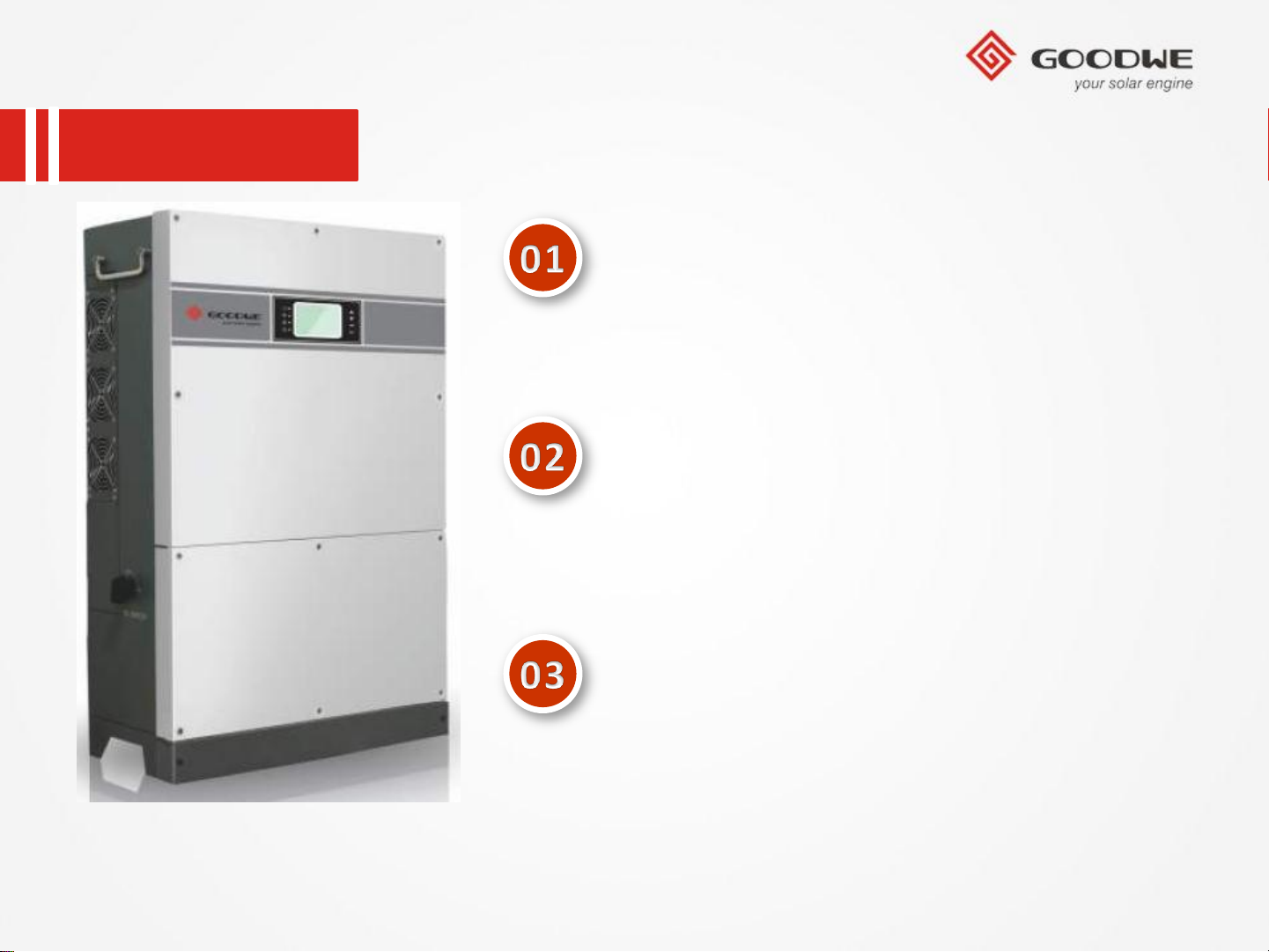
Product Overview
Development Background
New Product Feature
Installation Guide
Internal Structure
Trouble Shooting
© copy right reserved by GoodWe
Technical Data
Monitoring Configuration
Certifications
Page 4
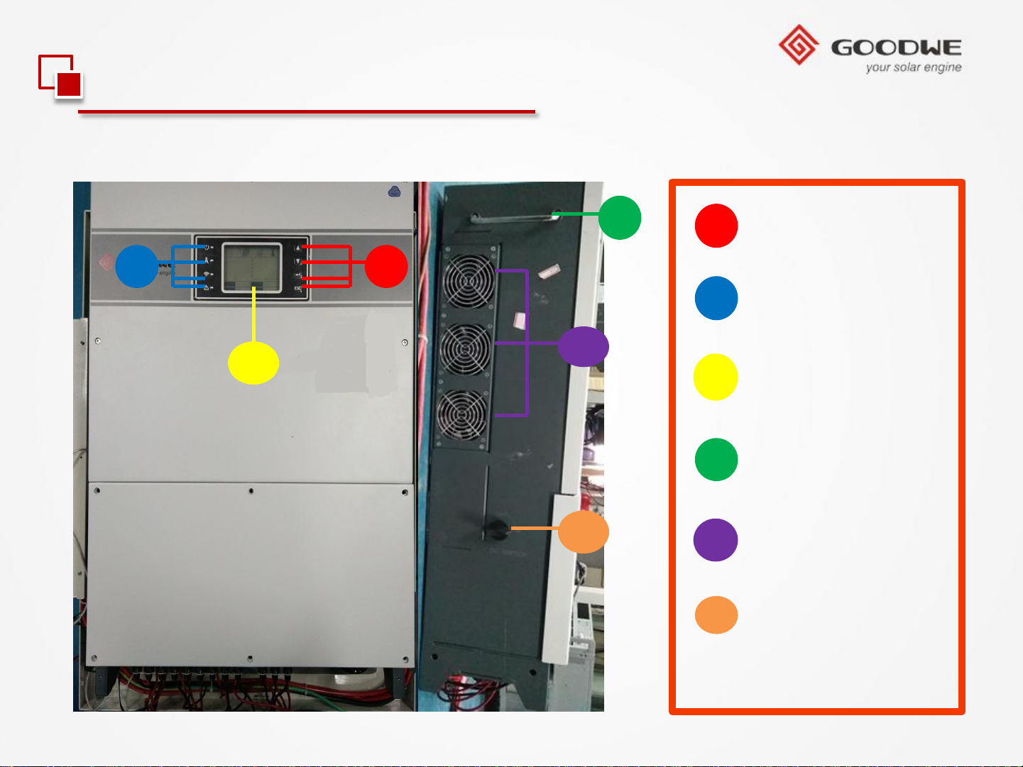
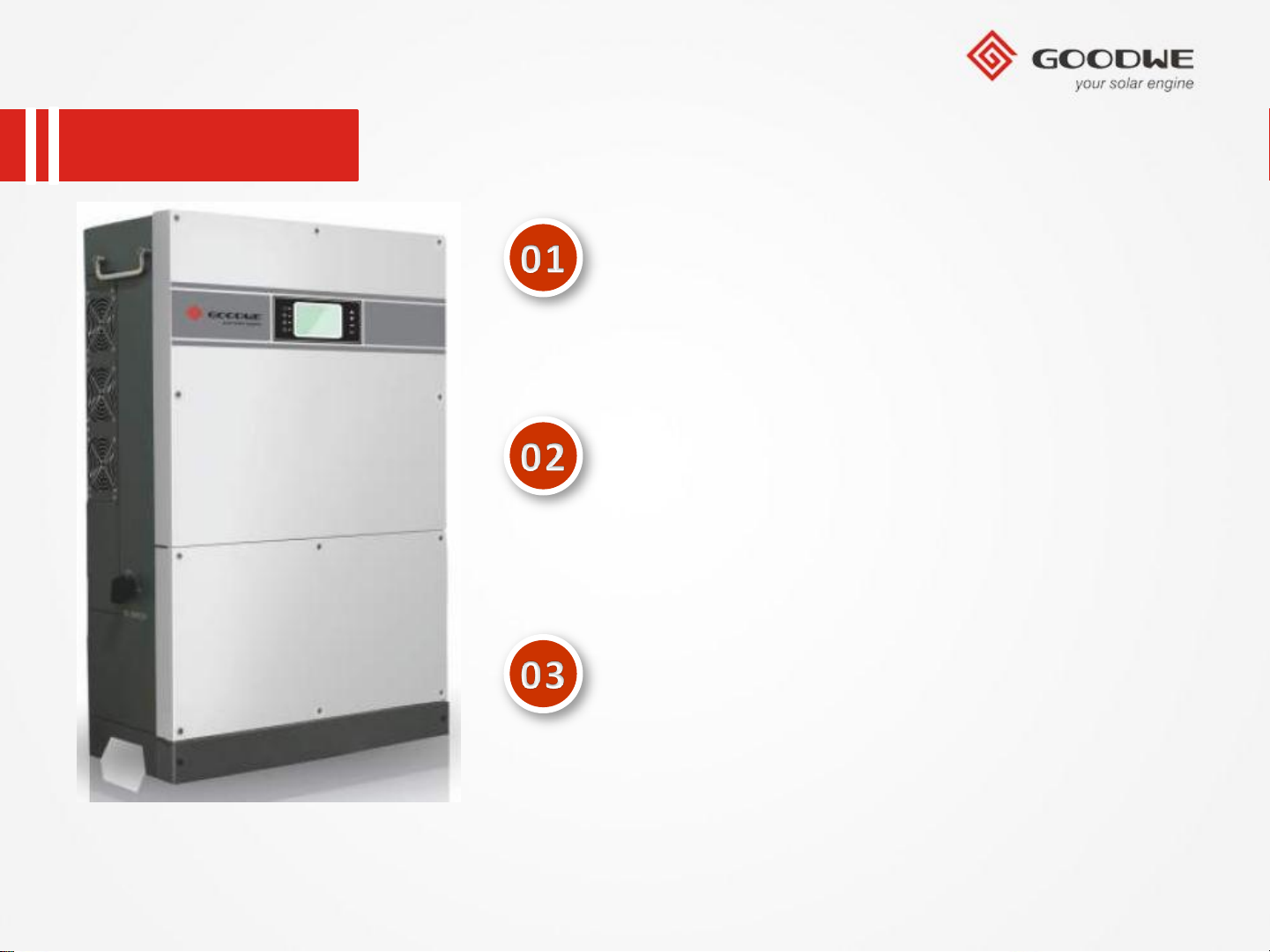
1.1 Product Overview
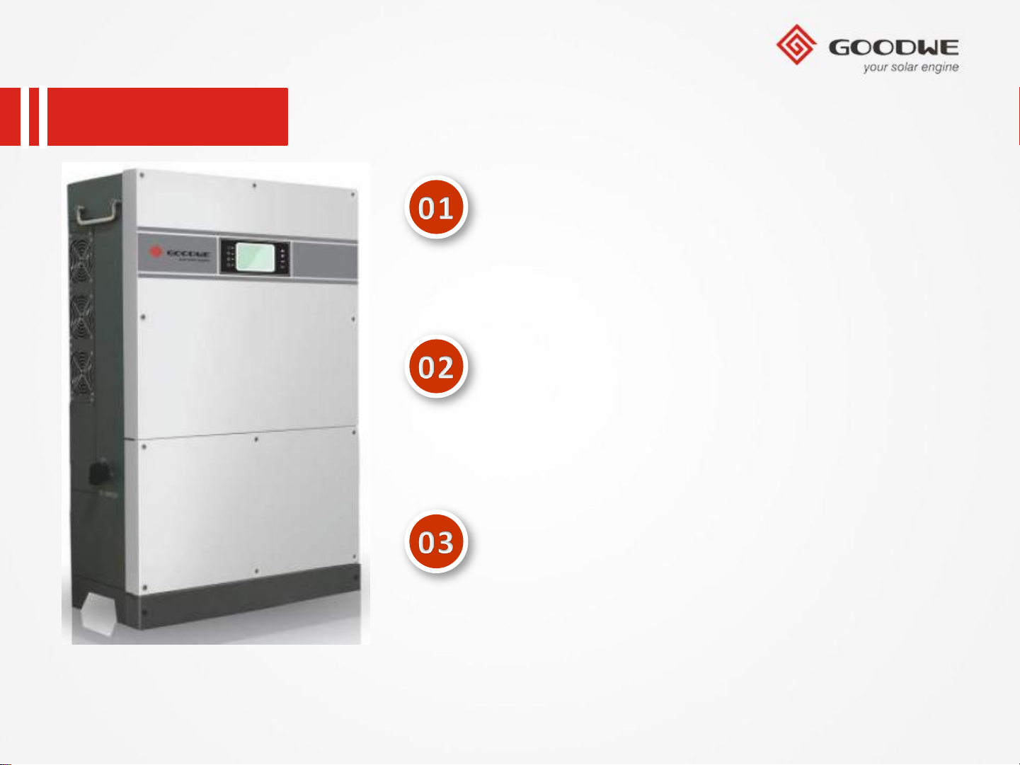
• MT Series Overview (50kW~75kW)
3
4
1
Buttons
1 2
2
Pilot Lamp
5
6
3
4
5
6
LCD Display
Handle
Cooling Fans
DC Switch
© copy right reserved by GoodWe
Page 5
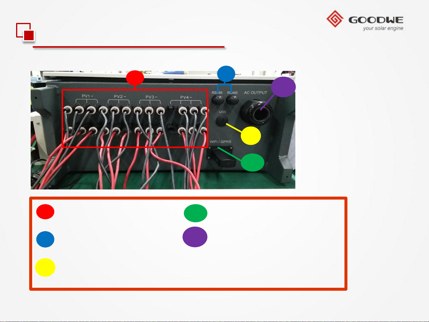
1.1 Product Overview
• MT Series Overview (50kW~75kW)
7
PV Input Terminals
8
RS485 Port
7
10
11
8
11
9
10
WiFi/GPRS Port
AC Output Terminal
USB Port
9
© copy right reserved by GoodWe
Page 6
Contents
Product Overview
Development Background
New Product Feature
Installation Guide
Internal Structure
Trouble Shooting
© copy right reserved by GoodWe
Technical Data
Monitoring Configuration
Certifications
Page 7
1.2 Development Background
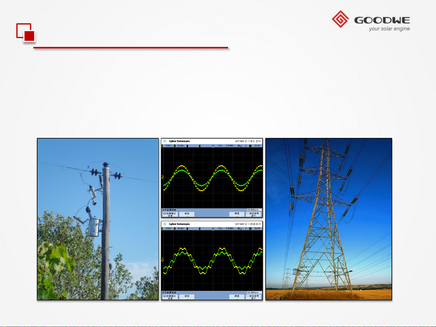
Different regions in various countries in the world,the power grids were different;
An excellent inverter must have the power grid anti-interference ability;
Meanwhile ,the output current harmonic wave,PF and DCI value must conform to
different regions in different countries’ laws and regulations requirement.
© copy right reserved by GoodWe
Page 8
Contents
Product Overview
Development Background
New Product Feature
Installation Guide
Internal Structure
Trouble Shooting
© copy right reserved by GoodWe
Technical Data
Monitoring Configuration
Certifications
Page 9
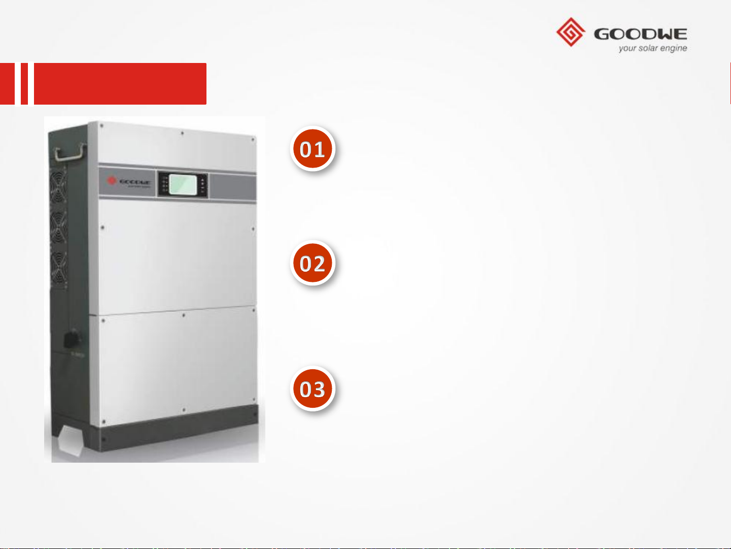
1.3 New Product Feature
1
5
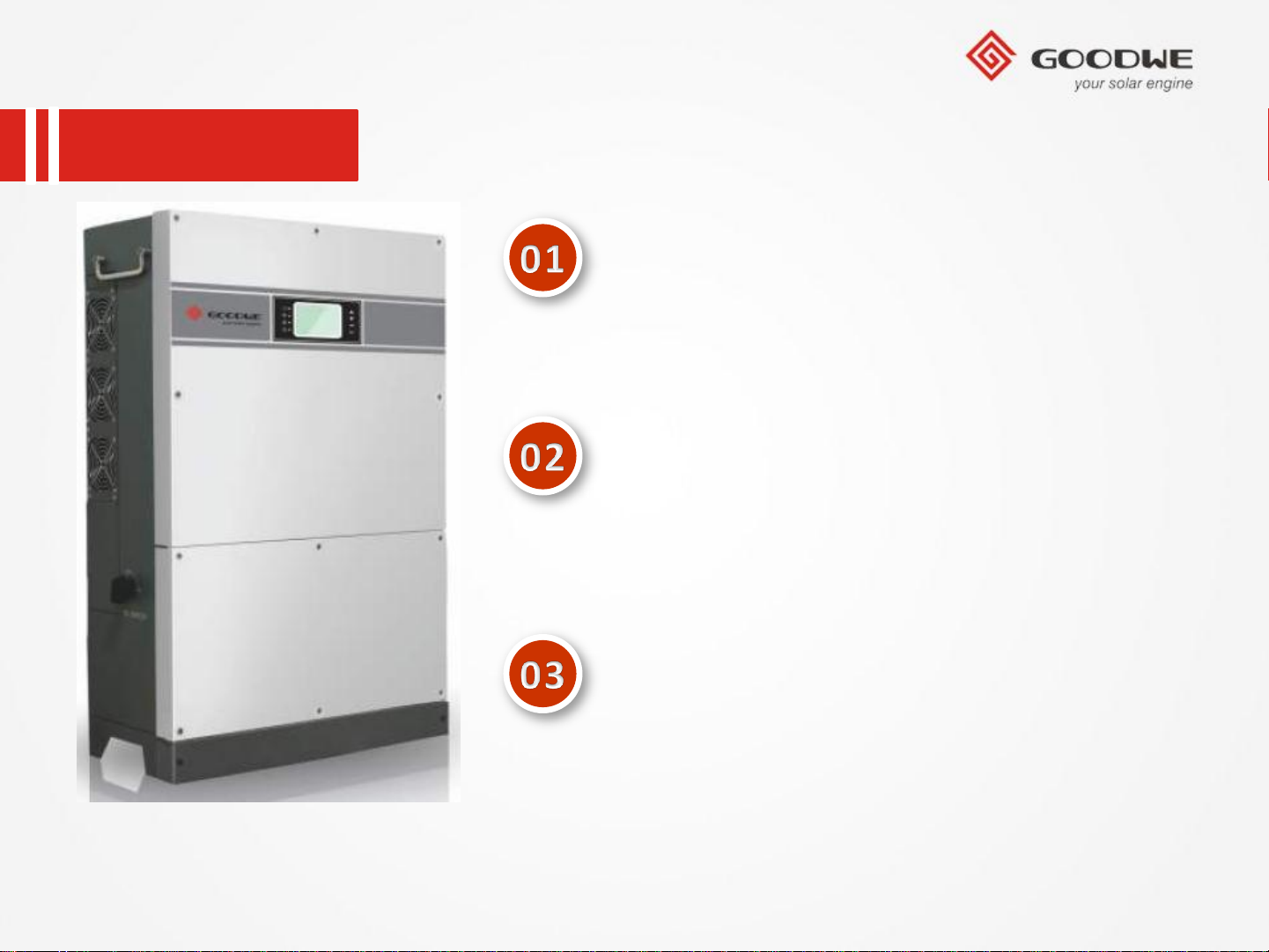
Four MPP Trackers
2
3
4
Type Ⅱanti-thunder for AC & DC
Support RS485 & WiFi & GPRS communication
IP68 level fans
5 inch multi-function screen
© copy right reserved by GoodWe
Page 10
Contents
Product Overview
Development Background
New Product Feature
Installation Guide
Internal Structure
Trouble Shooting
© copy right reserved by GoodWe
Technical Data
Monitoring Configuration
Certifications
Page 11
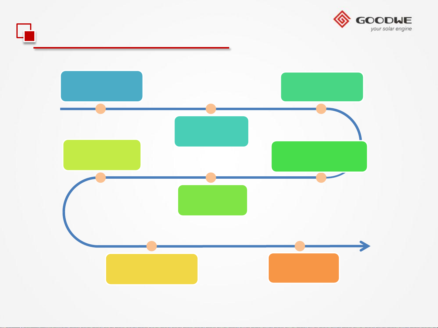
2.1 Installation Guide
1.Open package
and check
6.RS485 wires
installation
3.Installation
instructions
2.Accessory
package
4.Connection to Grid
(AC Side Connection)
5.DC Side
Connection
© copy right reserved by GoodWe
7.WiFi / GPRS
module installation
8.Monitoring
Configuration
Page 12
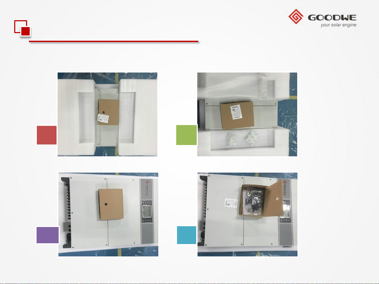
2.1 Installation Guide
1.Open package and check
1 2
3 4
© copy right reserved by GoodWe
Page 13

2.1 Installation Guide
2.Accessory package
© copy right reserved by GoodWe
Page 14
2.1 Installation Guide
3.Installation instructions
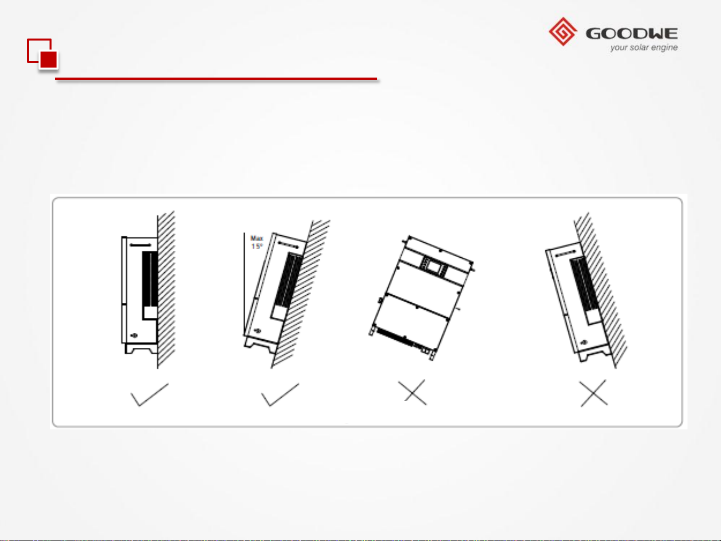
Carry out the installation vertically or tilt backward no more than 15 degrees, no lateral
tilt, and wiring area should be downward, which is shown in below picture.
© copy right reserved by GoodWe
Page 15
2.1 Installation Guide
3.Installation instructions
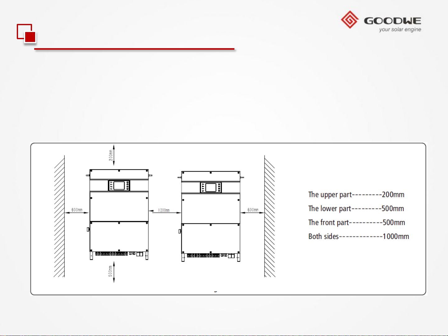
To ensure the good heat dissipation and convenient disassembly, the minimum gap
around the inverter should not be less than the following values, which are shown in
below picture.
© copy right reserved by GoodWe
Page 16
2.1 Installation Guide
3.Installation instructions
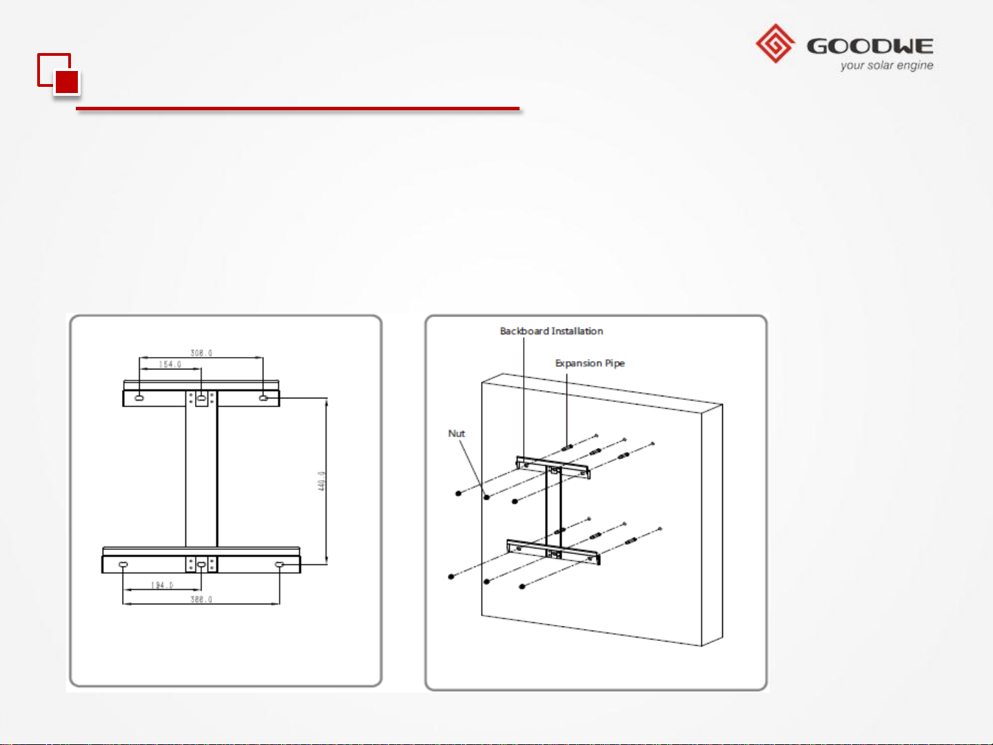
(1) Drill 6 holes on the wall with the backboard as template positioning, whose
diameter is 13mm , depth is 65mm; the size of MT model is shown in below pictures.
(2) Fix the backboard on the wall with the expansion screws in accessory bag.
© copy right reserved by GoodWe
Page 17
2.1 Installation Guide
3.Installation instructions
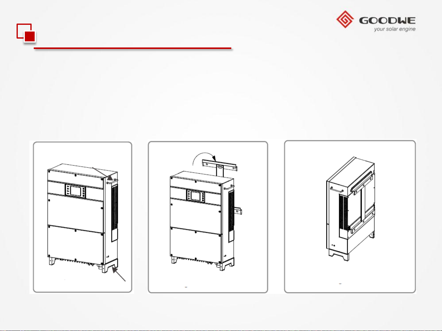
(3) Carry the inverter with the handles on both sides of the inverter of MT series, which
is shown in below pictures.
(4) Hang the inverter on the backboard, which is shown in below pictures.
© copy right reserved by GoodWe
Page 18
2.1 Installation Guide
4.Connection to Grid (AC Side Connection)
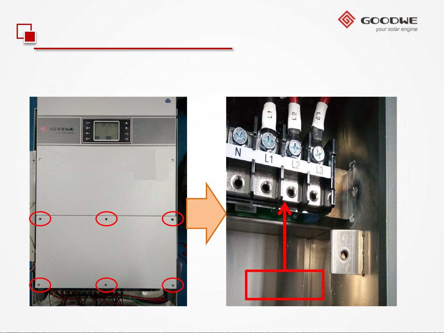
Unscrew the inverter’s downside cover and take it way.
© copy right reserved by GoodWe
AC Side
Page 19
2.1 Installation Guide
4.Connection to Grid (AC Side Connection)
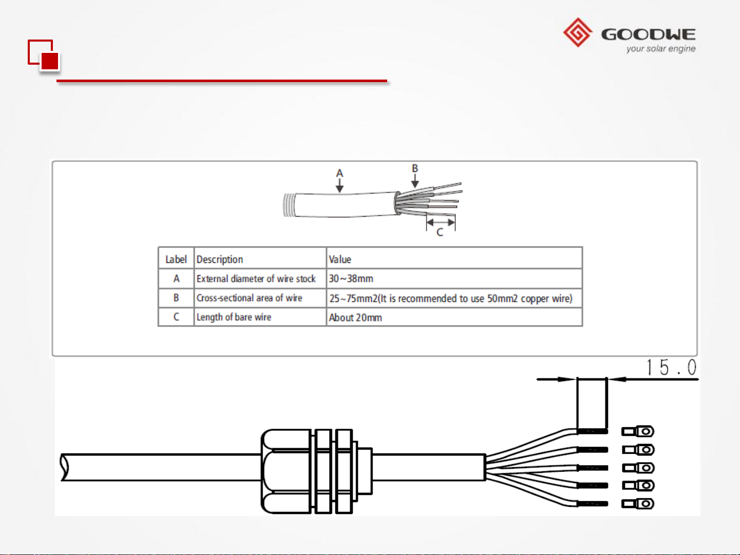
Cable specifications of AC electric wire are shown in pictures.
© copy right reserved by GoodWe
Page 20
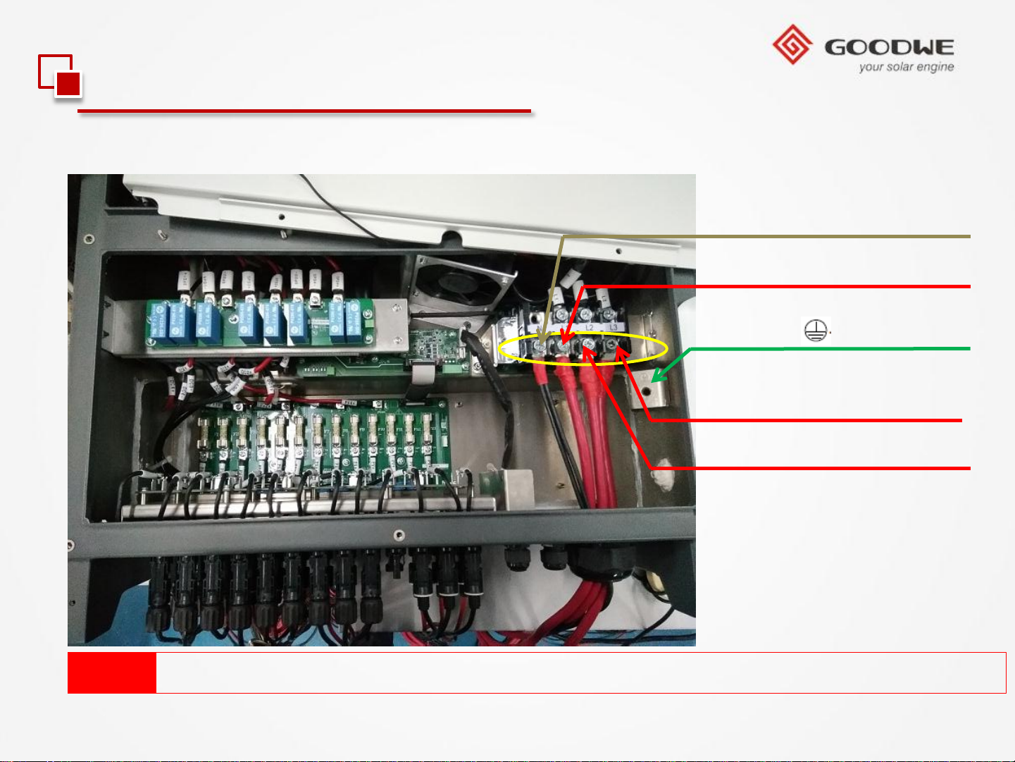
2.1 Installation Guide
4.Connection to Grid (AC Side Connection)
N---Null Line
L1---Live Wire 1
---Earth Wire
L2---Live Wire 2
L3---Live Wire 3
Note: The N line of GW65KHV-MT / GW75KHV-MT should not be connected.
© copy right reserved by GoodWe
Page 21
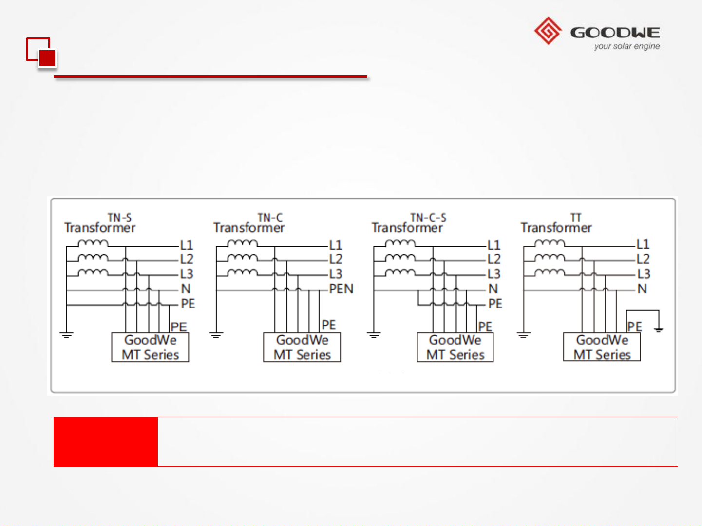
2.1 Installation Guide
4.Connection to Grid (AC Side Connection)
Supported power grid forms:
The power grid forms supported by the three-phase machine type of GW50KMT/GW60K-MT series include TN-S, TN-C, TN-C-S, and TT, as shown in below picture.
Note:
© copy right reserved by GoodWe
For TT power grid form, the effective value of voltage between the null
line and the earth wire is less than 20V.
Page 22
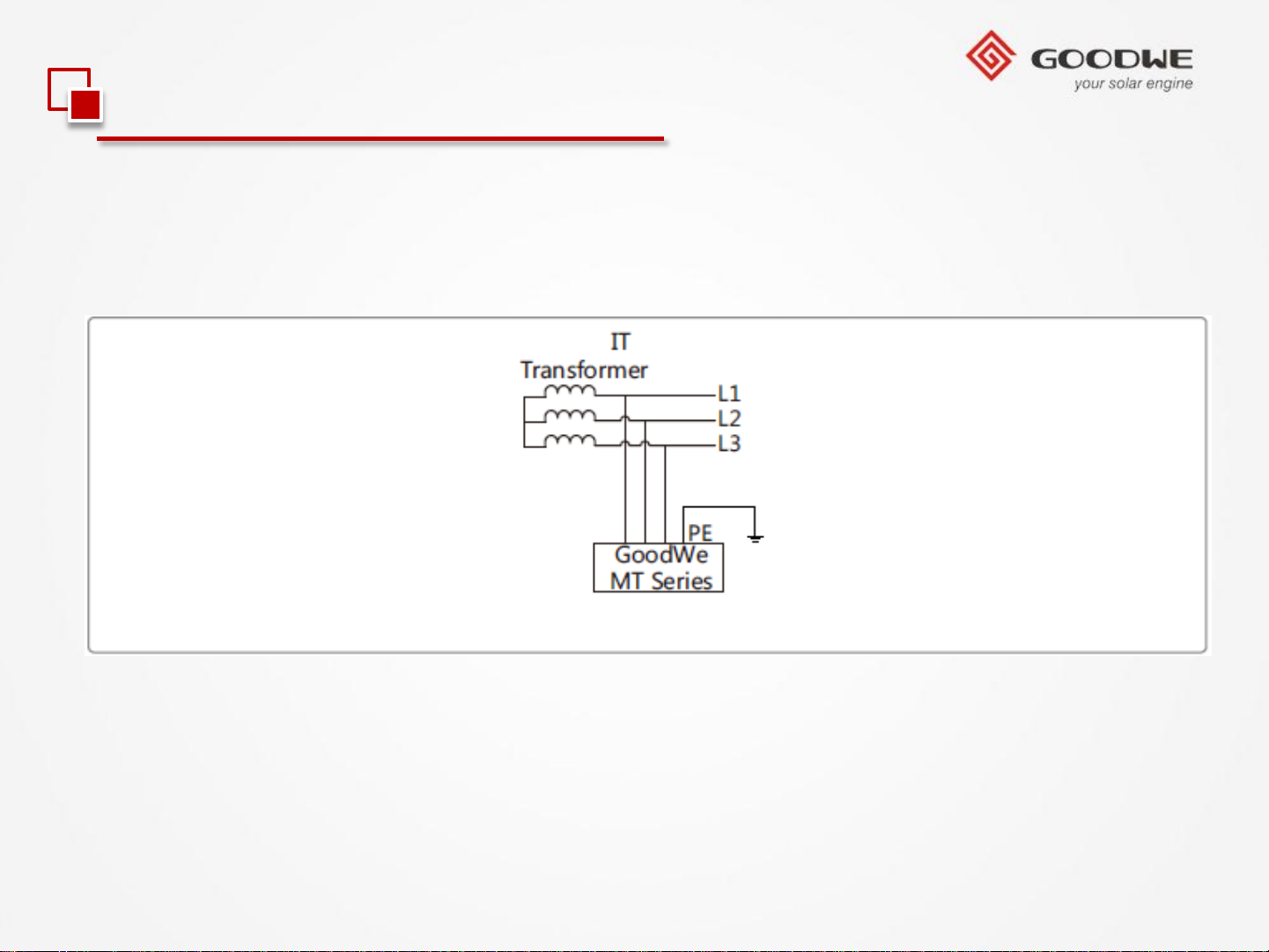
2.1 Installation Guide
4.Connection to Grid (AC Side Connection)
The power grid form supported by the three-phase machine type of GW65KHVMT/GW75KHV-MT series is IT, as shown in below picture.
© copy right reserved by GoodWe
Page 23
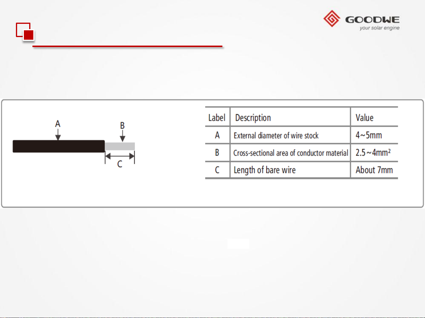
2.1 Installation Guide
5.DC Side Connection
Cable specifications of DC electric wire are shown in below picture.
© copy right reserved by GoodWe
Page 24
2.1 Installation Guide
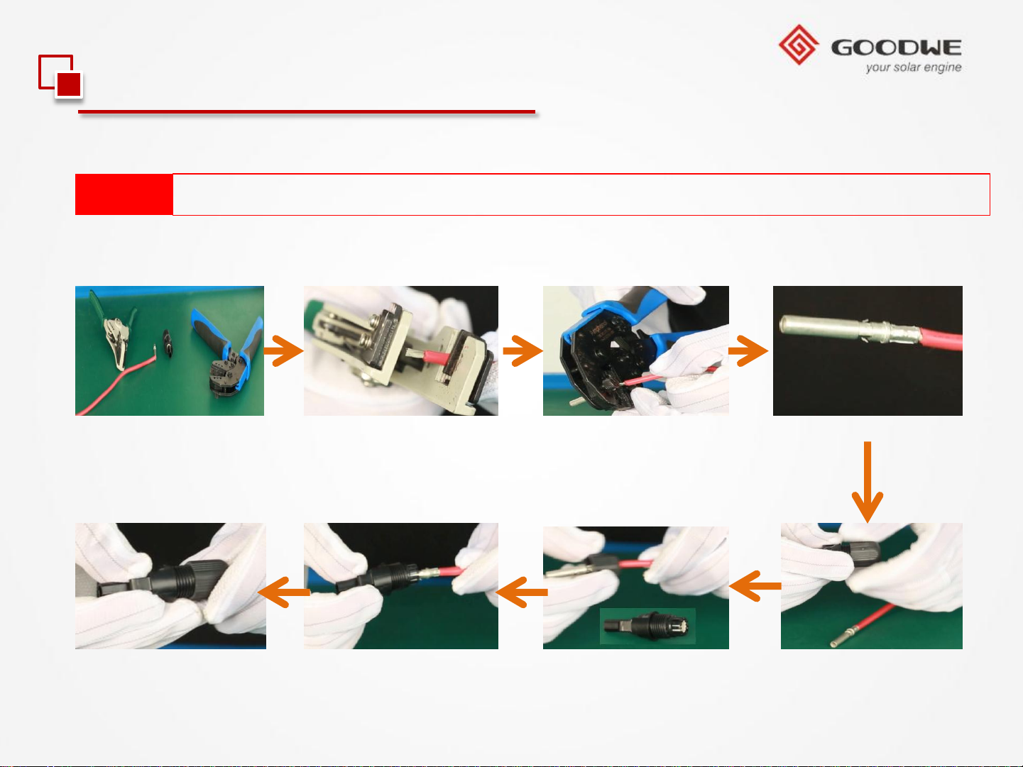
5.DC Side Connection
Note:
Before connecting PV string, make sure DC switch is turned off.
Installation instruction of PV+ wire of MC4 connectors please refer to below pictures.
Step 1
Step 2
Step 4 Step 3
Step 8
© copy right reserved by GoodWe
Step 7 Step 6
Step 5
Page 25
2.1 Installation Guide
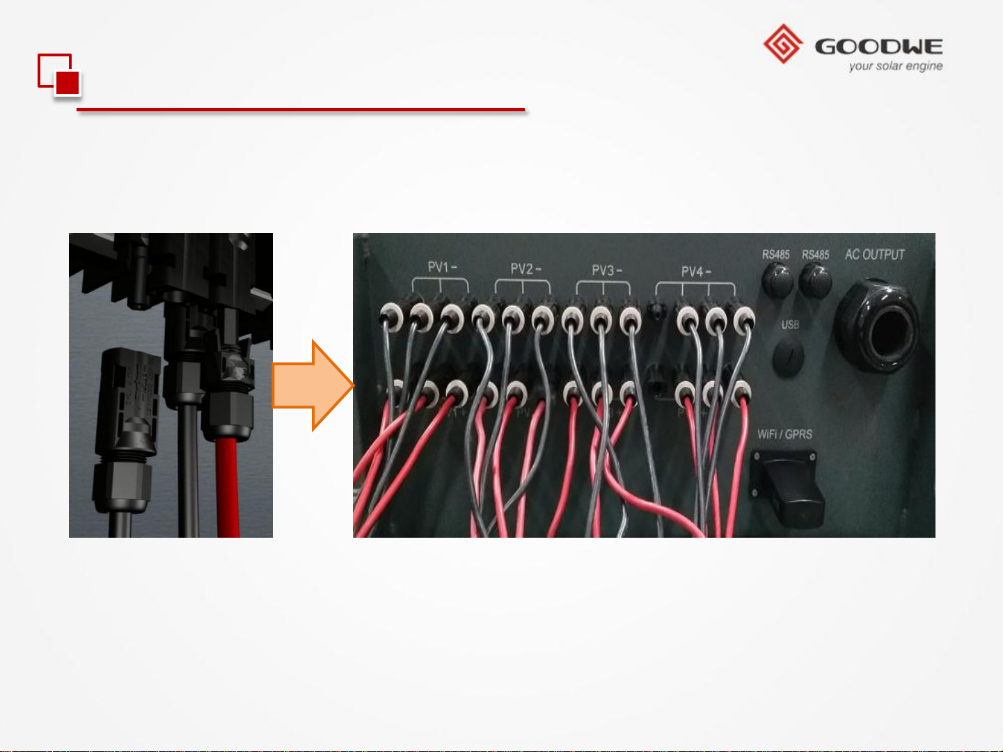
5.DC Side Connection
Installation instruction of PV- wire of MC4 connectors is the same with PV+ wire.
© copy right reserved by GoodWe
Page 26
2.1 Installation Guide
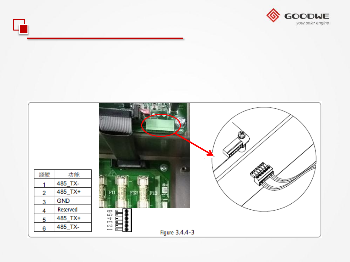
6.RS485 wires installation
This function only applies to inverter with RS485 ports and communication lines must be
separated from other power lines to avoid communication interference.
© copy right reserved by GoodWe
Page 27
2.1 Installation Guide
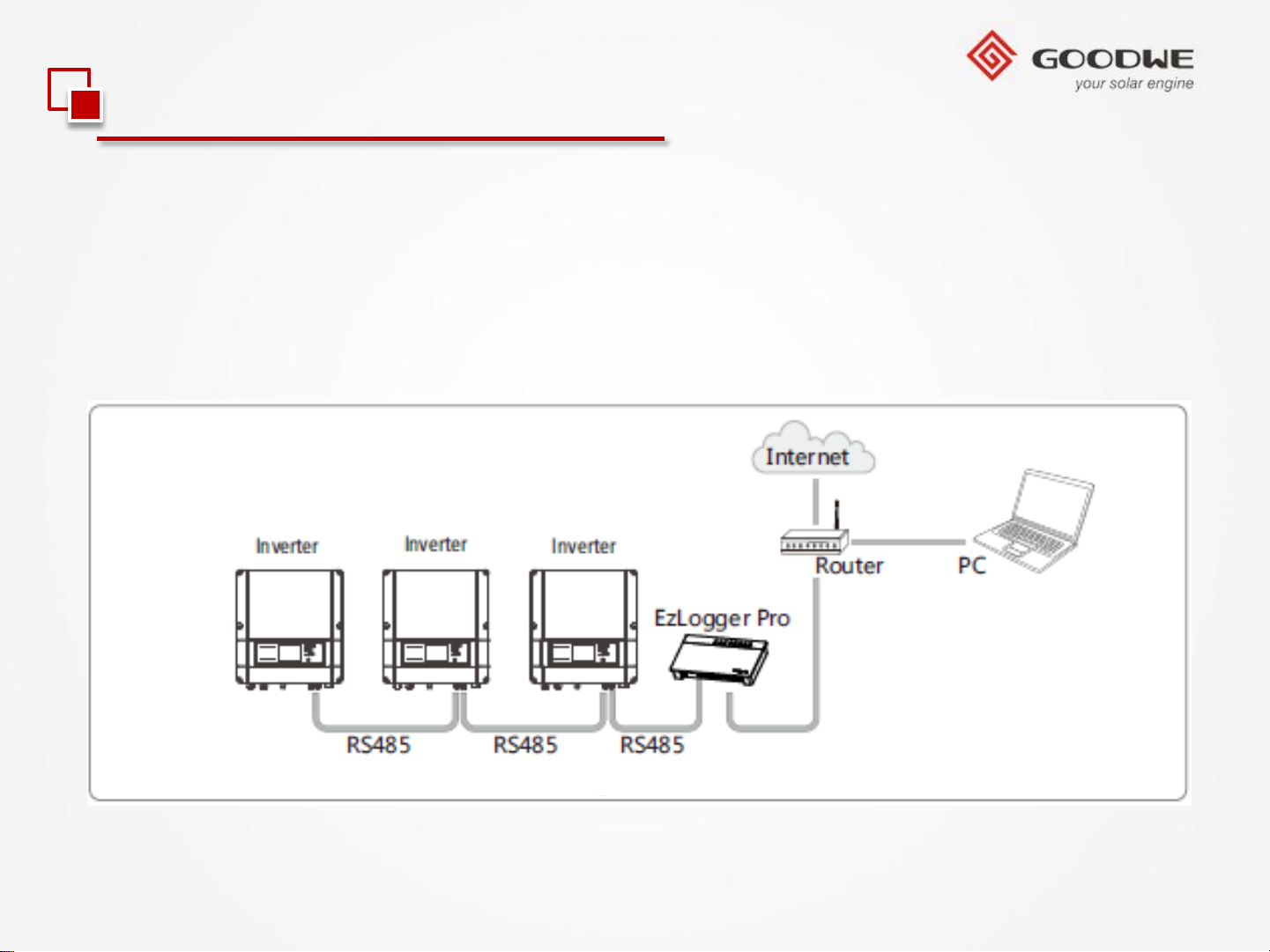
6.RS485 wires installation
The RS485 interface is used to connect EzLogger Pro only, please make sure the
connecting cables not exceed 1000m.
RS485 connection please refer to below picture.
© copy right reserved by GoodWe
Page 28
2.1 Installation Guide
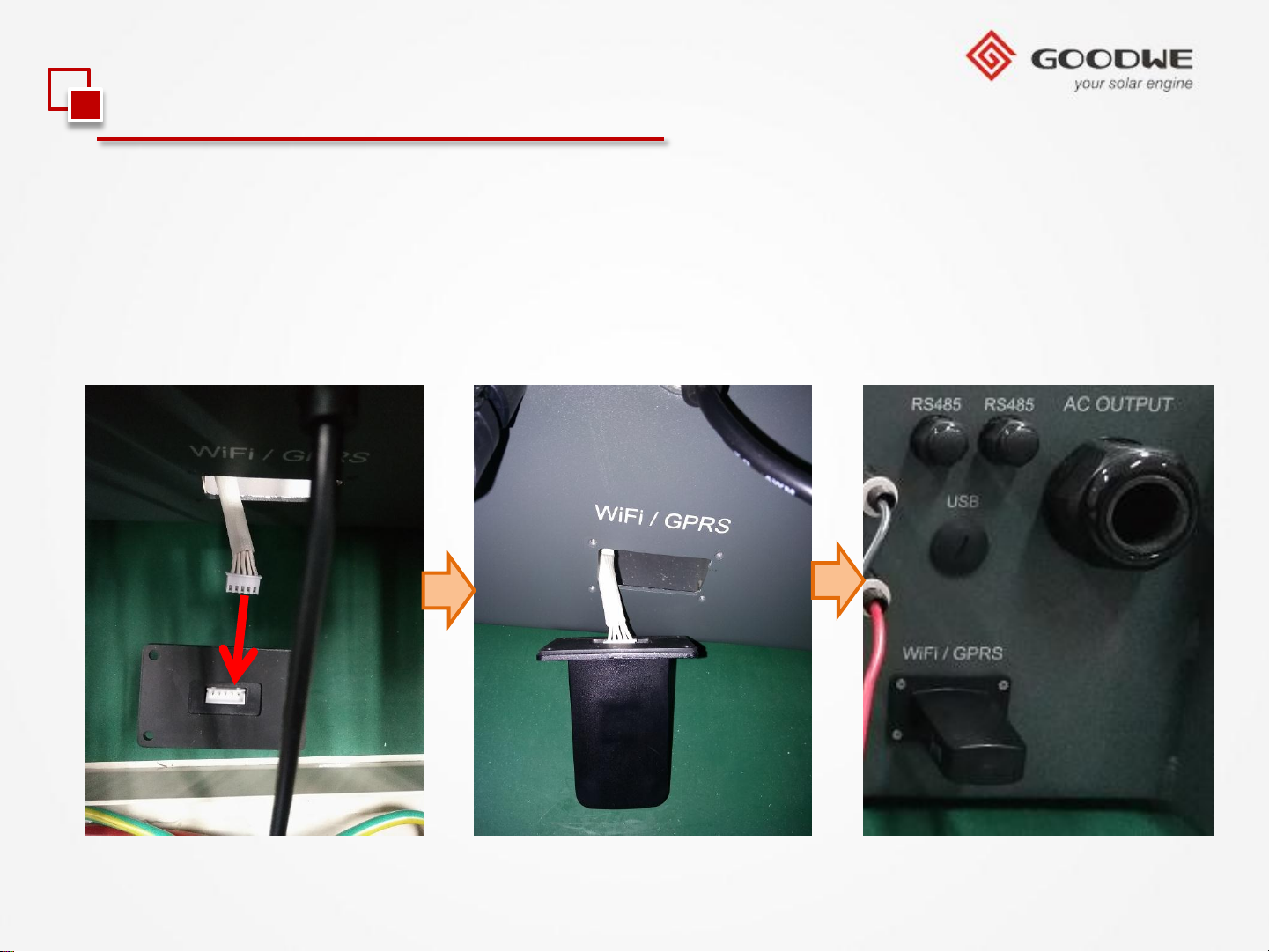
7.WiFi / GPRS module installation
If your inverter is WiFi / GPRS communication , please refer to below installation guide
for WiFi / GPRS module:
1).Connect the white 5 pins connector to WiFi / GPRS module as picture a & b showed
and fix the WiFi / GPRS module on the inverter as picture c showed.
a b c
© copy right reserved by GoodWe
Page 29
2.1 Installation Guide
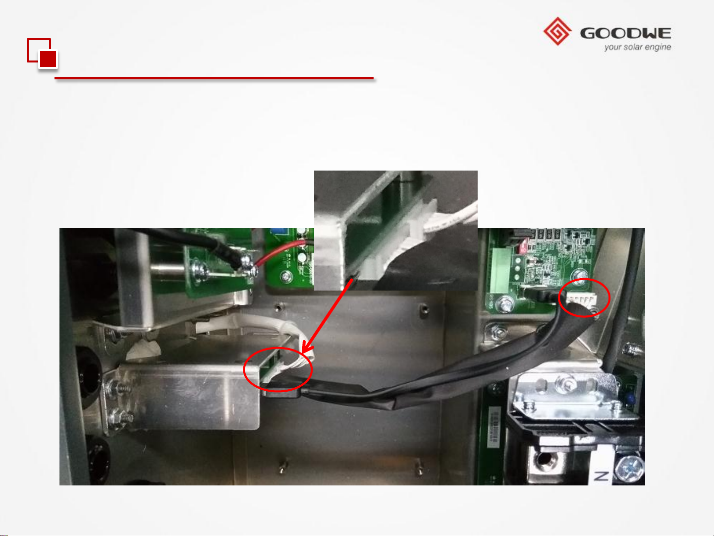
7.WiFi / GPRS module installation
2).Check the connection inside the inverter as below picture showed.
© copy right reserved by GoodWe
Page 30
Contents
Product Overview
Development Background
New Product Feature
Installation Guide
Internal Structure
Trouble Shooting
© copy right reserved by GoodWe
Technical Data
Monitoring Configuration
Certifications
Page 31
2.2 Internal Structure
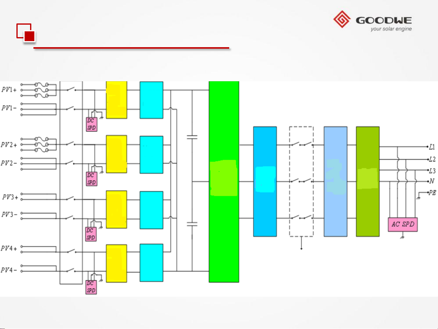
Block Diagram of MT series inverter.
Input
EMI
Filter
Input
EMI
Filter
Input
EMI
Filter
Input
EMI
Filter
MPPT
Circuit1
MPPT
Circuit2
MPPT
Circuit3
MPPT
Circuit4
DC/AC
LC
Filter
Output
EMI
Filter
Output Isolation Relay
L
Filter
DC Switch
© copy right reserved by GoodWe
Page 32
Contents
Product Overview
Development Background
New Product Feature
Installation Guide
Internal Structure
Trouble Shooting
© copy right reserved by GoodWe
Technical Data
Monitoring Configuration
Certifications
Page 33
2.3 Trouble Shooting
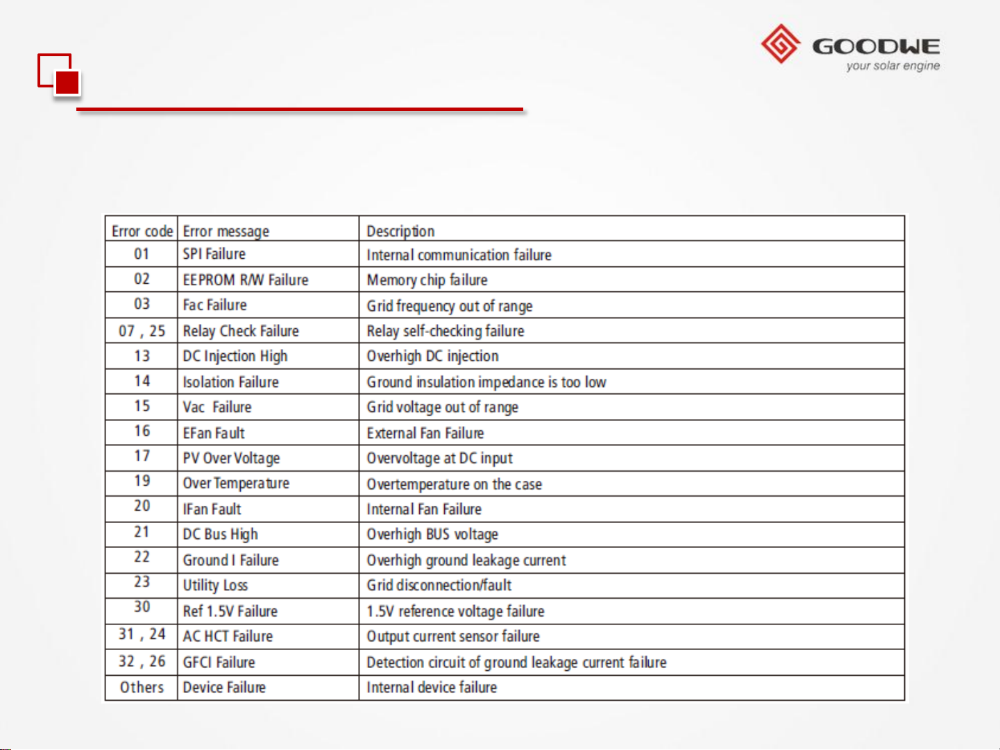
Error Code
The error message in below diagram will be displayed on the LCD if a fault occurs.
© copy right reserved by GoodWe
Page 34
2.3 Trouble Shooting
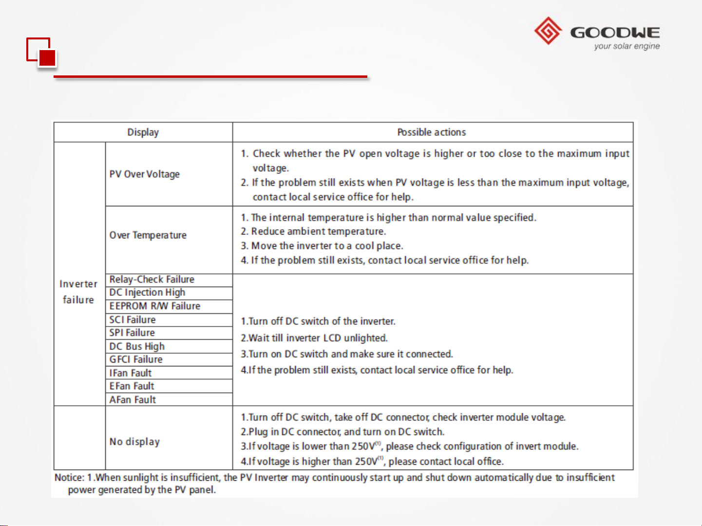
Troubleshooting
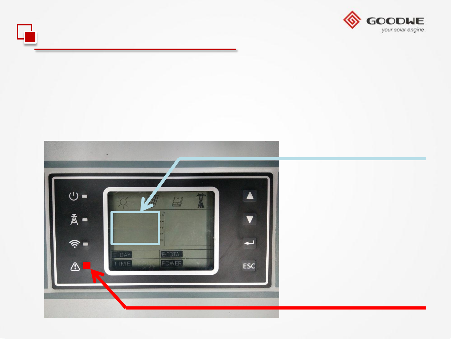
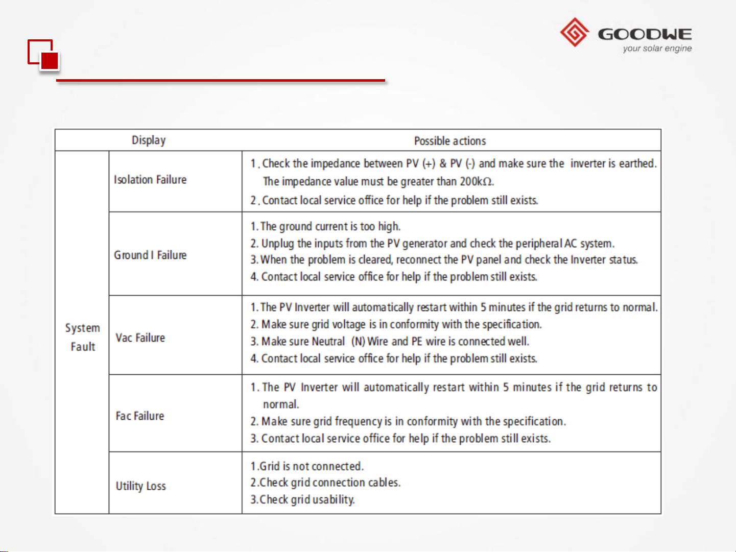
Should any problems arise, the red (FAULT) LED indicator on the front panel lights up
and the LCD screen will display relevant information. Please refer to the following
table for a list of error message and associated solutions.
Error message display area
© copy right reserved by GoodWe
The red LED lights up
Page 35
2.3 Trouble Shooting
Troubleshooting
© copy right reserved by GoodWe
Page 36
2.3 Trouble Shooting
Troubleshooting
© copy right reserved by GoodWe
Page 37
Contents
Product Overview
Development Background
New Product Feature
Installation Guide
Internal Structure
Trouble Shooting
© copy right reserved by GoodWe
Technical Data
Monitoring Configuration
Certifications
Page 38

Model
DC
Max. allowed PV Power (W)
Nominal. DC power (W)
Max. DC voltage (V)
MPPT voltage range (V)
Starting
Max
No
No
AC
Norminal
Max
Max
Norminal
AC
Power
THDi
Grid
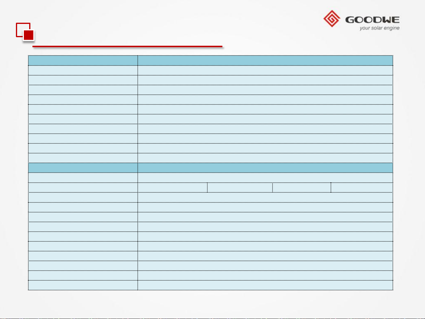
3.1 Technical Data — MT Series
Max
Euro
MPPT
GW50K-MT GW60K-MT GW65KHV-MT GW75KHV-MT
Input
voltage (V)
. DC current (A)
. of DC connectors
. of MPPTs
Output
AC power(W)
. AC power(W)
. AC current(A) 80 90 80 90
AC output
output range
65000 75000 75000 80000
51500 62000 67000 77000
1000 1000 1000 1000
260~850 260~850 260~850 260~850
250 250 250 250
28 / 28 / 19 / 19 28 / 28 / 28 / 28 28 / 28 / 28 / 28 28 / 28 / 28 / 36
10 12 12 13
4 4 4 4
50000 60000 65000 75000
55000 62100 66480 75000
50/60Hz; 400Vac 50/60Hz; 480Vac
45~55Hz/55~65Hz; 310~480Vac 45~55Hz/55~65Hz; 422~528Vac
factor
connection
. efficiency
© copy right reserved by GoodWe
efficiency
adaptation efficiency
0.80leading…0.80lagging
<3%
3W/N/PE 3W/N/PE 3W/PE 3W/PE
98.70% 98.8% 98.8% 98.8%
98.3% 98.5% 98.5% 98.5%
99.90% 99.90% 99.90% 99.90%
Page 39
Protection
Residual
PV array string fault monitoring
Anti
DC Fuse
DC
DC SPD
AC SPD
SPD fault monitoring
AC
Insulation
General Data
Dimensions
Weight
Mounting
Ambient
Relative
Max
Protection
Topology
Cooling
Display
Communication
Standard
3.1 Technical Data — MT Series
current monitoring unit
-islanding protection
switch
over current protection
monitoring
(WxHxD)
(kg)
temperature range
humidity
. operating altitude
degree
warranty(years)
Integrated
66 68 68 68
USB2.0; RS485; WiFi/GPRS/LAN; Bluetooth
5/10/15/20/25 (Optional)
Integrated
Integrated (Optional)
Integrated
Integrated (Optional)
Type II
Type II(optional)
Integrated
Integrated
Integrated
586*915*263mm
Wall Bracket
-25~60℃
0~95%
4000m
IP65
Transformerless
Fan cooling
LCD
© copy right reserved by GoodWe
Page 40
Contents
Product Overview
Development Background
New Product Feature
Installation Guide
Internal Structure
Trouble Shooting
© copy right reserved by GoodWe
Technical Data
Monitoring Configuration
Certifications
Page 41
3.2 Monitoring Configuration
1.WiFi Inverter (Via laptop/Pad)
1). Preparation
1.1). Power WiFi inverter (or EzLogger Pro WiFi) on.
1.2). If you are configuring WiFi inverter, make sure the yellow LED on front cover is
blinking. Otherwise please set the communication to WiFi according to user manual of
inverter at first.
1.3). Power WiFi router on.
1.4). Switch on the WiFi of laptop.
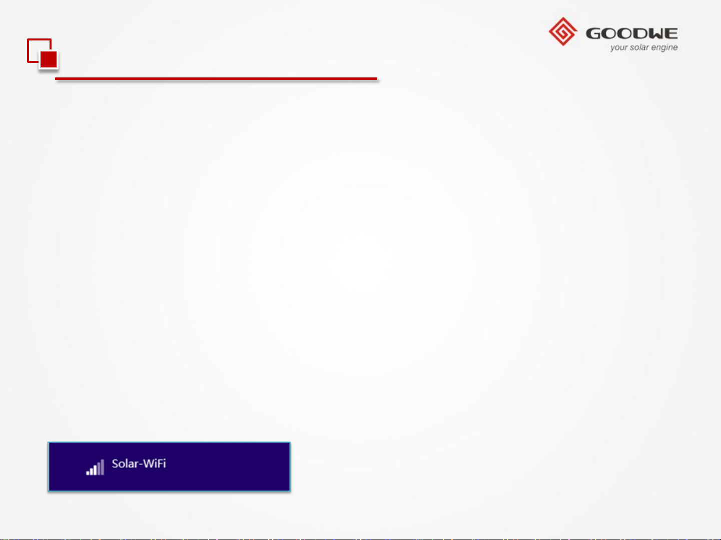
2). Connect laptop to “Solar-WiFi”
2.1). Search WiFi network and connect to “Solar-WiFi” (Password: 12345678).
© copy right reserved by GoodWe
Page 42
3.2 Monitoring Configuration
1.WiFi Inverter (Via laptop/Pad)
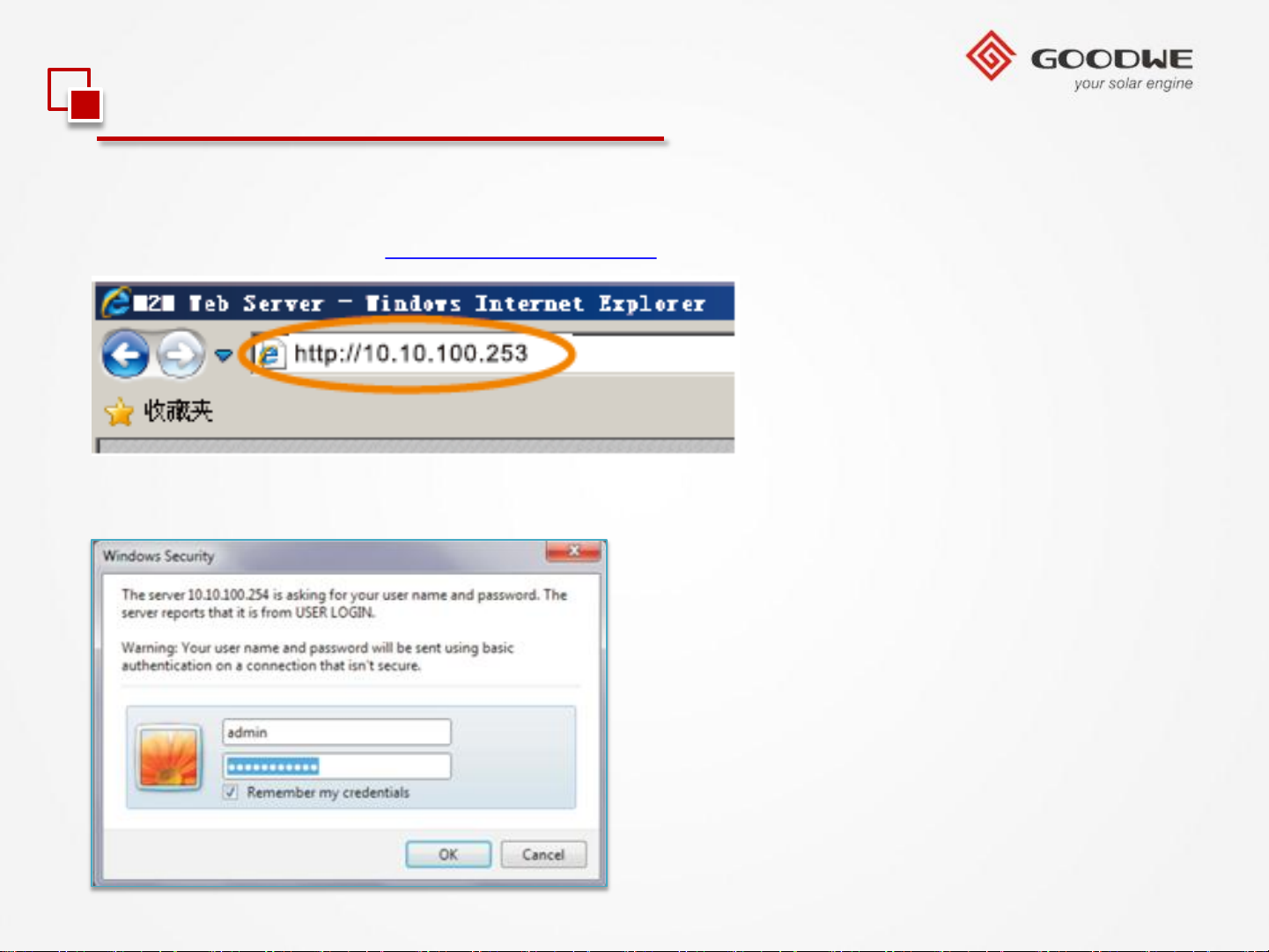
2.2). Browse website: http://10.10.100.253
2.3). Enter User Name: “admin”, Password: “admin”.
© copy right reserved by GoodWe
Page 43
3.2 Monitoring Configuration
1.WiFi Inverter (Via laptop/Pad)
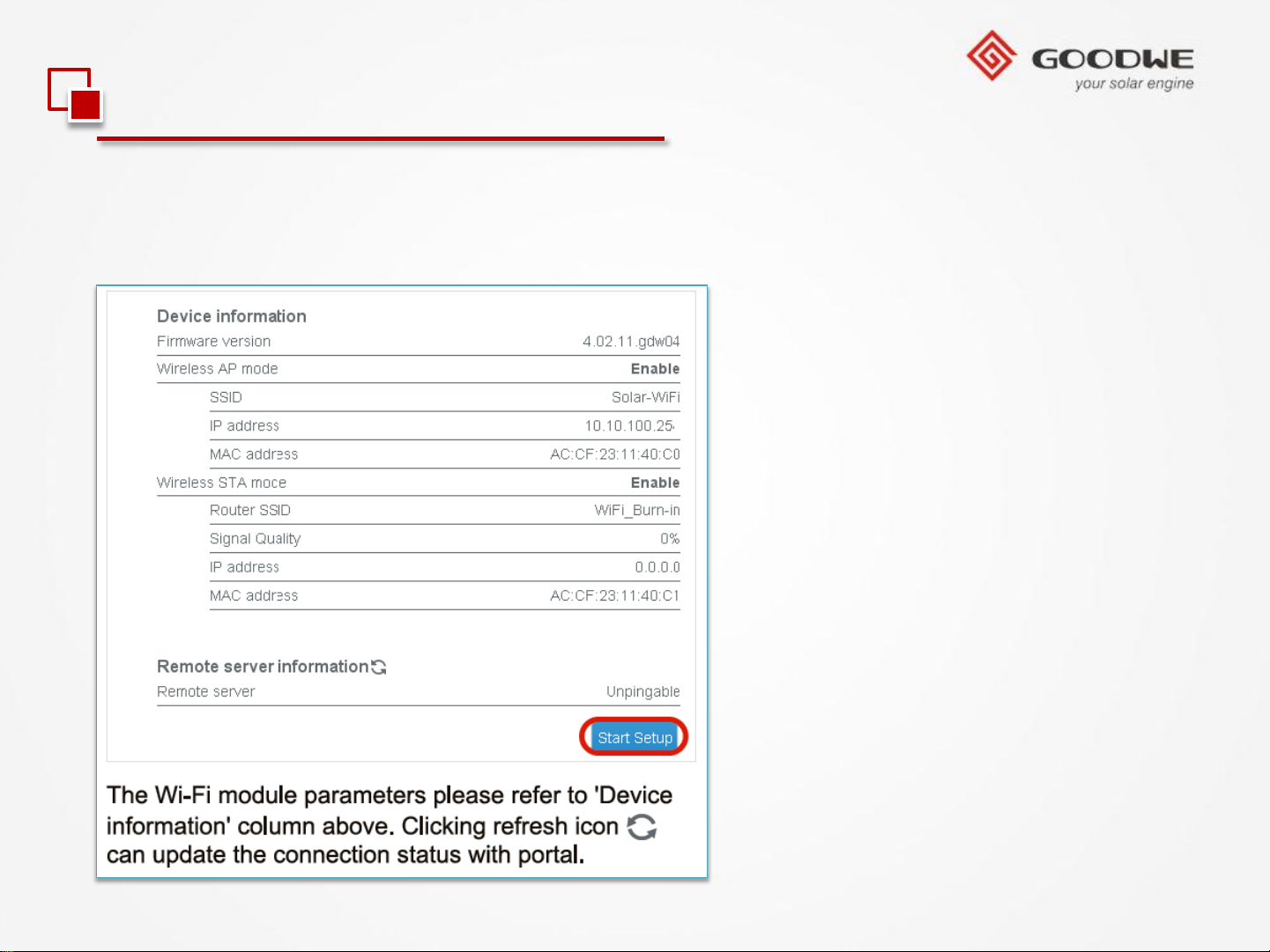
3). Click ‘Start Setup’
3
© copy right reserved by GoodWe
Page 44
3.2 Monitoring Configuration
1.WiFi Inverter (Via laptop/Pad)
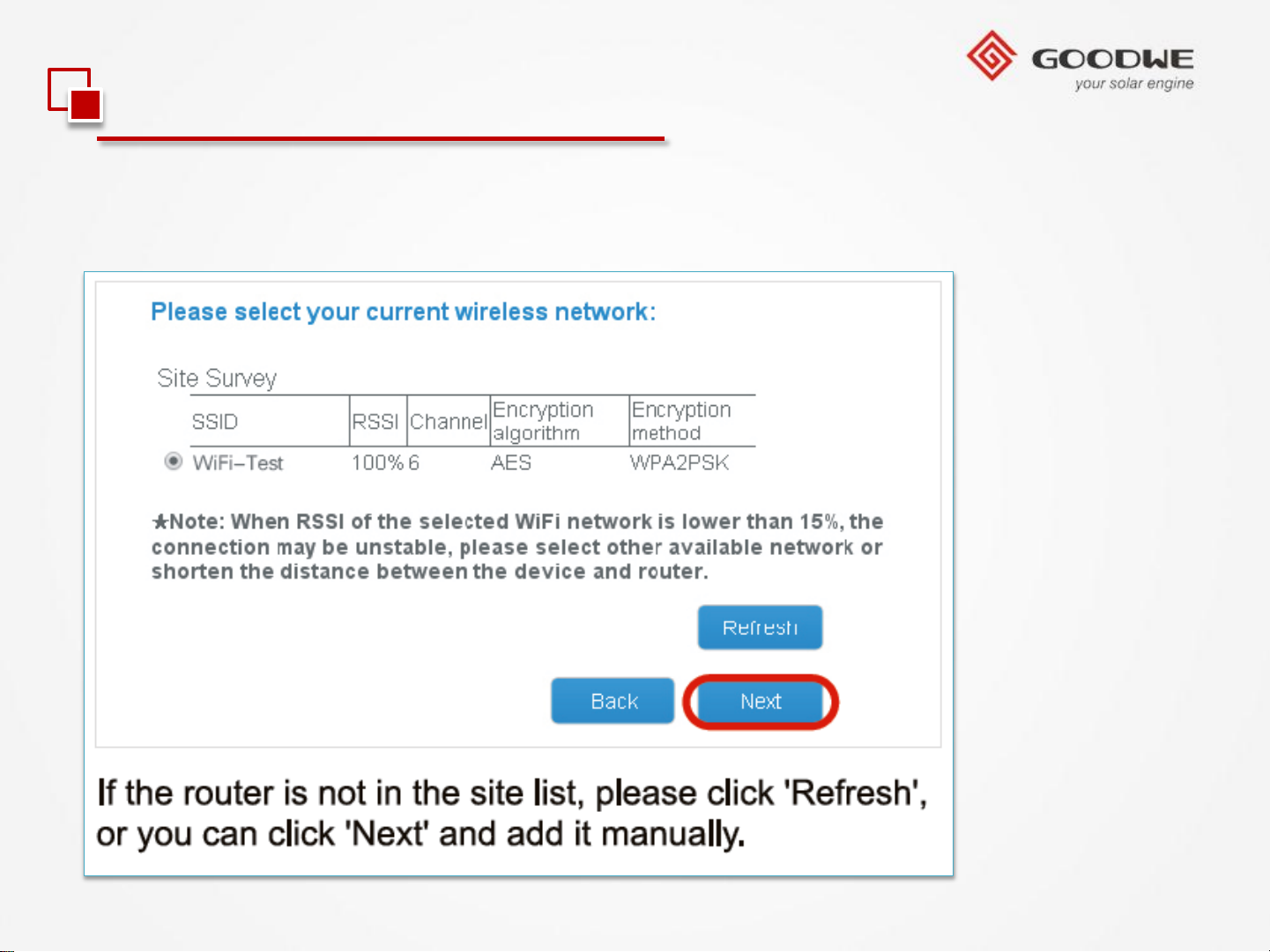
4). Select WiFi router’s SSID and click ‘Next’
© copy right reserved by GoodWe
Page 45
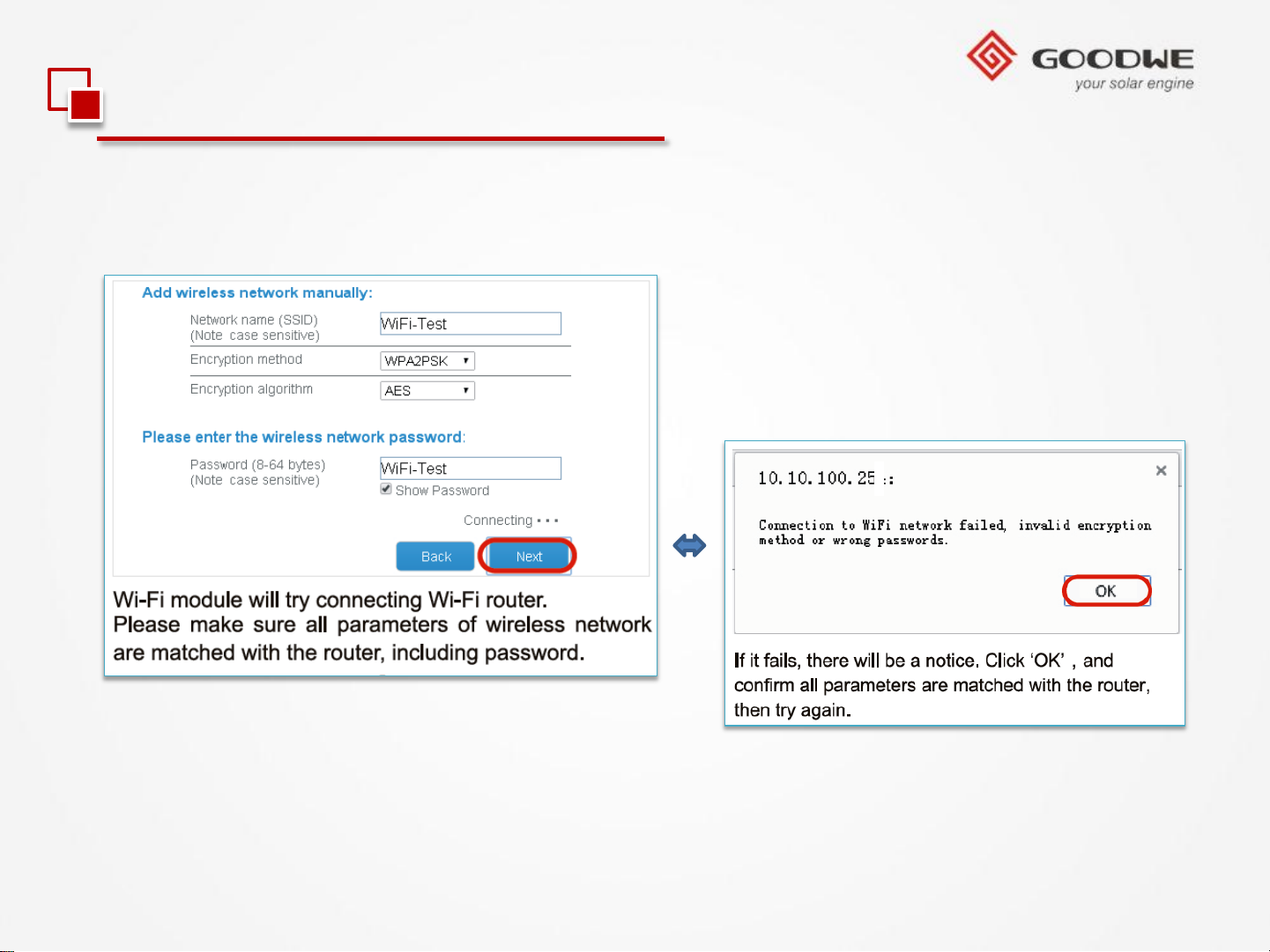
3.2 Monitoring Configuration
1.WiFi Inverter (Via laptop/Pad)
5). Type in password and click ‘Next’
© copy right reserved by GoodWe
3
Note: If it fails, there will be a
notice.
Page 46
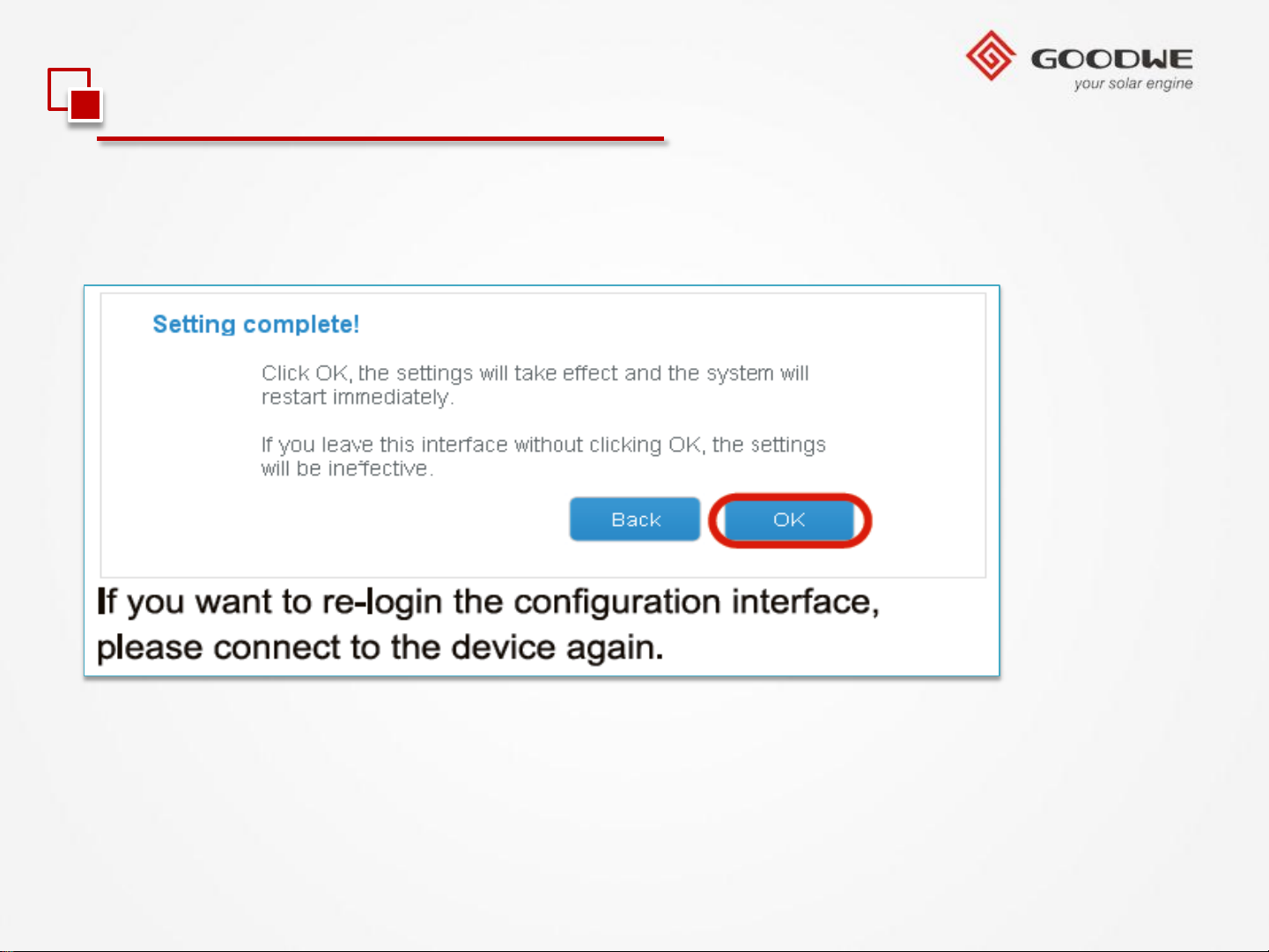
3.2 Monitoring Configuration
1.WiFi Inverter (Via laptop/Pad)
6). Click ‘OK’ and configuration process completes.
© copy right reserved by GoodWe
Page 47
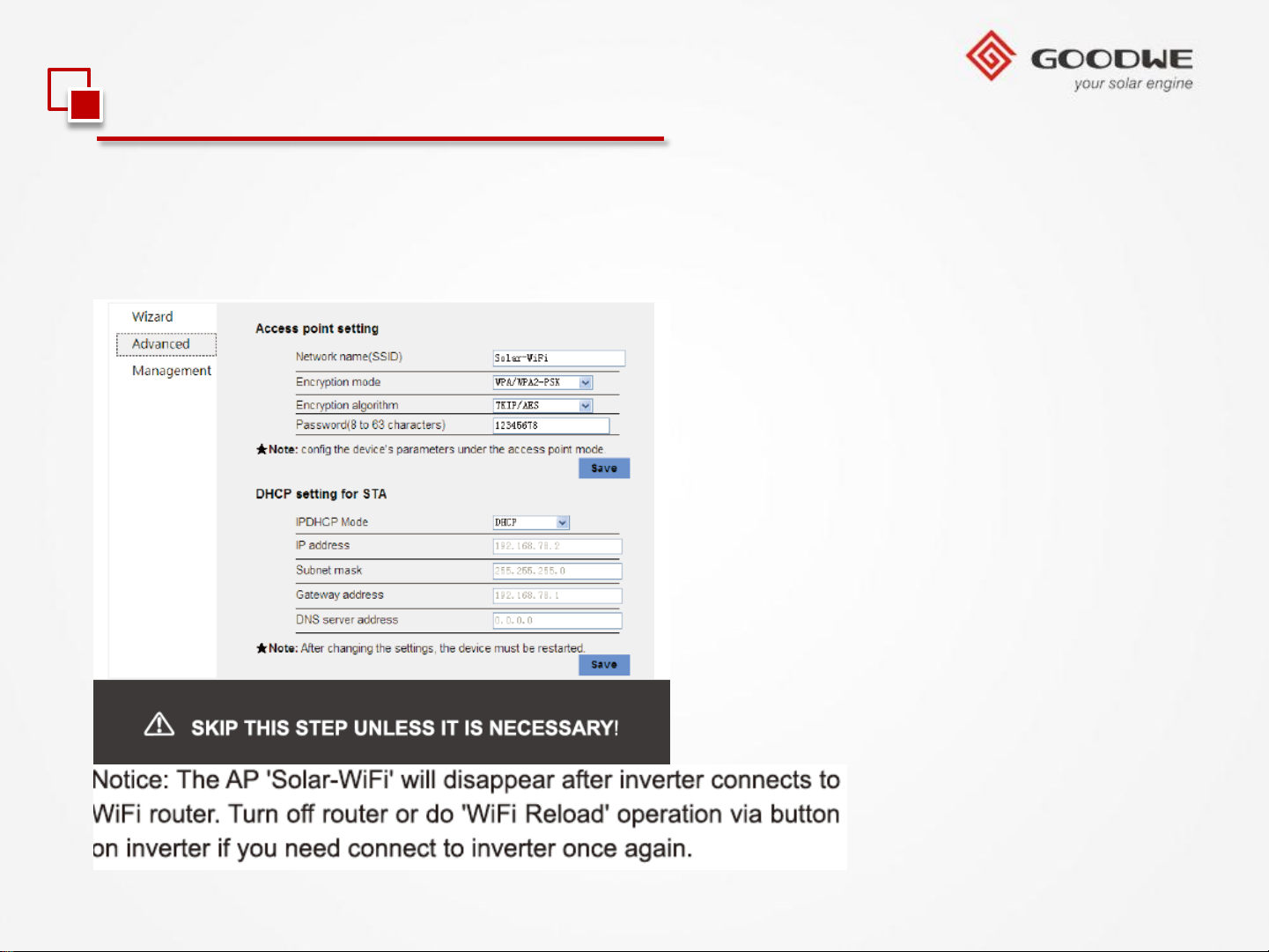
3.2 Monitoring Configuration
1.WiFi Inverter (Via laptop/Pad)
Note: If you want to modify the SSID and password of the inverter’s WiFi, please refer
to picture below.
© copy right reserved by GoodWe
Page 48
3.2 Monitoring Configuration
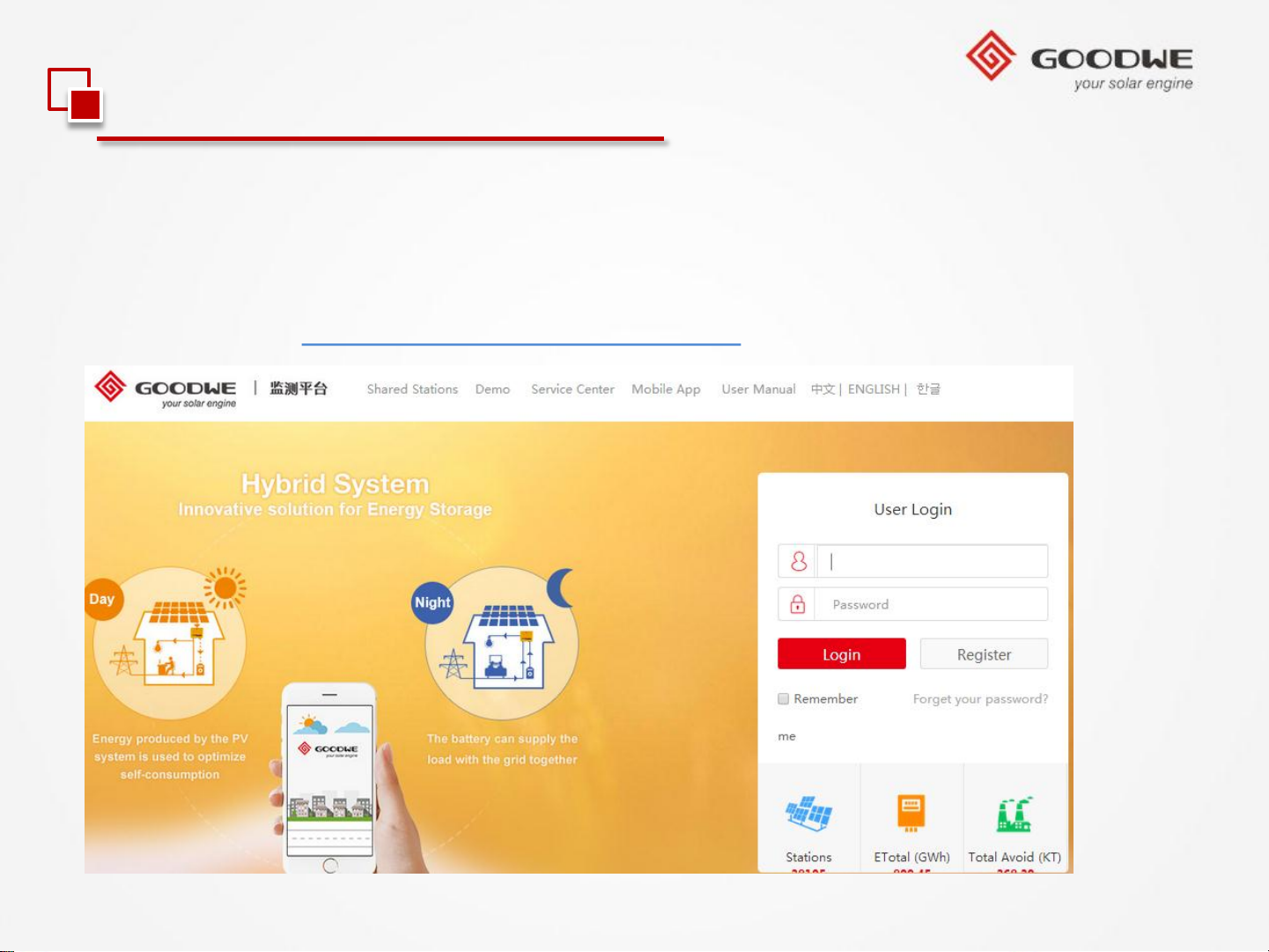
1.WiFi Inverter (Via laptop/Pad)
7). Disconnect the inverter WiFi , and connect to the local WiFi , create a station in
GoodWe portal with the SN and check code. System will be online in the portal.
Portal Website: www.goodwe-power.com.
© copy right reserved by GoodWe
Page 49

3.2 Monitoring Configuration
1.WiFi Inverter (Via APP)
1). Preparation
1.1). Power WiFi inverter (or EzLogger Pro WiFi) on.
1.2). If you are configuring WiFi inverter, make sure the yellow LED on front cover is
blinking. Otherwise please set the communication to WiFi according to user manual of
inverter at first.
1.3). Power WiFi router on.
1.4). Download latest version monitoring APP from google play store or Apple store
and install it on smart phone or pad.Run it.(APP’s name can be found in user manual)
© copy right reserved by GoodWe
Page 50
3.2 Monitoring Configuration
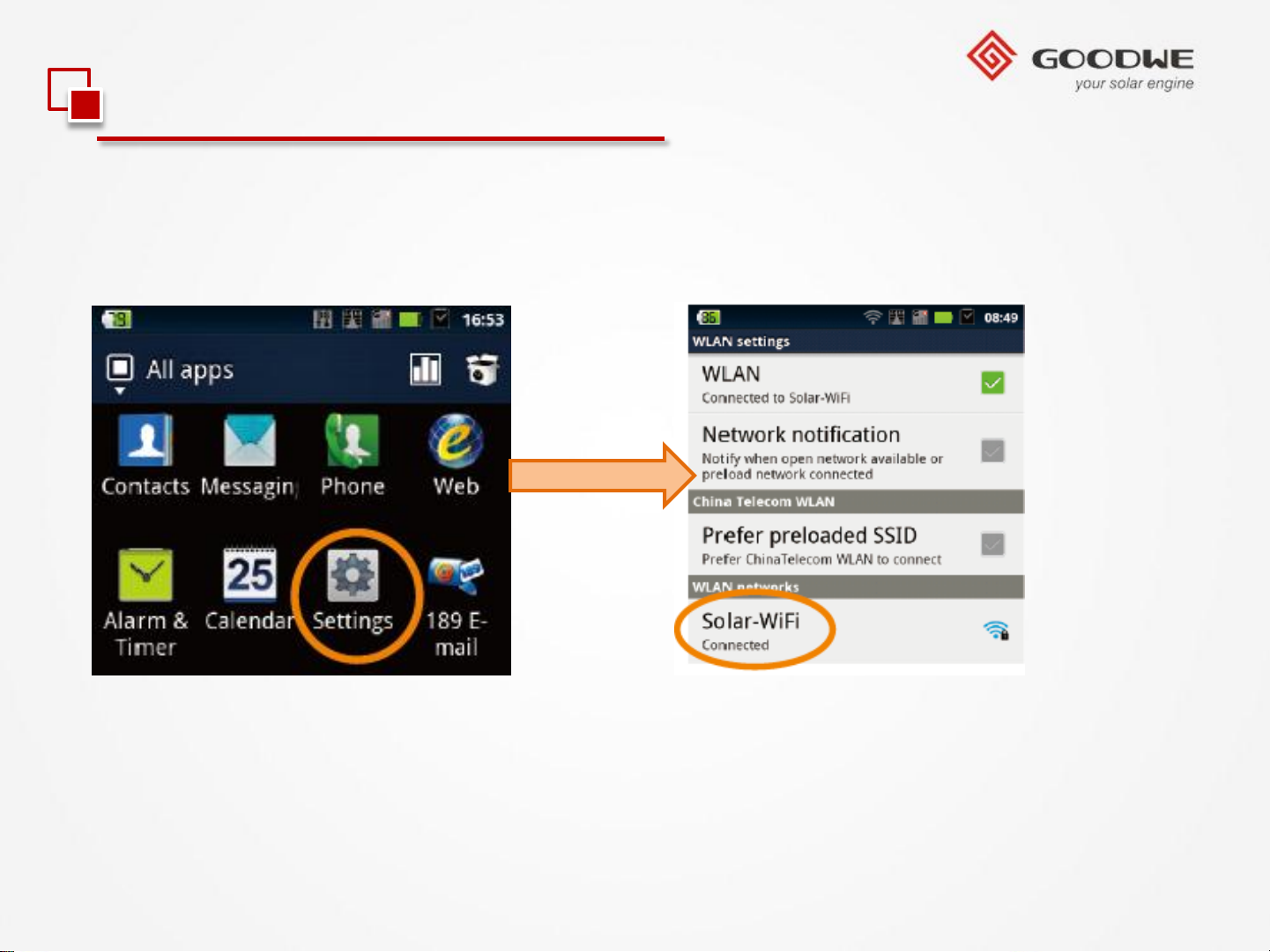
1.WiFi Inverter (Via APP)
2). Click “Settings” and connect to “Solar WiFi” . Password:12345678
© copy right reserved by GoodWe
Page 51
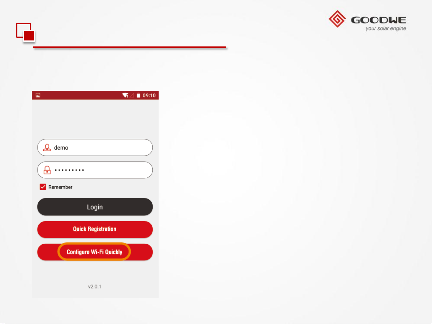
3.2 Monitoring Configuration
1.WiFi Inverter (Via APP)
3). Run App and press “Configure Wi-Fi Quickly”
© copy right reserved by GoodWe
Page 52
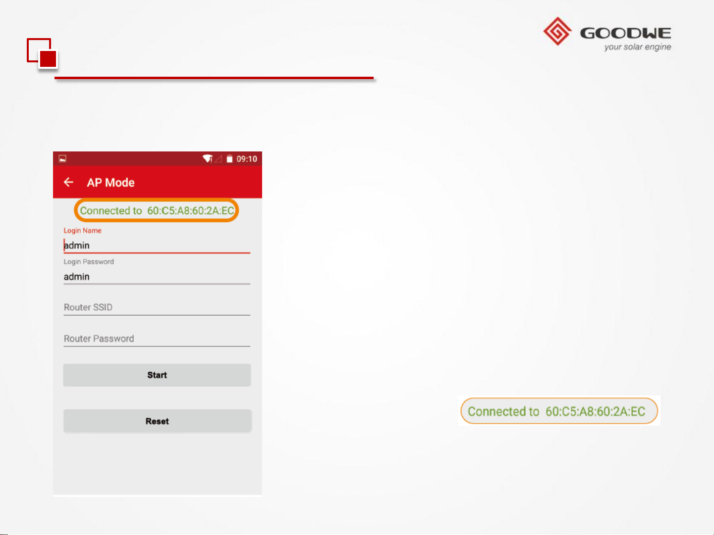
3.2 Monitoring Configuration
1.WiFi Inverter (Via APP)
4). The normal connection of Wi-Fi module
© copy right reserved by GoodWe
If it is not shown like this
Reconnect your smart device to Solar-WiFi again and
back to step 3.
Page 53
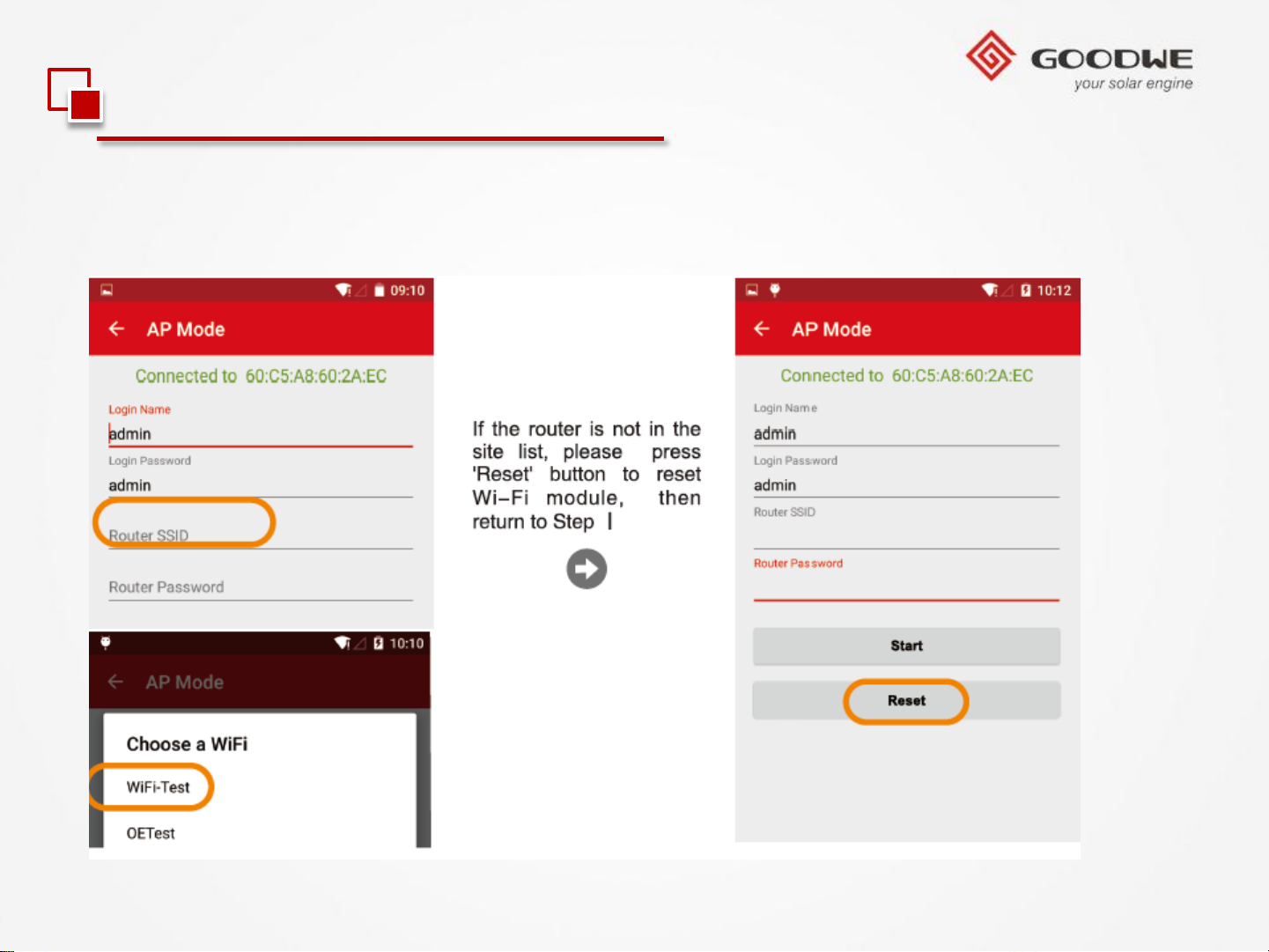
3.2 Monitoring Configuration
1.WiFi Inverter (Via APP)
5). Press “Router SSID” to choose your Wi-Fi router network.
© copy right reserved by GoodWe
Page 54
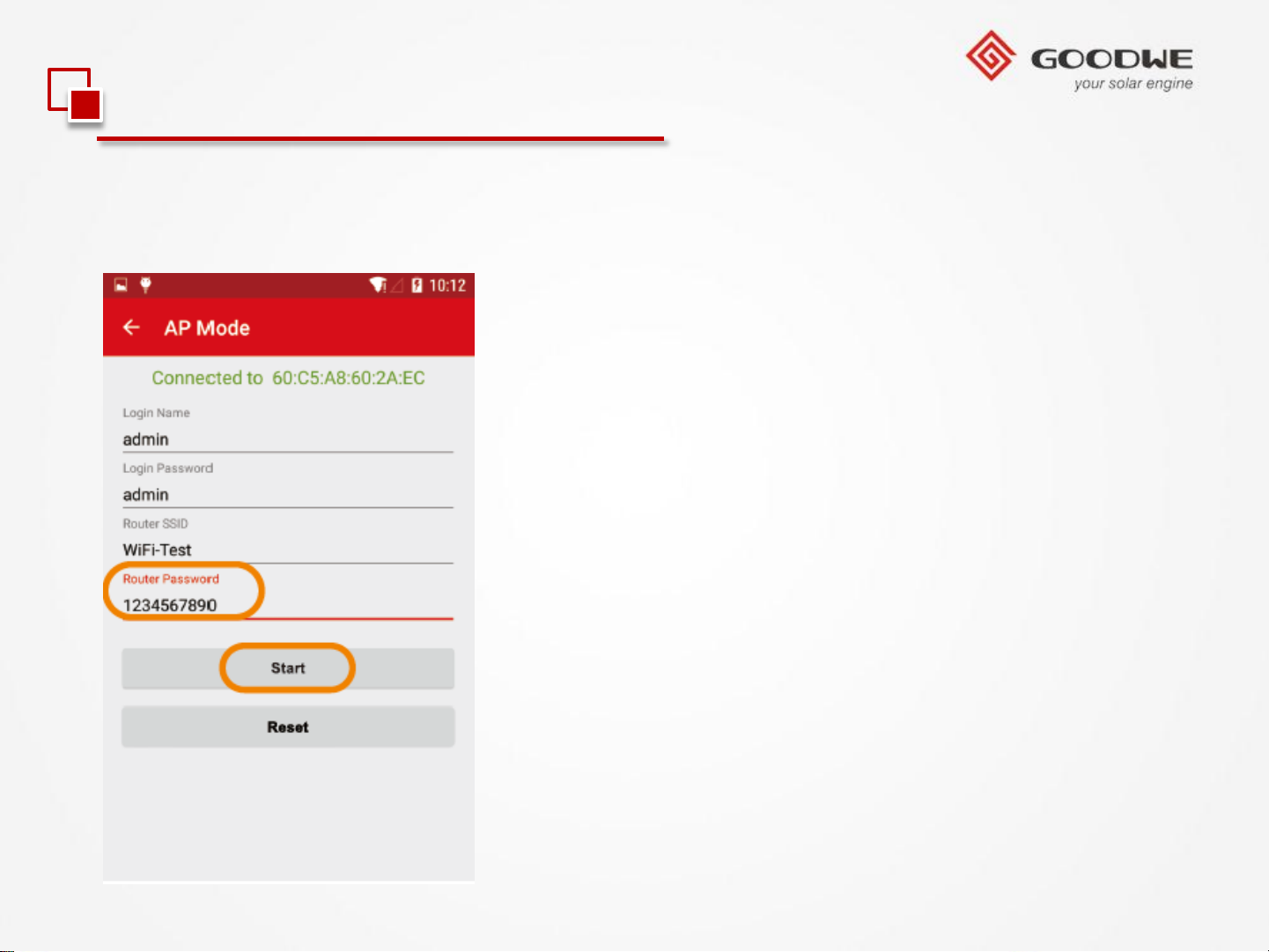
3.2 Monitoring Configuration
1.WiFi Inverter (Via APP)
6). Enter password then press “Start”.
© copy right reserved by GoodWe
Page 55
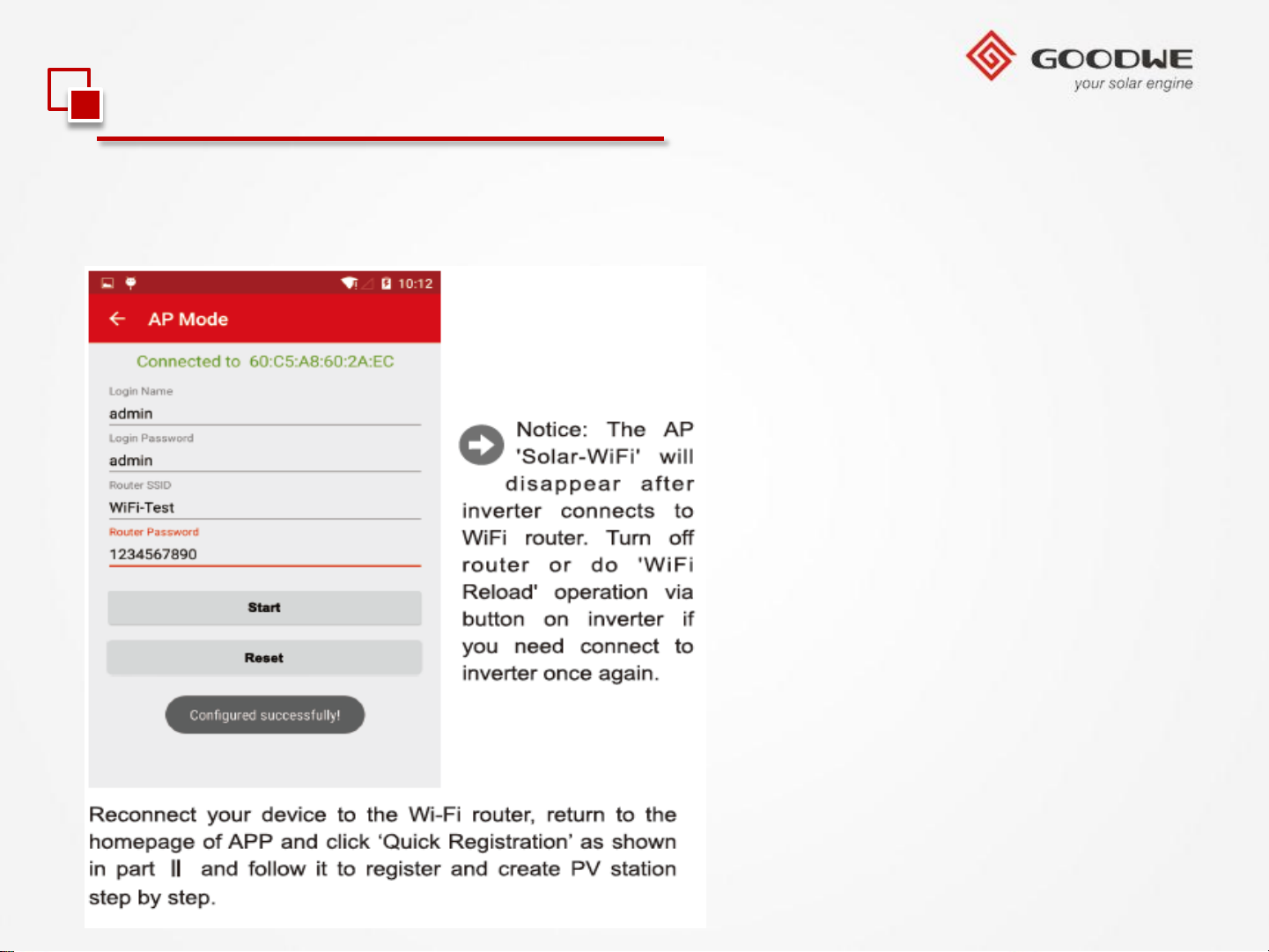
3.2 Monitoring Configuration
1.WiFi Inverter (Via APP)
7). Configured successfully
© copy right reserved by GoodWe
Page 56
3.2 Monitoring Configuration
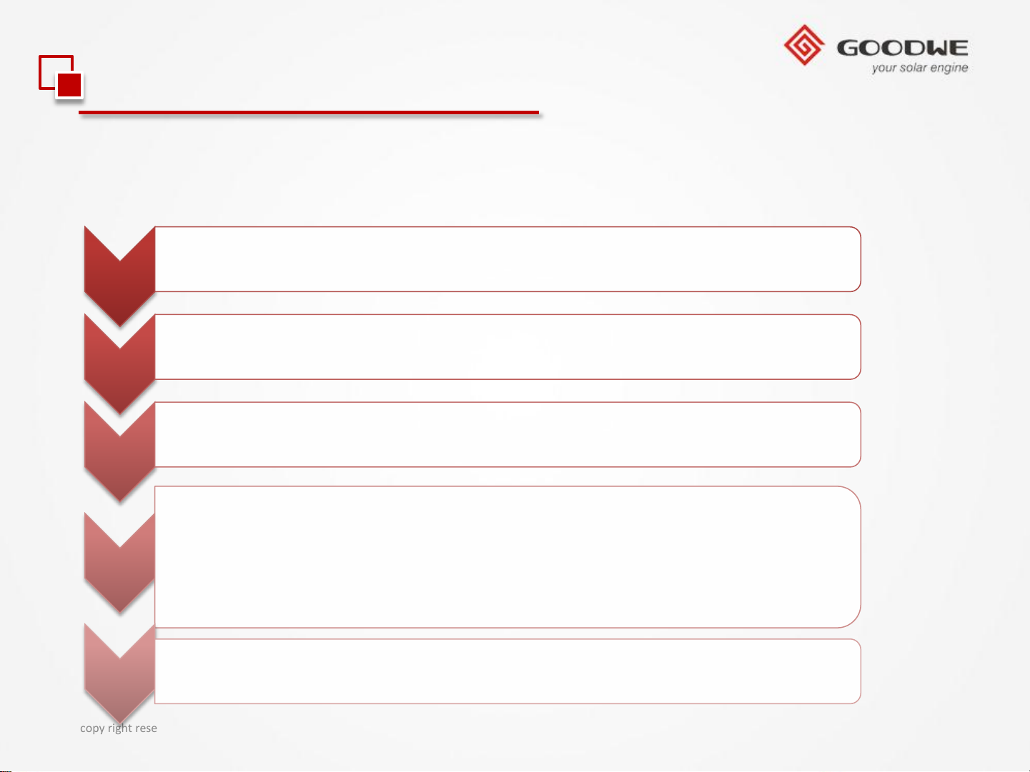
2.RS485 Inverter with EzLogger Pro
Please follow the steps below to configure the monitoring.
• Unpack the Ezlogger Pro , check if any missing accessary;
1
• Install the Ezlogger Pro to the target position;
2
• Connect the adapter;
3
• Device Connection;
4
5
© copy right reserved by GoodWe
• A: Connect the inverter to the Ezlogger Pro ;
• B: Connect the COM port to PC.
• Start to configure the Ezlogger Pro.
Page 57
3.2 Monitoring Configuration
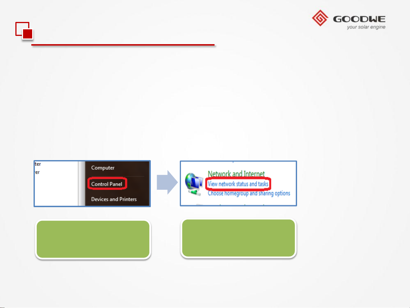
2.RS485 Inverter with EzLogger Pro
Please follow the steps below to configure the Ezlogger Pro to communicate the router
with fixed IP address.
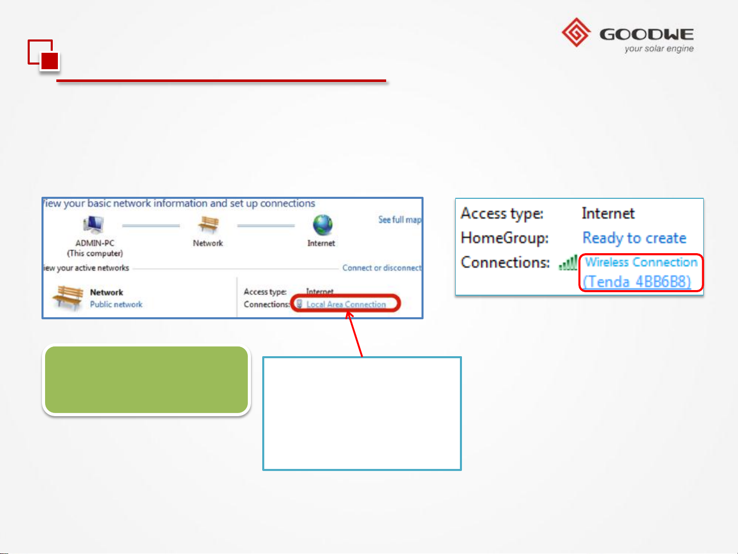
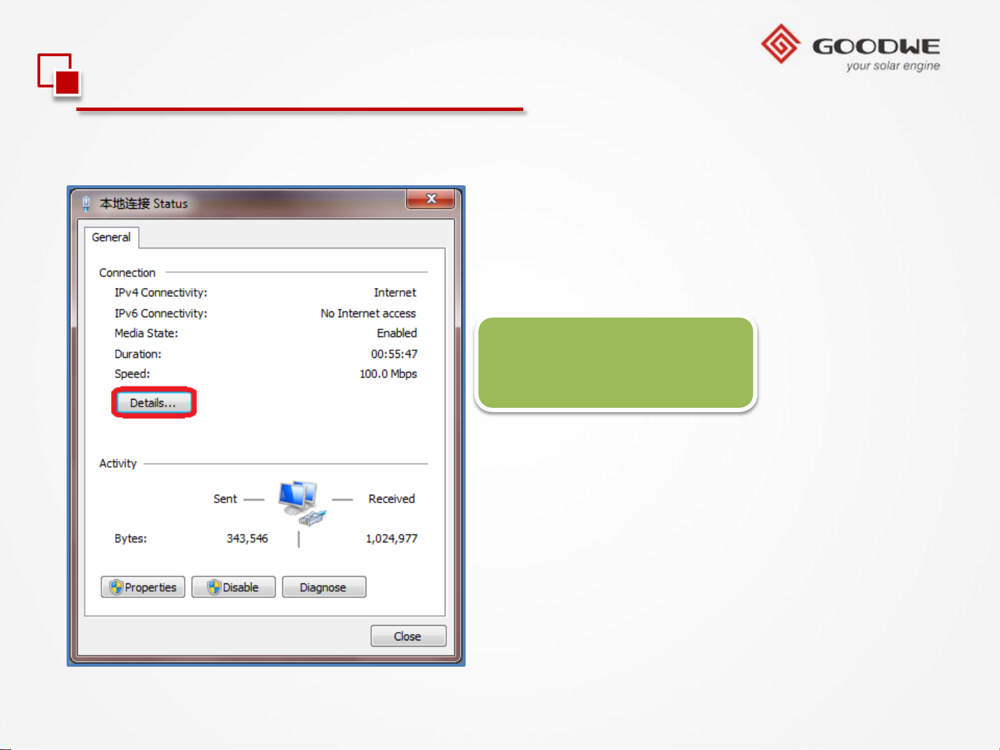
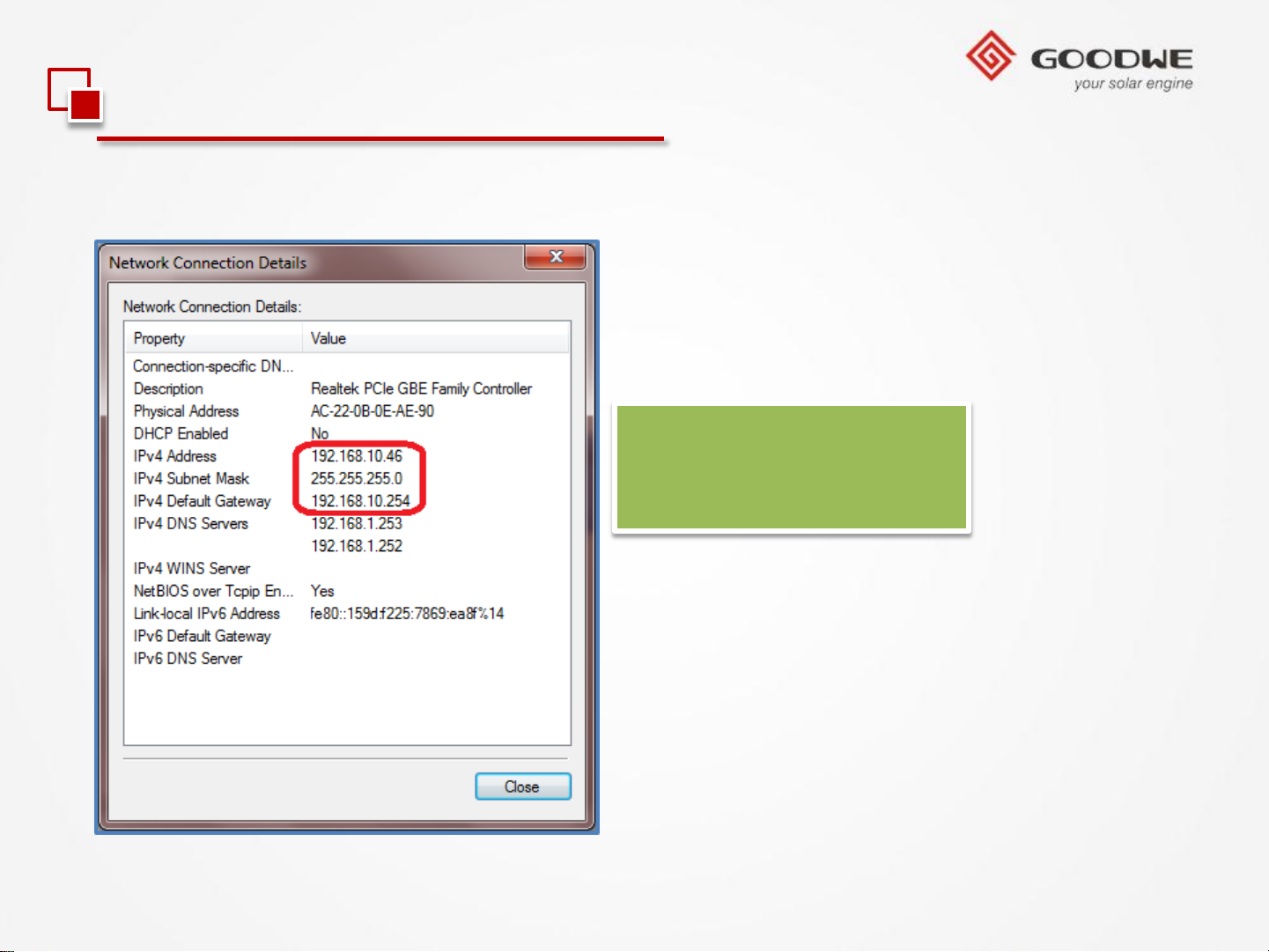
1). Check and record the IP Address, Subnet Mask, and Gateway after the laptop joins
the local area network;
Fig 1. Click ‘Start’, and
Click ‘Control Panel’.
© copy right reserved by GoodWe
Fig 2. Click ‘View
network status and tasks.’
Page 58
3.2 Monitoring Configuration
2.RS485 Inverter with EzLogger Pro
• Local Area Connection • Wireless Connection
Fig 3. Click ‘Local Area
Connection’.
© copy right reserved by GoodWe
Note: The “Local Area
Connection” option will
only appear when the
net port is connected.
Page 59
3.2 Monitoring Configuration
2.RS485 Inverter with EzLogger Pro
Fig 4. Click ‘Details’
© copy right reserved by GoodWe
Page 60
3.2 Monitoring Configuration
2.RS485 Inverter with EzLogger Pro
Fig 5. Record the 3 items
in Fig 5, which will be
useful later.
© copy right reserved by GoodWe
Page 61
3.2 Monitoring Configuration
2.RS485 Inverter with EzLogger Pro
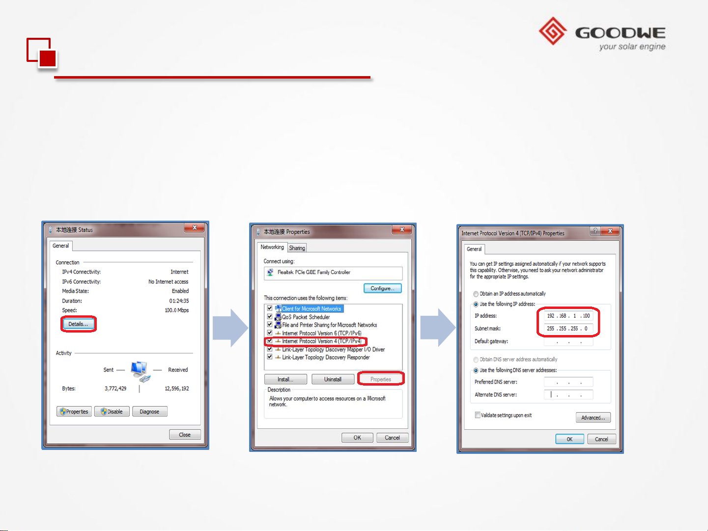
2). Connect the Ezlogger with laptop via STP cable;
3). Set the local area IP Address to 192.168.1.100 on the laptop;
© copy right reserved by GoodWe
Page 62
3.2 Monitoring Configuration
2.RS485 Inverter with EzLogger Pro
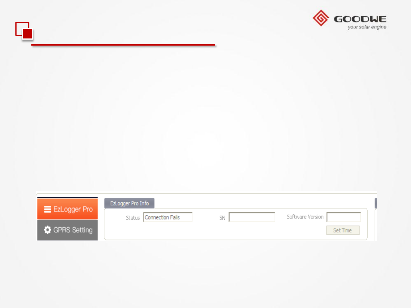
1、Run program ProMate on the laptop;
a).The program is in the USB disk in Ezlogger box.
b).If the USB disk is missing, please download ProMate from GoodWe website and
install the program on the laptop.
2、The connection status display as ‘Connection Succeeds’, and EzLogger Pro SN and
software version will come out soon;
© copy right reserved by GoodWe
Page 63
3.2 Monitoring Configuration
2.RS485 Inverter with EzLogger Pro
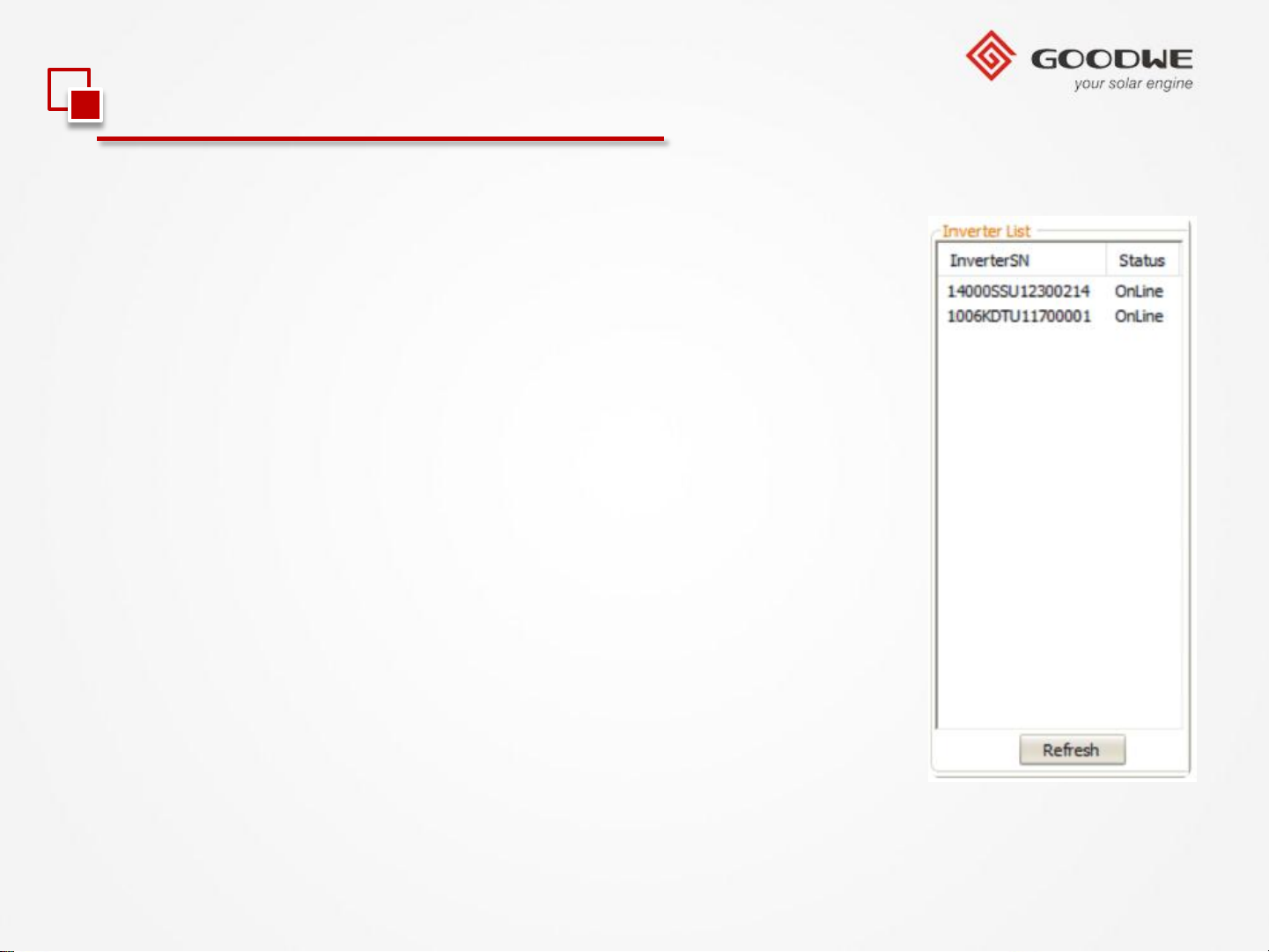
6). Click the refresh button, then all inverter’s SN will be listed;
If any inverter is missing, please check the cable connection off
the inverter.
© copy right reserved by GoodWe
Page 64
3.2 Monitoring Configuration
2.RS485 Inverter with EzLogger Pro
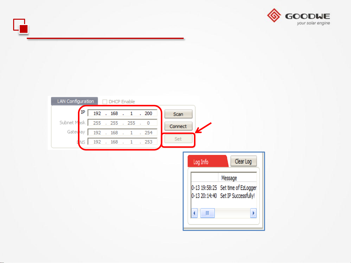
7、 Modify the IP Address, Subnet Mask, Gateway to
the one recorded (Refer to Page 12);
8、 Press ‘Set’, find ‘Set IP
Successfully!’ in ‘Log Info’;
© copy right reserved by GoodWe
Page 65
3.2 Monitoring Configuration
2.RS485 Inverter with EzLogger Pro
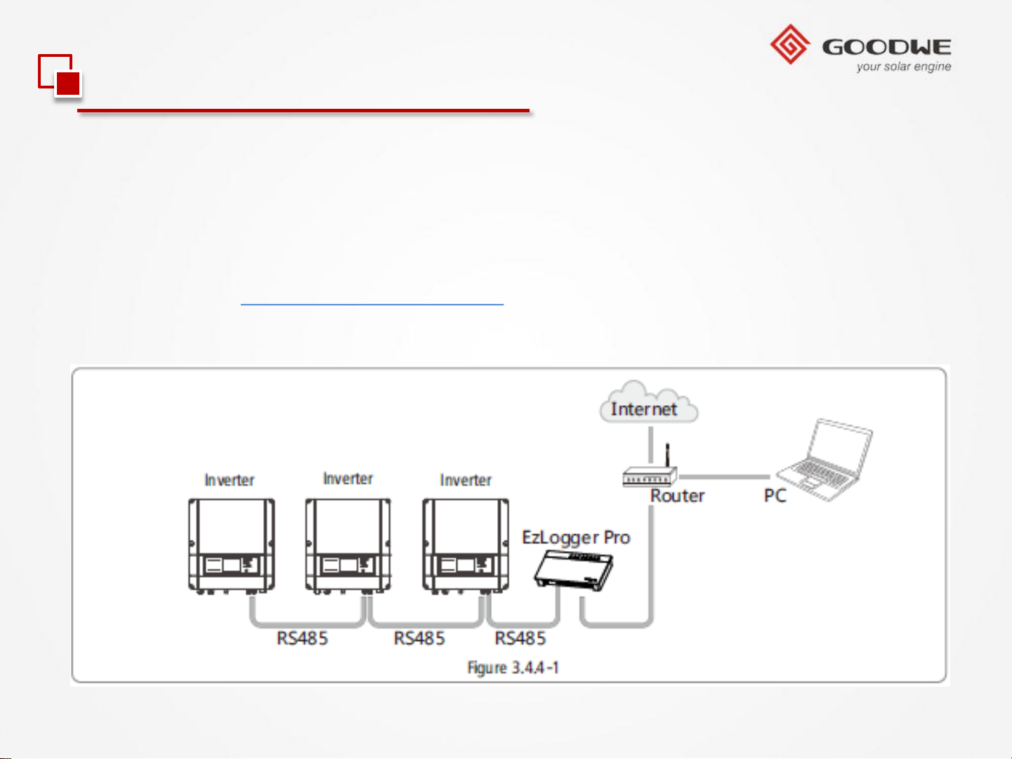
9). Then Disconnect the laptop, and connect the net port to the router, create a station
in GoodWe portal with the SN and check code. System will be online in the portal.
Portal Website: www.goodwe-power.com.
(Refer to picture as below)
© copy right reserved by GoodWe
Page 66

3.2 Monitoring Configuration
3.GPRS Inverter
GPRS inverter is unnecessary to configure for now , just to create a station in GoodWe
portal with the SN and check code. System will be online in the portal.
© copy right reserved by GoodWe
Page 67
Contents
Product Overview
Development Background
New Product Feature
Installation Guide
Internal Structure
Trouble Shooting
© copy right reserved by GoodWe
Technical Data
Monitoring Configuration
Certifications
Page 68
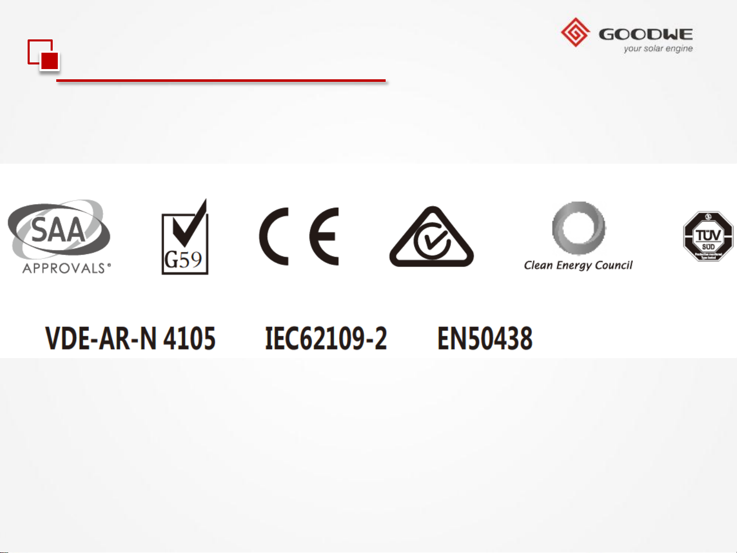
3.3 Certifications
MT series relevant certifications:
© copy right reserved by GoodWe
Page 69
© copy right reserved by GoodWe
THANKS
 Loading...