

Page 1
340 -0000 7-05
Official Website
Company Wechat
GoodWe(China)
No.189 Kunlunshan Rd.,SND,
Suzhou,215163,China
T: 400 998 1212
[email protected]
www.goodwe.com.cn
www.goodwe.com.cn
GoodWe(Australia)
www.goodwe.com.cn
GoodWe(Netherlands) GoodWe(UK)
www.goodwe.co.uk
Note: The information above is subject to change without prior notice,details refer to www.goodwe.com.cn.
SOLAR INVERTER
NS/DNS SERIES USER MANUAL
Page 2

1 Symbols
2 Safety
3 Installation
4 System Operation
5 Troubleshooting
6 Technical Parameters
7 Certificates
8 Maintenance
3.1 Mounting Instructions
3.2 Inverter Overview and Package
3.3 Inverter Installation
3.4 Electrical Connection
4.1 Indicator Lights
4.2 User Interface and Use of the Display
4.3 Error Code
4.4 WiFi Reset and Reload to Factory Setting
4.5 Special Adjustable Setpoints
............................................................................................................ 01
............................ 02
................ 02
.............................. 03
............................... 05
.................................... 13
......... 13
............................................... 16
......................... 17
........................................................................................................ 01
.................................................................... 17
.................................................... 18
.................................................................................. 22
.................... 17
.................................................................................. 22
Page 3
If th ere are m ore tha n 3 PV stri ngs on in put sid e, an addit ional f use ins talli ng will b e sugge sted.
An ea rthin g photo volta ic syst em need t o conne ct an Arc fau lt dete ctor on D C side.
The in verte r can exc lude th e possi bilit y of DC res idual c urren ts to 6mA i n the sys tem,W here an e xtern al RCD is r equir ed
in ad ditio n to the bu ilt-i n RCMU, typ e A RCD mu st be use d to avoi d tripp ing。
The PV- i s not gro unded a s defau lt conf igura tion.
CE Mark
Signals danger due to electrical shock and indicates the time (5minutes) to allow after the
inverter has been turned off and disconnected to ensure safety in any installation operation.
Caution! - Failure to observe a warning
indicated in this manual may result in minor
or moderate injury.
Danger of high voltage and electric shock!
Danger of hot surface!
Product should not be disposed as normal
household waste.
Components of the product can be recycled.
This side up - The package must always be
transported, handled and stored in such a
way that the arrows always point upwards.
No more than six (6) identical packages be
stacked on each other.
The package/product should be handled
carefully and never be tipped over or
slung.
Keep Dry – The package/product must be
protected from excessive humidity and
must accordingly be stored under cover.
1 Symbols
2 Safety
The NS /DNS se ries in verte r of Jian gsu Goo dWe Powe r Suppl y Techn ology C o, Ltd. (her einaf ter ref erred t o as Good We) str ictly
con forms t o relat ed safe ty rule s in desi gn and te st. Safe ty regu latio ns rele vant to th e locat ion sha ll be fol lowed d uring
ins talla tion,
com missi oning , ope ratio n and mai ntena nce. Impr oper op erati on may ha ve a risk o f elect ric sho ck or dam age to eq uipme nt
and p roper ty. (NS: Sin gle-M PPT,Sing le-Ph ase; DNS : Dual- MPPT,Sin gle-P hase)
Ins talla tion, ma inten ance an d conne ction o f inver ters mu st be per forme d by qual ified p erson nel, in co mplia nce wit h local
ele ctric al stan dards, re gulat ions an d the req uirem ents of l ocal po wer aut horit ies and /or com panie s.
To avoi d elect ric sho ck, DC inp ut and AC ou tput of t he inve rter mu st be dis conne cted an d wait at le ast 5 min utes be fore
per formi ng any in stall ation o r maint enanc e.
The te mpera ture of s ome par ts of the i nvert er may ex ceed 60℃ d uring o perat ion. To avoid b eing bu rnt, do no t touch t he
inv erter d uring o perat ion. Let i t cool be fore to uchin g it.
Keep c hildr en away f rom inv erter.
Do no t open th e front c over of t he inve rter. Apart f rom per formi ng work a t the wir ing ter minal ( as inst ructe d in this m anual ),
tou ching o r chang ing com ponen ts with out aut horiz ation m ay caus e injur y to peop le, damag e to inve rters a nd annu lment o f
the wa rrant y.
Sta tic ele ctric ity may d amage e lectr onic co mpone nts. Appro priat e metho d must be a dopte d to prev ent suc h damag e to the
inv erter ; oth erwis e the inv erter m ay be dam aged an d the warr anty an nulle d.
Ensu re the out put volta ge of the pr oposed PV a rray is lov er than th e maximu m rated inp ut volta ge of the inv erter; ot herwis e
the in verter m ay be damag ed and the wa rranty an nulled .
When e xposed t o sunligh t, the PV arr ay genera tes dang erous hi gh DC volta ge. Please o perate ac cordin g to our inst ructio ns,
or it wi ll result i n danger t o life.
PV mod ules sho uld have an I EC6173 0 class A rati ng.
If the e quipme nt is used in a ma nner not s pecifi ed by the man ufactu rer, the prote ction pr ovided by t he equip ment may be
impa ired.
Comp letely i solate t he equipm ent shou ld: switc h off the DC sw itch, disc onnect t he DC term inal, and di sconne ct the AC
term inal or AC brea ker.
Proh ibit ins erting o r pulling t he AC and DC term inals wh en the inve rter is el ectrif ied.
3 Installation
3.1 Mounting Instruction
In ord er to achie ve optim al perfor mance, the a mbient t empera ture shou ld be lowe r than 45℃.
For the c onvenie nce of che cking th e LCD displ ay and poss ible mai ntenan ce activ ities, ple ase insta ll the inv erter at ey e level.
Inve rters sh ould NOT be in stalle d near infl ammabl e and explo sive ite ms. Any st rong elec tro-ma gnetic e quipme nt shoul d be
kept awa y from ins tallat ion site.
Prod uct labe l and warni ng symbol s hall be cl ear to read a fter inst allati on.
Plea se insta ll invert er in the pl ace where i s not expos ed to dire ct sunli ght, rain an d snow.
3.2 Inverter Overview and Package
Che ck the sc ope of de liver y for com plete ness an d any vis ible da mage.
3.2.1 Inverter Overview
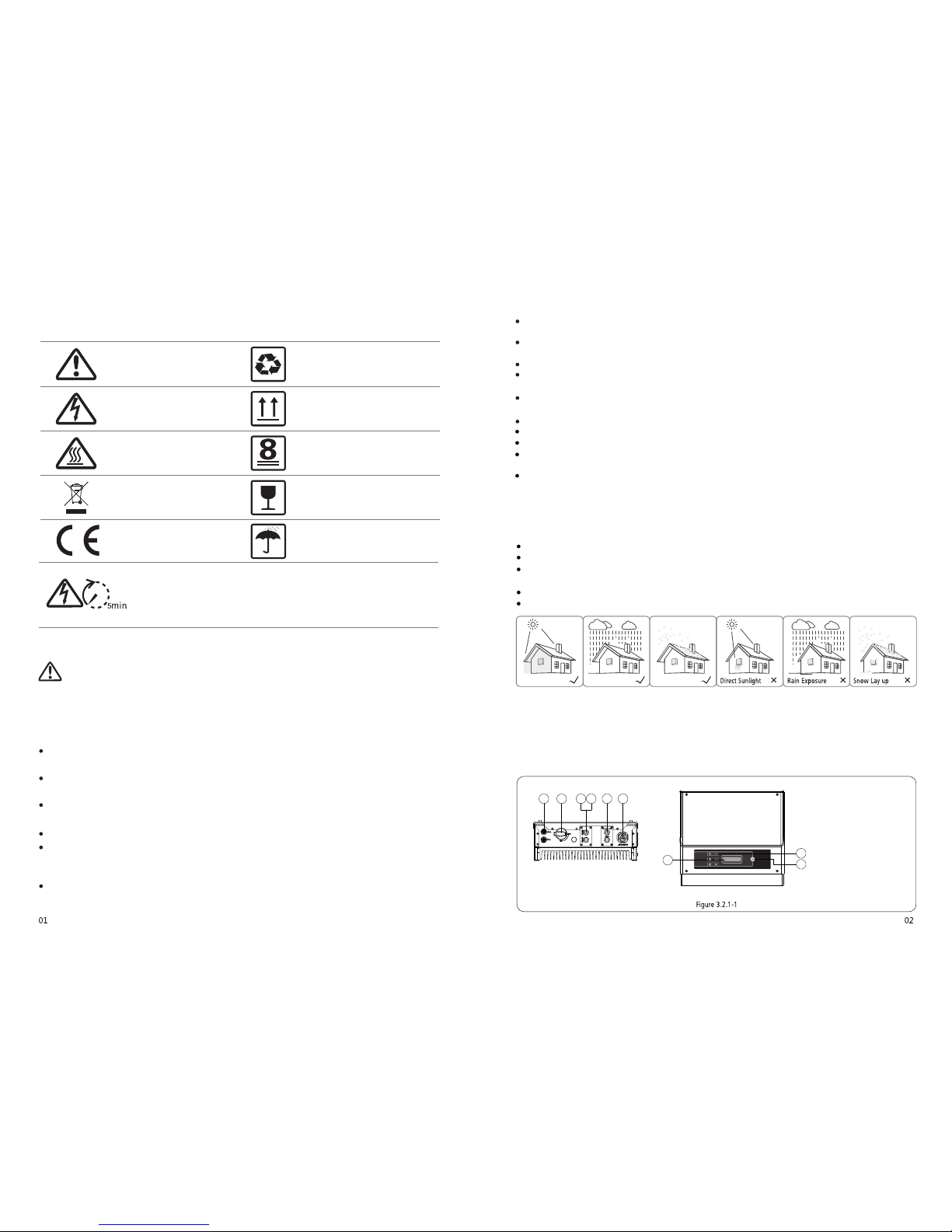
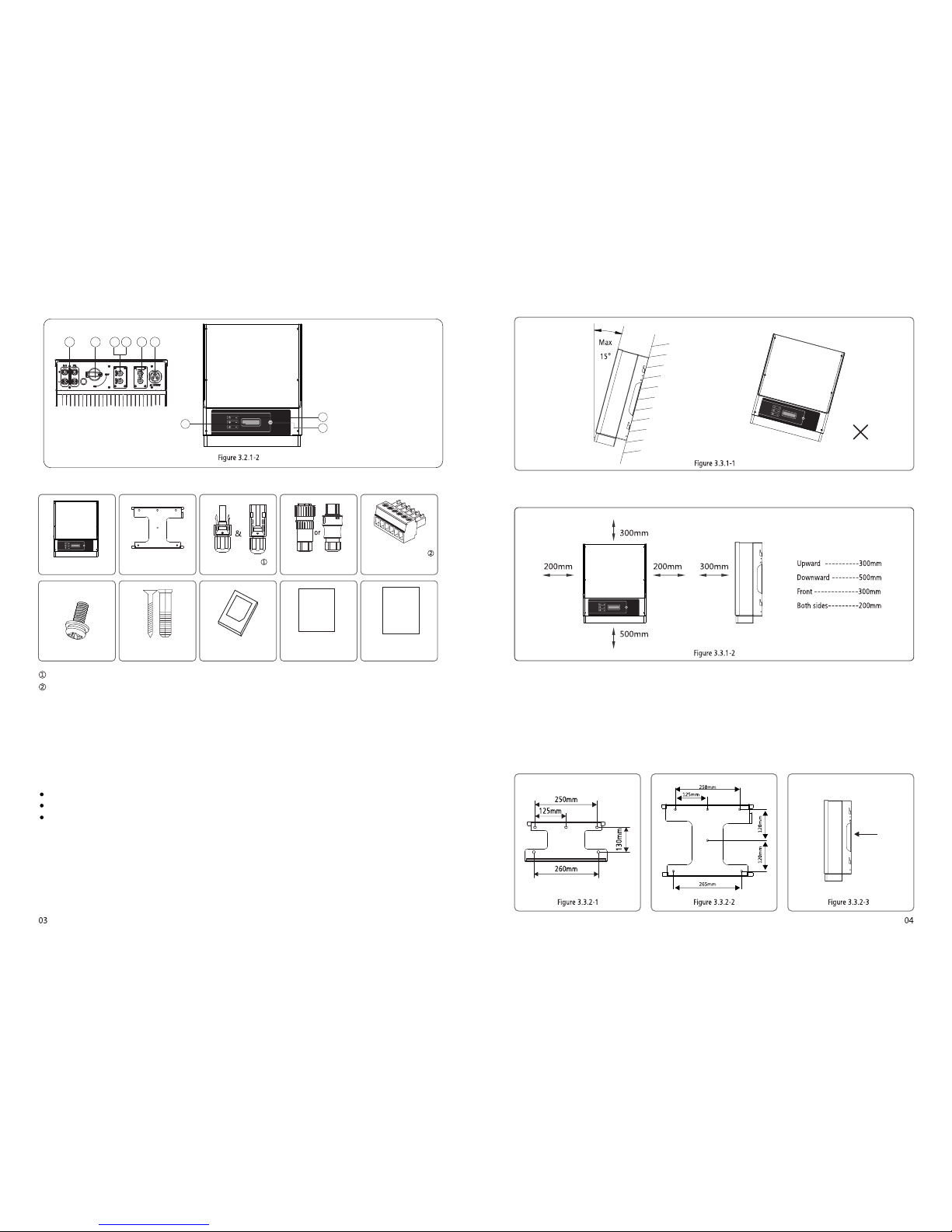
Appearance of NS Series 1-3KW refer to Figure3.2.1-1. Appearance of NS Series 3.6-5KW and DNS Series 3-5KW refer to Figure3.2.1-2.
213 4 5 6
7
8
9
1. PV input terminals
2. DC Switch (Optional)
3. RS485 port or USB port
4. WiFi BOX (Optional)
S. CT and DRED function
(Optional)
6. AC output terminal
7. LCD display
8. Indicator lights
9. Button
Page 4
.....
..
.
...
.
.
.......
..
.
.
..
.
..
...
213 4 5 6
7
8
9
1. PV input terminals
2. DC Switch (Optional)
3. RS-485 port or USB port
4. Wi-Fi antenna port (Optional)
5. CT and DRED function
(Optional)
6. AC output terminal
7. LCD display
8. Indicator lights
9. Button
3.2.2 Package
6Pin Terminalx1
2Pin Terminalx1
AC Plu gX1
DC PlugX2pair
Wall-mounted
Bracket x1
Inverterx1
Screwx4
Expansion Bolt sx5 Expansion Bolt sx5
Wi-Fi
Connection
Guide
Quick
Installati on
Guide
Quick Installa tion
Guidex1
Wi-Fi Connection
Guidex1
(WiFi BOM only)
There is 1 pair of DC connec tors in NS Series 1-3KW. and 2 pairs of DC conn ectors in NS Series 3.6-5 KW and DNS Series 3-5KW;
6Pin termi nal for RS485 functio n, 2Pin termi nal for CT function.
3.3 Inverter Installation
3.3.1 Selecting the installation location
The fol lowing m ust be cons idered w hen sele cting the b est loca tion for an i nverte r:
The mount a nd insta llatio n method mu st be appr opriat e for the inv erter' s weight an d dimens ions.
The locat ion must b e well vent ilated a nd shelt ered from d irect su nlight .
The inver ter must b e install ed verti cal or wit h a backwar d tilt less t han 15. No sid eways til t is allow ed. The connec tion
area m ust point d ownwar ds. Refer to Fig ure 3.3. 1-1.
To allow dissipat ion of heat, and for convenie nce of dismantling , clearanc es around the inverte r must be at least:
The installa tion position sha ll not prevent access to the di sconnection mea ns.
3.3.2 Mounting Procedure
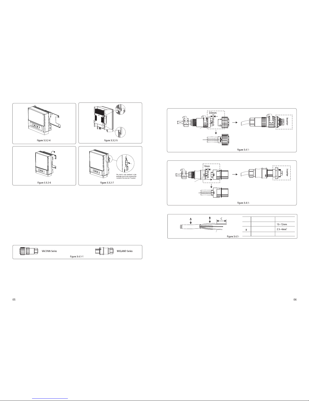
(
refe rred to Figu re 3.3.2 -1, NS 3.6k W-5kW & DNS 3k W-5kW ref erred to Fi gure 3.3 .2-2.
(2) Fix t he wall mou nting bra cket on the wa ll using t he expans ion bolt s in the acce ssorie s bag.
(3) Ho ld the inve rter by th e side groo ve as Figur e 3.3.2-3 .
(4) In stall th e inverte r on the wall -mount ed bracke t. NS 1 kW~3kW r eferre d to Figure 3. 3.2-4, 3. 3.2-5. NS 3. 6kW-5kW & D NS
3kW-5 kW refer red to Figu re 3.3.2- 6, Figure 3. 3.2-7.
1) Use t he wall-m ounted b racket as a te mplate a nd drill ho les in the wa ll,10 mm in d iamete r and 80 mm dee p. NS 1 kW~ 3kW
Page 5
2
2
3
4
*Ne utral c onduc tor sha ll be blu e, line con ducto r shall b e black o r brown ( prefe rred) , protec tive ea rth bon ding li ne shal l be
yel low-g reen.
*Fix ( momen t: 0.6N.m ) the con necto r of AC cabl e to the co rresp ondin g termi nals
3.4.1 Connection to grid (AC side Connection)
3.4 Electrical Connection
(1) Ch eck the gri d voltag e and freq uency if it c an comply w ith the re quired vo ltage an d freque ncy of inve rter con nectio n.
(2) Add br eaker or fu se to AC side, the sp ecific ation sho uld be mor e than 1.25 t imes of ra ted AC output c urrent .
(3) The PE li ne of inve rter shou ld be conn ected to th e earth, ma ke sure the im pedanc e of neutra l wire and e arth wire l ess than
10 ohm .
(4) Di sconne ct the brea ker or fuse b etween th e invert er and the ut ility.
(S) Co nnect th e inverte r to the gri d as follow s:
There a re two AC conne ctor bra nds for inv erter, VACONN an d WIELA ND. Please re fer to Figu re 3.4.1 -1
(6)Th e AC line c onstru ction sh all be such t hat if the co rd shoul d slip in its a nchora ge, placin g a strain on c onducto rs, the
prot ective e arthin g conduct or will be t he last to ta ke the strai n. such as th e PE line is lo ngger tha n L and N.
Ins talla tion in struc tion of VACO NN seri es plea se refe r to Figur e 3.4.1 -2.
fast en scre w cap clo ckwis e
4mm Copper Conductor
Material (Annealed cop per wire)
2
fast en scre w cap clo ckwis e
fast en scre w cap clo ckwis e
Fast ening t hree sc rews
to en sure ea ch scre w head
is no t excee ding th e surfa ce
Fast ening t hree sc rews
to en sure ea ch scre w head
is no t excee ding th e surfa ce
Material (Anneal ed copper wire)
Ins talla tion in struc tion of WI ELAND s eries p lease re fer to Fi gure 3. 4.1-3 .
Cable speci fication of AC side please refer to Figure 3.4.1 -4.
Annealed copper wir e
Conductor Material
Sectional Area
O.D.A
Bare Wire Length
C
Grade Description
Value
10mm around
Page 6
The inverter can exclude the poss ibility of DC residual currents to 6mA in the system,W here an external RCD is required in addition
to the built-in RCMU, type A can be used, type B or type A must be used to avoid tripping。
(6) Po sitiv e shall b e red, neg ative s hall be b lack .
(7) The m inimu m insul ation r esist ance to g round o f the PV pa nels fo r NS seri es must e xceed 1 6.7kΩ (R = 50 0/30 mA ) th e
min imum in sulat ion res istan ce to gro und of th e PV pane ls for DN S serie s must ex ceed 19 .3kΩ( R = 580/3 0 mA),t here is a
ris k of shoc k hazar d if the re quire ment of m inimu m resis tance i s not met .
,
3.4.2 AC circuit breaker and leakage current protection device
In order to ensure that the inverte r can be safe and reliable to discon nect from the power grid, please install an
independe nt two pole circuit breaker to protect the inverter.
Inv erter m odel
GW1 000-N S/GW1 500-N S/GW2 000-N S/GW2 500-N S
GW3 000-N S/GW3 000D- NS/GW 3600- NS/GW 3600D -NS
GW4 200-N S/GW4 200D- NS/GW 5000- NS/GW 5000D -NS
Recommen ded circuit breaker specif ications
Note: Multiple inver ters are not allowed to share a circuit breaker.
The integrated leaka ge current detection device of the inverte r can detect extern al leakage current in real time. When the
detected leak age current exceeds the limit value, inverter will quick ly disconnect with the grid, If the leakage current
protectio n device is installe d externally, the action current should be 300mA or higher.
3.4.3 DC Side Connection
(
per manen tly dam age the u nit.
(2) The open c ircui t volta ge of the P V strin gs cann ot exce ed the ma ximum i nput vo ltage o f the inv erter.
(3) Only DC c onnec tors pr ovide d by us are p ermit ted to us e.
(4) The posi tive an d negat ive pol e is forb id to con nect PE w ire (Gr ound wi re), oth erwis e, it will da mage th e unit.
(5) Don't c onnec t posit ive or ne gativ e pole of P V strin g to PE wir e. Oth erwis e, it will ca use dam age to in verte r.
1)B efore c onnec ting th e PV stri ngs, plea se ensu re the pl ug conn ector s have th e corre ct pola rity. Inc orrec t polar ity cou ld
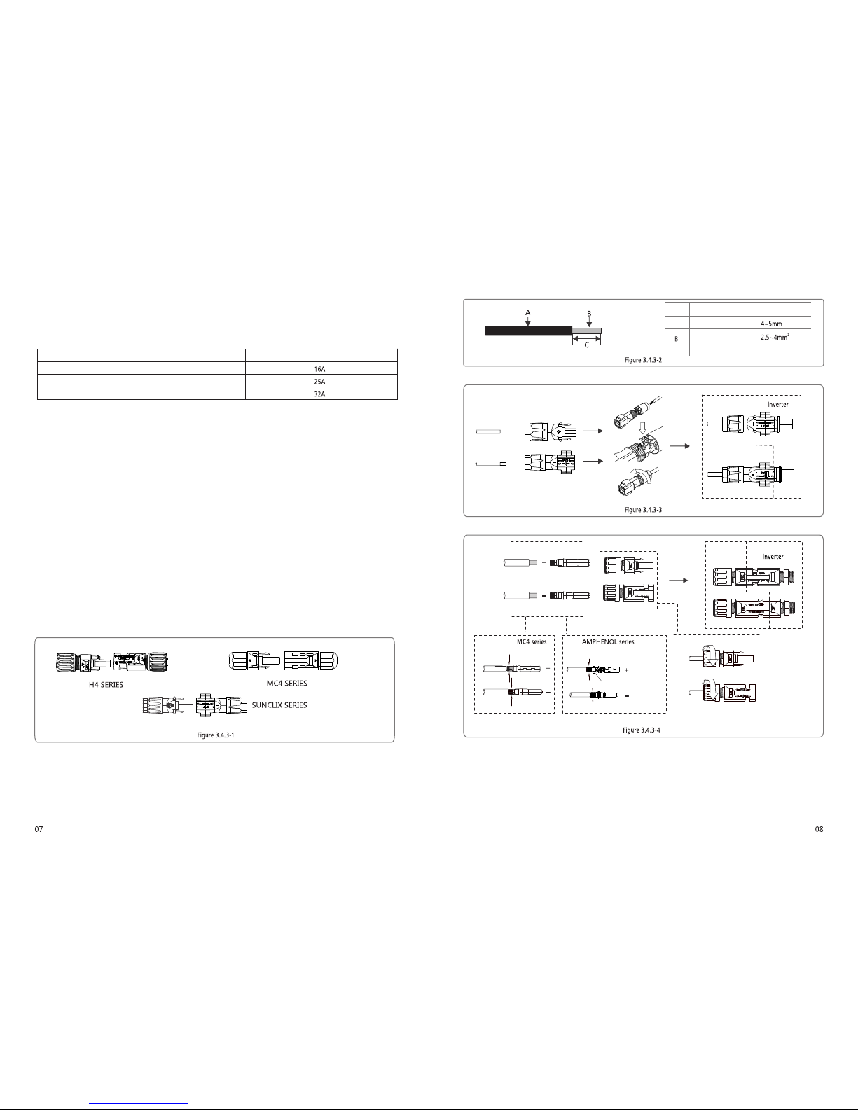
There are thre e types of DC connector s, SUNCLIX / MC4 an d AMPHENDL H4 se ries. Please refer to Figure 3. 4.3-1.
DC Cable specifica tion is showed as Figure 3.4.2-2.
Conductor Material
Sectional Area
O.D.A
Bare Wire Length
C
Grade Description
Value
7mm around
DC Cab le shou ld be use d edica ted PV ca ble
(Sug gest us ing 4mm P V1-F wi re)
2
Installat ion instruction of SUNCLIX please ref er to Figure 3.4.3-3.
Installat ion instruction of MC4 and H4 Series please refer to Figure 3.4.3 -4.
Negative conn ector
Positive connect or
Negative conn ector
Positive connect or
Limit buckle can't
crimping the wire
Special tools are used to stit ching
Page 7
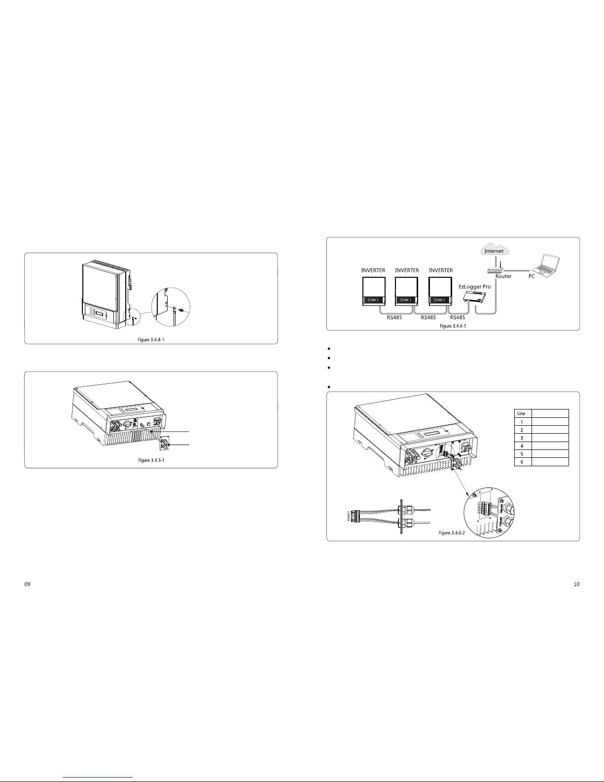
3.4.4 Earth Terminal Connection
The inverter is added ear th terminal according to the requ irement of EN 50178. It is must that installati on person should connect the
terminal to eart hing wire.
Position of earth term inal as Figure 3.4.3-1.
The earth connecti ng terminal is on the side of inverter, illustrated as Figure 3.4 .4-1. The customer should sel ect to grounding base on
site conditi on.
3.4.5 USB Communication
USB cabl e should be connec ted as Figure 3.4.5 -1.
2.Ins ert the USB data cabl e
1.Rem ove RS485 waterp roof assembl y
USB inte rface just for aft er-sales servi ce team repair in vter, shall not us e the it for any other pur poses.
3.4.6 RS485 Communication
This function is only app lied to inverters with RS485.
The RS485 interfac e is used to connect EzLo gger Pro and the maximum total lengt h of all connectin g cables should not exceed 800m.
RS485 connec tion is referred to 3.4.6-1.
(1)C onnect ion Proc edure:
Put th e cable thr ough the c ompone nts in this o rder: scre w cap, one-h ole seal ing ring, in sulati on body an d sheet met al parts.
Take the gree n termin al out of acc essory b ag. cable sh ould be co nnecte d as Figure 3. 4.6-2.
Inse rt the gree n termin al into th e corresp onding i nterio r termina l of the inv erter. Pull ca ble soft ly to maint ain the cab le not
to be pu lled out.
Lock t he sheet me tal part s onto the bo x and tight en the scr ew cap.
(2)Co nnect the inver ter to EzLogger Pr o with RS485 cable, and Ez Logger Pro to netw ork switch or rou ter with CATSE STP cab le.
Fun ction
RS4 85+
RS4 85-
Res erved
Res erved
RS4 85+
RS4 85-
Page 8
2
1
/
The in verte r compl ies wit h IEC62 109-2 c hapte r 13.9. Whe n earth f ault oc curs,t he faul t indic ator LE D on fron t cover w ill
lig ht up, and, fo r wifi in verte r, it wil l email t he faul t infor matio n to cust omer, for n on wifi i nvert er ,the b uzzer i n inver ter
wil l keep rin ging 1 mi nute an d ring ag ain aft er half a n hour un less th e fault i s resol ved(Th is func tion is o nly ava ilabl e to
Aus trali a/ New Ze aland ).
3.4.7 Wi-Fi Communication
The Wi-Fi communication fun ction is only applied to WiFi BOX, the detailed configura tion instruction can be refer red to Wi-Fi
Configur ation in the accessory box.
After config uration, please browse http ://www.goodwe-powe r.com to create PV station.
3.4.8 Power Limiting Device & DRED Installation
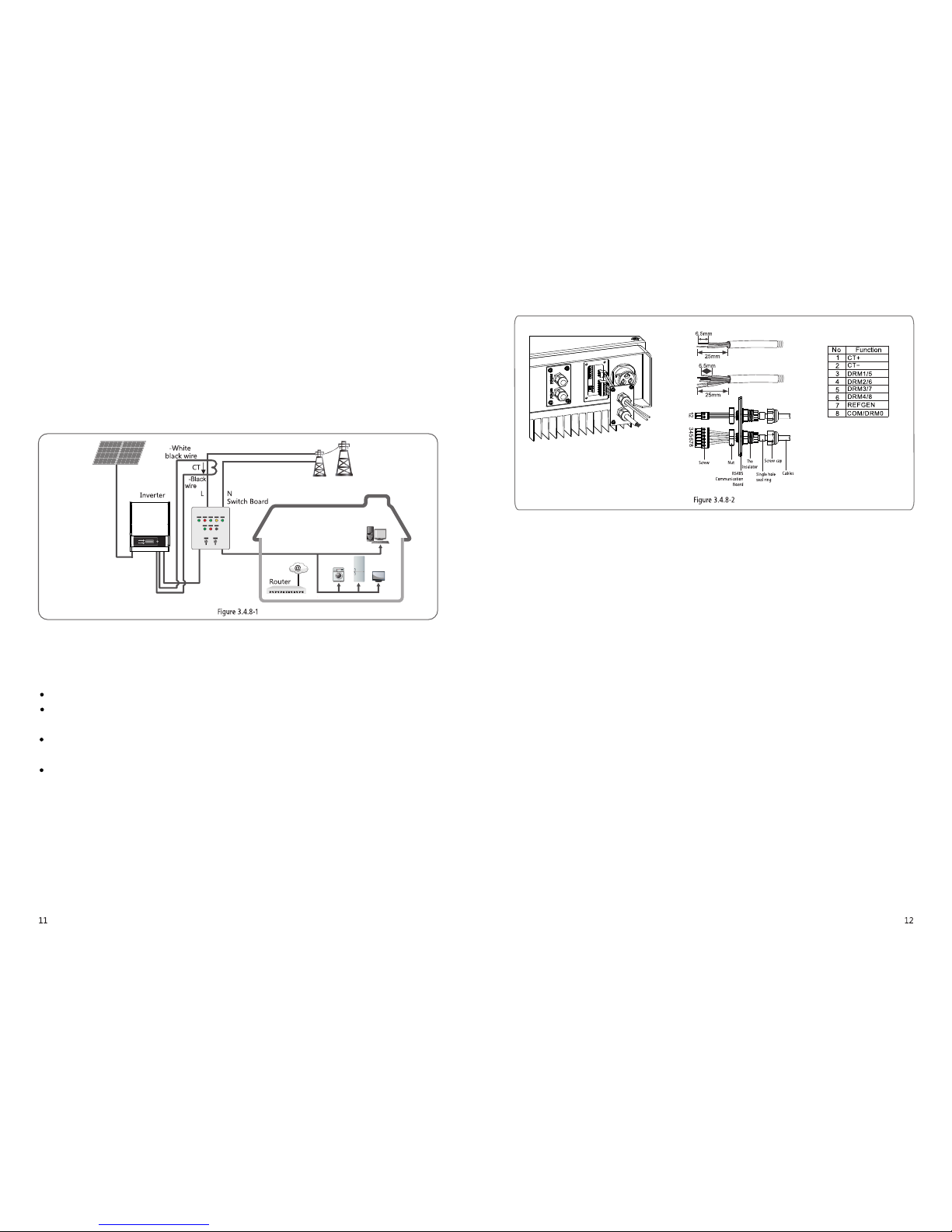
Connecti on method of Power Limiting device CT pleas e refer to Figure 3.4.8-1.
NOTE:
2-pi n termin al is used to m ake conne ction to CT d evice.You c an find it in a ccessor y bag.
6-pi n termin al is used to m ake conne ction to DR ED devic e. If DRE D device is n ot availa ble, pleas e keep it not co nnecte d.
Conn ection P rocedu re:
Put th e cable thr ough the c ompone nts in this o rder: scre w cap, one-h ole seal ing ring, in sulati on body an d sheet met al parts.
Pull o ut the 6-pi n termin al from the s ocket in th e cabinet a nd take off th e resist or which is f ixed in it .Cable sh ould be
conn ected as Fi gure 3.4. 8-2.
Inse rt the gree n termin al into th e corresp onding i nterio r termina l of the inv erter. Pull ca ble soft ly to maint ain the cab le not
to be pu lled out.
Lock t he sheet me tal part s onto the bo x and tight en the scr ew cap.
1.D RED con necti on is onl y availa ble for Austr alia an d New Zea land.
2.S uppor ted DRM c omman d: DRM0, DRM5, DRM6, DRM7, DRM8.
3.A fter in stall ation i s compl eted, pl ease se t up powe r limit ing fun ction r eferr ing to se ction 4 .2(6) .
4.Pa y atten tion to t he dire ction o f CT when wi ring. C T clip sh ould be l ocked ti ght. Whit e /Blac k cable s hould c onnec t Line 2,
bla ck cabl e shoul d conne ct Line 1 . Tight en them w ith scr ewdri ver. Make sur e CT cabl es conn ected t o the rig ht outp ut phas e lines
of in verte r when in u se.
5.W ithou t conne ction o f CT, inve rter wi ll show " CT Disc onnec t". If CT i s conne cted re verse ly, invert er will s how" CT R evers e
"wh en it ent ers int o on-gr id stat us.
3.4.9 Earth Fault Alarm
Page 9
Normal
Pac=2595.5W
E-Today= 15.2KWh
Pac=2595.5W
E-Total=533.17KWh
Pac=2595.5W
Vpv=325.5/325.5V
Pac=2595.5W
Ipv= 4.1/ 4.1A
Pac=2595.5W
Vac=229.5V
Pac=2595.5W
Iac=11.3A
Pac=2595.5W
Fac=50.00Hz
Pac=2595.5W
Error History
Pac=2595.5W
GWXXXXD-NS
Pac=2595.5W
Ver:V1.XX.XX
Pac=2595.5W
Set Time
Pac=2595.5W
WiFi Reset
Pac=2595.5W
WiFi Reload
Pac=2595.5W
PF Adjust
Pac=2595.5W
First Level Menu
Shadow MPPT ON
Pac=2595.5W
Shadow MPPT OFF
Pac=2595.5W
Short press
Short press
Short press
Long press 2S
Or
Short press
Short press
Short press
50Hz GridDefault
Lock
Long press 2S
Long press 2S
No Error
E01 110822 01:01
50Hz GridDefault
2000-00-00 00:00
2000-00-00 00:00
……
2000-00-00 00:0
0
Long
press 2S
Short press to set
The second number
WiFi Resetting
WiFi Reset OK
WiFi Reset Fail
WiFi Reloading
WiFi Reload Fail
WiFi Reload OK
Disable
lagging 0.95
lagging
0.95
lagging 0.95
Short press
Second Level Menu
Short press for
safety country select
Short press to select
leading or lagging
Short press to select
number 8 or 9
Short press to
select number 0~9
Long
press 2S
Set Language
Pac=2595.5W
English
Angielski
Short press
Short press
Short press
Short press
Short press
Short press
Short press
Short press
Short press
Short press
Short press
Short press
Short press
Short press
Short press
Long press 2S
Long press 2S
Long press 2S
Long press 2S
Long press 2S
Long press 2S
Short press to set
The third number
Short press to set
The last number
Long press 2S
Long press 2S
Wait 25S
Wait 25S
Long press 2S
Short press
Long press 2S
Long press 2S
WiFi
RS485
Power Limit ON
Pac=2595.5W
Power Limit OFF
Pac=2595.5W
Long press 2S
Short press
Short press
Set Power Limit
XXX%
Set Power Limit
XXX%
Set Power Limit
X %X
Set Power Limit
XX%
Short press to
select number 0~9
Short press to
select number 0~9
Short press to
select number 0~1
Long press 2S
Long press 2S
Long
press 2S
Long press 2S
Or
Set Modbus Addr
Pac=2595.5W
Short press
Long press 2S
Set Addr
:X
XX
Set Addr
: XX X
Set Addr :
XXX
Short press to
select number 0~9
Short press to
select number 0~2
Long press 2S
Long press 2S
Long
press 2S
Short press to
select number 0~9
4 System Operation
4.1 Indicator Lights
Indicator lights in Yellow/Green/Red correspondently refer to
ON = WiFi C ONNEC TED / ACTI VE
BLINK 1 = W iFi SYS TEM RES ETTIN G
BLINK 2 = W iFi ROU TER PRO BLEM
BLINK 4 = W iFi SER VER PRO BLEM
BLINK = R S485 CO NNECT ED
OFF = WiF i NOT ACTI VE
ON = INVE RTER IS F EEDIN G POWER
OFF= IN VERTE R IS NOT FE EDING P OWERAT TH E MOMEN T
ON = FAULT OC CURRE D
OFF = NO FAU LT
4.2 User interface and use of the display
Set Safety Count ry:
If display shows 'C onfigure Safety', then long pres s (2S) the key to enter the second lev el menu. Short press to browse the safety
country avail able. Choose suita ble safety country accord ing to the location of installati on. The inverter will store the chos en safety
country afte r 20 seconds of no operat ion.
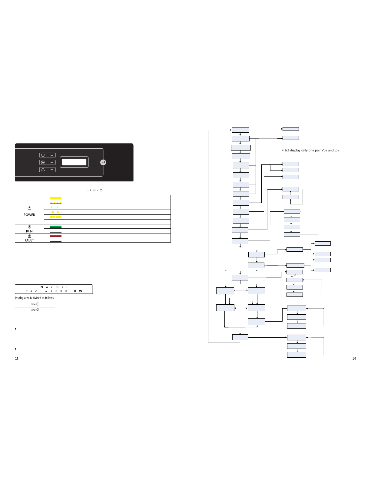
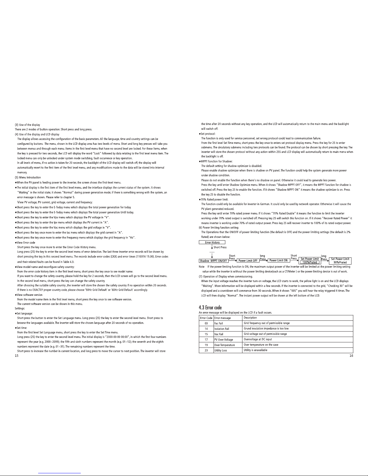
(1) A schematic of the display scr een is shown as below:
(2) Display area
Line①---Wo rking status informat ion
This area displays the status info rmation. "Waiting" indicat es the inverter is standby for power gen eration; "Checking **S"
(checkin g time is based on safety, and varies from count ry to country) indicates the inv erter is self-checking , counting down and
preparin g for power gener ation. "Normal" indicate s the inverter is gen erating power. If any condition of the system is abnorma l, the
screen will disp lay an error message. Refer to Table 4.3.
Through key operation, the screen can disp lay different informat ion such as operation paramet ers and power generation stat us in this
area. There are two levels of menus, and the flow chart of first leve l menu is shown below :
Page 10
Page 11
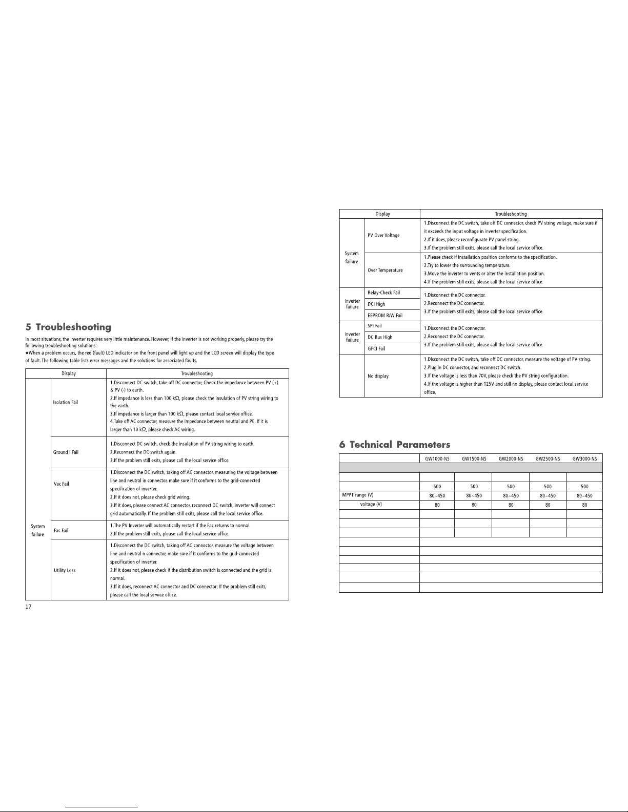
1300 1950 2600 3250 3900Max.DC Input Power(W)
Max.DC Input voltage(V)
Start-up
MPP T Range f or Full L oad (V)
Nom inal DC I nput Volt age (V)
Max . Inp ut Curr ent (A)
Max . Sho rt Curr ent (A)
No.of MPP Trackers
No.of In put Strin gs per Tracke r
PV Str ing Inp ut Data
Technical Dat a
120~45 0 180~45 0 230~45 0 180~45 0 215~45 0
360
10
360 360 360 360
10 10 18 18
12.5
1
1
PV Ov er Curr ent Pro tecti on(A)
DC over voltage c ategory
Catego ry II
20
4.5 Special Adjustable Setpoints
The inverter has field adjustable function,such as trip points,trip times, reconnect times,active and invalid of QU curve,PU curve.
It is adjustable through special software ,if you want to use it ,plaese contact with after sales.
The methods document of using the software can download from goodwe website or contact with after sales.
PV Ba ckfee d Curre nt(A)
0
18
4.4 Wi-Fi Reset & Wi-Fi Reload
The two functions are onl y available for Wi-Fi model inve rters.
Wi-Fi reload funct ion is used to change the Wi-Fi configuration to defa ult value. Please confi gure the Wi-Fi again as 3.4.5 after using
the function .
Press the key until the LCD displ ays "Wi-Fi Reset", then long press (2S) until th e LCD displays "Wi -Fi Resetting...". Stop press ing and
wait for the screen show ing "Wi-Fi Reset OK" or "Wi-Fi Reset Failed".
Press the key until the LCD displ ays "Wi-Fi Reload", then long press (2S) unti l the LCD displays "Wi-Fi Reloading ...". Stop pressing and
wait for the screen show ing "Wi-Fi Reload OK" or "Wi-Fi Reload Failed".
Note: When sunlight is insuff icient, the PV Inverter may contin uously start up and shut down automat ically due to insufficien t
power genera ted by the PV panels, which would not lead to inverter damag e. If the problem still exits, please cal l the local service
office.
Page 12
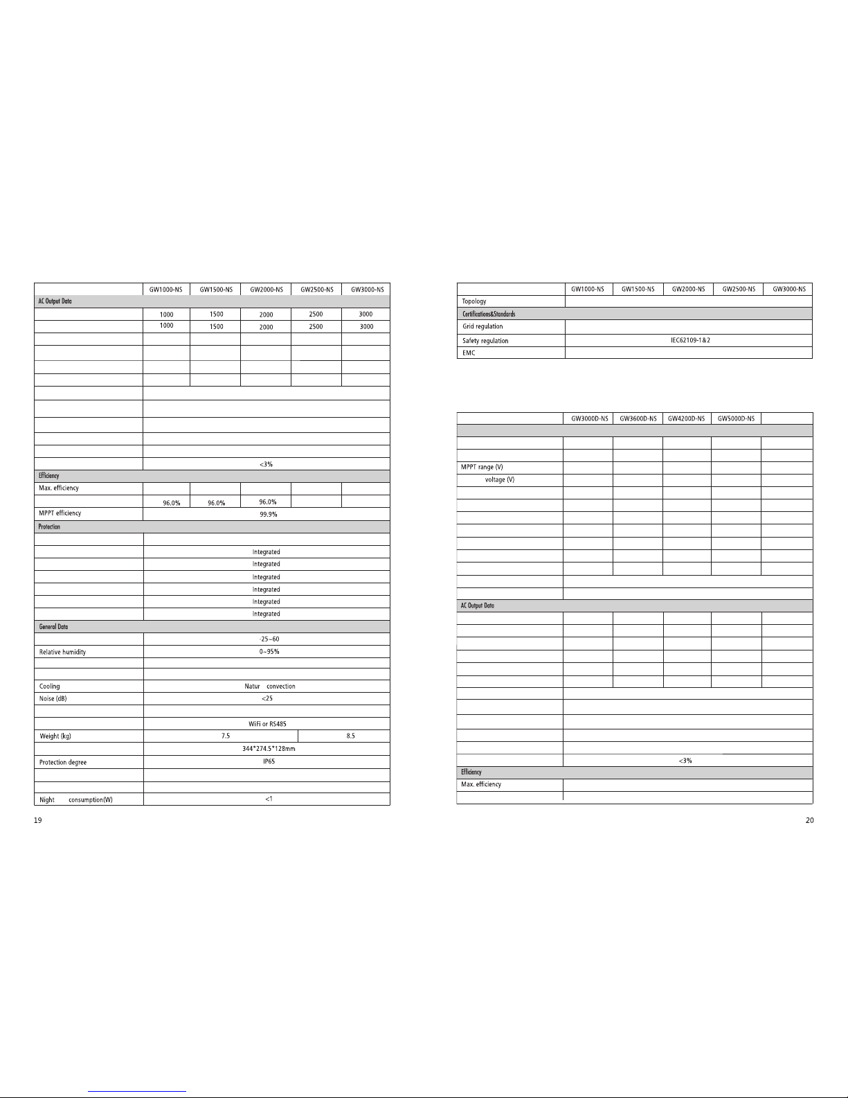
Technical Dat a
Nomin al Output Frequ ency(Hz)
Max. Outp ut Current (A )
Outpu t Power Factor
Outpu t THDi (@N omina Outpu t)
50/60 50/60 50/60 5 0/60 50/60
5
7.5
10 12 .5 13.5
~1(Ad justable f rom 0.8 leadin g to 0.8 laggin g)
Europ e efficien cy
96.5% 97.0% 97.0% 97.5%97.5%
97.0%
97.0%
Anti- islandin g Protecti on
Input R everse Polar ity Protect ion
Insul ation Resi stor Detect ion
Resid ual Curren t Monitorin g Unit
Outpu t Over Curren t Protectio n
Outpu t Short Prote ction
Outpu t Over Voltage Prot ection
Opera ting Temperatur e Range(℃)
Opera ting Altitud e(m)
User In terface
Commu nication
Size Width*H eight*De pth mm( )
self
≤4000
al
LCD&L ED
VDE0126-1-1,AS4777.2,EN50438(PL),G83,ERDF-NOI-RES_13E,IEC61727,IEC62116
EN 61000-6-1,EN 61000-6-2,EN 61000-6-3,EN 61000-6-4
3900 4680 5460 6500Max.DC Input Power(W)
Max.DC Input voltage(V)
Start-up
MPP T Range f or Full L oad (V)
Nom inal DC I nput Volt age (V)
Max . Inp ut Curr ent (A)
Max . Sho rt Curr ent (A)
No.of MPP Trackers
No.of In put Strin gs per Tracke r
PV Str ing Inp ut Data
Technical Dat a
Nom inal Ou tput Pow er (W)
Max. Outp ut Apparent Powe r (VA)
Nomin al Output Voltag e (V)
150~45 0 180~45 0 210~45 0 250~45 0
360
11/11
360 360 360
13.8/1 3.8
2
1 1 1 1
220~23 0 220~230 220 ~230 220~230
Nomin al Output Frequ ency(Hz)
Max. Outp ut Current (A )
Outpu t Power Factor
Outpu t THDi (@N omina Outpu t)
50/60 50/60 5 0/60 50 /60
13.6
16
19 22.8
~1(Ad justable f rom 0.8 leadin g to 0.8 laggin g)
Europ e efficien cy
97.8%
580
80~550
120
580
580 580
80~550 80~550 80~55 0
120 120 120
11/11 11/11 11/11
13.8/1 3.8 13.8/ 13.8 13.8/13.8
2 2 2
3000 3680 4200 5000
3000 3680 4200 5000
97.5%
AC overc urrent prot ection (A)
7 11 15
2019
AC overv oltage cate gory
Categ ory III
Maxim um output fau lt current a. c. A
(peak a nd duration )
0
Moist ure locati on category
4K4H
Environment category Outdoor&Indoor
External environment pollution degree
Grade1、2、 3
Nom inal Ou tput Pow er (W)
Max. Outp ut Apparent Powe r (VA)
Nomin al Output Voltag e (V)
220~23 0 220~230 220~23 0 220~230 220~23 0
PV Ov er Curr ent Pro tecti on(A)
DC over voltage c ategory
Catego ry II
PV Back up Curren t(A)
0
AC overc urrent prot ection (A)
24 29 35
GW5KD-NS
6500
250~45 0
360
1
580
80~550
120
11/11
13.8/1 3.8
2
220~23 0
50/60
21.7
4600
4950
3520
25/25 25/25 25 /25 25 /25 25/ 25
Outpu t Inrush Curr ent
(peak a nd duration )
AC Backf eed Current (A)
High Frequency Isolation
Integ rated (AFD)
50A 100 μs
25A 5μs
Technical Dat a
AC overv oltage cate gory(A)
Maxim um output fau lt current
a.c. A(peak a nd duration )
Outpu t Inrush Curr ent
(peak a nd duration )
AC Backf eed Current (A)
Categ ory III
0
50A 100 μs
25A 5μs
Page 13
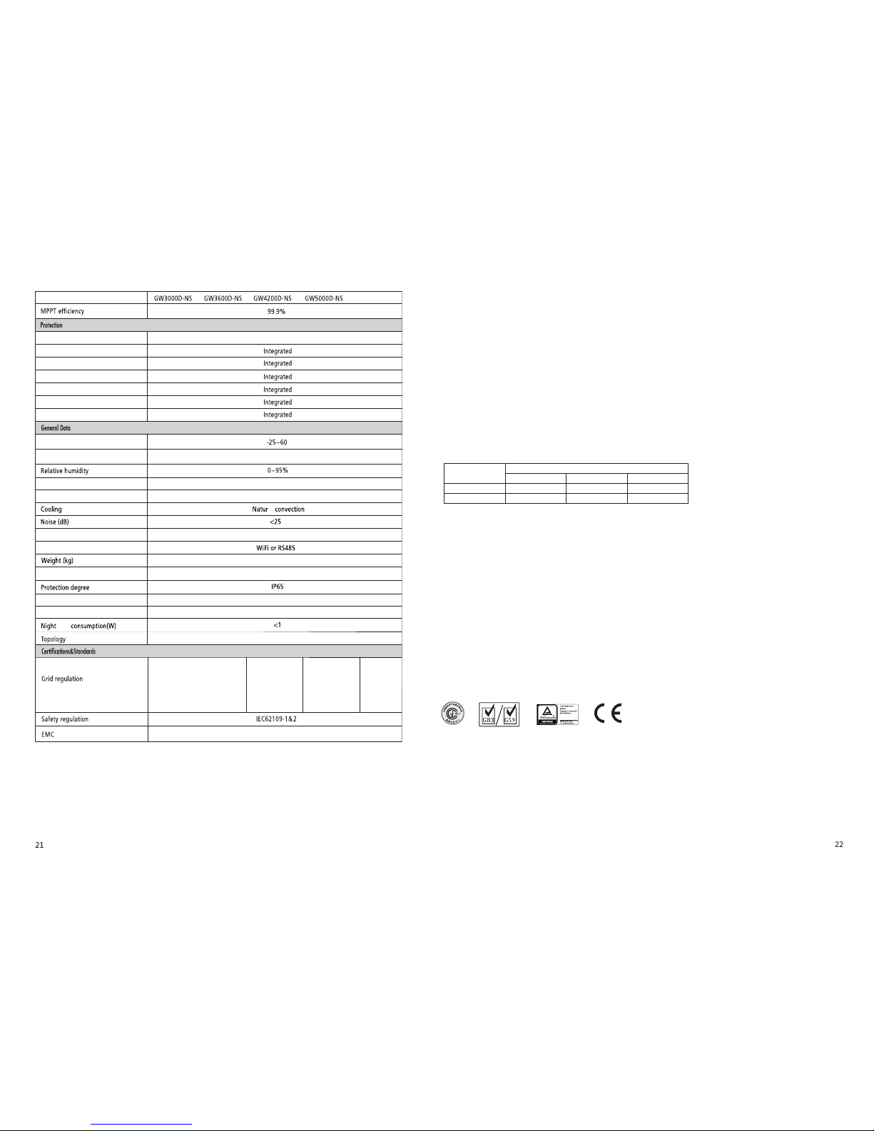
Opera ting Altitud e(m)
User In terface
Commu nication
Size Width*H eight*De pth mm( )
self
≤4000
al
LCD&L ED
VDE-AR-N 4105,
VDE0126-1-1
EN50438(PL),
EN50438(SW),G83,
IEC61727,AS4777.2
IEC62116
EN6100-6-1,EN61000-6-2,EN61000-6-3,EN61000-6-4
Technical Dat a
14
347*4 32*145mm
VDE-AR-N 4105
VDE0126-1-1
EN50438(PL),
EN50438(SW),G59,
IEC61727,AS4777.2
IEC62116
VDE-AR-N 4105
VDE0126-1-1
EN50438(PL),
EN50438(SW),G59,
IEC61727,AS4777.2
IEC62116,MEA,PEA
Moist ure locati on category
4K4H
Environment category Outdoor&Indoor
External environment pollution degree
Grade1、2、 3
GW5KD-NS
AS4777.2
IE C62 109 -2 VD E01 26- 1-1
Spe cial Adj ustab le Setp oints
The in verte r has fie ld adju stabl e funct ion,s uch as tr ip poin ts,tri p times, re conne ct time s,act ive and i nvalid o f QU curv e,PU
cur ve.
It is a djust able th rough s pecia l softwa re ,if yo u want to u se it ,pl aese co ntact w ith aft er sale s.
The me thods d ocume nt of usi ng the so ftwar e can down load fr om good we webs ite or co ntact w ith aft er sale s.
8 Maintenance
Insul ation Resi stor Detect ion
Resid ual Curren t Monitorin g Unit
Outpu t Over Curren t Protectio n
Outpu t Short Prote ction
Outpu t Over Voltage Prot ection
Opera ting Temperatur e Range(℃)
Anti- islandin g Protecti on
Input R everse Polar ity Protect ion
Integ rated (AFD)
Stora ge Tempera ture (℃)
-30~6 5
High Frequency Isolation
Note
Overvoltage category definition
Category I: applies to equipment connected to a circuit where measures have been taken to reduce transient overvoltage to a
low level.
Category II: applies to equipment not permanently connected to the installation. Examples are appliances, portable tools and
other plug-connected equipment;
Category III: applies to fixed equipment downstream of and including, the main distribution board. Examples are switchgear and
other equipment in an industrial installation;
Category IV: applies to equipment permanently connected at the origin of an installation (upstream of the main distribution board)
Example are electricity meters, primary overcurrent protection equipment and other equipment connected directly to
outdoor open lines.
Moisture location category definition
Moisture parameters
Temperature Range
Humidity Range
3K3
0~+40℃
5%~85%
4K2
-33~+40℃
15%~100%
4K4H
-20~+55℃
4%~100%
Level
Environment category definition
Outdoor : the ambient air temperature is -20~50 , Relative humidity range is 4%to 100%,applied to PD3
Indoor unconditioned: the ambient air temperature is -20~50 , Relative humidity range is 5%to 95%,applied to PD3
Indoor conditioned: the ambient air temperature is 0~40 , Relative humidity range is 5%to 85%,applied to PD2
℃
℃
℃
Pollution degree definition
Pollution degree 1: No pollution or only dry, non-conductive pollution occurs. The pollution has no influence.
Pollution degree 2: Normally only non-conductive pollution occurs. Occasionally, however, a temporary conductivity caused by
condensation must be expected.
Pollution degree 3: Conductive pollution occurs, or, dry, non-conductive pollution occurs which becomes conductive due to
condensation which is expected.
Pollution degree 4: Persistent conductive pollution occurs, for example, the pollution cause by conductive dust, rain and snow.
**: Plea se make sure the volt age of PV string wil l not exceed the Ma x. DC volta ge.
7 Certificates
 Loading...