

Page 1
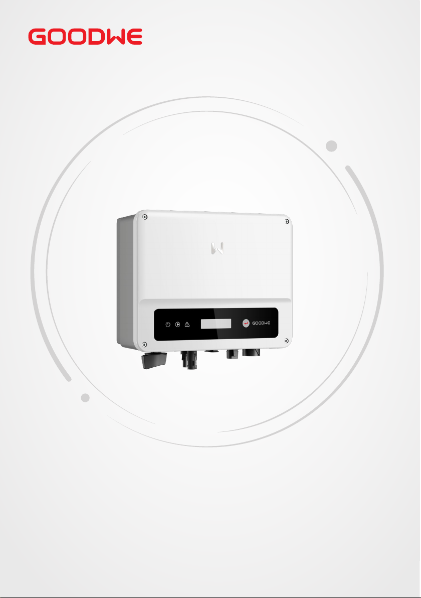
User Manual
Grid-Tied PV Inverter
XS Series
0.7-3.3kW
V1.3-2023-05-15
Page 2

User Manual V1.3-2023-05-15
Copyright Statement
Copyright ©GoodWe Technologies Co., Ltd., 2023. All rights reserved
No part of this manual can be reproduced or transmitted to the public platform in any form or
by any means without the prior written authorization of GoodWe Technologies Co., Ltd.
Trademarks
and other GOODWE trademarks are trademarks of GoodWe Technologies
Co.,Ltd. All other trademarks or registered trademarks mentioned in this manual are owned by
GoodWe Technologies Co.,Ltd.
NOTICE
The information in this user manual is subject to change due to product updates or other
reasons. This guide cannot replace the product labels or the safety precautions in the user
manual unless otherwise specied. All descriptions here are for guidance only.
I
Page 3

CONTENT
User Manual V1.3-2023-05-15
CONTENT
1 About This Manual .................................................................1
1.1 Applicable Model .......................................................................................... 1
1.2 Target Audience ............................................................................................1
1.3 Symbol Denition ......................................................................................... 2
1.4 Updates .........................................................................................................2
2 IMPORTANT SAFETY INSTRUCTIONS ....................................3
2.1 General Safety ..............................................................................................3
2.2 DC Side ..........................................................................................................3
2.3 AC Side ...........................................................................................................4
2.4 Inverter Installation .....................................................................................4
2.5 Personal Requirements ...............................................................................5
3 Product Introduction .............................................................6
3.1 Application Scenarios ..................................................................................6
3.2 Circuit Diagram .............................................................................................6
3.3 Supported Grid Types ..................................................................................6
3.4 Appearance ...................................................................................................7
3.4.1 Parts ........................................................................................................................ 7
3.4.2 Dimensions ............................................................................................................ 8
3.4.3 Indicators ...............................................................................................................8
3.4.4 Nameplate .............................................................................................................9
4 Check and Storage ...............................................................10
4.1 Check Before Receiving .............................................................................10
4.2 Deliverables ................................................................................................10
4.3 Storage ........................................................................................................11
5 Installation ...........................................................................12
5.1 Installation Requirements .........................................................................12
5.2 Inverter Installation ...................................................................................15
5.2.1 Moving the Inverter ............................................................................................15
6 Electrical Connection ...........................................................16
II
Page 4

User Manual V1.3-2023-05-15
CONTENT
6.1 Safety Precaution .......................................................................................16
6.2 Connecting the PE Cable ...........................................................................17
6.3 Connecting the PV Input Cable ................................................................17
6.4 Connecting the AC Output Cable .............................................................20
6.5 Communication ..........................................................................................24
6.5.1 Communication Network Introduction ............................................................24
6.5.2 Connecting the Communication Cable (optional) ...........................................24
6.5.3 Connecting the RS485 Cable ............................................................................25
6.5.4 Connecting the Remote Shutdown Cable ......................................................26
6.5.5 Connecting the CT Cable ..................................................................................27
6.5.6 Connecting the DRED Cable ............................................................................28
6.5.7 Installing the Communication Module (optional) ...........................................29
6.5.8 Connecting the USB-RS485 Cable .....................................................................29
7 Equipment Commissioning .................................................30
7.1 Check Before Power ON ............................................................................30
7.2 Power On .....................................................................................................30
8 System Commissioning .......................................................31
8.1 Indicators and Buttons ..............................................................................31
8.2 Setting Inverter Parameters via LCD .......................................................31
8.2.1 Inverter Parameter Introduction ......................................................................33
8.3 Upgrading the Firmware Via USB Flash Disk ..........................................35
8.4 Setting Inverter Parameters via SolarGo App ........................................35
8.5 Monitoring via SEMS Portal .....................................................................35
9 Maintenance .........................................................................36
9.1 Power O the Inverter ...............................................................................36
9.2 Removing the Inverter ...............................................................................36
9.3 Disposing of the Inverter ..........................................................................36
9.4 Troubleshooting .........................................................................................36
9.5 Routine Maintenance .................................................................................39
10 Technical Parameters ........................................................40
III
Page 5
User Manual V1.3-2023-05-15
01 Disclaimer
1 About This Manual
This manual describes the product information, installation, electrical connection, commissioning,
troubleshooting, and maintenance. Read through this manual before installing and operating the
product. All the installers and users have to be familiar with the product features, functions, and
safety precautions. This manual is subject to update without notice. For more product details and
latest documents, visit https://en.goodwe.com.
1.1 Applicable Model
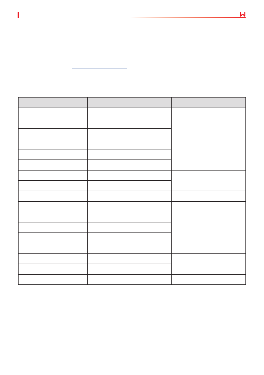
This manual applies to the listed inverters below (XS for short):
Model Nominal Output Power Nominal Output Voltage
GW700-XS 700W
GW1000-XS 1000W
GW1500-XS 1500W
GW2000-XS 2000W
GW2500-XS 2500W
GW3000-XS 3000W
GW2500N-XS 2500W
GW3000N-XS 3000W
GW3KB-XS 3000W 220V
GW3300-XS 3300W 230V
GW700-XS-11 700W
GW1000-XS-11 1000W
GW1500-XS-11 1500W
GW2000-XS-11 2000W
GW2500-XS-11 2500W
GW3000-XS-11 3000W
GW3000-XS-B11 3000W 220V
230V
220/230V
230V
220/230V
1.2 Target Audience
This manual applies to trained and knowledgeable technical professionals. The technical
personnel has to be familiar with the product, local standards, and electric systems.
1
Page 6
01 Disclaimer
User Manual V1.3-2023-05-15
1.3 Symbol Denition
Dierent levels of warning messages in this manual are dened as follows:
DANGER
Indicates a high-level hazard that, if not avoided, will result in death or serious injury.
WARNING
Indicates a medium-level hazard that, if not avoided, could result in death or serious injury.
CAUTION
Indicates a low-level hazard that, if not avoided, could result in minor or moderate injury.
NOTICE
Highlight and supplement the texts. Or some skills and methods to solve product-related
problems to save time.
1.4 Updates
The latest document contains all the updates made in earlier issues.
V1.0 2022-10-30
• First Issue
V1.1 2023-02-15
• Update 10 Technical Parameters.
V1.2 2023-04-15
• Update 6.5.2 Connecting the Communication Cable (optional).
V1.3 2023-05-15
• Update 10 Technical Parameters.
2
Page 7
User Manual V1.3-2023-05-15
02 Safety Precaution
2 IMPORTANT SAFETY INSTRUCTIONS
SAVE THESE INSTRUCTIONS
Please strictly follow these safety instructions in the user manual during the operation.
NOTICE
The inverters are designed and tested strictly complies with related safety rules. Read and
follow all the safety instructions and cautions before any operations. Improper operation might
cause personal injury or property damage as the inverters are electrical equipment.
2.1 General Safety
NOTICE
• The information in this user manual is subject to change due to product updates or other
reasons. This guide cannot replace the product labels or the safety precautions in the user
manual unless otherwise specied. All descriptions here are for guidance only.
• Before installations, read through the quick installation guide. For additional information,
please see the user manual.
• All installations should be performed by trained and knowledgeable technicians who are
familiar with local standards and safety regulations.
• Use insulating tools and wear personal protective equipment when operating the
equipment to ensure personal safety. Wear anti-static gloves, cloths, and wrist strips when
touching electron devices to protect the inverter from damage.
• Strictly follow the installation, operation, and conguration instructions in this manual.
The manufacturer shall not be liable for equipment damage or personal injury if you do
not follow the instructions. For more warranty details, please visit https://en.goodwe.com/
warranty.
2.2 DC Side
DANGER
Connect the DC cables using the delivered PV connectors. The manufacturer shall not be liable
for the equipment damage if other connectors or terminals are used.
WARNING
• Ensure the component frames and the bracket system are securely grounded.
• Ensure the DC cables are connected tightly, securely and correctly.
• Measure the DC cable using the multimeter to avoid reverse polarity connection. Also, the
voltage should be under the permissible range.
• Do not connect the same PV to multiple inverters. Otherwise, the inverters may be
damaged.
• The PV modules used with the inverter must have an IEC61730 class A rating.
3
Page 8
02 Safety Precaution
User Manual V1.3-2023-05-15
2.3 AC Side
WARNING
• The voltage and frequency at the connection point meet the inverter grid connection
requirements
• Additional protective devices like circuit breakers or fuses are recommended on the AC
side. Specication of the protective device should be at least 1.25 times the rated AC output
rated current.
• Make sure that all the groundings are tightly connected.
• You are recommended to use copper cables as AC output cables. Contact the manufacturer
if you want to use other cables.
2.4 Inverter Installation
DANGER
• Do not apply mechanical load to the terminals, otherwise the terminals can be damaged.
• All labels and warning marks should be visible after the installation. Do not scrawl,
damage, or cover any label on the device.
• Testing to AS/NZS 4777.2:2020 for multiple inverter combinations has not been conducted.
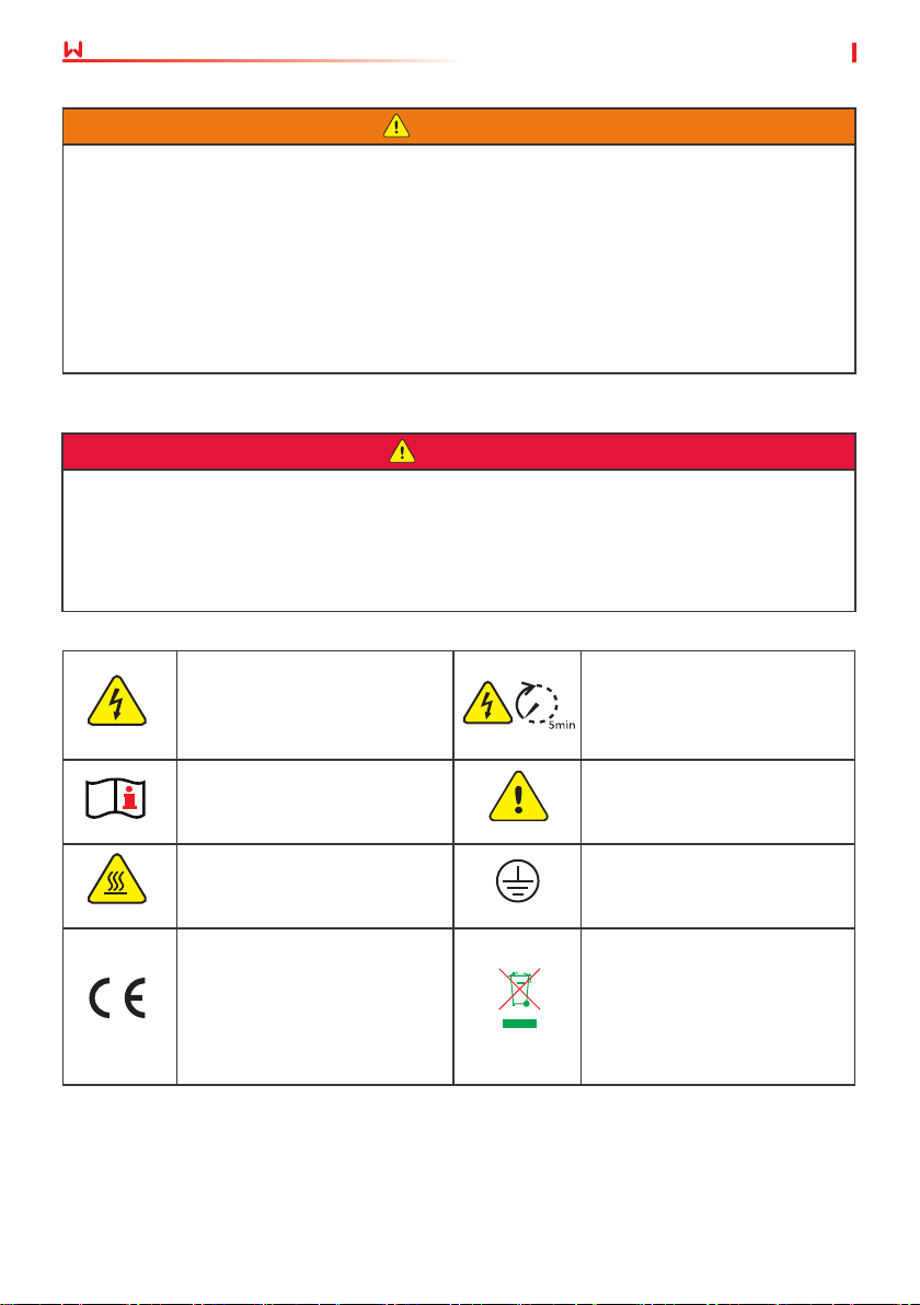
• Warning labels on the inverter are as follows.
DANGER High voltage hazard.
Disconnect all incoming power
and turn o the product before
working on it.
Read through the user manual
before working on this device.
High-temperature hazard. Do
not touch the product under
operation to avoid being burnt.
CE Mark Do not dispose of the inverter
Delayed discharge. Wait
5 minutes after power o
until the components are
completely discharged.
Potential risks exist. Wear
proper PPE before any
operations.
Grounding point.
as household waste. Discard
the product in compliance with
local laws and regulations,
or send it back to the
manufacturer.
4
Page 9
User Manual V1.3-2023-05-15
02 Safety Precaution
2.5 Personal Requirements
NOTICE
• Personnel who install or maintain the equipment must be strictly trained, learn about
safety precautions and correct operations.
• Only qualied professionals or trained personnel are allowed to install, operate, maintain,
and replace the equipment or parts.
2.6 EU Declaration of Conformity
GoodWe Technologies Co., Ltd. hereby declares that the inverter with wireless communication
modules sold in the European market meets the requirements of the following directives:
• Radio Equipment Directive 2014/53/EU (RED)
• Restrictions of Hazardous Substances Directive 2011/65/EU and (EU) 2015/863 (RoHS)
• Waste Electrical and Electronic Equipment 2012/19/EU
• Registration, Evaluation, Authorization and Restriction of Chemicals (EC) No 1907/2006 (REACH)
GoodWe Technologies Co., Ltd. hereby declares that the inverter without wireless communication
modules sold in the European market meets the requirements of the following directives:
• Electromagnetic compatibility Directive 2014/30/EU (EMC)
• Electrical Apparatus Low Voltage Directive 2014/35/EU (LVD)
• Restrictions of Hazardous Substances Directive 2011/65/EU and (EU) 2015/863 (RoHS)
• Waste Electrical and Electronic Equipment 2012/19/EU
• Registration, Evaluation, Authorization and Restriction of Chemicals (EC) No 1907/2006 (REACH)
You can download the EU Declaration of Conformity on https://en.goodwe.com.
5
Page 10
03 Product Introduction
User Manual V1.3-2023-05-15
3 Product Introduction
3.1 Application Scenarios
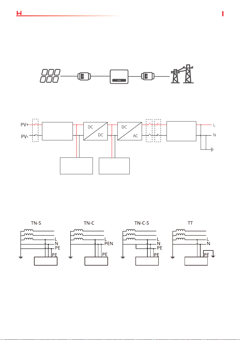
The inverter is a single-phase PV string grid-tied inverter, which converts the DC power
generated by the PV module into AC power for loads or the grid. The intended use of the
inverter is as follows:
PV String
Circuit Breaker
(optional)
Inverter
Circuit
Breaker
Utility
Grid
3.2 Circuit Diagram
DC Switch
I/P Filter &
surge Voltage
protection
PV insulation
check
Power Supply
EMI Filter &
surge Voltage
protection
Mains relay
Mains bridge relay
3.3 Supported Grid Types
For the grid type with neutral wire, the N to ground voltage must be less than 10V.
Inverter Inverter Inverter Inverter
6
Page 11
User Manual V1.3-2023-05-15
3.4 Appearance
3.4.1 Parts
03 Product Introduction
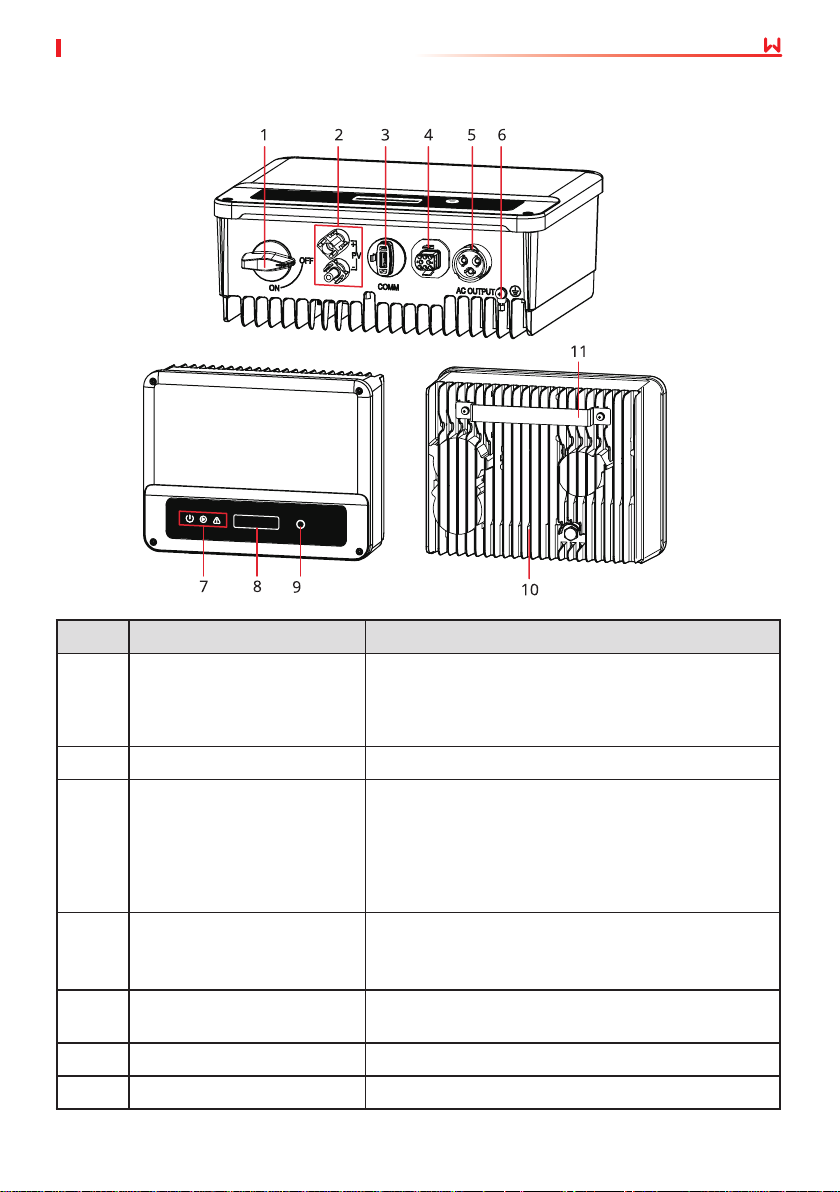
No. Parts Description
Optional. During normal operation it is in "on" state,
1 DC Switch(optional)
2 PV Input Terminal Used to connect the PV module DC input cables.
3
4
5 AC Output Terminal
6 PE Terminal Used to connect the PE cable.
7 Indicator Indicates working state of the inverter.
WiFi/LAN/4G Communication
Module Port
RS485/DRED/CT/Remote
Shutdown Communication
Cable Port(optional)
it can shut down the inverter after it is disconnected
from the grid by the AC breaker.
For Australia and New Zealand: With DC Switch.
• Connect a communication module like Bluetooth,
WiFi, LAN, 4G, etc. The module type may dier
depending on actual needs.
• Connect the USB-RS485 cable in Brazil.
• Update the software version of the inverter using
a USB ash driver.
Optional. Used to connect the RS485, DRED, CT, or
Remote Shutdown communication cable.
Used to connect the AC output cable, which connects
the inverter and the utility grid.
7
Page 12
03 Product Introduction
No. Parts Description
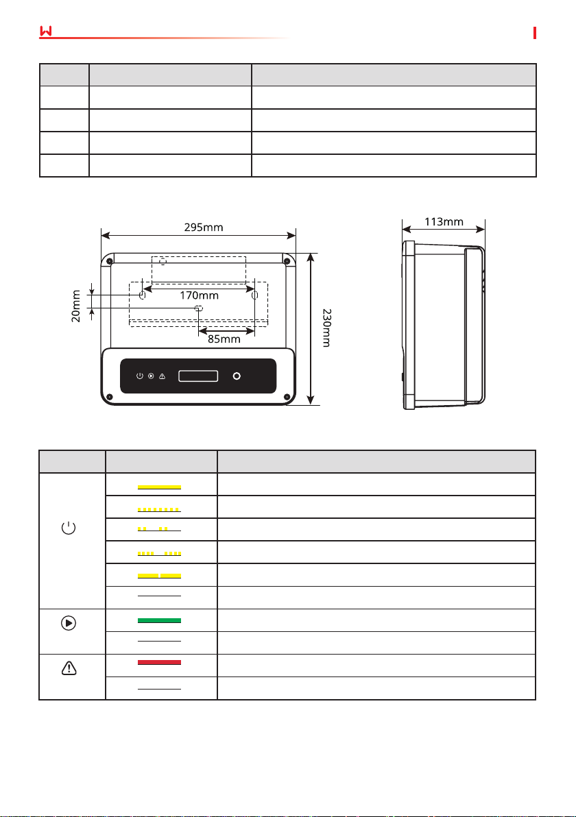
8 LCD Used to check the parameters of the inverter.
9 Button Used to select menus displayed on the screen.
10 Heat Sink Used to cool the inverter.
11 Mounting Plate Used to install the inverter.
User Manual V1.3-2023-05-15
3.4.2 Dimensions
3.4.3 Indicators
Indicator Status Description
ON = WiFi is connected/active.
BLINK 1 = WiFi system is resetting.
Power
Operating
Faulty
BLINK 2 = WiFi not connect to the router.
BLINK 4 = WiFi server problem.
BLINK = RS485 is connected.
OFF = WiFi is not active.
ON = The inverter is feeding power.
OFF = The inverter is not feeding power at the moment.
ON = A fault has occurred.
OFF = No fault.
8
Page 13
User Manual V1.3-2023-05-15
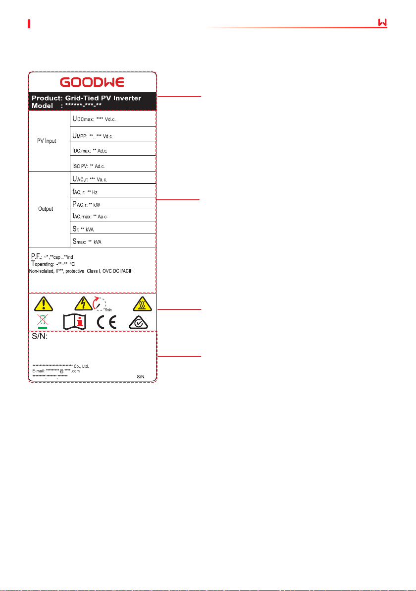
3.4.4 Nameplate
The nameplate is for reference only.
03 Product Introduction
GW trademark, product type, and
product model
Technical parameters
Safety symbols and certication
marks
Contact information and serial
number
9
Page 14
04 Check and Storage
User Manual V1.3-2023-05-15
4 Check and Storage
4.1 Check Before Receiving
Check the following items before receiving the product.
1. Check the outer packing box for damage, such as holes, cracks, deformation, and other
signs of equipment damage. Do not unpack the package and contact the supplier as soon as
possible if any damage is found.
2. Check the inverter model. If the inverter model is not what you requested, do not unpack the
product and contact the supplier.
3. Check the deliverables for correct model, complete contents, and intact appearance. Contact
the supplier as soon as possible if any damage is found.
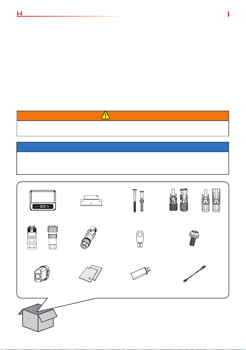
4.2 Deliverables
WARNING
Connect the DC cables with the delivered terminals. The manufacturer shall not be liable for
the damage if other terminals are used.
NOTICE
• Communication module types: WiFi, LAN, Bluetooth, 4G, etc. The actual module delivered
depends on the communication method of the selected inverter.
• USB-RS485 cable is only for Brazil.
Inverter x 1
or
AC connector x 1
Communication
Module x N
Mounting plate x 1
Communication
Connector x 1
Documentation x 1
or
Expansion bolt x 3
OT terminal x 1 Screw x 1
Bluetooth Module x N USB-RS485 cable x N
PV connector x 1
10
Page 15

User Manual V1.3-2023-05-15
04 Check and Storage
4.3 Storage
If the equipment is not to be installed or used immediately, please ensure that the storage
environment meets the following requirements:
1. Do not unpack the outer package or throw the desiccant away.
2. Store the equipment in a clean place. Make sure the temperature and humidity are
appropriate and no condensation.
3. The height and direction of the stacking inverters should follow the instructions on the
packing box.
4. The inverters must be stacked with caution to prevent them from falling.
5. If the inverter has been long term stored, it should be checked by professionals before being
put into use.
11
Page 16
05 Installation
User Manual V1.3-2023-05-15
5 Installation
5.1 Installation Requirements
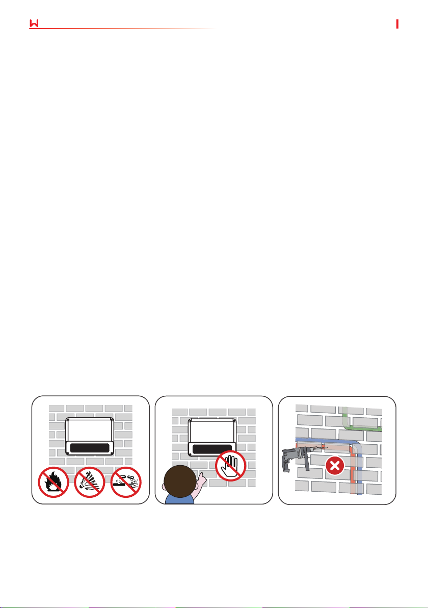
Installation Environment Requirements
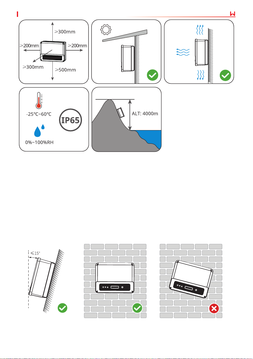
1. Do not install the equipment in a place near ammable, explosive, or corrosive materials.
2. Install the equipment on a surface that is solid enough to bear the inverter weight.
3. Install the equipment in a well-ventilated place to ensure good dissipation. Also, the
installation space should be large enough for operations.
4. The equipment with a high ingress protection rating can be installed indoors or outdoors.
The temperature and humidity at the installation site should be within the appropriate range.
5. Install the equipment in a sheltered place to avoid direct sunlight, rain, and snow. Build a
sunshade if it is needed.
6. Install the equipment in a well-ventilated place to ensure good dissipation. Also, the
installation space should be large enough for operations.
7. Do not install the equipment in a place that is easy to touch, especially within children’s
reach. High temperature exists when the equipment is working. Do not touch the surface to
avoid burning.
8. Install the equipment at a height that is convenient for operation and maintenance, electrical
connections, and checking indicators and labels.
9. The altitude to install the inverter shall be lower than the maximum working altitude 4000m.
10. The inverter is easy to be corroded when installed in salt areas. Please consult the inverter
manufacturer before installing it outdoors in salt areas. A salt area refers to the region
within 1000m oshore or aected by the sea breeze. The area prone to the sea breeze varies
depending on weather conditions (e.g. typhoon, monsoon) or terrain (such as dams and
hills).
11. Install the inverter away from high magnetic eld to avoid electromagnetic interference.If
there is any radio or wireless communication equipment below 30MHz near the inverter, you
have to:
• Install the inverter at least 30m far away from the wireless equipment.
• Add a low pass EMI lter or a multi winding ferrite core to the DC input cable or AC output
cable of the inverter.
Children No Touch
12
Page 17
User Manual V1.3-2023-05-15
Mounting Support Requirements
• The mounting support shall be nonammable and reproof.
• Make sure that the support surface is solid enough to bear the product weight load.
• Do not install the product on the support with poor sound insulation to avoid the noise
generated by the working product, which may annoy the residents nearby.
05 Installation
Installation Angle Requirements
• Install the inverter vertically or at a maximum back tilt of 15 degrees.
• Do not install the inverter upside down, forward tilt, back forward tilt, or horizontally.
13
Page 18
05 Installation
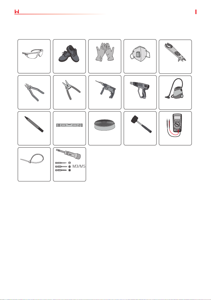
Installation Tool Requirements
The following tools are recommended when installing the equipment. Use other auxiliary tools
on site if necessary.
User Manual V1.3-2023-05-15
Goggles
Diagonal pliers Wire stripper Hammer drill Heat gun
Marker Level
Cable tie
Safety shoes
Torque wrench
Safety gloves
Heat shrink
tube
Dust mask
Rubber
hammer
DC wiring
wrench
Vacuum
cleaner
Multimeter
14
Page 19
User Manual V1.3-2023-05-15
05 Installation
5.2 Inverter Installation
5.2.1 Moving the Inverter
CAUTION
• Operations such as transportation, turnover, installation and so on must meet the
requirements of the laws and regulations of the country or region where it is located.
• Move the inverter to the site before installation. Follow the instructions below to avoid
personal injury or equipment damage.
1. Consider the weight of the equipment before moving it. Assign enough personnel to
move the equipment to avoid personal injury.
2. Wear safety gloves to avoid personal injury.
3. Keep balance to avoid falling down when moving the equipment.
NOTICE
• Avoid the water pipes and cables buried in the wall when drilling holes.
• Wear goggles and a dust mask to prevent the dust from being inhaled or contacting eyes
when drilling holes.
• The DC switch lock is prepared by the customer.
• Make sure the inverter is rmly installed in case of falling down.
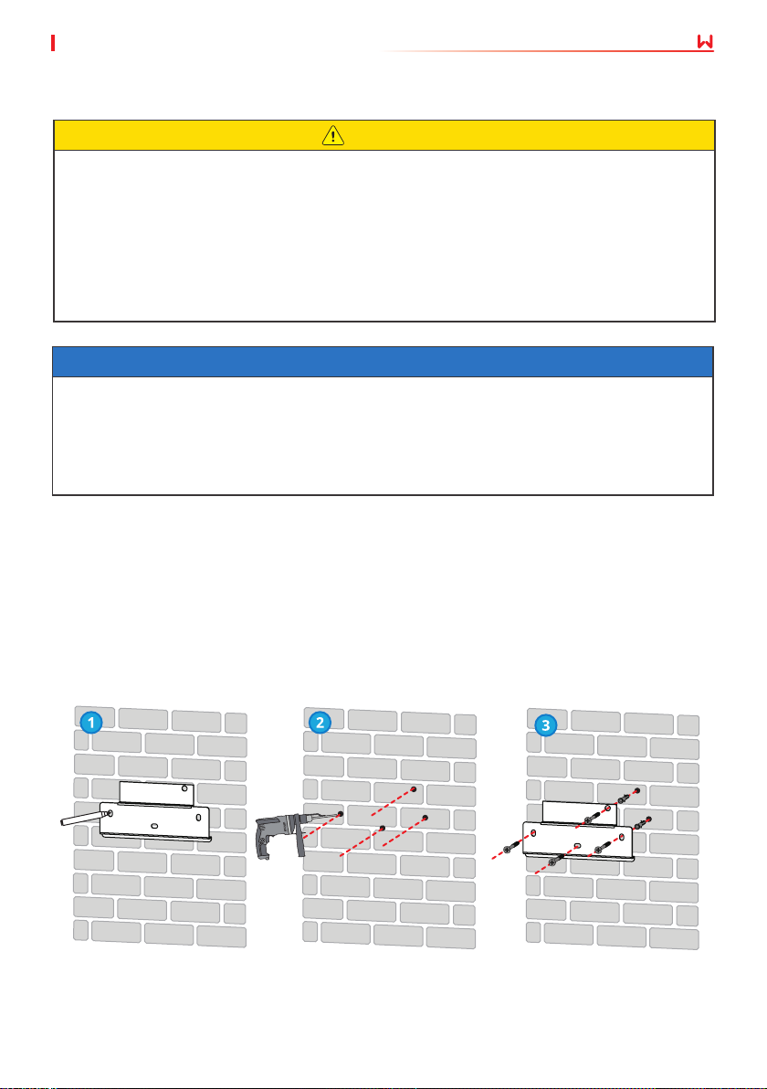
Step 1 Put the mounting plate on the wall or the support horizontally and mark positions for
drilling holes.
Step 2 Drill holes to a depth of 80mm using the hammer drill. The diameter of the drill bit
should be 10mm.
Step 3 Secure the mounting plate using the expansion bolts.
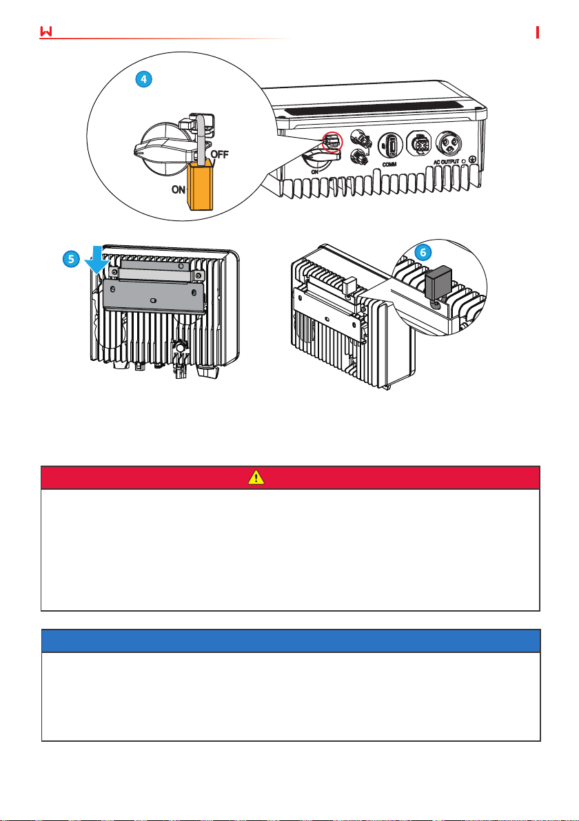
Step 4 (Only for Australia.) Install the DC switch lock.
Step 5 Install the inverter on the mounting plate.
Step 6 Install the anti-theft lock.
15
Page 20
05 Installation
For Australia only.
6 Electrical Connection
6.1 Safety Precaution
User Manual V1.3-2023-05-15
DANGER
• Disconnect the DC switch and the AC output switch of the inverter to power o the inverter
before any electrical connections. Do not work with power on. Otherwise, an electric shock
may occur.
• Perform electrical connections in compliance with local laws and regulations. Including
operations, cables, and component specications.
• If the cable bears too much tension, the connection may be poor. Reserve a certain length of
the cable before connecting it to the inverter cable port.
NOTICE
• Wear personal protective equipment like safety shoes, safety gloves, and insulating gloves
during electrical connections.
• All electrical connections should be performed by qualied professionals.
• Cable colors in this document are for reference only. The cable specications shall meet local
laws and regulations.
16
Page 21
User Manual V1.3-2023-05-15 06 Electrical Connection
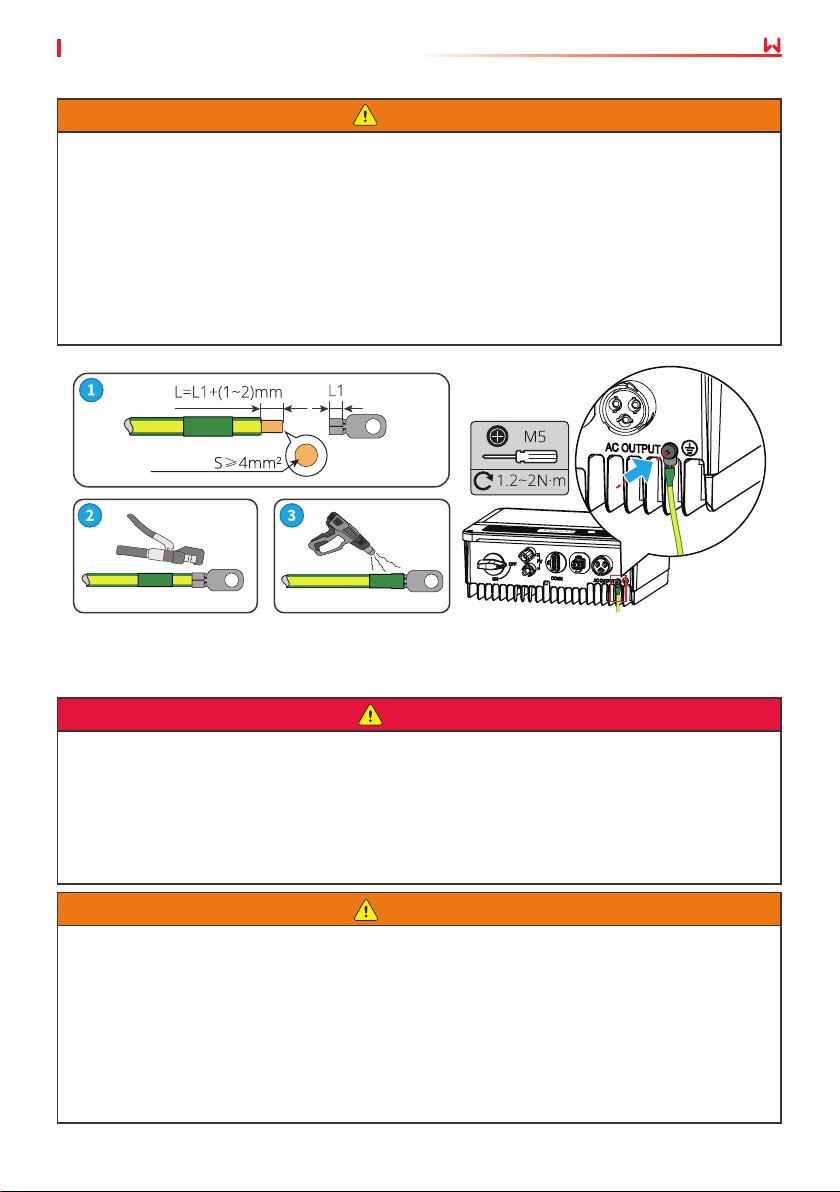
6.2 Connecting the PE Cable
WARNING
• The PE cable connected to the enclosure of the inverter cannot replace the PE cable
connected to the AC output port. Make sure that both of the two PE cables are securely
connected.
• Make sure that all the grounding points on the enclosures are equipotential connected
when there are multiple inverters.
• To improve the corrosion resistance of the terminal, you are recommended to apply silica
gel or paint on the ground terminal after installing the PE cable.
• The PE cable is prepared by the customer. Recommended specications:
• Type: single-core outdoor copper cable
• Conductor cross-sectional area: 4mm
Copper,
2
6.3 Connecting the PV Input Cable
DANGER
Conrm the following information before connecting the PV string to the inverter. Otherwise,
the inverter may be damaged permanently or even cause re and cause personal and property
losses.
1. Make sure that the max short circuit current and the max input voltage per MPPT are within
the permissible range.
2. Make sure that the positive pole of the PV string connects to the PV+ of the inverter. And the
negative pole of the PV string connects to the PV- of the inverter.
WARNING
• Connect the DC cables using the delivered PV connectors. The manufacturer shall not be
liable for the damage if other connectors are used.
• The PV strings cannot be grounded. Ensure the minimum isolation resistance of the
PV string to the ground meets the minimum isolation resistance requirements before
connecting the PV string to the inverter.
• The DC input cable is prepared by the customer. Recommended specications:
• Type: the outdoor photovoltaic cable that meets the maximum input voltage of the
inverter.
• Conductor cross-sectional area: 2.5~4mm
2
(Devalan) or 4~6mm2 (MC4).(MC4)
17
Page 22
User Manual V1.3-2023-05-1506 Electrical Connection
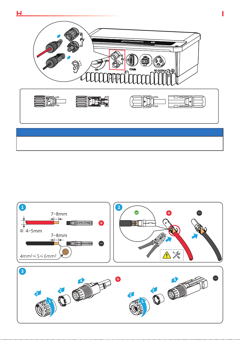
Click
DEVALAN Series MC4 Series
NOTICE
Seal the PV input terminals using waterproof covers when they are not to be used. Otherwise,
the ingress protection rating will be inuenced.
Connecting the DC Input Cable
Step 1 Prepare DC cables.
Step 2 Crimp the crimp contacts.
Step 3 Disassemble the PV connectors.
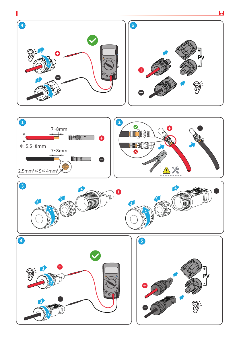
Step 4 Make the DC cable and detect the DC input voltage.
Step 5 Plug the PV connectors into the PV terminals.
MC4 PV connector
18
Page 23
User Manual V1.3-2023-05-15 06 Electrical Connection
GW2500N-XS, GW3000N-XS, GW3KB-XS,
GW2500-XS-11, GW3000-XS-11,GW3000XS-B11: ≤ 600V
Others: ≤ 500V
Click
Click
Devalan PV connector
GW2500N-XS, GW3000N-XS, GW3KB-XS,
GW2500-XS-11, GW3000-XS-11,GW3000XS-B11: ≤ 600V
Others: ≤ 500V
Click
Click
19
Page 24
User Manual V1.3-2023-05-1506 Electrical Connection
6.4 Connecting the AC Output Cable
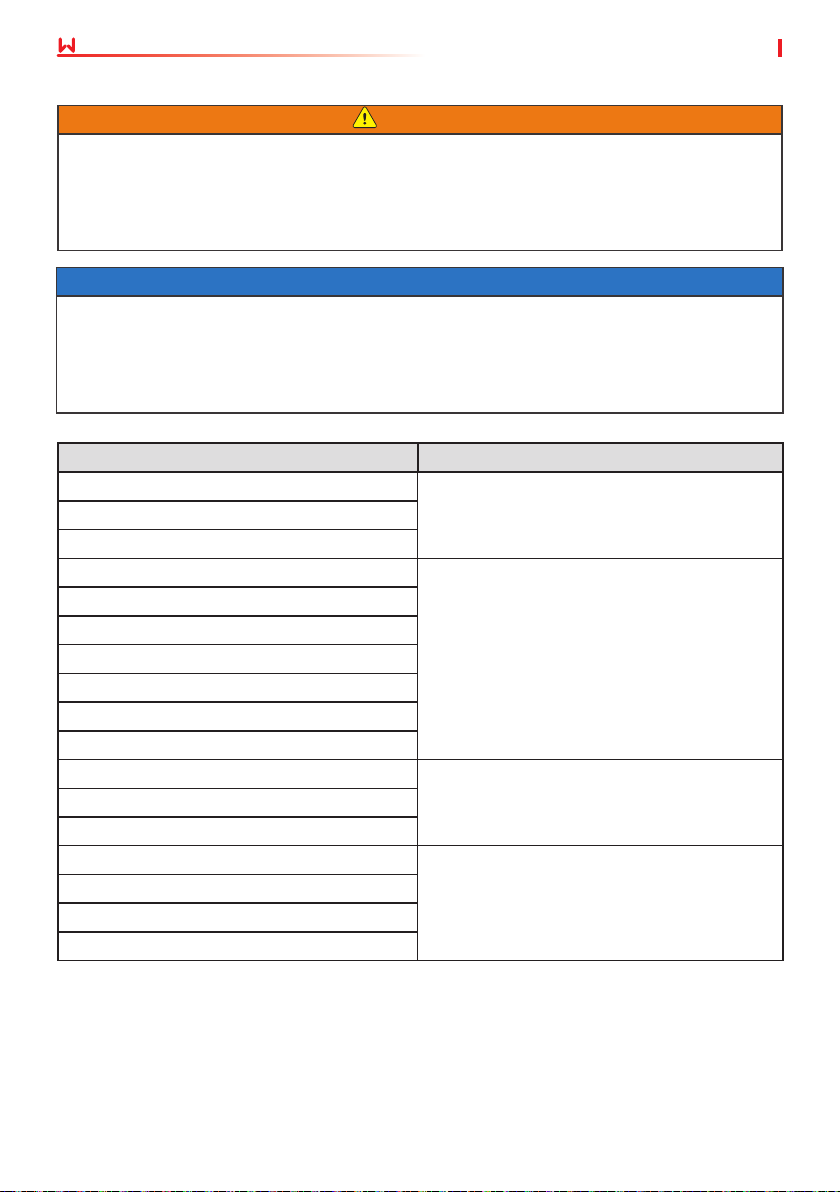
WARNING
• Do not connect loads between the inverter and the AC switch directly connected to the
inverter.
• The Residual Current Monitoring Unit (RCMU) is integrated into the inverter. The inverter
will disconnect the utility grid rapidly once it detects any leak current over the permissible
range.
NOTICE
• Install one AC circuit breaker for each inverter. Multiple inverters cannot share one AC circuit
breaker.
• An AC circuit breaker shall be installed on the AC side to make sure that the inverter can safely
disconnect the grid when an exception happens. Select the appropriate AC circuit breaker in
compliance with local laws and regulations. Recommended AC circuit breakers:
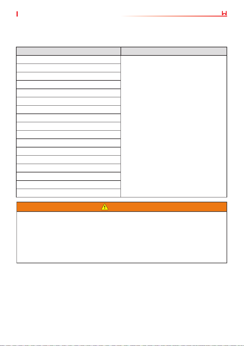
Inverter model AC circuit breaker
GW700-XS
16AGW1000-XS
GW1500-XS
GW2000-XS
GW2500-XS
GW3000-XS
GW2500N-XS
GW3000N-XS
GW3KB-XS
GW3300-XS
GW700-XS-11
GW1500-XS-11
GW2000-XS-11
GW2500-XS-11
GW3000-XS-11
GW3000-XS-B11
25A
16AGW1000-XS-11
25A
20
Page 25
User Manual V1.3-2023-05-15 06 Electrical Connection
Select and Install RCD depending on local laws and regulations.Type A RCDs (Residual Current
Monitoring Device) can be connected to the outside of the inverter for protection when the DC
component of the leakage current exceeds the limit value. The following RCDs are for reference:
Inverter model AC circuit breaker
GW700-XS
GW1000-XS
GW1500-XS
GW2000-XS
GW2500-XS
GW3000-XS
GW2500N-XS
GW3000N-XS
GW3KB-XS
GW3300-XS
GW700-XS-11
GW1000-XS-11
GW1500-XS-11
GW2000-XS-11
GW2500-XS-11
GW3000-XS-11
GW3000-XS-B11
300mA
WARNING
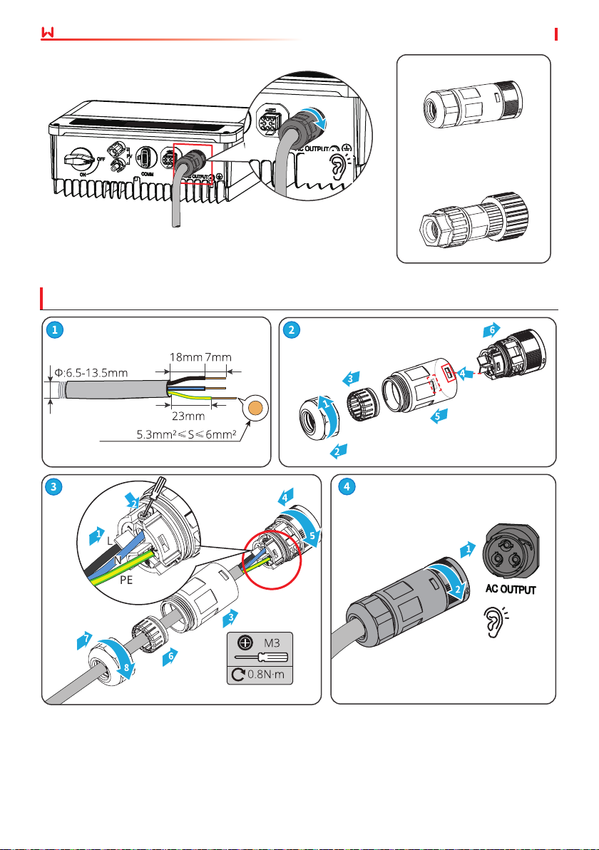
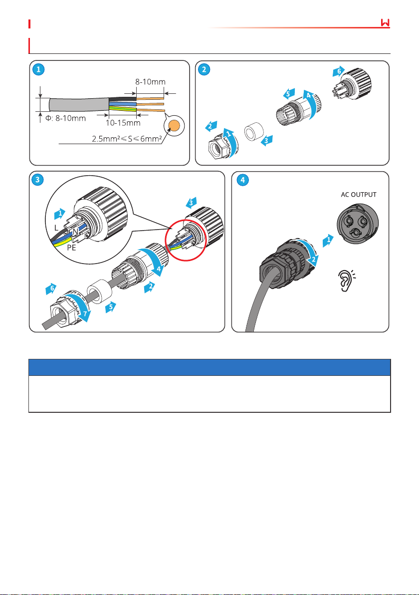
• Pay attention to the silkscreens L, N, PE on the AC terminal. Connect the AC cables to
the corresponding terminals. The inverter may be damaged if the cables are connected
inappropriately.
• Make sure that the whole cable cores are inserted into the AC terminal holes. No part of
the cable core can be exposed.
• Make sure that the cables are connected securely. Otherwise, the terminal may be too hot
to damage the inverter when the inverter is working.
Step 1 Make the AC output cable.
Step 2 Disassemble the DC routing hole’s end cap.
Step 3 Use the cable gland for routing wires.
Step 4 Plut the AC connector into the inverter.
21
Page 26
AC Connector-1
Copper,
Click
User Manual V1.3-2023-05-1506 Electrical Connection
AC Connector-1
or
AC Connector-2
22
Click
Page 27
User Manual V1.3-2023-05-15 06 Electrical Connection
AC Connector-2
Copper,
Click
NOTICE
• Make sure that the cable is connected correctly and securely. Clear the debris after completing
the connection.
• Seal the AC output terminal to ensure the ingress protection rating.
23
Page 28
User Manual V1.3-2023-05-1506 Electrical Connection
6.5 Communication
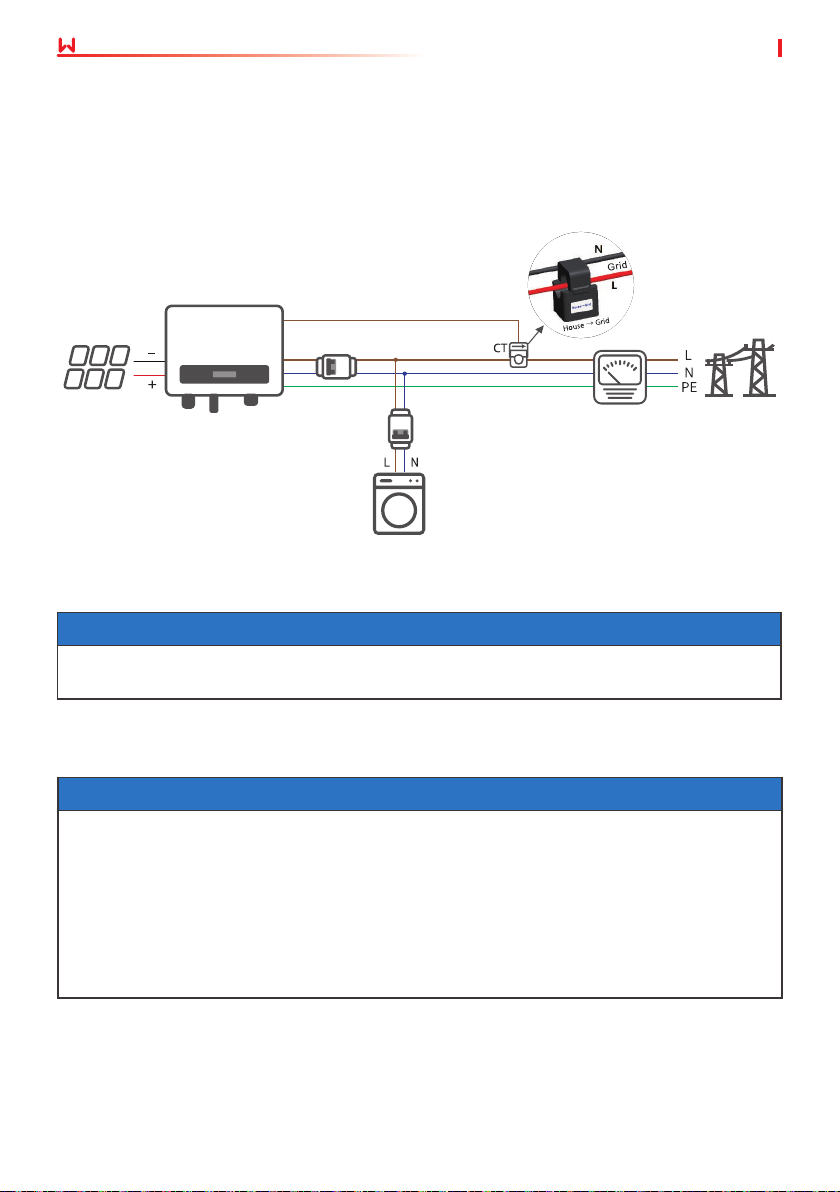
6.5.1 Communication Network Introduction
Power Limit Network
The PV station generates power for self-consumption, but the electric equipment cannot
consume all the generated power. The inverter can monitor the on-grid electric data in real-time
and adjust the output power to avoid the residual current feeding back to the utility grid.
CT90
Inverter
Breaker
Loads
Circuit
Meter
Utility Grid
PV String
Circuit
Breaker
Notice
After completing cable connections, set related parameters via LCD or SolarGo app to enable
export power limit control or output power limit control.
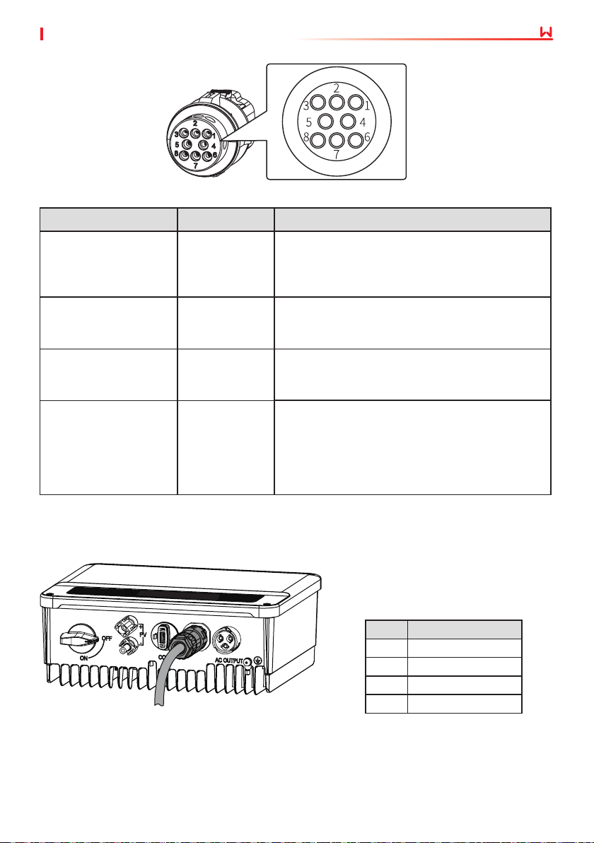
6.5.2 Connecting the Communication Cable (optional)
NOTICE
• DRED (Demand response enabling device) is only for Australian and New Zealand
installations, incompliance with Australian and New Zealand safety requirements.
• Contat the after-sales service to get the DRED terminal if you need to use DRED function.
• DRED function is o by default. Start this function via SolarGo App if it's needed.
• Remote shutdown is only for Europe installations, in compliance with European safety
requirements. And Remote shutdown device is not provided by GOODWE.
• Remote shutdown function is o by default. Start this function via SolarGo App if it's
needed.
24
Page 29
User Manual V1.3-2023-05-15 06 Electrical Connection
Communication Type Denition Function
3: RS485-
RS485
6: RS485+
7: RS485-
Used to connect multi inverters or the RS485 port
on the data logger.
8: RS485+
The port is reserved in compliance with grid
regulations in Europe. Related devices should be
prepared by customers.
Realize the anti-backfeed function by connecting
the meter and the CT. Contact the manufacturer
to purchase the devices if you need them.
The port is reserved in compliance to grid
regulations in Australia and New Zealand. Related
devices should be prepared by customers.
Remote shutdown
CT
DRED
4: Content +
5: Content -
1: CT-
2: CT+
3: DRM1/5
4: DRM2/6
5: DRM3/7
6: DRM4/8
7: REFGEN
8: COM/DRM0
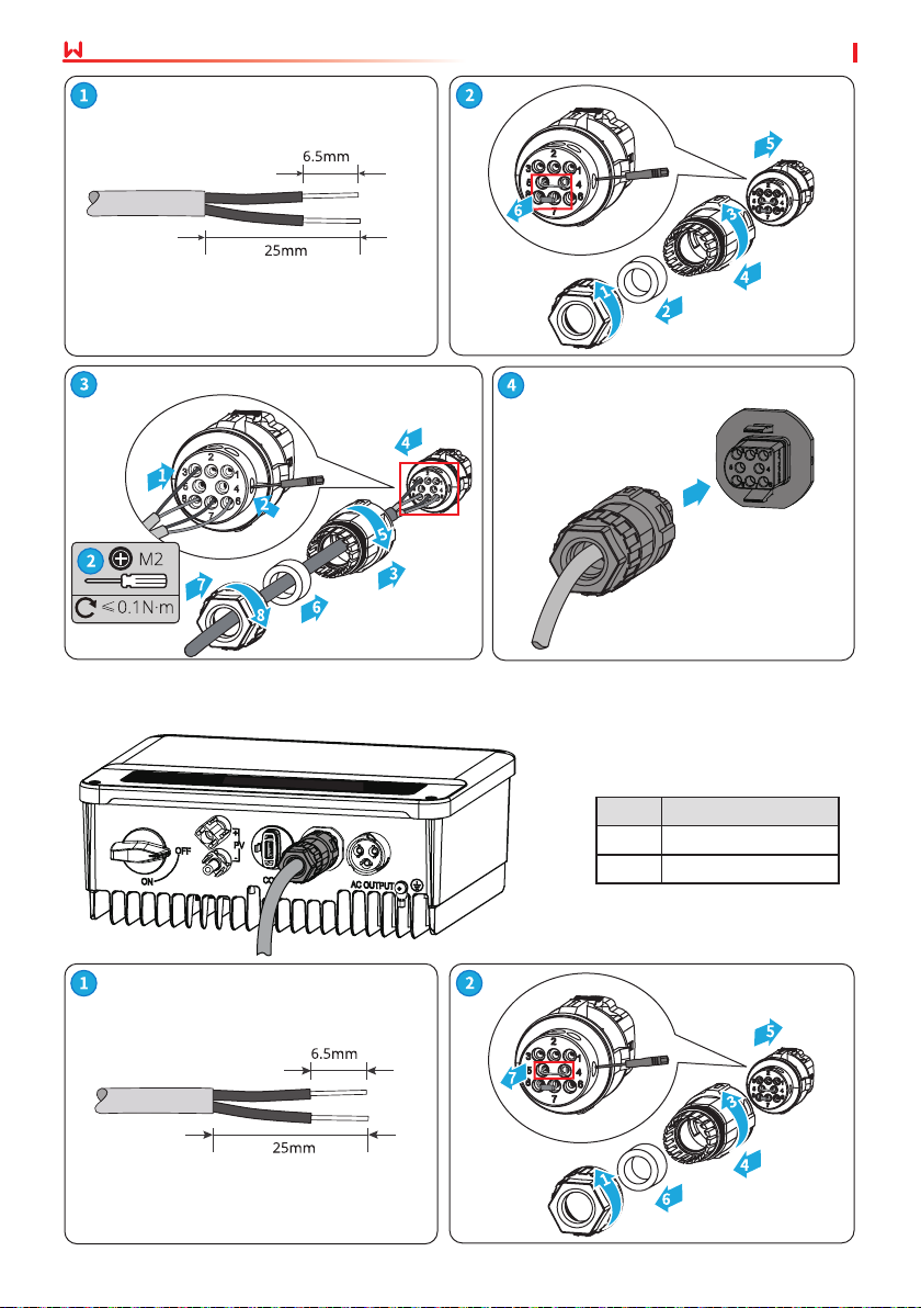
6.5.3 Connecting the RS485 Cable
25
No.
3 RS485-
6 RS485+
7 RS485-
8 RS485+
Function
Page 30
User Manual V1.3-2023-05-1506 Electrical Connection
6.5.4 Connecting the Remote Shutdown Cable
26
No.
4 Content +
5 Content -
Function
Page 31
User Manual V1.3-2023-05-15 06 Electrical Connection
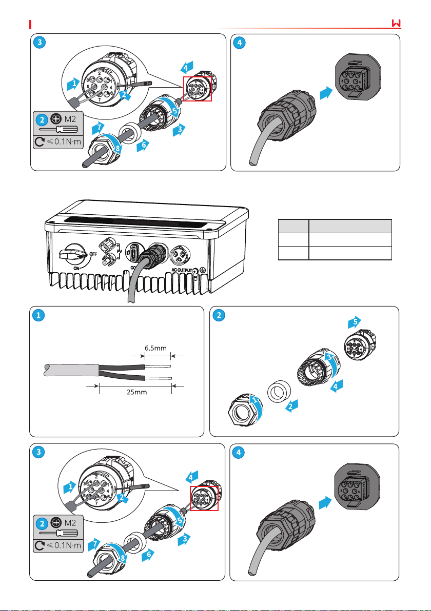
6.5.5 Connecting the CT Cable
No.
1 CT-
2 CT+
Function
27
Page 32
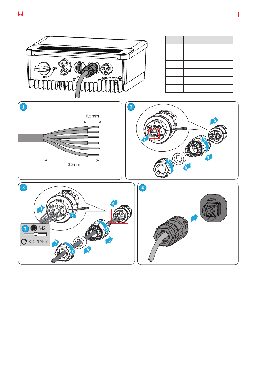
6.5.6 Connecting the DRED Cable
User Manual V1.3-2023-05-1506 Electrical Connection
No.
3 DRM1/5
4 DRM2/6
5 DRM3/7
6 DRM4/8
7 REFGEN
8 COM/DRM0
Function
28
Page 33
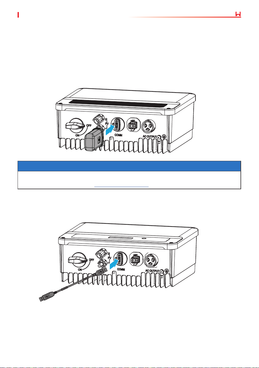
User Manual V1.3-2023-05-15 06 Electrical Connection
6.5.7 Installing the Communication Module (optional)
Plug a communication module into the inverter to establish a connection between the inverter
and the smartphone or web pages. The communication module can be a Bluetooth module,
WiFi module, LAN module, GPRS moduel, or 4G module. Set inverter parameters, check running
information and fault information, and observe system status in time via the smartphone or web
pages.
WiFi kit, LAN kit, 4G kit, GPRS, Bluetooth Kit, Wi-Fi/LAN Kit module: optional.
NOTICE
Refer to the delivered WiFi module user manual to get more introduction to the module. For
more detailed information, visit https://en.goodwe.com.
6.5.8 Connecting the USB-RS485 Cable
USB-RS485 cable: Only for Brazil.
29
Page 34
07 Equipment Commissioning
User Manual V1.3-2023-05-15
7 Equipment Commissioning
7.1 Check Before Power ON
No. Check Item
The product is rmly installed at a clean place that is well-ventilated and easy to
1
operate.
The PE, DC input, AC output, and communication cables are connected correctly and
2
securely.
3 Cable ties are intact, routed properly and evenly.
4 Unused ports and terminals are sealed.
The voltage and frequency at the connection point meet the inverter grid connection
5
requirements.
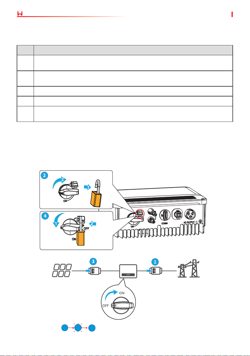
7.2 Power On
Step 1 Turn on the AC switch between the inverter and the utility grid.
Step 2 (optional) Turn on the DC switch between the inverter and the PV string.
Step 3 Turn on the DC switch of the inverter.
For Australia only.
Turn on
PV
1 3 2
DC Isolator
(Optional)
Inverter
30
AC Breaker
Grid
Page 35
User Manual V1.3-2023-05-15
08 System Commissioning
8 System Commissioning
8.1 Indicators and Buttons
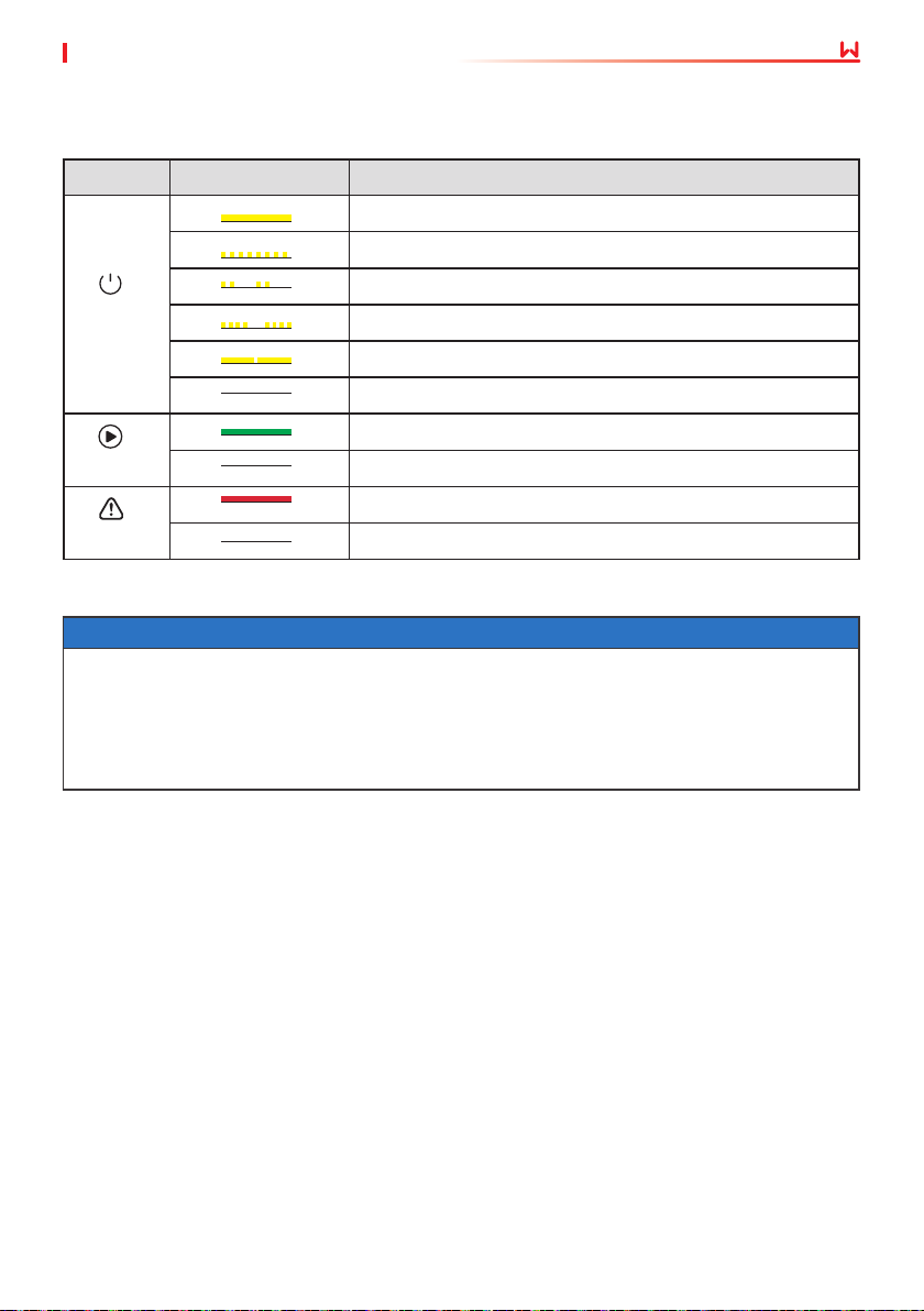
Indicator Status Description
ON = WiFi is connected/active.
BLINK 1 = WiFi system is resetting.
Power
Operating
Faulty
8.2 Setting Inverter Parameters via LCD
• Inverter software version shown in this document is V1.00.00.13. The screenshots are for
reference only. The actual interface may dier.
• The name, range, and default value of the parameters are subject to change or adjustment.
The actual display prevails.
• To prevent the generating capacity from being inuenced by wrong parameters, the power
parameters should be set by professionals.
BLINK 2 = WiFi not connect to the router.
BLINK 4 = WiFi server problem.
BLINK = RS485 is connected.
OFF = WiFi is not active.
ON = The inverter is feeding power.
OFF = The inverter is not feeding power at the moment.
ON = A fault has occurred.
OFF = No fault.
NOTICE
31
Page 36
08 System Commissioning
User Manual V1.3-2023-05-15
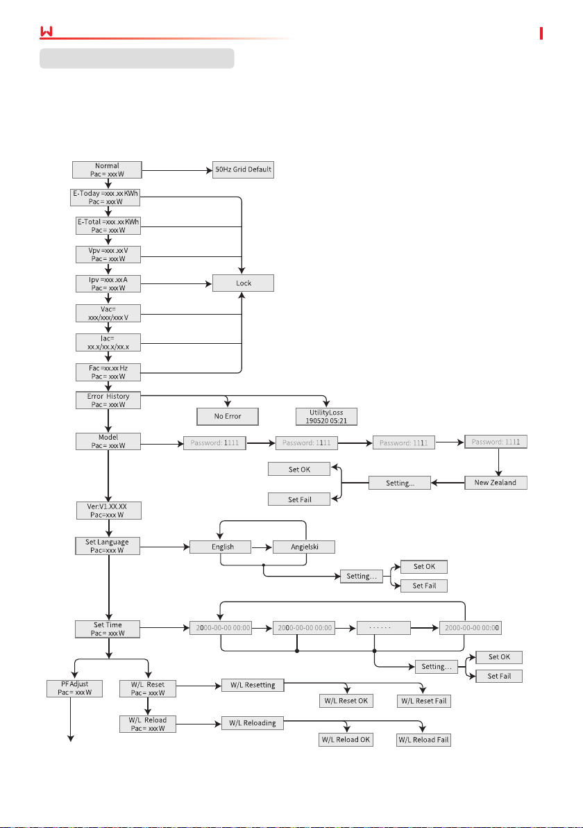
LCD Button Description
This part describes the menu structure, allowing you view inverter information and set
parameters more conveniently.
Main menu
Long press for 2s
Short press
Long press for 2s
Short press
Long press for 2s
Short press
Long press for 2s
Short press
Long press for 2s
Short press
Long press for 2s
Short press
Long press for 2s
Short press
Long press for 2s
Short press
Long press for 2s
Short press
Next page
Short press
Long press
Short press
Short press
Short press
Short press
for 2s
Short press to select 0~9
Initial Password: 1111
Long press
for 2s
Long press
for 2s
Long press
Long press
for 2s
for 2s
Long press
for 2s
Short press
Short press
Long press
for 2s
Short press to
select 0~9
Long press
Short press to select 0~9
Wait
Long press for 2s
Long press
for 2s
Short press to
select 0~9
Wait
Wait
32
for 2s
Short press to select 0~9
Long press
Short press and
wait for 10s
Long press
for 2s
for 2s
Short press to
select 0~9
wait for 10s
Short press to
select 0~9
Page 37
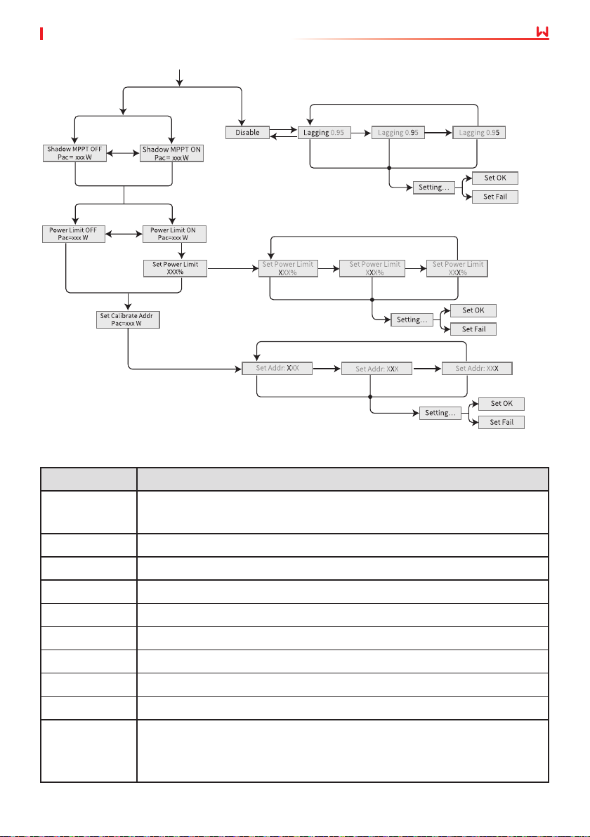
User Manual V1.3-2023-05-15
Previous page
Or
Short
press
Long press
for 2s
Or
Long press
for 2s
Short press
Short
press
Long press
Short press
Long press
for 2s
for 2s
Short press
Short press to
select 0~2
Long press
for 2s
Short press short press to
select"Leading"
or "Lagging"
Wait
Long press for 2s
Long press
for 2s
Wait
08 System Commissioning
Long press for 2s
Long press
for 2s
Short press to
select 8~9
Wait
Long press
for 2s
Short press to
select 0~9
Short press to
select 0~9
Short press to
select 0~9
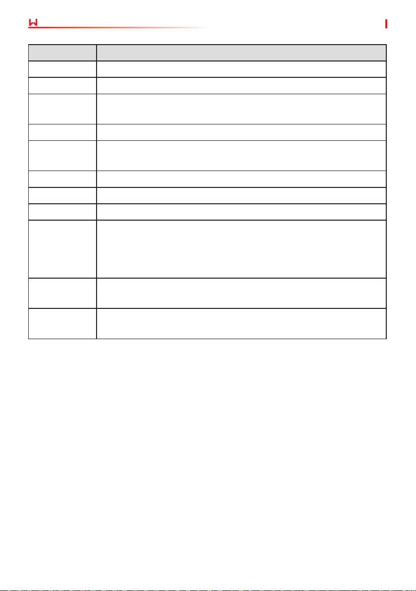
8.2.1 Inverter Parameter Introduction
Parameters Description
Normal
Home page. Indicates the real-time power of the inverter. Long press for 2s
to check the current safety code.
E-Today Check the generated power of the system for that day.
E-Total Check the total generated power of the system.
Vpv Check the DC input voltage of the inverter.
Ipv Check the DC input current of the inverter.
Vac Check the voltage of the utility grid.
Iac Check the AC output current of the inverter.
Fac Check the frequency of the utility grid.
Error History Check historical error message records of the inverter.
Indicates the specic inverter model. Long press for 2s to set the safety
Model
code. Set the safety country in compliance with the local grid standards and
application scenario of the inverter.
33
Page 38
08 System Commissioning
Parameters Description
Ver Check the software version.
Set Language Set language accordingly. Languages: English, Portuguese, Spanish.
Set Time
W/L Reset Power o and restart the WiFi module.
W/L Reload
PF Adjust Set the power factor of the inverter according to actual situation.
Time Interval Set Time Interval according to actual needs.
Shadow MPPT Enable the shadow scan function if the PV panels are shadowed.
Power Limit
Set Power Limit
Set Calibrate
Addr
Set time according to the actual time in the country/region where the
inverter is located.
Restore the factory settings of the WiFi module. Recongure the WiFi
module network parameters after restoring the factory settings,
Soft limit: Set the power feed into the utility grid according to local
requirements and standards.
Hard limit: The inverter and the utility grid will automatically disconnect
when the power feeds into the grid excesses the required limit.
Set the power feed back into the utility grid according to the actual
situation.
Set the actual Modbus address.
User Manual V1.3-2023-05-15
34
Page 39
User Manual V1.3-2023-05-15
08 System Commissioning
8.3 Upgrading the Firmware Via USB Flash Disk
Step 1 Contact the after-sales service to obtain the upgrade package.
Step 2 Save the upgrade package in the USB ash drive.
Step 3 Insert the USB ash drive into the USB port, and upgrade the software version of the
inverter following the prompts.
8.4 Setting Inverter Parameters via SolarGo App
SolarGo app is a mobile application that communicates with the inverter via Bluetooth module,
WIFi module or GPRS module. Commonly used functions are as follows:
1. Check the operating data, software version, alarms, etc.
2. Set grid parameters, communication parameters, etc.
3. Equipment maintenance.
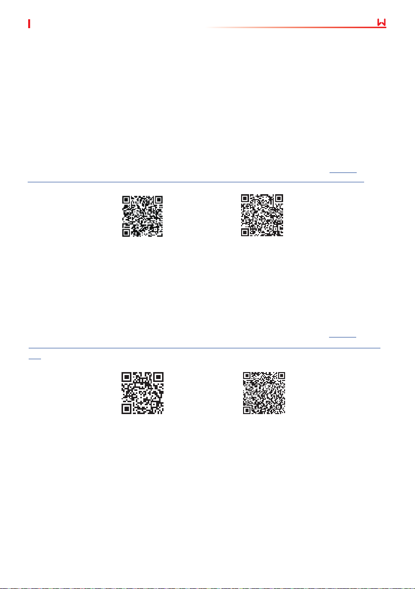
For more details, refer to the SolarGo APP User Manual. Scan the QR code or visit https://
en.goodwe.com/Ftp/EN/Downloads/User%20Manual/GW_SolarGo_User%20Manual-EN.pdf to
get the user manual.
SolarGo App
SolarGo App User
Manual
8.5 Monitoring via SEMS Portal
SEMS Portal is an monitoring platform used to manage organizations/users, add plants, and
monitor plant status.
For more details, refer to the SEMS Portal User Manual. Scan the QR code or visit https://
en.goodwe.com/Ftp/EN/Downloads/User%20Manual/GW_SEMS%20Portal-User%20Manual-EN.
pdf to get the user manual.
SEMS Portal
SEMS Portal User
Manual
35
Page 40
09 Maintenance
User Manual V1.3-2023-05-15
9 Maintenance
9.1 Power O the Inverter
DANGER
• Power o the inverter before operations and maintenance. Otherwise, the inverter may be
damaged or electric shocks may occur.
• Delayed discharge. Wait until the components are discharged after power o.
Step 1 (Optional) Send shutdown command to the inverter.
Step 2 Turn o the AC switch between the inverter and the utility grid.
Step 3 Turn o the DC switch of the inverter.
9.2 Removing the Inverter
WARNING
• Make sure that the inverter is powered o.
• Wear proper PPE before any operations.
Step 1 Disconnect all the cables, including DC cables, AC cables, communication cables, the
communication module, and PE cables.
Step 2 Grab the handles or hoist the inveter to remove the inverter from the mounting plate.
Step 3 Remove the mounting plate.
Step 4 Store the inverter properly. If the inverter needs to be used later, ensure that the storage
conditions meet the requirements.
9.3 Disposing of the Inverter
If the inverter cannot work anymore, dispose of it according to the local disposal
requirements for electrical equipment waste. The inverter cannot be disposed of together
with household waste.
9.4 Troubleshooting
Perform troubleshooting according to the following methods. Contact the after-sales service if
these methods do not work.
Collect the information below before contacting the after-sales service, so that the problems can
be solved quickly.
1. Inverter information like serial number, software version, installation date, fault time, fault
frequency, etc.
2. Installation environment, including weather conditions, whether the PV modules are
sheltered or shadowed, etc. It is recommended to provide some photos and videos to assist
in analyzing the problem.
3. Utility grid situation.
36
Page 41
User Manual V1.3-2023-05-15
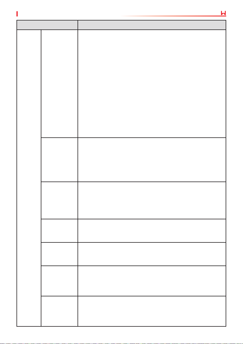
Type of fault Troubleshooting
1. Disconnect DC switch, take o DC connector, check the
impedance between PV (+) & PV(-) to earth.
2. If impedance is less than 100 kΩ, please check the insulation of
PV string wiring to earth.
3. If impedance is large than 100 kΩ, please contact local service
oce.
Isolation
Failure
Ground I
Failure
Inverter
Failure
Vac Failure
Fac Failure
Utility Loss
PV Over
Voltage
Over
Temperature
4. Take o AC connector, measure the impedance between
neutral.
Inverters for the Australian and New Zealand markets can also be
alerted in the following ways in the event of insulation impedance
failure:
1. The inverter is equipped with the buzzer: the buzzer sounds
continuously for 1 minute in case of failure; If the fault is not
resolved, the buzzer sounds every 30 minutes.
2. Add the inverter to the monitoring platform, and set the alarm
reminder, the alarm information can be sent to the customer
by emails.
1. The ground current is too high.
2. Unplug the inputs from the PV generator and check the
peripheral AC system.
3. When the problem is cleared, reconnect the PV panel and check
the Inverter status.
4. Contact local service oce for help if the problem still persist.
1. The PV Inverter will automatically restart within 5 minutes if the
grid returns to normal.
2. Make sure grid voltage conforms with the specication.
3. Make sure neutral (N) wire and PE wire are connected well.
4. Contact local service oce for help if the problem still persist.
1. Grid is not connected.
2. Check grid connection cables.
3. Check availability of grid.
1. Not connect to the grid.
2. Check if the power grid is connected to cable.
3. Check the availability of power grid.
1. Check if the PV open circuit voltage is higher or too close to the
maximum input voltage or not.
2. If the problem still persist when PV voltage is less than the
maximum input voltage, contact local service oce for help.
1. The internal temperature is higher than normal value specied.
2. Reduce ambient temperature.
3. Move the inverter to a cool place.
4. If the problem still exists, contact local service oce for help.
09 Maintenance
37
Page 42
09 Maintenance
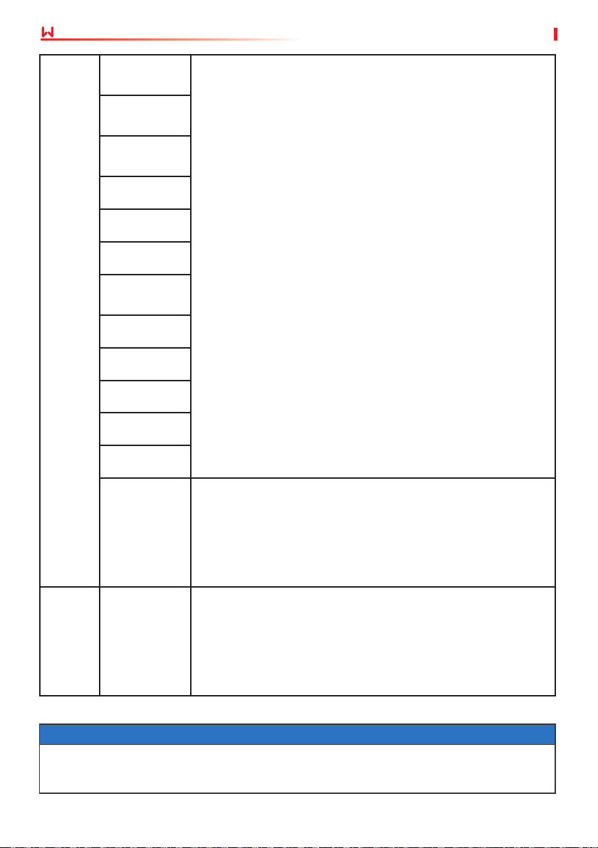
Inverter
Failure
Relay-Check
Failure
DCI Injection
High
EEPROM R/W
Failure
SCI Failure
SPI Failure
DC BUS High
BUS
Unbalance
GFCI Failure
Ifan Fault
Efan Fault
Afan Fault
User Manual V1.3-2023-05-15
1. Turn o DC switch of the inverter.
2. Wait till the inverter's LCD light is o.
3. Turn on DC switch and make sure it is connected.
4. If the problem still exists, contact local service oce for help.
AFCI Fail
1. Turn o DC switch, take o DC connector, measure the voltage
of PV array.
No display
Wi-Fi module
Others
When sunlight is insucient, the PV inverter may continuously start up and shut down
automatically due to insucient power generation from the PV panels, which would not lead
to inverter damage.
fail to
connect to
network
2. Plug in DC connector, and turn on DC switch.
3. If PV array voltage is lower than 250V , please check
conguration of inverter module.
4. If voltage is higher than 250V , please contact local oce.
1. If the Wi-Fi module fail to connect to network after choosing
the right router hotspot and entering the right passwords, it's
possible that there are special characters not supported by
module in the hotspot passwords. Please modify the password to
consist of only Arabic numerals or uppercase / lowercase letters.
2. If the problem still exists, contact local service oce for help.
NOTICE
38
Page 43
User Manual V1.3-2023-05-15
09 Maintenance
9.5 Routine Maintenance
WARNING
• Make sure that the inverter is powered o.
• Wear proper PPE before any operations.
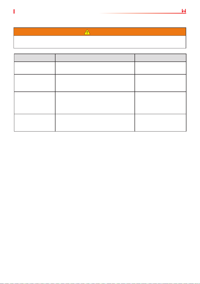
Maintaining Item Maintaining Method Maintaining Period
System Clean
DC Switch
Electrical Connection
Sealing
Check the heat sink, air intake, and air
outlet for foreign matter or dust.
Turn the DC switch on and o ten
consecutive times to make sure that it is
working properly.
Check whether the cables are securely
connected. Check whether the cables are
broken or whether there is any exposed
copper core.
Check whether all the terminals and ports
are properly sealed. Reseal the cable hole
if it is not sealed or too big.
Once 6-12 months
Once a year
Once 6-12 months
Once a year
39
Page 44
10 Technical Parameters
User Manual V1.3-2023-05-15
10 Technical Parameters
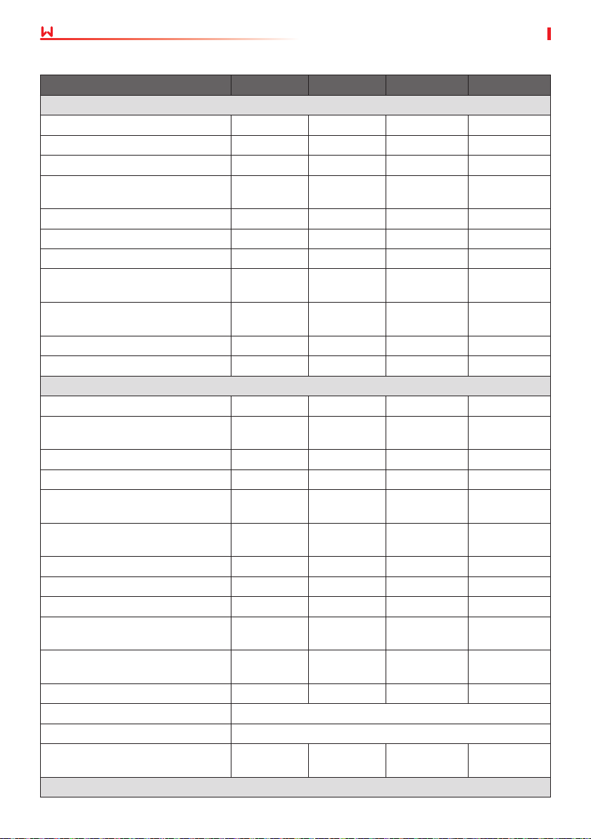
Technical Data GW700-XS GW1000-XS GW1500-XS GW2000-XS
Input
Max. Input Power (W)
*1
Max. Input Voltage (V) 500 500 500 500
MPPT Operating Voltage Range (V) 40~450 40~450 50~450 50~450
MPPT Voltage Range at Nominal
Power (V)
Start-up Voltage (V) 40 40 50 50
Nominal Input Voltage (V) 360 360 360 360
Max. Input Current per MPPT (A) 12.5 12.5 12.5 12.5
Max. Short Circuit Current per
MPPT (A)
Max. Backfeed Current to The
Array (A)
Number of MPP Trackers 1 1 1 1
Number of Strings per MPPT 1 1 1 1
Output
Nominal Output Power (W) 700 1,000 1,500 2,000
Nominal Output Apparent Power
(VA)
Max. AC Active Power (W)
Max. AC Apparent Power (VA)
*2
*2
Nominal Power at 40℃ (W)(Only
for Brazil)
Max Power at 40℃ (Including AC
Overload) (W)(Only for Brazil)
Nominal Output Voltage (V) 230 230 230 230
Nominal AC Grid Frequency (Hz) 50/60 50/60 50/60 50/60
Max. Output Current (A) 3.5 4.8 7.2 9.6
Max. Output Fault Current (Peak
and Duration) (A/ms)
Inrush Current (Peak and
Duration) (A/us)
Nominal Output Current (A) 3.0 4.3 6.5 8.7
Power Factor ~1 (Adjustable from 0.8 leading to 0.8 lagging)
Max. Total Harmonic Distortion <3%
Maximum Output Overcurrent
Protection (A)
Eciency
910 1,300 1,950 2,600
80~450 85~450 125~450 165~450
15.6 15.6 15.6 15.6
0 0 0 0
700 1,000 1,500 2,000
800 1,100 1,650 2,200
800 1,100 1,650 2,200
700 1,000 1,500 2,000
800 1,100 1,650 2,200
25@5ms 25@5ms 25@5ms 25@5ms
50@2us 50@2us 50@2us 50@2us
24 24 24 24
40
Page 45
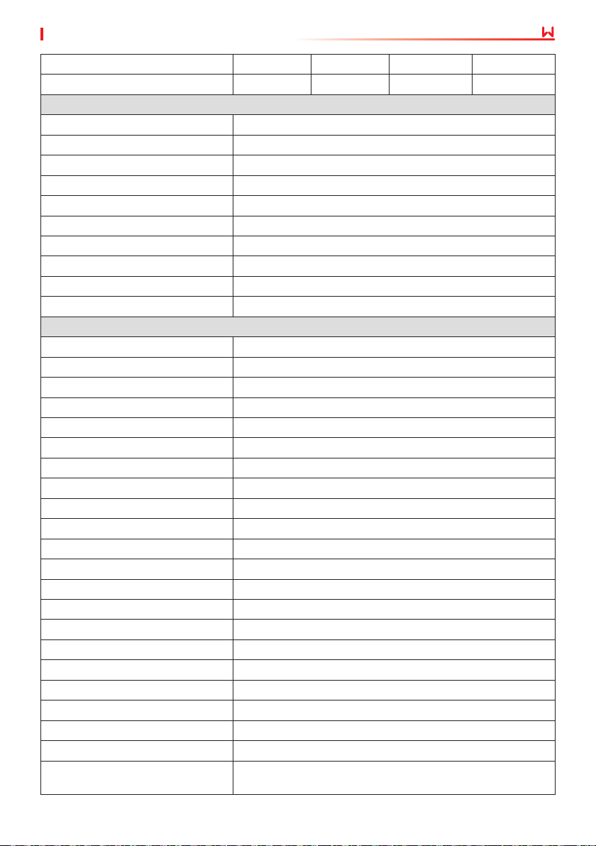
User Manual V1.3-2023-05-15
10 Technical Parameters
Max. Eciency 97.2% 97.2% 97.3% 97.5%
European Eciency 96.0% 96.4% 96.6% 97.0%
Protection
PV Insulation Resistance Detection Integrated
Residual Current Monitoring Integrated
PV Reverse Polarity Protection Integrated
Anti-islanding Protection Integrated
AC Overcurrent Protection Integrated
AC Short Circuit Protection Integrated
AC Overvoltage Protection Integrated
DC Switch Integrated
DC Surge Protection Type III
AC Surge Protection Type III
General Data
Operating Temperature Range (℃) -25~+60
Relative Humidity 0~100%
Max. Operating Altitude (m)
*3
4000
Cooling Method Natural Convection
User Interface LED, LCD (Optional), WLAN+APP
Communication WiFi, LAN or RS485(Optional)
Communication Protocols Modbus-RTU (SunSpec Compliant)
Weight (kg) 5.8
Dimension (W×H×D mm) 295×230×113
Noise Emission (dB) <25
Topology Non-isolated
Self-consumption at Night (W) <1
Ingress Protection Rating IP65
DC Connector MC4 (2.5-4mm²)
AC Connector Plug and Play Connector
Environmental Category 4K4H
Pollution Degree III
Overvoltage Category DC II / AC III
Protective Class I
The Decisive Voltage Class (DVC) PV: C AC: C Com: A
Active Anti-islanding Method AFDPF + AQDPF
Country of Manufacture (Only for
Australia)
China
*4
41
Page 46
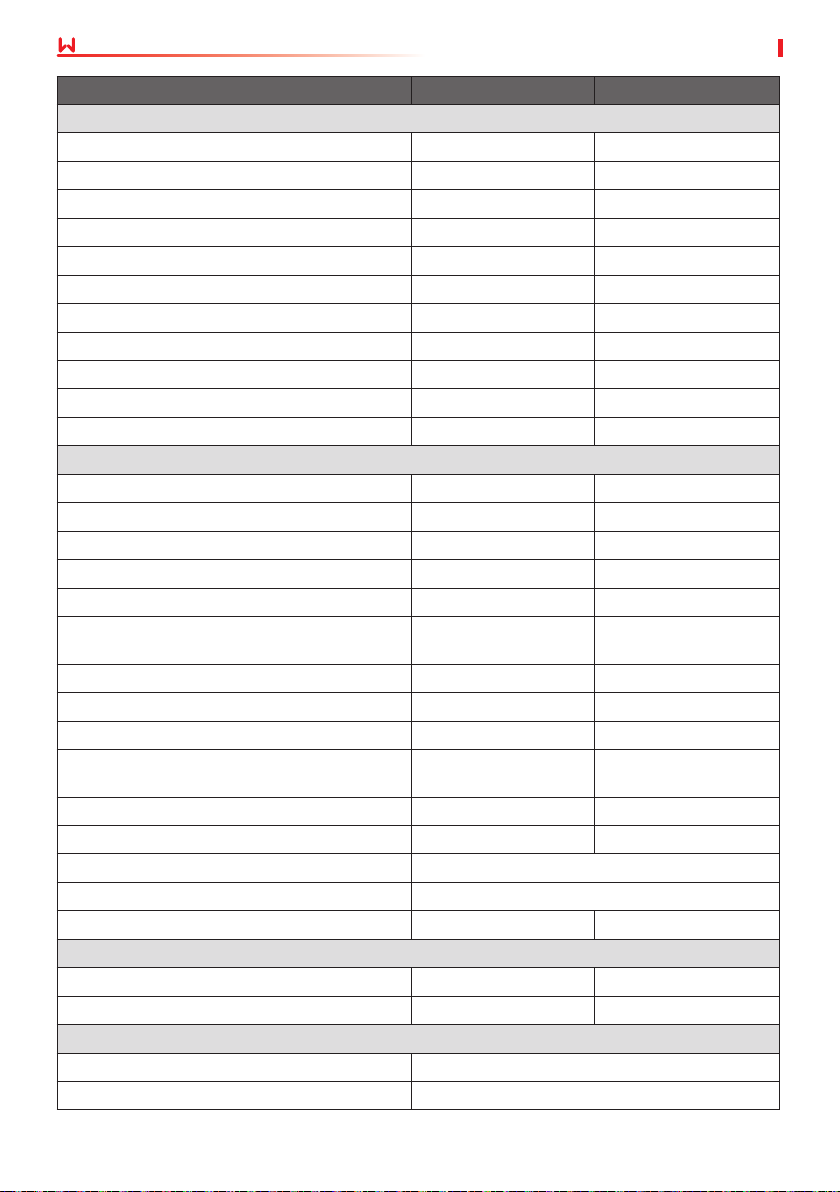
10 Technical Parameters
User Manual V1.3-2023-05-15
Technical Data GW2500-XS GW3000-XS
Input
Max. Input Power (W)
*1
3,250 3,900
Max. Input Voltage (V) 500 500
MPPT Operating Voltage Range (V) 50-450 50-450
MPPT Voltage Range at Nominal Power (V) 240-450 280-450
Start-up Voltage (V) 50 50
Nominal Input Voltage (V) 360 360
Max. Input Current per MPPT (A) 12.5 12.5
Max. Short Circuit Current per MPPT (A) 15.6 15.6
Max. Backfeed Current to The Array (A) 0 0
Number of MPP Trackers 1 1
Number of Strings per MPPT 1 1
Output
Nominal Output Power (W) 2,500 3,000
Nominal Output Apparent Power (VA) 2,500 3,000
Max. AC Active Power (W)
*2
Max. AC Apparent Power (VA)
*2
2,750 3,300
2,750 3,300
Nominal Power at 40℃ (W)(Only for Brazil) 2,500 3,000
Max Power at 40℃ (Including AC Overload)
(W)(Only for Brazil)
2,750 3,300
Nominal Output Voltage (V) 230 230
Nominal AC Grid Frequency (Hz) 50/60 50/60
Max. Output Current (A) 12.0 14.3
Max. Output Fault Current (Peak and
Duration) (A/ms)
30@5ms 30@5ms
Inrush Current (Peak and Duration) (A/us) 50@2us 50@2us
Nominal Output Current (A) 10.9 13.0
Power Factor ~1 (Adjustable from 0.8 leading to 0.8 lagging)
Max. Total Harmonic Distortion <3%
Maximum Output Overcurrent Protection (A) 32 32
Eciency
Max. Eciency 97.6% 97.6%
European Eciency 97.2% 97.2%
Protection
PV Insulation Resistance Detection Integrated
Residual Current Monitoring Integrated
42
Page 47
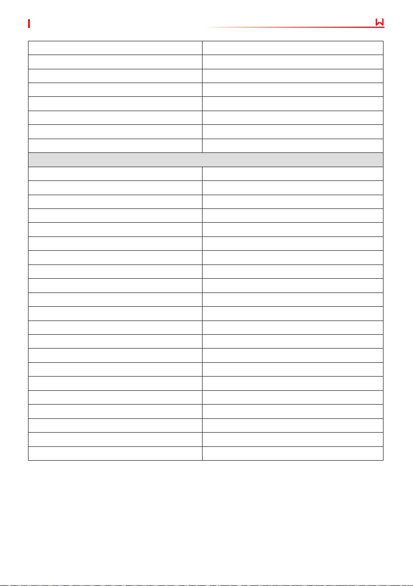
User Manual V1.3-2023-05-15
10 Technical Parameters
PV Reverse Polarity Protection Integrated
Anti-islanding Protection Integrated
AC Overcurrent Protection Integrated
AC Short Circuit Protection Integrated
AC Overvoltage Protection Integrated
DC Switch Integrated
DC Surge Protection Type III
AC Surge Protection Type III
General Data
Operating Temperature Range (℃) -25~+60
Relative Humidity 0~100%
Max. Operating Altitude (m)
*3
4000
Cooling Method Natural Convection
User Interface LED, LCD (Optional), WLAN+APP
Communication WiFi, LAN or RS485(Optional)
Weight (kg) 5.8
Dimension (W×H×D mm) 295×230×113
Noise Emission (dB) <42
Topology Non-isolated
Self-consumption at Night (W) <1
Ingress Protection Rating IP65
DC Connector MC4 (2.5-4mm²)
AC Connector Plug and Play Connector
Environmental Category 4K4H
Pollution Degree III
Overvoltage Category DC II / AC III
Protective Class I
The Decisive Voltage Class (DVC) PV: C AC: C Com: A
Active Anti-islanding Method AFDPF + AQDPF
*4
Country of Manufacture (Only for Australia) China
43
Page 48
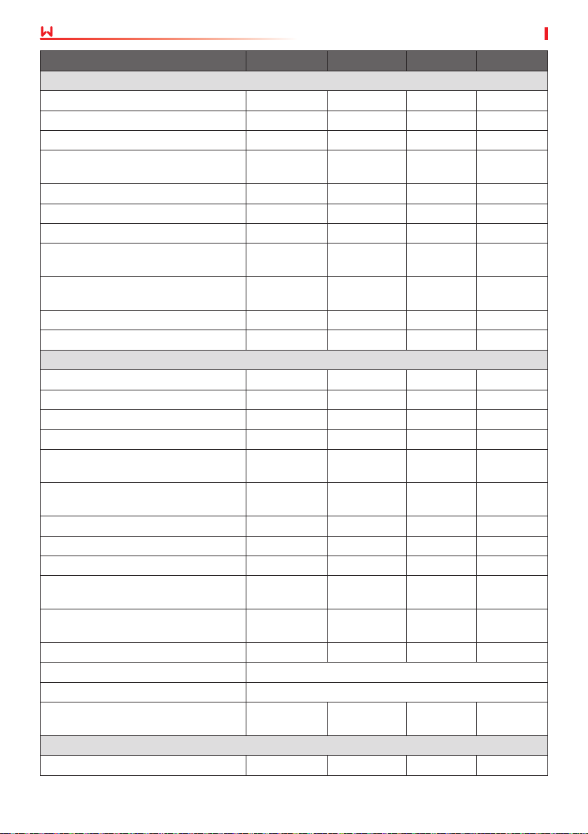
10 Technical Parameters
User Manual V1.3-2023-05-15
Technical Data GW2500N-XS GW3000N-XS GW3KB-XS GW3300-XS
Input
Max. Input Power (W)
*1
3,250 3,900 3,900 3,900
Max. Input Voltage (V) 600 600 600 500
MPPT Operating Voltage Range (V) 50-550 50-550 50-550 50-450
MPPT Voltage Range at Nominal
Power (V)
205-450 245-450 240-450 275-450
Start-up Voltage (V) 50 50 50 50
Nominal Input Voltage (V) 360 360 360 360
Max. Input Current per MPPT (A) 13.0 13.0 13.0 12.5
Max. Short Circuit Current per MPPT
(A)
Max. Backfeed Current to The Array
(A)
16.3 16.3 16.3 15.6
0 0 0 0
Number of MPP Trackers 1 1 1 1
Number of Strings per MPPT 1 1 1 1
Output
Nominal Output Power (W) 2,500 3,000 3,000 3,300
Nominal Output Apparent Power (VA) 2,500 3,000 3,000 3,300
Max. AC Active Power (W)
Max. AC Apparent Power (VA)
*2
*2
Nominal Power at 40℃ (W)(Only for
Brazil)
Max Power at 40℃ (Including AC
Overload) (W)(Only for Brazil)
2,750 3,300 3,300 3,300
2,750 3,300 3,300 3,300
2,500 3,000 3,000 3,300
2,750 3,300 3,300 3,300
Nominal Output Voltage (V) 220/230 220/230 220 230
Nominal AC Grid Frequency (Hz) 50/60 50/60 60 50/60
Max. Output Current (A) 12.0 14.3 14.3 14.3
Max. Output Fault Current (Peak and
Duration) (A/ms)
Inrush Current (Peak and Duration)
(A/us)
30@5ms 30@5ms 30@5ms 30@5ms
50@2us 50@2us 50@2us 50@2us
Nominal Output Current (A) 11.4/10.9 13.6/13.0 13.6/13.0 14.3
Power Factor ~1 (Adjustable from 0.8 leading to 0.8 lagging)
Max. Total Harmonic Distortion <3%
Maximum Output Overcurrent
Protection (A)
32 32 32 32
Eciency
Max. Eciency 97.6% 97.6% 97.6% 97.6%
44
Page 49
User Manual V1.3-2023-05-15
11 Appendix
European Eciency 97.2% 97.2% 97.2% 97.2%
Protection
PV Insulation Resistance Detection Integrated
Residual Current Monitoring Integrated
PV Reverse Polarity Protection Integrated
Anti-islanding Protection Integrated
AC Overcurrent Protection Integrated
AC Short Circuit Protection Integrated
AC Overvoltage Protection Integrated
DC Switch Integrated
DC Surge Protection Type III (Type II Optional) Type III
AC Surge Protection Type III
AFCI Optional
General Data
Operating Temperature Range (℃) -25~+60
Relative Humidity 0~100%
Max. Operating Altitude (m)
*3
4000
Cooling Method Natural Convection
User Interface LED, LCD (Optional), WLAN+APP
Communication WiFi, LAN or RS485(Optional)
Weight (kg) 5.8
Dimension (W×H×D mm) 295×230×113
Noise Emission (dB) <42
Topology Non-isolated
Self-consumption at Night (W) <1
Ingress Protection Rating IP65
DC Connector MC4 (2.5-4mm²)
AC Connector Plug and Play Connector
Environmental Category 4K4H
Pollution Degree III
Overvoltage Category DC II / AC III
Protective Class I
The Decisive Voltage Class (DVC) PV: C AC: C Com: A
Active Anti-islanding Method AFDPF + AQDPF
Country of Manufacture (Only for
Australia)
China
*4
45
Page 50
11 Appendix
User Manual V1.3-2023-05-15
Technical Data GW700-XS-11 GW1000-XS-11 GW1500-XS-11 GW2000-XS-11
Input
Max. Input Power (W)
*1
910 1,300 1,950 2,600
Max. Input Voltage (V) 500 500 500 500
MPPT Operating Voltage
Range (V)
MPPT Voltage Range at
Nominal Power (V)
40~450 40~450 50~450 50~450
65~450 85~450 125~450 165~450
Start-up Voltage (V) 40 40 50 50
Nominal Input Voltage
(V)
Max. Input Current per
MPPT (A)
Max. Short Circuit
Current per MPPT (A)
Max. Backfeed Current
to The Array (A)
360 360 360 360
15 15 15 15
18.75 18.75 18.75 18.75
0 0 0 0
Number of MPP Trackers 1 1 1 1
Number of Strings per
MPPT
1 1 1 1
Output
Nominal Output Power
(W)
Nominal Output
Apparent Power (VA)
Max. AC Active Power
*2
(W)
Max. AC Apparent Power
*2
(VA)
Nominal Power at 40℃
(W)(Only for Brazil)
700 1,000 1,500 2,000
700 1,000 1,500 2,000
800 1,100 1,650 2,200
800 1,100 1,650 2,200
700 1,000 1,500 2,000
Max Power at 40℃
(Including AC Overload)
800 1,100 1,650 2,200
(W)(Only for Brazil)
Nominal Output Voltage
(V)
Output Voltage Range
(V)
Nominal AC Grid
Frequency (Hz)
AC Grid Frequency
Range (Hz)
220/230 220/230 220/230 220/230
154~288 154~288 154~288 154~288
50/60 50/60 50/60 50/60
45~55/57~63 45~55/57~63 45~55/57~63 45~55/57~63
Max. Output Current (A) 3.5 4.8 7.2 9.6
46
Page 51
User Manual V1.3-2023-05-15
Max. Output Fault
Current (Peak and
Duration) (A/ms)
Inrush Current (Peak
and Duration) (A/us)
Nominal Output Current
(A)
Power Factor ~1 (Adjustable from 0.8 leading to 0.8 lagging)
Max. Total Harmonic
Distortion
Maximum Output
Overcurrent Protection
(A)
Eciency
Max. Eciency 97.2% 97.2% 97.3% 97.5%
European Eciency 96.0% 96.4% 96.6% 97.0%
Protection
PV Insulation Resistance
Detection
Residual Current
Monitoring
Anti-islanding Protection Integrated
AC Overcurrent
Protection
AC Short Circuit
Protection
AC Overvoltage
Protection
DC Switch Integrated
DC Surge Protection Type III (Type II Optional)
AC Surge Protection Type III
AFCI Optional
Emergency Power O Optional
Remote Shutdown Optional
General Data
Operating Temperature
Range (℃)
Relative Humidity 0~100%
Max. Operating Altitude
*3
(m)
Cooling Method Natural Convection
25@5ms 25@5ms 25@5ms 25@5ms
50@2us 50@2us 50@2us 50@2us
3.0 4.3 6.5 8.7
<3%
22.3 22.3 22.3 22.3
Integrated
Integrated
Integrated
Integrated
Integrated
-25~+60
3000
11 Appendix
47
Page 52
11 Appendix
User Manual V1.3-2023-05-15
User Interface LED, LCD , WLAN+APP
Communication WiFi or LAN or RS485(Optional)
Weight (kg) 5.8
Dimension (W×H×D mm) 295×230×113
Noise Emission (dB) <25
Topology Non-isolated
Self-consumption at
Night (W)
Ingress Protection
Rating
<1
IP65
DC Connector MC4 (2.5-4mm²)
AC Connector plug and play connector
Environmental Category 4K4H
Pollution Degree III
Overvoltage Category DC II / AC III
Protective Class I
The Decisive Voltage
Class (DVC)
Active Anti-islanding
Method
Country of Manufacture
(Only for Australia)
PV: C AC: C Com: A
AFDPF + AQDPF
*4
China
Technical Data GW2500-XS-11 GW3000-XS-11 GW3000-XS-B11
Input
Max. Input Power (W)
*1
3,250 3,900 3,900
Max. Input Voltage (V) 600 600 600
MPPT Operating Voltage Range (V) 50~550 50~550 50~550
MPPT Voltage Range at Nominal
Power (V)
200~450 240~450 240~450
Start-up Voltage (V) 50 50 50
Nominal Input Voltage (V) 360 360 360
Max. Input Current per MPPT (A) 15 15 15
Max. Short Circuit Current per MPPT
(A)
Max. Backfeed Current to The Array
(A)
18.75 18.75 18.75
0 0 0
Number of MPP Trackers 1 1 1
48
Page 53
User Manual V1.3-2023-05-15
11 Appendix
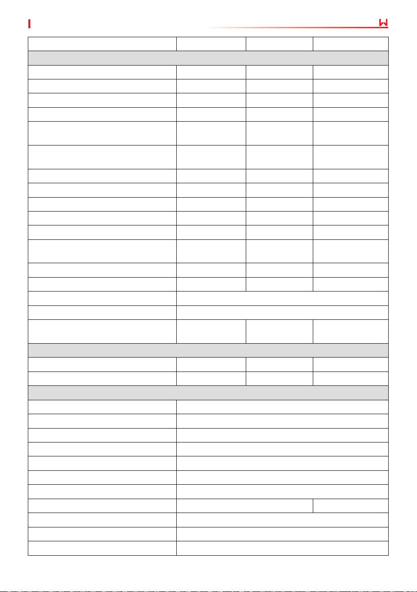
Number of Strings per MPPT 1 1 1
Output
Nominal Output Power (W) 2,500 3,000 3,000
Nominal Output Apparent Power (VA) 2,500 3,000 3,000
Max. AC Active Power (W)
Max. AC Apparent Power (VA)
*2
*2
Nominal Power at 40℃ (W)(Only for
Brazil)
Max Power at 40℃ (Including AC
Overload) (W)(Only for Brazil)
2,750 3,300 3,300
2,750 3,300 3,300
2,500 3,000 3,000
2,750 3,300 3,300
Nominal Output Voltage (V) 220/230 220/230 220
Output Voltage Range (V) 154~288 154~288 154~288
Nominal AC Grid Frequency (Hz) 50/60 50/60 60
AC Grid Frequency Range (Hz) 45~55/57~63 45~55/57~63 57~63
Max. Output Current (A) 12 14.3 14.3
Max. Output Fault Current (Peak and
Duration) (A)
25A@5ms 30A@5ms 30A@5ms
Inrush Current (Peak and Duration) (A) 50A@2us 50A@2us 50A@2us
Nominal Output Current (A) 11.4/10.9 13.6/13.0 13.6
Power Factor ~1 (Adjustable from 0.8 leading to 0.8 lagging)
Max. Total Harmonic Distortion <3%
Maximum Output Overcurrent
Protection (A)
31.5 31.5 31.5
Eciency
Max. Eciency 97.6% 97.6% 97.6%
European Eciency 97.2% 97.2% 97.2%
Protection
PV Insulation Resistance Detection Integrated
Residual Current Monitoring Integrated
Anti-islanding Protection Integrated
AC Overcurrent Protection Integrated
AC Short Circuit Protection Integrated
AC Overvoltage Protection Integrated
DC Switch Integrated
DC Surge Protection Type III (Type II Optional) Type III
AC Surge Protection Type III
AFCI Optional
Emergency Power O Optional
49
Page 54
11 Appendix
User Manual V1.3-2023-05-15
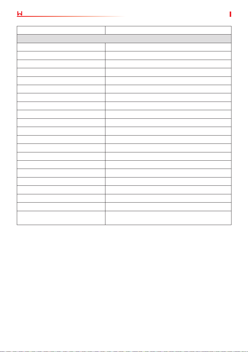
Remote Shutdown Optional
General Data
Operating Temperature Range (℃) -25~+60
Relative Humidity 0~100%
Max. Operating Altitude (m)
*3
3000
Cooling Method Natural Convection
User Interface LED, LCD , WLAN+APP
Communication WiFi or LAN or RS485(Optional)
Weight (kg) 5.8
Dimension (W×H×D mm) 295×230×113
Noise Emission (dB) <30
Topology Non-isolated
Self-consumption at Night (W) <1
Ingress Protection Rating IP65
DC Connector MC4 (2.5-4mm²)
AC Connector plug and play connector
Environmental Category 4K4H
Pollution Degree III
Overvoltage Category DC II / AC III
Protective Class I
The Decisive Voltage Class (DVC) PV: C AC: C Com: A
Active Anti-islanding Method AFDPF + AQDPF
Country of Manufacture (Only for
Australia)
China
*4
*1: For Australia Max. Input Power (W), GW700-XS-11 is 945, GW1000-XS-11 is 1350, GW1500-
XS-11 is 2025, GW2000-XS-11 is 2700, GW2500-XS-11 is 3375 , GW3000-XS-11 is 4050.
*2: For Chile Max. AC Active Power (W) & Max.Output Apparent Power(VA) : GW700-XS-11 is 700,
GW1000-XS-11 is 1000, GW1500-XS-11 is 1500, GW2000-XS-11 is 2000, GW2500-XS-11 is 2500,
GW3000-XS-11 is 3000
*3: For Australia Max. Operating Altitude (m) is 3000
*4: AFDPF: Active Frequency Drift with Positive Feedback, AQDPF: Active Q Drift with Positive
Feedback
50
Page 55
Ocial Website
GoodWe Technologies Co.,Ltd.
No. 90 Zijin Rd., New District, Suzhou, 215011, China
www.goodwe.com
Contact Information
 Loading...