

Page 1
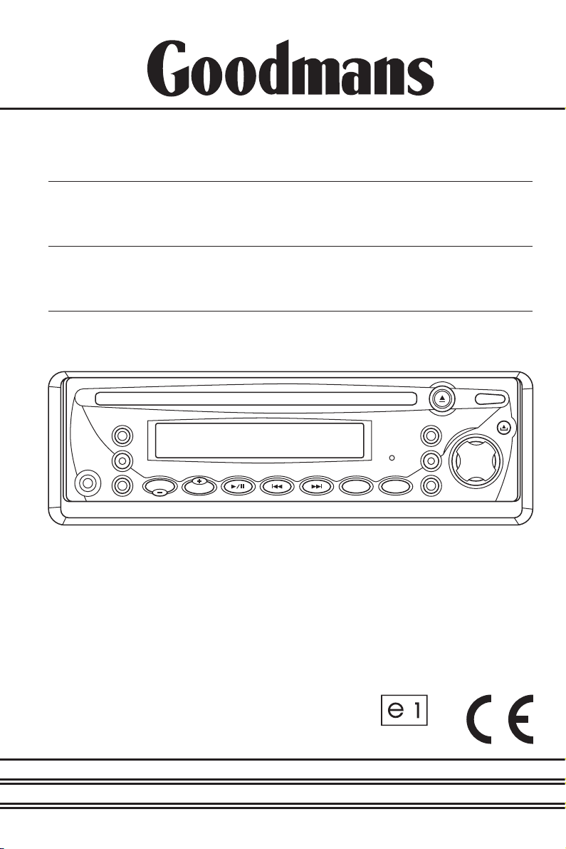
INSTRUCTION
MANUAL
Model GCE 7301 CD
In Car Radio
Compact Disc Player
022479
Page 2

CONTENTS
Accessories...................................................................................................Page 3
Important Notes ............................................................................................Page 4
Precautions and Maintenance ......................................................................Page 5
Installation/Precautions.................................................................................Page 6
Removing and Attaching the Trim Ring ........................................................Page 7
Using the Detachable Front Panel ................................................................Pages 8 - 9
Wiring Identification ......................................................................................Page 10
ISO Plug Connections...................................................................................Pages 11 - 12
Identification of Controls and Functions.......................................................Pages 13 - 15
Aerials and Aerial Fitting ...............................................................................Page 16
Radio Reception ...........................................................................................Page 16
Radio Interference.........................................................................................Page 17
Trouble Checks and Trouble Shooting..........................................................Pages 18 - 19
Specifications................................................................................................Page 20
CONTENTS
Please note: An integrally mounted screen aerial may give rise to increase multipath
MULTIPATH DISTORTION / MUTING
distortion or spurious muting of the audio output. This is normal and to be expected.
The use of an externally mounted rod aerial may reduce or possibly eliminate such
problems.
Most screen aerials require a 12 volt supply to operate correctly. Please check that this
has been connected the +12 volt antenna wire of your radio. If you are in any doubt of
this connection please consult your vehicle dealer or the Goodmans installation helpline.
IMPORTANT: Do not forget to remove the transit screws on top of the unit.
Before removing the fixing cage and installing the unit.
Failure to do so will result in the CD not playing.
2
P. 2
Goodmans Product Information Helpline (0870) 873 0080
Page 3
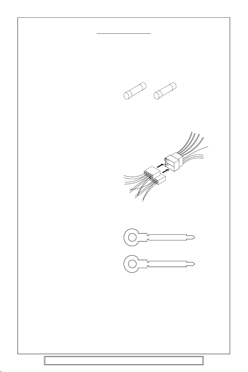
ACCESSORIES
Please retain the carton and packing materials, as this is the best protection for the unit
should it be necessary to return it for servicing.
(1) 1 x 0.5 Amp fuse (spare fuse for + 12 volt supply wire of the unit).
1 x 5 Amp fuse (spare for memory wire).
5A Fuse 0.5A Fuse
(2) 2 x ISO Plug Connector
For use when ISO plugs are not
already used on your vehicle
Main Unit
ISO Socket
(3) 2 x Release key
P. 3
Goodmans Product Information Helpline (0870) 873 0080
Page 4
PLEASE READ THIS BEFORE CONNECTING THE
PLAYER TO THE VEHICLE
IMPORTANT NOTES
Prior to final installation carry out a sound check. If high distortion or intermittent sound
is experienced it is possible that the wiring to the car’s electric is poor, or that the battery
needs recharging.
If the battery and its charging circuit are OK, then rewire the red fused wire of the player
directly to the positive terminal (+) of the car battery. Car accessory shops stock the
connector blocks and the 5 Amp cable which may be necessary for extending the fuse
wire connection.
EARTHING: Make sure that the black wire on the wiring harness is connected to a good
earthing point on the car. If the chassis of the car is used as an earthing point, make sure
that the paint is scraped clean from the metal work before attaching the wire to it. It is
preferable to connect the black earthing wire directly to the negative terminal (–) of the
car battery.
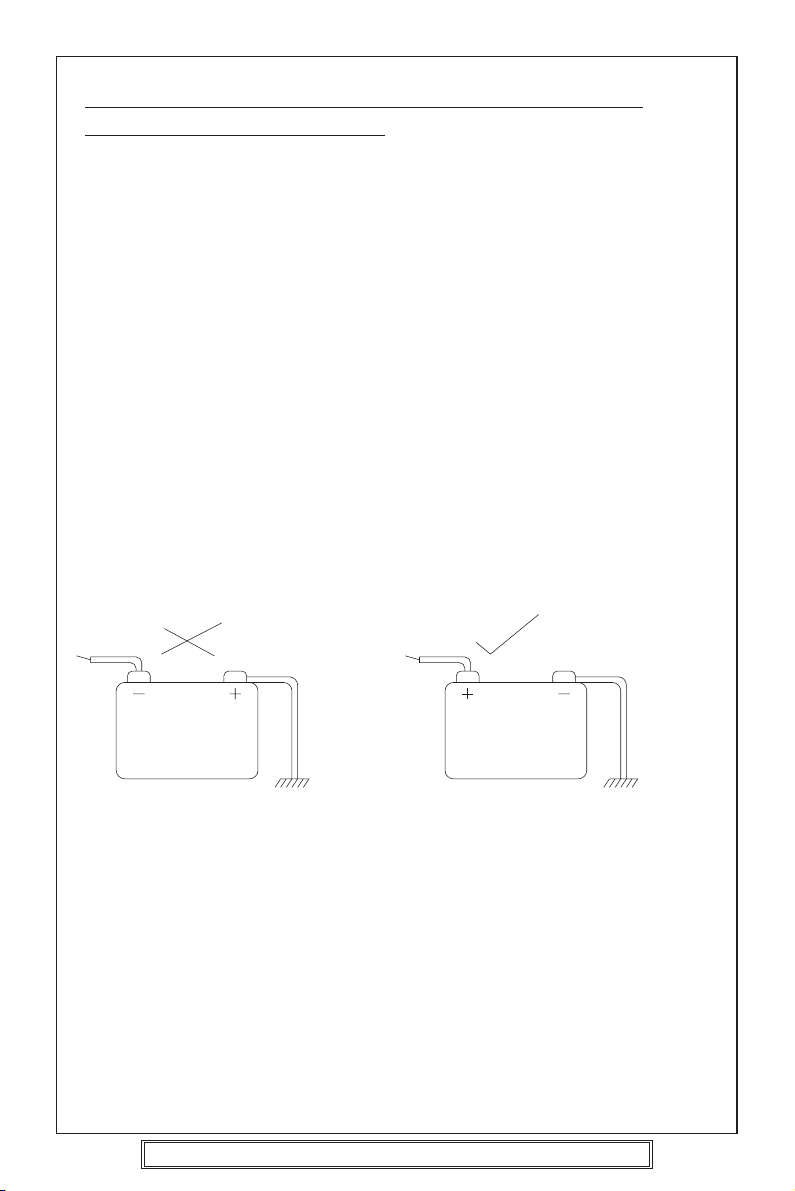
WARNING: POLARITY.....
This model is only suitable for use in vehicles which have a negative earth system.
e.g.: The negative terminal of the car battery is connected to the chassis.
12V
BATTERY
POSITIVE
CHASSIS
12V
BATTERY
NEGATIVE
CHASSIS
Connecting The Speakers And Power Cables
Before you wire your system, disconnect your vehicle battery’s positive (+) cable.
This helps prevent damage in case of a short. When you complete the wiring, reconnect
the battery cable and test your car stereo.
Note: Check with your vehicles handbook or dealer before disconnecting the vehicle
battery in case the alarm or other electronics in your vehicle requires special attention.
When connecting your car stereo’s black ground wire, be sure to connect the wire to a
metal part of your vehicle or preferably to the negative (–) terminal of the car battery.
P. 4
Goodmans Product Information Helpline (0870) 873 0080
Page 5

PRECAUTIONS AND MAINTENANCE
• This unit is designed for negative ground 12V DC operation only. The equipment can
be used safely, if the negative terminal of the battery is connected to the vehicle metal
work.
• Do not use speakers of impedance less than 4 ohms; and do not allow the speaker
wires to be sorted together when the unit is switched on.
Otherwise it may overload or burn out the power amplifier stage.
• If the car interior is extremely hot, as after being parked in the sun, do not use the
player until the car has been driven for a while to cool off the interior.
Caution Vauxhall owners:
Vauxhall do not follow normal ISO wiring convention which will cause Goodmans radios’
to lose the radio preset memories each time the ignition switch is turned off. To prevent
such occurrences swap over the Red ignition and Orange Memory wires in the bullet
connectors attached to the wiring harness of the car radio.
P. 5
Goodmans Product Information Helpline (0870) 873 0080
Page 6
INSTALLATION/PRECAUTIONS
• Choose the mounting location carefully so that the unit will not interfere with the normal
driving functions of the vehicle.
• Avoid installing the unit where it would be subject to high temperatures, such as from
direct sunlight or hot air from the heater, or where it would be subject to dust, dirt or
excessive vibration.
• Use only the supplied mounting hardware for a safe and secure installation.
• Be sure to remove the front panel before installing the unit.
Mounting angle adjustment
Adjust the mounting angle to less than 20°.
MOUNTING EXAMPLE
Installation in the dashboard
* Remove trim ring
* Insert release keys
12
* Pull unit away from cage
Fix cage to car
slot
3
Ta b
Bend these claws, if necessary
Insert radio into car slot
Insert cage into car slot
182m
Attach the: ISO connecting cables
4
To the sockets location
ISO
connecting
plugs
CD changer cable
Car aerial
Car aerial
53m
5
Note:
Keep the release keys in a safe place as you may need them in future to remove the unit
from the car.
P. 6
Goodmans Product Information Helpline (0870) 873 0080
Page 7

REMOVING AND ATTACHING THE TRIM RING
This model can be fitted to DIN E or ISO style dashboard slots. The clip on
trim ring is prefitted to the front of the unit for this purpose.
• It will be necessary to remove the trim ring:
a. To allow the radio to be fitted to an ISO style dashboard slot.
b. To gain access to the keyhole slots for removal of the unit from the car
slot/fixing cage.
• To remove the trim ring first remove the front panel from the radio (press the
open button and remove the front panel).
• Using your fingers lift the trim ring at its top centre and pull the ring towards
you/away from the main unit.
• The trim ring can only be fitted to the main unit one way only. A removable
label with TOP printed on it is placed on the top of the ring to indicate the
correct placement of the ring. Simply position the trim ring over the front
of the main unit and push fit the trim ring on to the unit.
Lift up and then pull
away from unit.
TOP
Trim Ring
REMOVING THE PLAYER FROM THE DASHBOARD/FIXING BRACKET
• Remove the front panel from the main unit.
• Lift off the trim ring and remove from the main unit.
• Insert the supplied release keys into the key slots located on the left and
right sides of the unit. Ensure that the keys are fully pressed into the slots.
• Pull on both of the release keys to remove the unit from the fixing bracket/car
slot.
Insert keys into key holes
and pull to remove unit.
P. 7
Goodmans Product Information Helpline (0870) 873 0080
Page 8

THE DETACHABLE FRONT PANEL
To Detach the Front Panel
1. Press the release button (REL), then the right-hand side of the panel will be ejected.
Release Button
2. Remove the front panel by pulling its right-hand side outward.
Front Panel
3. For safekeeping, store the front panel in the supplied protective case immediately
after being removed.
Protective Case
Front Panel
P. 8
Goodmans Product Information Helpline (0870) 873 0080
Page 9

To Reinstall the Front Panel
1. Push the front panel into the main body. A ‘click’ sound should be heard.
2. Note that if the front panel fails to lock in position properly, the control buttons on the
front panel may not function correctly and LCD display may be missing some
segments. Press the release button and then reinstall the front panel again.
Precautions when Handling
1. Do not drop the front panel.
2. Do not put pressure on the display or control buttons when detaching or reinstalling
the front panel.
3. Do not touch the contacts on the front panel or on the main unit body. It may result
in poor electrical contact.
4. If any dirt or foreign substances is stuck on the contacts, remove with a clean and
dry cloth.
5. Do not expose the front panel to high temperatures or direct sunlight.
6. Keep away any volatile agents (e.g. benzene, thinner, or insecticides) from touching
the surface of the front panel.
7. Do not attempt to disassemble the front panel.
P. 9
Goodmans Product Information Helpline (0870) 873 0080
Page 10

WIRING IDENTIFICATION
UNIT
1
2
3
4
6
7
REAR VIEW OF PLAYER
1) AERIAL INPUT SOCKET 8) FRONT RIGHT POSITIVE: WHITE
2) BATTERY: RED +12 VOLT IGNITION 9) FRONT RIGHT NEGATIVE: WHITE
3) GROUND: BLACK – WITH BLACK STRIPE
4) MEMORY: ORANGE 10) REAR LEFT POSITIVE: BROWN
PERMANENT +12 VOLT 11) REAR LEFT NEGATIVE: BROWN
5) AUTO AERIAL: ORANGE/WHITE WITH BLACK STRIPE
6) FRONT LEFT POSITIVE: GREY 12) REAR RIGHT POSITIVE: YELLOW
7) FRONT LEFT NEGATIVE: GREY 13) REAR RIGHT NEGATIVE: YELLOW
WITH BLACK STRIPE WITH BLACK STRIPE
RECOMMENDED MINIMUM LOUDSPEAKER POWER RATINGS
Front loudspeakers power ratings 2 x 10 Watts RMS (2 x 15 Watts Music)
Rear loudspeakers power ratings 2 x 10 Watts RMS (2 x 15 Watts Music)
TWO SPEAKER WIRING
If only two speakers are going to be used with this radio select either front or rear wiring
INSTALLATION NOTES
(APPLICABLE TO BOTH 2 AND 4 SPEAKER CONNECTION)
This radio contains two separate power amplifiers, to prevent possible damage to these
amplifiers please ensure:
1) The vehicle chassis is not used as a loudspeaker earth (–ve return).
2) Front and Rear loudspeaker connecting wires are not joined together.
3) Any wires not used when completing a two speaker installation are fully insulated.
4) The memory wire (Orange) is connected to a permanent +12V supply.
5) The power wire (Red) is connected via the ignition switch of the vehicle.
5
8
9
1210
1311
Note: Before turning the unit ON for the first time after installation please ensure the
RESET button is pressed to reset the microprocessor.
IMPORTANT NOTE
If after directly connecting the unit via the vehicles ISO connector plugs it does not appear
to work (fails) to power up disconnect the orange lead bullet connector and reconnect to
the twin bullet connector socket on the red wire. Try the unit again it should power up and
can be used normally. Note this phenomenon is most frequent in Volkswagen/Audi vehicles.
P. 10
Goodmans Product Information Helpline (0870) 873 0080
Page 11

ISO PLUG CONNECTIONS
ISO - Plug
1357
B
2468
ISO - PLUG
1357
A
2468
CARRADIO
Filter
Box
AERIAL SOCKET
A8
A4
A7
A5
B1
B2
B3
B4
B5
B6
B7
B8
Block A: This plug is used for power supply connections only.
Block B: This plug is used for connecting the loudspeakers.
• If your vehicle is not fitted with an ISO connector but just bare wire, then
simply connect the supplied ISO plug to bare wire connector A and B to the
radio’s ISO socket and connect the bare wire ends to the vehicles loudspeakers
according to the wiring codes as shown below. Make sure all connections
and any unused wires are insulated to prevent shorting.
• ISO Connector pin A6 (Car Light Illumination) is not used on this player.
ISO-PLUG A
ISO Function Colour
A4
A5
A7
A8
A6
+12 Volt memory
+ 12 Volt Auto. Antenna
+12 Volt Power
Earth (Ground)
Car light (Illumination)
Orange
Orange/White
Red
Black
---
ISO-PLUG B
ISO Function Colour
B1 Speaker right rear +
B2 Speaker right rear –
Yellow with black stripe
B3 Speaker right front +
B4 Speaker right front –
White with black stripe
B5 Speaker left front +
B6 Speaker left front –
Grey with black stripe
B7 Speaker left rear +
B8 Speaker left rear –
P. 11
Goodmans Product Information Helpline (0870) 873 0080
Brown with black stripe
Yellow
White
Grey
Brown
Page 12

Recommended Minimum Loudspeaker Power Ratings
Front and Rear Loudspeakers power ratings 4 x 10 Watts RMS.
Two Speaker Wiring
If only two speakers are going to be used with this radio select either front or rear wiring
in accordance with the power handling of the speakers fitted to you vehicle, when
installing connect as per the instructions given on page 10 - 11.
Installation Notes
(Applicable to both 2 and 4 speaker connection)
This radio contains two separate power amplifiers, to prevent possible damage to these
amplifiers please ensure:
i) The vehicle chassis is not used as a loudspeaker earth (-ve) return.
ii) Front and Rear loudspeaker connection wires are not joined together.
iii) Any wires not used when completing a two speaker installation are fully insulated.
iv) The memory wire (orange) is connected to a permanent +12V supply.
v) The power wire (Red) is connected via the ignition switch of the vehicle.
If bare wires are to be used, insert the 2 x supplied ISO plugs into the ISO socket of the
car radio.
The plugs are handed and will only fit one way. Connect the bare wires ends in
accordance with the instructions given on page 10.
P. 12
Goodmans Product Information Helpline (0870) 873 0080
Page 13

IDENTIFICATION OF CONTROLS AND FUNCTIONS
10
21
12 13
43 976
18
85
19 20 211716151411
22
FUNCTION KEYS
1. Mode Button 12. Volume - Button
2. Mute Button 13. Volume + Button
3. Disc Slot 14. Disc PLAY/PAUSE Button
4. Liquid Crystal Display 15. Button
5. Reset Button 16. Button
6. RND/LOU Button 17. Display Button
7. Eject Button 18. Band Button
8. Power Button 19. REP/LOC Button
9. Release Button 20. INT/MON Button
10. Auxiliary Input Socket 21. Tuning Knob
11. Select Button 22. Flashing LED
P. 13
Goodmans Product Information Helpline (0870) 873 0080
Page 14

GENERAL OPERATION
• ON/OFF
Press the PWR button (8) to turn on. Press PWR again to turn off.
• MUTE
Press the MUT button (2) to mute the sound. Press it again to return volume to
previous level.
• FACEPLATE RELEASE
Press button (9) to release the removable faceplate.
• LOUDNESS
Press RND/LOU button (6) briefly to enhance bass output.
• SET THE CLOCK
Press DSP button (17) to change the display to clock display. Press it again to return
to previous display. In clock display, press and hold the DSP button (17) for several
seconds until the clock display flashes. Press VOL – button (12) to change minutes
or VOL + button (13) to change hours.
• SELECT AUDIO MODE
Press SEL button (11) to change audio mode through volume, bass, treble, balance
and fader modes.
Use VOL + (13) and VOL – (12) buttons to adjust the selected mode.
When mode has not been adjusted for several seconds, display returns to normal
radio or CD display.
Volume
Adjust volume level by using VOL + (13) and VOL – (12) buttons.
Notes: The unit is initially set to volume mode.
Bass
Press SEL button (11) once.
Adjust bass level by using VOL + (13) and VOL – (12) buttons.
Treble
Press SEL button (11) twice.
Adjust treble level by using VOL + (13) and VOL – (12) buttons.
Balance
Press SEL button (11) three times.
Adjust the balance between left and right speakers by using VOL + (13) and VOL –
(12) buttons.
Fader
Press SEL button (11) four times.
Adjust the balance between front and rear speakers by using VOL + (13) and VOL –
(12) buttons.
• SELECT MODE
Press MOD button (1) to choose radio or CD mode.
• LIQUID CRYSTAL DISPLAY
The LCD (4) displays the current information for the radio or CD.
• FLASHING LED
If the front panel is detached from the main unit, the LED (22) will flash.
• AUXILIARY INPUT
The unit can be connected to a portable audio player through the AUX IN socket (10).
• RESET BUTTON FUNCTION
RESET button (5) is located on the front panel and must be pressed with either a ball
point pen or thin metal object. The RESET button (5) should be used for the following
Volume Bass Treble Balance Fader
P. 14
Goodmans Product Information Helpline (0870) 873 0080
Page 15

reasons:
- Initial installation of the unit after all wiring is completed.
-
All the function buttons do not operate.
- Error symbol on the display.
Note: In the unlikely event of the unit still malfunctioning after pressing the reset
button, call the Goodmans product information helpline on 0870 873 0080.
RADIO OPERATION
• SELECT BAND
Press Press BAND button (18) to change bands as below:
FM MW LW
• TUNING TO STATIONS
Rotate TUNING knob (21) clockwise or anti-clockwise to adjust the frequency until the
desired station is found.
• LOCAL/DISTANCE
Press the REP/LOC button (19) to select between local setting for reception of strong
station and distant setting for reception of weak stations when tuning.
• MONO/STEREO
If there is noise on the station being listened to in FM STEREO, press the INT/MON
button (20) and the noise may be reduced. To return to receiving station in stereo,
press this button again.
CD OPERATION
• DISC PLAY
Gently insert a compact disc with the label side facing up into the disc slot (3). The
disc is then automatically loaded into the unit and starts playback with the first track
of the disc.
The display will indicate the track number and the elapsed time of the track.
• EJECT
Press EJECT button (7) to stop CD playback and eject CD from slot.
Receiver switches to radio operation.
• PAUSE CD
During CD playing, press
playback.
• SKIP TRACKS
Press (16) or button (15) to skip to the following track or the previous track.
The track numbers will be shown on display.
• FAST FORWARD AND FAST REVERSE
Press and hold button (16) or button (15) for several seconds to search
forward or reverse at high speed. Release the button to resume normal playback.
• REPEAT
During CD playback, press REP/LOC button (19) to repeat the current track. Press the
button again to resume normal playback.
• INTRO: PREVIEW ALL TRACKS
During CD playback, press INT/MON button (20) to play first few seconds of each
track. Press it again to cancel intro mode and listen to track.
• RANDOM: PLAY ALL TRACKS IN THE RANDOM ORDER
During CD playback, press and hold RND/LOU button (6) for several seconds to play
all tracks in random order. Press and hold again to cancel the function and resume
normal playback
button (14) to pause playback. Press it again to resume
P. 15
Goodmans Product Information Helpline (0870) 873 0080
Page 16

AERIALS AND AERIAL FITTING
The normal standard telescopic aerial is designed to be used fully extended. If any
segments are damaged or missing this will result in a deterioration of the radio reception.
If is important to keep the aerial clean which will prevent corrosion and subsequent high
resistance occurring within the segments which will lead to noisy or poor reception.
NOTE: Special aerial cleaning fluid is available from most garages and car radio
specialists.
The ISO connector is supplied with a wire for use with an electrically powered aerial.
Each time the radio cassette player is turned on +12 Volts appears on this wire. This wire
must only be connected to the +12 Volt input terminal of the relay supplied with an electric
aerial (refer to the instructions supplied with the aerial). When the aerial has been fitted
correctly it will automatically extend when the power control of the radio cassette player
is turned on, and will retract when turned off. This type of aerial is excellent against
vandalism if you are prone to forgetting to retract your manual type aerial.
When fitting an aerial always try to sight the aerial as far away from the engine electric
as possible, this will ensure that any ignition interference is kept to a minimum. Always
make sure that the aerial is secured to a paint/underseal/rust free surface.
RADIO RECEPTION
FM BAND: FM (Frequency Modulated) transmissions are far superior in sound quality
than AM transmissions (MW, LW).
The signal can be affected by many factors such as car ignition, tall buildings, metal
objects such as cranes or gasometers, hills, trees, wet weather, hot weather etc. In
general, an increasing amount of noise and interference will be picked up by the radio
the further away it is from the transmitter. When driving through built up areas or along
a motorway, the FM reception may be patchy, this is due to the signal being momentarily
blocked or reduced by an object and then reappearing when the object has been passed,
this is heard as a shushing noise and is unfortunately unavoidable.
AM BAND: AM (amplitude modulated) in addition to the FM band, the receiver is capable
of receiving Medium Wave (MW) and Long Wave (LW) bands. These signals may be
received over very long distances because the transmitting signal will bend around the
curvature of the earth. These transmissions are affected by similar factors to the FM band,
but in addition to this the reception will alter as night falls. The ionised layer in the upper
atmosphere changes at night and allows more distant signals to be reflected back down
to the earth. Subsequently more stations will appear on the waveband and this may cause
tuning difficulties or co-channel interference (where 2 or more stations occupy the same
frequency on the waveband). If the interference is severe, retuning to an alternate frequency
(BBC often use more than 1 frequency) or selecting and tuning into a different waveband
may be necessary.
P. 16
Goodmans Product Information Helpline (0870) 873 0080
Page 17

RADIO INTERFERENCE
In the event that your player suffers from interference from your vehicles ignition or
charging system, please read carefully the guidance given below. It should be noted that
in the majority of cases, interference is mostly caused by a missing or defective device
or the ignition HT leads are worn or are of poor quality.
SUPPRESSING THE IGNITION COIL
TO CONTACT BREAKER CB–
COIL
The ignition circuit consists of the coil, distributor, spark plug leads, and spark plugs, all
of these components pass very high voltage and unless they are screened or suppressed
will cause electrical interference to the radio. This can occur in any of the following ways:
a. Travel along the +12 Volt supply cable to the radio or
b. As a radio frequency which is received by the car aerial and processed as a signal or
c. By both points a and b shown above.
Before replacing or adding any suppression devices or filters, check carefully that the car
aerial and screened lead are not damaged and that the radio cassette player is properly
earthed and tuned to the correct frequency. As radio interference can be caused by many
factors, locating the exact cause of the problem can often be very difficult, and trouble
shooting is usually best left to a professional car radio installer, or to the main agent of
your vehicle.
If you decide to try and cure the problem yourself, the large array of suppression kits/devices
currently available from high street motor factors or your vehicles main agent may be
confusing you. Each type of device is designed to filter out electrical interference at
specific frequencies it is unfortunately trial and error, if one device works and another
does not, therefore you may have to try several different types of filters before you have
any success. Instructions on fitting the filters etc. are usually supplied with the kits.
TO IGNITION SWITCH +12 VOLT
1 MFD CAPACITOR
Another source of interference is the alternator or dynamo, this can cause a whining noise
relative to the engine speed. The alternator/dynamo should be fitted with a 2.2 MFD
capacitor which should be connected between the +B lead (usually the thickest lead) and
the car chassis or body of the alternator.
P. 17
Goodmans Product Information Helpline (0870) 873 0080
Page 18

TROUBLE SHOOTING
The following indicator is shown on the display.
E1, E2, E3 Press the RESET button.
If this indicator still appears after pressing the RESET button, call
the Goodmans Product Information helpline on 0870 873 0080.
BEFORE SET REMOVAL
1 Take out the disc. If a disc remains in the CD player,
2 Turn off the power switch.
CAUTION:
Metal parts of this unit (especially on the back) become quite hot during operation,
be careful to avoid touching parts immediately after removing the unit.
the disc or set may be seriously
damaged in transportation.
TROUBLE SHOOTING
The following checks will assist in the correction of most problems which you may
encounter with your unit. Should any problem persist after you have made these
checks, call the Goodmans Product Information helpline on 0870 873 0080.
Before going through the check list first refer back to the connection and operating
procedures.
Symptom Cause Solution
No power. The car’s ignition switch is not If the power supply is connected to
on. the car’s accessory circuits, switch
the ignition key to “ACC”.
The fuse is blown. Replace the fuse with another 5A or
Disc will You are trying to put in the Insert the compact disc with the label
not play. compact disc up-side down. side facing up.
The compact disc is extremely Clean the compact disc, try to play
dirty or defective disc. a new one.
The temperature in the car is Cool off the inside of the car, then try
too high. again.
Condensation. Leave the disc player off for an hour
Goodmans Product Information Helpline (0870) 873 0080
0.5A fuse.
or so, then try again.
P. 18
Page 19

Symptom Cause Solution
No sound. Adjust the volume control. Adjust the sound to the level you
want.
Unit is not connected properly. Double check the connections.
The connection cords are not Check the speaker cords and the
connected properly. other connection cords.
The The built-in microcomputer is Remove the compact disc, then
operation operating incorrectly. insert it again.
keys do not Press the reset button.
work.
Sound The installation angle is greater Adjust the angle to less than 30°.
skips. than 30°.
The disc player is not correctly Fasten the disc player securely.
secured.
Sound The compact disc is extremely Clean the compact disc, try to play a
skips. dirty or defective disc. different disc.
Condensation. Leave the disc player off for an hour
or so, then try again.
The sound The compact disc is defective. Try another disc.
quality is If that disc plays properly, the first
poor. disc is defective.
The compact disc is dirty. Clean the disc.
The radio The aerial cable is not Insert the aerial cable solidly.
does not connected.
work.
P. 19
Goodmans Product Information Helpline (0870) 873 0080
Page 20

SPECIFICATIONS
GENERAL
Power Supply Requirements : DC 12 Volts, Negative Ground
Chassis Dimensions : 178 (W) x 163 (D) x 50 (H)
Tone Controls
- Bass (at 100 Hz) : ± 7 dB
- Treble (at 10 KHz) : ± 7 dB
Maximum Output Power : 4 x 10W RMS
Current Drain : 3 Ampere (max.)
CD PLAYER
Signal to Noise Ratio : More than 55 dB
Channel Separation : More than 40 dB
Frequency Response : 50 Hz - 15 KHz
RADIO
Frequency Coverage : 87.5 to 108 MHz
FM
IF : 10.7 MHz
Sensitivity (S/N = 30 dB) : 15 µV
Stereo Separation : > 25 dB
MW
Frequency Coverage : 522 to 1620 KHz
IF : 450 KHz
Sensitivity (S/N = 20 dB) : 36 dBu
LW
Frequency Coverage : 144 to 288 KHz
IF : 450 KHz
Sensitivity (S/N = 20 dB) : 45 dBu
P. 20
Goodmans Product Information Helpline (0870) 873 0080
88-C1294-08
 Loading...