

Page 1
INSTRUCTION
MANUAL
Model GCE 7007DAB
In Car DAB/RDS Radio
Compact Disc Player
Page 2

CONTENTS
Accessories...................................................................................................Page 3
Important Notes ............................................................................................Page 4
Precautions and Maintenance ......................................................................Page 5
Installation/Precautions.................................................................................Page 6
Removing and Attaching the Trim Ring ........................................................Page 7
Using the Detachable Front Panel ................................................................Pages 8 - 9
Wiring Identification ......................................................................................Page 10
ISO Plug Connections...................................................................................Pages 11 - 12
Identification of Controls and Functions.......................................................Pages 13 - 29
Aerials and Aerial Fitting ...............................................................................Page 30
Radio Reception ...........................................................................................Page 30
Radio Interference.........................................................................................Page 31
Trouble Checks and Trouble Shooting..........................................................Pages 32 - 33
Specifications................................................................................................Page 34
MULTIPATH DISTORTION / MUTING (FM RDS)
Please note: An integrally mounted screen aerial may give rise to increase multipath
distortion or spurious muting of the audio output. This is normal and to be expected.
The use of an externally mounted rod aerial may reduce or possibly eliminate such
problems.
Most screen aerials require a 12 volt supply to operate correctly. Please check that this
has been connected to the +12 volt antenna wire of your radio. If you are in any doubt
of this connection please contact the vehicle dealer or Goodmans installation helpline.
IMPORTANT: Do not forget to remove the transit screws on top of the unit,
before removing the fixing cage and installing the unit.
Failure to do so will result in the CD not playing.
P. 2
Goodmans Product Information Helpline (02392) 391100
Installation Helpline (01132) 868613
Page 3
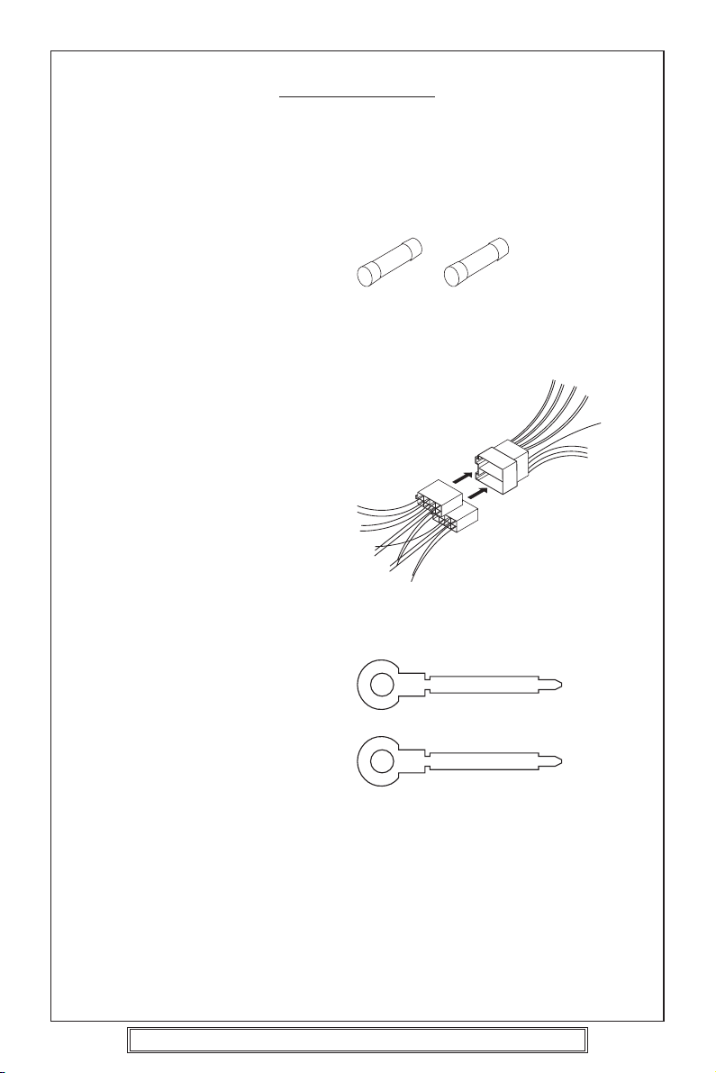
ACCESSORIES
Please retain the carton and packing materials, as this is the best protection for the unit
should it be necessary to return it for servicing.
(1) 1 x 15 Amp fuse (spare fuse for + 12 volt supply wire of the unit).
1 x 0.5 Amp fuse (spare for memory).
15A Fuse 0.5A Fuse
(2) 2 x ISO Plug Connector
For use when ISO plugs are not
used on your vehicle
Main Unit
ISO Socket
(3) 2 x Release key
P. 3
Goodmans Product Information Helpline (02392) 391100
Installation Helpline (01132) 868613
Page 4
PLEASE READ THIS BEFORE CONNECTING THE
PLAYER TO THE VEHICLE
IMPORTANT NOTES
Prior to final installation carry out a sound check. If high distortion or intermittent sound
is experienced it is possible that the wiring to the car’s electric is poor, or that the battery
needs recharging.
If the battery and its charging circuit are OK, then rewire the red fused wire of the player
directly to the positive terminal (+) of the car battery. Car accessory shops stock the
connector blocks and the 15 Amp cable which may be necessary for extending the fuse
wire connection.
EARTHING: Make sure that the black wire on the wiring harness is connected to a good
earthing point on the car. If the chassis of the car is used as an earthing point, make sure
that the paint is scraped clean from the metal work before attaching the wire to it. It is
preferable to connect the black earthing wire directly to the negative terminal (–) of the
car battery.
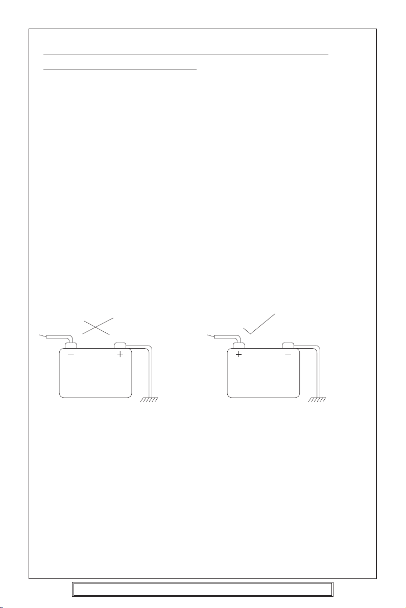
WARNING: POLARITY.....
This model is only suitable for use in vehicles which have a negative earth system.
e.g.: The negative terminal of the car battery is connected to the chassis.
12V
BATTERY
POSITIVE
CHASSIS
12V
BATTERY
NEGATIVE
CHASSIS
Connecting The Speakers And Power Cables
Before you wire your system, disconnect your vehicle battery’s positive (+) cable.
This helps prevent damage in case of a short. When you complete the wiring, reconnect
the battery cable and test your car stereo.
Note: Check with your vehicles handbook or dealer before disconnecting the vehicle
battery in case the alarm or other electronics in your vehicle requires special attention.
When connecting your car stereo’s black ground wire, be sure to connect the wire to a
metal part of your vehicle or preferably to the negative (–) terminal of the car battery.
P. 4
Goodmans Product Information Helpline (02392) 391100
Installation Helpline (01132) 868613
Page 5
PRECAUTIONS AND MAINTENANCE
• This unit is designed for negative ground 12V DC operation only. The equipment can
be used safely, if the negative terminal of the battery is connected to the vehicle metal
work.
• Do not use speakers of impedance less than 4 ohms; and do not allow the speaker
wires to be shorted together when the unit is switched on.
Otherwise it may overload or burn out the power amplifier stage.
• If the car interior is extremely hot, as after being parked in the sun, do not use the
player until the car has been driven for a while to cool off the interior.
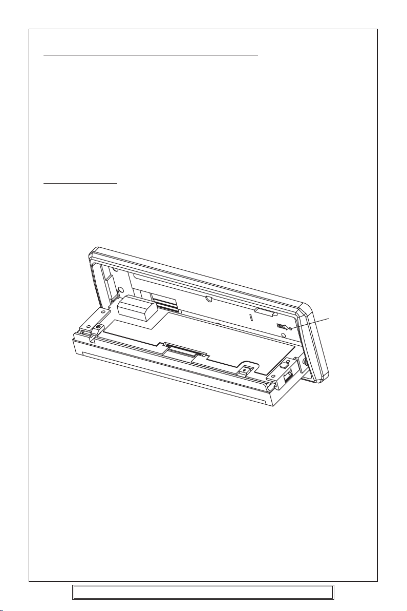
IMPORTANT
After installing the unit, switch on the power to the unit and press this RESET button
using a pen or thin match stick.
RESET
Caution Vauxhall owners:
Vauxhall do not follow normal ISO wiring convention which will cause Goodmans radios’
to lose the radio preset memories each time the ignition switch is turned off. To prevent
such occurrences swap over the Red ignition and Orange Memory wires in the bullet
connectors attached to the wiring harness of the car radio.
P. 5
Goodmans Product Information Helpline (02392) 391100
Installation Helpline (01132) 868613
Page 6
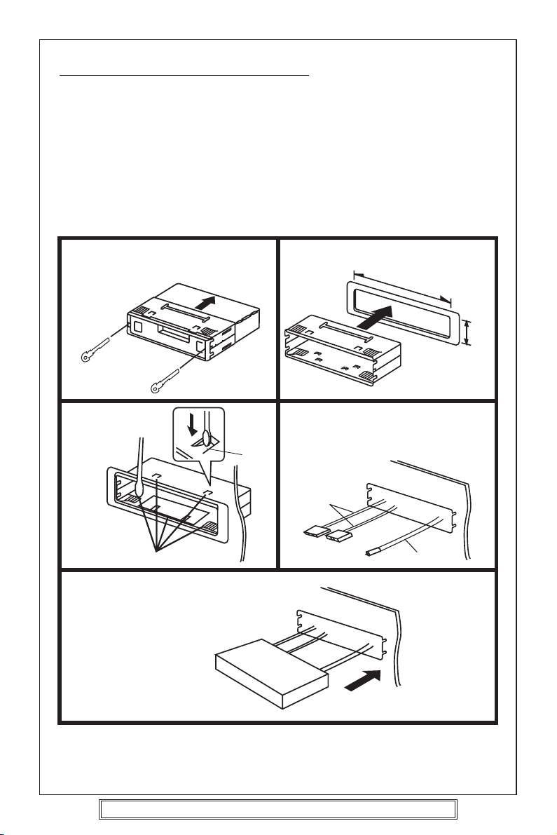
INSTALLATION/PRECAUTIONS
• Choose the mounting location carefully so that the unit will not interfere with the normal
driving functions of the vehicle.
•Avoid installing the unit where it would be subject to high temperatures, such as from
direct sunlight or hot air from the heater, or where it would be subject to dust, dirt or
excessive vibration.
• Use only the supplied mounting hardware for a safe and secure installation.
• Be sure to remove the front panel before installing the unit.
Mounting angle adjustment
Adjust the mounting angle to less than 20°.
MOUNTING EXAMPLE
Installation in the dashboard
* Remove trim ring
* Insert release keys
12
* Pull unit away from cage
Fix cage to car
slot
3
Ta b
Bend these claws, if necessary
Insert radio into car slot
Insert cage into car slot
182m
Attach the: ISO connecting cables
4
To the sockets location
ISO
connecting
plugs
CD changer cable
Car aerial
Car aerial
53m
5
Note:
Keep the release keys in a safe place as you may need them in future to remove the unit
from the car.
P. 6
Goodmans Product Information Helpline (02392) 391100
Installation Helpline (01132) 868613
Page 7
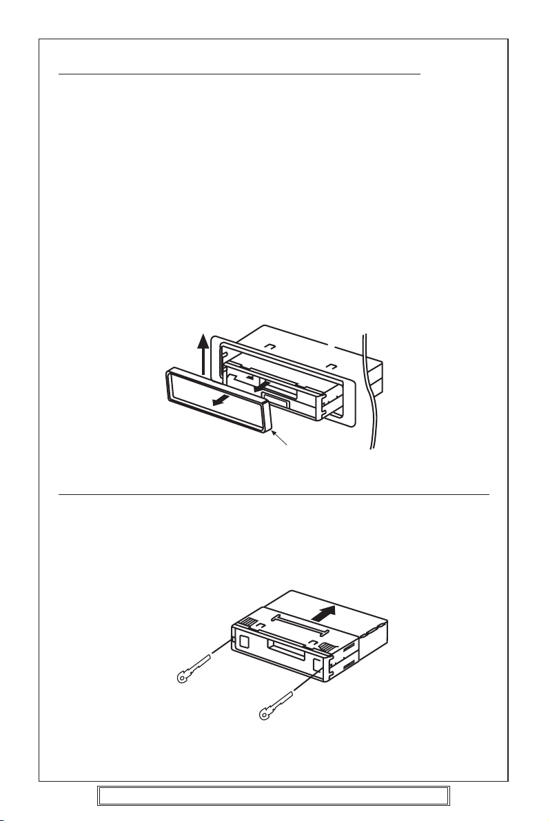
REMOVING AND ATTACHING THE TRIM RING
This model can be fitted to DIN E or ISO style dashboard slots. The clip on
trim ring is prefitted to the front of the unit for this purpose.
• It will be necessary to remove the trim ring:
a. To allow the radio to be fitted to an ISO style dashboard slot.
b. To gain access to the keyhole slots for removal of the unit from the car
slot/fixing cage.
•To remove the trim ring first remove the front panel from the radio (press the
open button and remove the front panel).
• Using your fingers lift the trim ring at its top centre and pull the ring towards
you/away from the main unit.
• The trim ring can only be fitted to the main unit one way only. A removable
label with TOP printed on it is placed on the top of the ring to indicate the
correct placement of the ring. Simply position the trim ring over the front
of the main unit and push fit the trim ring on to the unit.
Lift up and then pull
away from unit.
TOP
Trim Ring
REMOVING THE PLAYER FROM THE DASHBOARD/FIXING BRACKET
• Remove the front panel from the main unit.
• Lift off the trim ring and remove from the main unit.
• Insert the supplied release keys into the key slots located on the left and
right sides of the unit. Ensure that the keys are fully pressed into the slots.
• Pull on both of the release keys to remove the unit from the fixing bracket/car
slot.
Insert keys into key holes
and pull to remove unit.
P. 7
Goodmans Product Information Helpline (02392) 391100
Installation Helpline (01132) 868613
Page 8
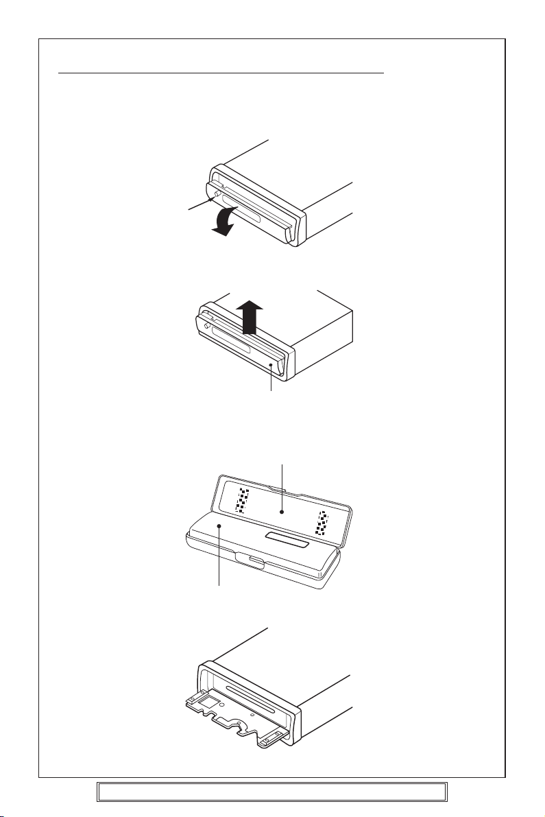
USING THE DETACHABLE FRONT PANEL
To Detach the Front Panel
1. Press the open button (OPEN),then the front panel will be folded down.
Open
2. Remove the front panel by pulling its middle-hand outward.
Front Panel
3. For safekeeping, store the front panel in the supplied protective case immediately
after being removed.
Protective Case
Front Panel
4. Push the front metal plate into the main body. A click sound should be heard.
P. 8
Goodmans Product Information Helpline (02392) 391100
Installation Helpline (01132) 868613
Page 9
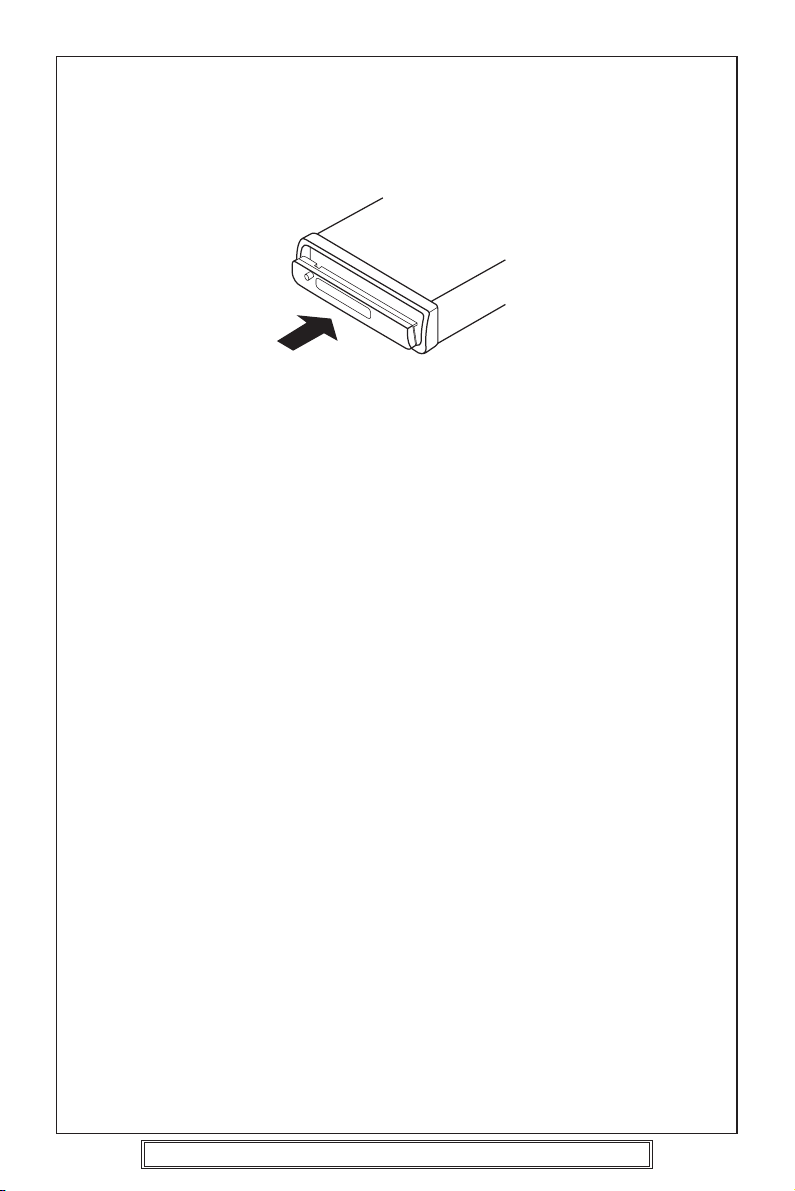
To Reinstall the Front Panel
1. Push the front panel into the main body. A click sound should be heard.
2. Note that if the front panel fails to lock In position properly press control button may
not function and display may be missing some segments. Press the OPEN button
and then reinstall the front panel again.
Precautions when Handing
1. Do not drop the front panel.
2. Do not put pressure on the display or control buttons when detaching or reinstalling
the front panel.
3. Do not touch the contacts on the front panel or on the main unit body. It may result
in poor electrical contact.
4. If any dirt or foreign substances adhered on the contacts, they can be removed with
a clean and dry cloth.
5. Do not expose the front panel to high temperatures or direct sunlight in anywhere.
6. Keep away any volatile agents(e.g. Benzene, thinner. Or insecticides) from touching
the surface of the front panel.
7. Do not attempt to disassemble the front panel.
P. 9
Goodmans Product Information Helpline (02392) 391100
Installation Helpline (01132) 868613
Page 10
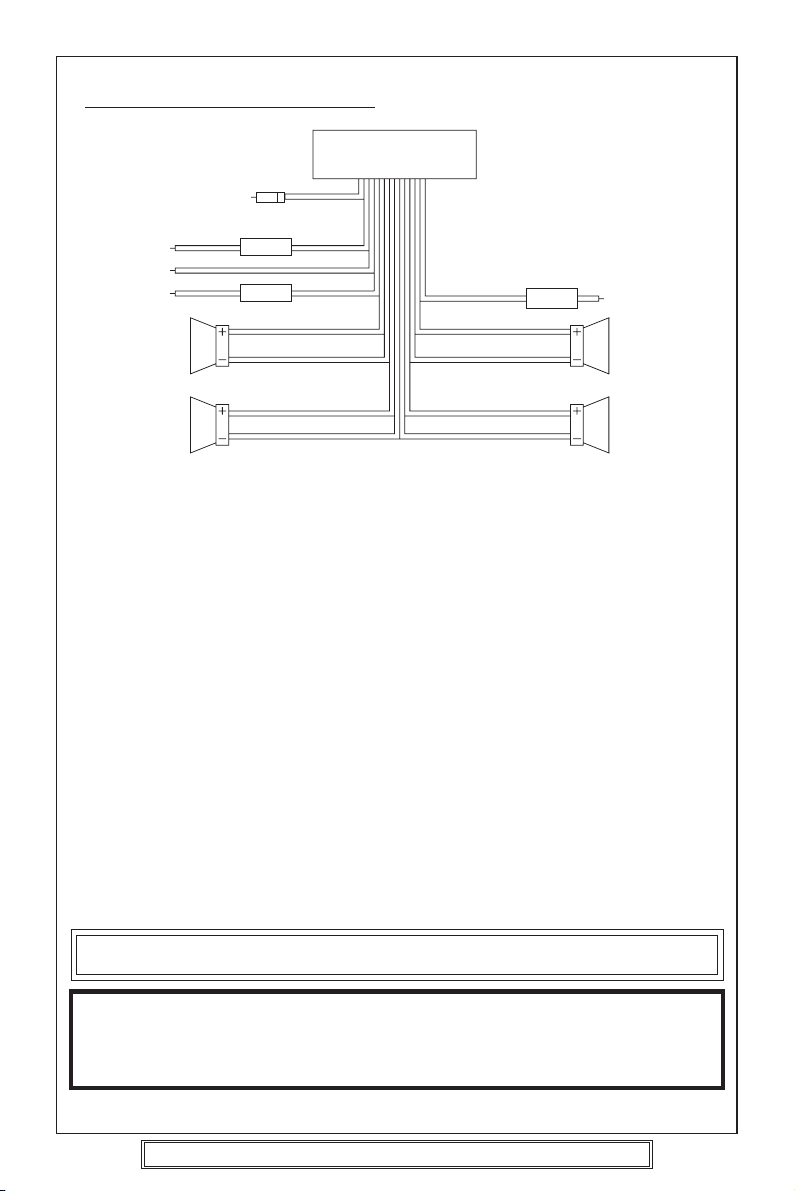
WIRING IDENTIFICATION
UNIT
1
2
3
4
6
7
REAR VIEW OF PLAYER
1) AERIAL INPUT SOCKET 8) FRONT RIGHT POSITIVE: WHITE
2) BATTERY: RED +12 VOLT IGNITION 9) FRONT RIGHT NEGATIVE: WHITE
3) GROUND: BLACK – WITH BLACK STRIPE
4) MEMORY: ORANGE 10) REAR LEFT POSITIVE: BROWN
PERMANENT +12 VOLT 11) REAR LEFT NEGATIVE: BROWN
5) AUTO AERIAL: ORANGE/WHITE WITH BLACK STRIPE
6) FRONT LEFT POSITIVE: GREY 12) REAR RIGHT POSITIVE: YELLOW
7) FRONT LEFT NEGATIVE: GREY 13) REAR RIGHT NEGATIVE: YELLOW
WITH BLACK STRIPE WITH BLACK STRIPE
RECOMMENDED MINIMUM LOUDSPEAKER POWER RATINGS
Front loudspeakers power ratings 2 x 30 Watts RMS (2 x 60 Watts Music)
Rear loudspeakers power ratings 2 x 30 Watts RMS (2 x 60 Watts Music)
TWO SPEAKER WIRING
If you intend to use only two speakers with this radio select either front or rear wiring
INSTALLATION NOTES
(APPLICABLE TO BOTH 2 AND 4 SPEAKER CONNECTION)
This radio contains two separate power amplifiers, to prevent possible damage to these
amplifiers please ensure:
1) The vehicle chassis is not used as a loudspeaker earth (–ve return).
2) Front and Rear loudspeaker connecting wires are not joined together.
3) Any wires not used when completing a two speaker installation are fully insulated.
4) The memory wire (Orange) is connected to a permanent +12V supply.
5) The power wire (Red) is connected via the ignition switch of the vehicle.
5
8
9
1210
1311
Note: Before turning the unit ON for the first time after installation please ensure the
RESET button is pressed to reset the microprocessor. For location see page 13.
IMPORTANT NOTE
If after directly connecting the unit via the vehicles ISO connector plugs it does not appear
to work (fails) to power up disconnect the orange lead bullet connector and reconnect to
the twin bullet connector socket on the red wire. Try the unit again it should power up and
can be used normally. Note this phenomenon is most frequent in Volkswagen/Audi vehicles.
P. 10
Goodmans Product Information Helpline (02392) 391100
Installation Helpline (01132) 868613
Page 11
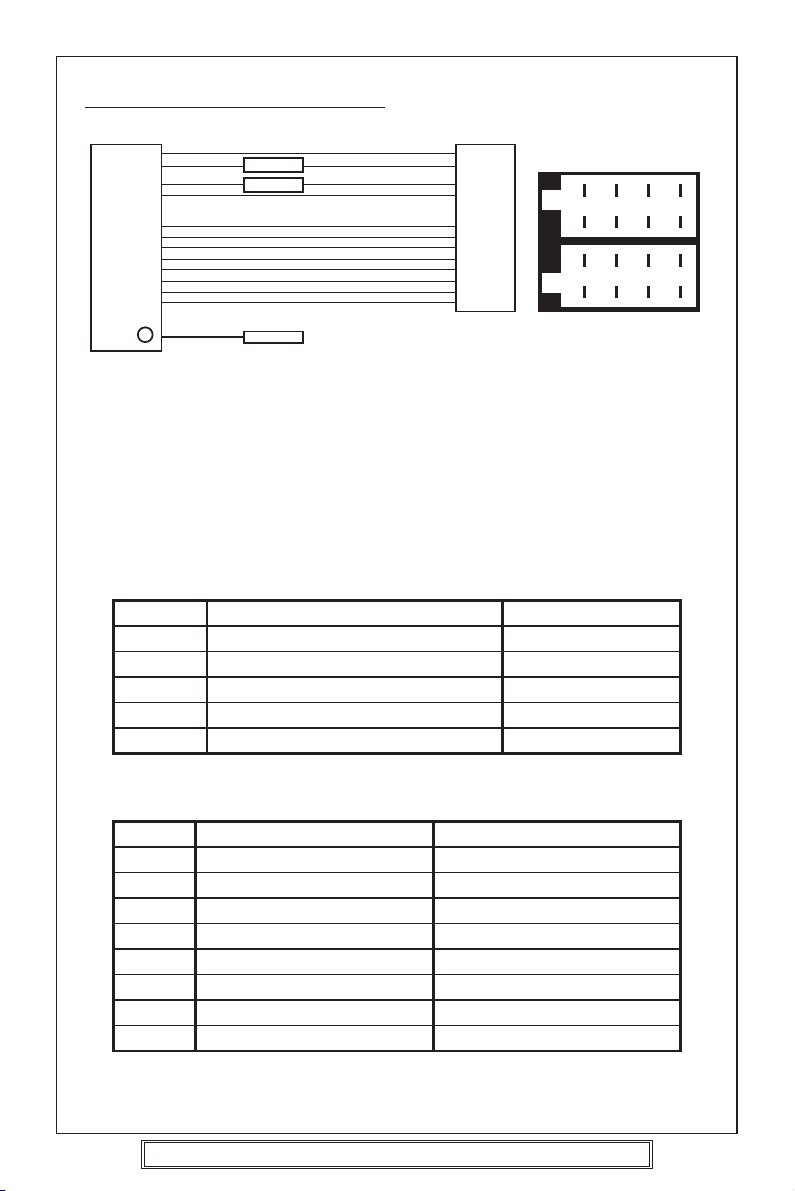
ISO PLUG CONNECTIONS
15A
0.5A
CARRADIO
AERIAL SOCKET
A8
A4
A7
A5
B1
B2
B3
B4
B5
B6
B7
B8
ISO - Plug
1 357
B
2 468
ISO - PLUG
1 357
A
2 468
Block A: This plug is used for power supply connections only.
Block B: This plug is used for connecting the loudspeakers.
• If your vehicle is not fitted with an ISO connector but just bare wire, then
simply connect the supplied ISO plug to bare wire connector A and B to the
radio’s ISO socket and connect the bare wire ends to the vehicles loudspeakers
according to the wiring codes as shown below. Make sure all connections
and any unused wires are insulated to prevent shorting.
• ISO Connector pin A6 (Car Light Illumination) is not used on this player.
ISO-PLUG A
ISO Function Colour
A4
A5
A7
A8
A6
+12 Volt memory
+ 12 Volt Auto. Antenna
+12 Volt Power
Earth (Ground)
Car light (Illumination)
Orange
Orange/White
Red
Black
---
ISO-PLUG B
ISO Function Colour
B1 Speaker right rear +
B2 Speaker right rear –
Yellow with black stripe
B3 Speaker right front +
B4 Speaker right front –
White with black stripe
B5 Speaker left front +
B6 Speaker left front –
Grey with black stripe
B7 Speaker left rear +
B8 Speaker left rear –
P. 11
Goodmans Product Information Helpline (02392) 391100
Installation Helpline (01132) 868613
Brown with black stripe
Yellow
White
Grey
Brown
Page 12

Recommended Minimum Loudspeaker Power Ratings
Front and Rear Loudspeakers power ratings 4 x 30 Watts RMS.
Two Speaker Wiring
If you intend to use only two speakers with this radio select either front or rear wiring in
accordance with the power handling of the speakers fitted to you vehicle, when installing
connect as per the instructions given on page 10 - 11.
Installation Notes
(Applicable to both 2 and 4 speaker connection)
This radio contains two separate power amplifiers, to prevent possible damage to these
amplifiers please ensure:
i) The vehicle chassis is not used as a loudspeaker earth (-ve) return.
ii) Front and Rear loudspeaker connection wires are not joined together.
iii) Any wires not used when completing a two speaker installation are fully insulated.
iv) The memory wire (orange) is connected to a permanent +12V supply.
v) The power wire (Red) is connected via the ignition switch of the vehicle.
If bare wires are to be used, insert the 2 x supplied
ISO plugs into the ISO socket of the car radio.
The plugs are handed and will only fit one way.
Connect the bare wires ends in accordance with the instructions given on page 10.
P. 12
Goodmans Product Information Helpline (02392) 391100
Installation Helpline (01132) 868613
Page 13

IDENTIFICATION OF CONTROLS AND FUNCTIONS
87 13
25
22212019
1 2
23 24
918
5 12 4 26
16
31415
1711106
FUNCTION KEYS
1. DAB/PTY Button
2. TA Button
3. AF Button
4. Eject Button
5. Disc Slot
6. Mode Button
7. Open Button
8. Audio Adjust Knob
9. Power/Illumination Button
10. Select Button
11. Equalization Button
12. Flashing LED
13. Band/Loudness/Enter Button
Goodmans Product Information Helpline (02392) 391100
Installation Helpline (01132) 868613
14. Preset Buttons
15. Display Button
16. Manu/Skip Button (
17. Manu/Skip Button
18.
Auto Memory Store/Program Scan Button
)
( )
19. Disc Pause Button - Preset 1
20. Disc Scan Button - Preset 2
21. Disc Repeat Button - Preset 3
22. Disc Shuffle Button - Preset 4
23. Preset 5
24. Preset 6
25. Vacuum Fluorescent Display
26. Reset
P. 13
Page 14

CONTROLS
8 13
15 911106
12 26
1. Power/Illumination button (POWER/ILL) (9)
Press to turn power to the player ON or OFF.
Note: To power off press and hold for several seconds.
Press the button repeatedly to adjust the display brightness.
2. Audio Adjust Knob (8) / Select button (SEL) (10)
The Volume, Bass, Treble, Balance and Fader functions are electronic and are selected
for adjustment by this button. The function defaults to the volume setting which can
be increased/decreased by rotating the Audio Adjust Knob (8).
To adjust the Bass, Treble, Balance or Fader functions press the SEL button (10)
repeatedly unit the desired function shows in the display. Rotate the Audio Adjust
Knob (8) to adjust the desired function. The display will show the amount by which
the function has been altered.
If no adjustments have been made within 4 seconds of pressing the SEL button (10),
the player will assume the correct setting has been made and will automatically return
to normal/Volume setting.
VOLUME
SELECT
BASS
SELECT
TREBLE
SELECT
P. 14
Goodmans Product Information Helpline (02392) 391100
Installation Helpline (01132) 868613
BALANCE
SELECT
FADER
SELECT
Page 15

3. How to set loud ON/OFF (13)
Press and hold, (BND, LOU) (13) button for more than 2 seconds, until the Display
shows “LOUD ON”. Repeat again to turn LOUD off.
4 Display (T/F) (For DAB functionality, see page 18)
Press DSP button(15) to operate as the conversion of each display mode as follows:
- In case of receiving a RDS station in radio mode: -> PS -> CT -> FREQ -> PTY
In CD mode: -> CD -> CT -> PS -> FREQ -> PTY
- In case of non reception of CT or PTY information, the display shows as “NO
CLOCK” or “NO PTY”
- In case of receiving a non RDS station
In radio mode: -> “NO CLOCK” -> FREQ -> “NO PTY”
In CD mode: -> CD -> “NO CLOCK” -> FREQ -> “NO PTY”
Each display time is several seconds, and display will revert to 1 st position after
several seconds.
Notes:
- CT = clock time
- FREQ. = frequency
5. Equalization
Press P-EQ button (11) to turn on equalization function and to select desired audio
mode. There are five kinds of mode as below:
FLAT CLASSICS POP M JAZZ DSP OFF
6. Select Mode
Press MODE button (6) briefly to choose desired listening mode.
[e.g. radio mode to CD mode to DAB mode]
7. Flashing Led
This light will flash when the front panel is removed.
8. Reset
RESET button (26) must be activated with either a ball point pen or thin metal object.
RESET button (26) is to be activated for the following reasons:
- Initial installation of the unit when all wiring is completed.
- All the function buttons do not operate.
- Error symbol on the display.
Note: If press RESET button (26), the unit still will not work, please use a cotton swab
soaked in isopropyl alcohol to clean the socket on the back of the front panel.
P. 15
Goodmans Product Information Helpline (02392) 391100
Installation Helpline (01132) 868613
Page 16

DAB OPERATION
Congratulations on your purchase of the this integrated DAB and CD System, please
read through the following pages to get the most out of this Gce 7007DAB In car unit.
DAB or Digital Audio Broadcasting represents a New age in broadcasting technology and
as with all new technologies it is significantly different to traditional Analogue FM/AM
broadcast methods. The new system no longer relies on the user tuning to a given
frequency but instead allows the DAB receiver to provide an active service list of all
available radio programmes/stations at the touch of one button.
Before selecting the DAB function for the first time please ensure the unit is fully installed
and the car aerial is connected.
1. Press the POWER button (9) on the front panel to switch the unit ON.
3. Press the MODE button (6), until “Dab On” appears in the display, shortly afterwards
“DAB Scan” will appear in the display, after around 20 seconds the first station in the
service list will be tuned to.
NOTE: At this stage and in the unlikely event that the display shows “no Sig” this indicates
the unit has been unable to locate any available stations this may be due to
a. No DAB service in the local area Check with the DRDB at
reception Helpline on 08700 100 123
b. The aerial performance or connection is poor or the vehicle is located in a poor spot
for DAB reception, try moving the car to another location.
4. Assuming there is now a service list available the other stations on the list can be
located by using the Skip UP and DOWN buttons to scroll the list.
IMPORTANT:
To check local signal strength/error conditions press the T/F (15) button until “sig xx”
(where xx represents a value from 00 to 99) appears in the display this shows the digital
signal to error rate with 00 being the best available signal and 99 being the worst or
unreceivable signal. This feature does not disappear from the display and is a useful tool
in troubleshooting reception problems.
www.drdb.org or call the
P. 16
Goodmans Product Information Helpline (02392) 391100
Installation Helpline (01132) 868613
Page 17

DAB OPERATION (contd.)
1
13
1415
18
DAB Button Locations
1. PTY button - use this button to select the sort order for the service list, the function
is cyclic and is accessed in the following sequence Alphanumeric order > Favourites
order > Favourites to presets > Tidy stations > alpha numeric order etc, when the
required function is located press the Band (13) button to execute the function.
Alphanumeric order - this simply sorts the stations by name from A to Z
Favourites order - the radio remembers the stations you listen to most and selecting
this menu option sorts the service list into the “most listened to” order with the most
favourite station at the top of the list.
Favourites to Presets - This function assigns the top six in the favourites sorted
service list to the preset buttons (14) 1 to 6 - with the most favourite on preset 1,
second most favourite to preset 2 etc.
Tidy Stations - This function is used to remove all non receivable stations from the
service list to reduce it’s length, - imagine driving around the UK and in various
locations scanning the DAB band to listen to local stations, finally returning home
there are some 100 + stations in the radio service list of which maybe only 40 are
available in the local area, in order to find the local stations, it would be necessary
to scroll through 100 entries, by using the tidy stations function the service list has
all non receivable stations removed and therefore shows only stations that can be
listened to, reducing the amount of time required to locate a station in the service
list .
18. AMS button - this button acts as the DAB scan button - should whilst travelling
the car move out of the current service area for the stored service list, then pressing
this button for more than 2 seconds will scan the DAB band and locate all available
services in the current location and add the newly found stations to the existing
service list.
P. 17
Goodmans Product Information Helpline (02392) 391100
Installation Helpline (01132) 868613
Page 18

DAB OPERATION (contd.)
13. Band button - in DAB mode this button is used for the confirmation of actions or
simply put an “enter” button. press this button after selecting the required functions
with the PTY (1) button to confirm the selection.
14. Presets buttons - Upto 6 DAB stations can be stored into direct access preset
button 1 to 6 on the front panel to reduce the need for scrolling through the service
list to locate frequently listened to stations. To add a station to the required preset
button, scroll through the service list until the station is located, then press and hold
the required preset button for more than 2 seconds – the station will then be stored
into that preset location.
To recall a preset station briefly press the required preset button.
15. Display (T/F) button - This button is used to cycle through the available information
broadcast with DAB it cycles as follows
Service (Station) Name > DLS Text (20 second time out) > Programme Type (10
second time out) > Multiplex name (10 second time out) > Date and Time (no Time
out) > Signal Quality (no Time out) > Service (station) name etc.
Service (station) Name - Name of the station
DLS Text - informative text broadcast alongside the audio to provide a variety of
detail on songs that are being played, website addresses or telephone numbers etc
Programme Type - a description of the type of content that the station is broadcasting,
i.e. News, Sports, Pop etc.
Multiplex name - shows the name of the multiplex provider, Note: many stations
may have the same multiplex provider.
Date and Time - This displays real time date and clock information decoded from
the DAB transmission – it does not require setting or updating
Signal quality - this displays the current signal error rate and if selected will be seen
to change quite frequently if the vehicle is moving as local reception conditions
change, the best received signal shows as 00 anything above 60 will start to suffer
audio interruption extended periods above 60 will cause the radio to try and find an
alternative service (see reception on the move notes on the next page)
P. 18
Goodmans Product Information Helpline (02392) 391100
Installation Helpline (01132) 868613
Page 19

Reception on the move – Important Points to note
DAB radio is completely different to the existing Analogue FM service that most people
will have been used to in that it is either available or not depending on the local position
relative to a DAB broadcasting transmitter, it does not suffer fade or multipath as FM
does and when it is received it will be absolutely noise free providing unrivalled audio
broadcast quality
Given the differences it is important to understand how the Gce 7007DAB handles the
variety of conditions it will encounter whilst delivering this new and exciting service
1. Driving outside of a DAB served area
Currently not all of the UK can receive the DAB radio service and estimates of between
60 and 85% are quoted for coverage area, this figure is changing all the time as new
services and transmitters come on line and eventually in the coming years a very high
coverage figure is expected. To cater for this variation in service the Gce 7007 DAB not
only provides DAB reception but is also backwards compatible with both MW and LW
and Analogue FM existing services, such that if DAB is not available in a particular location
the radio can still function as a traditional analogue radio receiver and provide radio
reception and entertainment on the move.
2. DAB services
At the present time there are 3 types of DAB service being broadcast
a. National Stations - non regional
b. Regional Stations
c. Local Stations
The number and type of service available will vary from area to area i.e. in London it may
be possible to receive Upto 60 + DAB stations of National, Regional or Local type, in
Portsmouth however less than 20 may be available, given this variation it is impossible
for us to list out what you may receive and where, however if access to the internet is
available www.drdb.org is a good place to check out the latest developments
How does the above affect the GCE 7007 DAB?
The Gce7007DAB has been designed to try and minimise retuning and re scanning whilst
on the move however some user intervention will be required in some conditions, some
typical examples of likely situations are shown below
1. Vehicle travels outside a DAB served area
In this case the service listened to will be heard to start breaking up and at a predetermined
point the radio will attempt to find an alternative DAB service that is broadcasting with
an acceptable audio quality if one is found then the radio will provide this service until it
again starts to degrade and the process starts again.
In the event the radio cannot locate another DAB service for the user to listen to it will
switch out to the analogue (LW/MW/FM) service to the last station that was listened to
on analogue before listening to DAB a good example of this
Radio is set to MW listening to Radio 5 live, DAB is selected and Radio 5 live is available
on DAB, listening on DAB, service area ends, radio switches back to MW and onto Radio
5 live on the MW band, if the vehicle moves back into the DAB service area then it will
automatically switch back to DAB although not necessarily back to Radio 5 Live, the
listener may have to reselect the DAB service from the service list or press the required
preset button if the station was stored in a preset memory.
P. 19
Goodmans Product Information Helpline (02392) 391100
Installation Helpline (01132) 868613
Page 20

Reception on the move – Important Points to note (contd.)
2. Vehicle drives out of a local DAB served area but still in a regional
or national DAB served area
In this case the local DAB service may be lost before the comparable analogue service
would have been, however the radio will scan the available DAB stations and locate
another DAB service for the listener to enjoy, if this is not a suitable choice then a different
service can be selected from the service list. Once the vehicle moves back into the local
DAB serviced area the local DAB station can be reselected in the usual way.
3. Vehicle travels within a National DAB served area
In this case if the listener has selected a national DAB station and drives through a National
DAB served area for the entire journey, there will be no need for any retuning of the radio
enroute, the National station will be heard without interruption for the entire length of the
journey
Traffic Announcements and DAB
At the time of developing this product no integrated Traffic bulletin service exists for DAB,
however providing the analogue band selected on the radio is FM, the GCE 7007DAB
will detect and break into DAB service broadcasts to provide TA /EON traffic bulletins
from the FM analogue radio network, once the broadcast has finished the radio will switch
back to the DAB service that was being listen to at the time of the traffic bulletin, if this
feature is not required it can be switched off at any time by pressing the TA button ( even
when in DAB listening mode). For more information on the use of TA services please see
the RDS section of this instruction manual.
P. 20
Goodmans Product Information Helpline (02392) 391100
Installation Helpline (01132) 868613
Page 21

FM/MW/LW Radio reception
AUTOMATIC TUNING (SEEK)
8 13
1. Press the POWER/ILL button (9) to turn on the unit.
2. Press BND/LOU (FM/MW/LW) (13) to select the desired band, FM1, FM2, FM3, MW
or LW.
3. Press MANU/SKIP ( ) (16) or MANU/SKIP ( ) (17).
The unit will automatically seek a station upwards or downwards and stop when a
receivable station is located.
When there are many stations the automatic tuning stops frequently.
16
17
9
MANUAL TUNING
1. Press the POWER/ILL button (9) to turn on the unit.
2. Press BND/LOU (13) to select the desired band, FM1, FM2, FM3, MW or LW.
3. Use MANU/SKIP ( ) (16) or MANU/SKIP ( ) (17) for more than 2 seconds then
“Manual”. Will show in this display. Press MANU/SKIP ( ) (16) or MANU/SKIP
( ) (17) to tune to your desired station (frequency).
P. 21
Goodmans Product Information Helpline (02392) 391100
Installation Helpline (01132) 868613
Page 22

MEMORY PRESET TUNING
2
17
14
18
13
16
Auto Music Store (AMS Function)
• Select FM1, FM2, FM3, MW or LW band.
•
Press and hold the AMS button (18) for more than 2 seconds (Auto Preset Store).
• The 6 strongest available station will be automatically saved into the memory on preset
buttons 1 - 6 (14).
Notes:
a. The complete band will be scanned and as each receivable station is located it will
automatically be placed in the preset 1-6 memory locations.
b. Any stations that were entered into the AMS memory before the AMS operation
commenced will be erased or repositioned after AMS operation has been completed.
c. If the radio has been set for TA mode (TA is shown in the display) the AMS will only
search for the first 6 stations that are broadcasting TA/TP/RDS data. Press the TA
button (2) until TA is no longer shown in the display if this is not required.
d. When there are less than 6 different stations in your area then the AMS will not
memorize any stations into the remaining preset memory locations.
Manual Preset Memory
1. Press BND/LOU button (13) to select band required FM1, FM2, FM3, MW or LW.
2. Tune to the desired radio station by pressing SKIP UP/DOWN button (16)/(17).
3. Press and hold the desired preset memory button (14) 1-6 until a beep is heard.
The station has now been entered/memorized into the selected preset position.
To Hear a Preset Station
Select desired band and press the appropriate preset button (14) 1-6 into which you have
previously stored the station.
P. 22
Goodmans Product Information Helpline (02392) 391100
Installation Helpline (01132) 868613
Page 23

RDS reception (FM ONLY)
OVERVIEW OF THE RDS FUNCTION
The following functions are available with this unit using the RDS data system.
Station Name Display
Displays the station name in the display window.
BBC RI
Automatic Re-tuning-AF function
Re-tunes to a stronger signal station in the same broadcasting network automatically
using the PI and AF data.
The illustration below shows an example: four stations of the same broadcasting network
and a driver passes through from the point A to B.
The reception frequency of the station in the network changes from 98.5 MHz to 102.5
MHz as the driver passes through each transmitter.
By using the AF function, the driver can keep listening to the programme in the same
broadcasting network without retuning operation while driving from the point A to B.
107.6 MHz
96.0 MHz 102.5 MHz
98.5 MHz
Point A
Station Station
Point B
Traffic information Reception - TA function
Searches and stands by for a traffic information station using the TP and TA data.
With this function, the unit automatically monitors the station and changes its mode to
the traffic information reception when the broadcast starts even whilst listening to CD.
P. 23
Goodmans Product Information Helpline (02392) 391100
Installation Helpline (01132) 868613
Page 24

STATION NAME DISPLAY
15
Note: Station name will only show when using FM band.
1. Tune in a desired FM station using the automatic or manual tuning methods.
If the received station is transmitting RDS data. In a few seconds, station name will
be displayed.
FI 98.20 BBC RI
Notes
• RDS data can be received only on the FM band. It cannot be received on the
MW/LW band.
• The RDS functions of this unit cannot be used if the received FM station is not
transmitting the RDS data and may not work properly in area without RDS
transmission.
To change the display to frequency or programme type name
Press DSP (Display) (15) (T/F)
Pressing DSP (15) changes the display as follows:
Station name display Clock Frequency display Program type display
If the RDS station is not transmitting the PTY (program type) or CT (Clock) data,
programme type or clock will not show in the display.
P. 24
Goodmans Product Information Helpline (02392) 391100
Installation Helpline (01132) 868613
Page 25

AF function
AUTOMATIC RE-TUNING
3
Note: Auto Re-tuning will only operate on FM band.
1. Tune to a desired RDS station using the automatic or manual tuning methods.
2. AF function is switched ON/OFF by pressing the AF button (3).
When RDS is displayed. AF function is switched on. If no AF data is received, the AF symbol blinks.
How the AF function works?
In AF mode, the radio measures at regular intervals the signal strength at frequencies
that are mentioned in the list of Alternative Frequencies (AF’s) of the current station.
If an alternative frequency is found, it switches immediately to the new frequency if the
quality of the current station becomes suddenly very poor, or if its RDS data cannot be
received. The quality of a station is a function of signal level as well as multipath condition.
Note: In areas of severe multipath reception this may cause noise or the AF function to constantly
change. Should this occur then switch off the AF function. Try using the AF function later.
Regional
Press AF button (3) for more than 2 seconds (until the radio beeps.)
Displays shows REGIONAL Mode status and allows switching the REGIONAL Mode
ON/OFF. The current state of the REGIONAL Mode is indicated by a message “REG
ON” or “REG OFF”. Which is displayed for 4 seconds after the AF button (3) is pressed.
To check whether an Alternative Frequency is a real Alternative for the current station,
the radio compares PI codes. (Programme Identity)
Regional Mode is ON: The PI codes must be exactly identical.
Regional Mode is OFF: The Region identification code in the PI code is ignored.
When regional mode is OFF, the radio may switch from a National Programme to a local
variant of that Programme, or from a local station in one area to a local station of an
other area. When Regional Mode is ON, the radio will only switch to an alternative
station that broadcasts exactly the same programme. For best performance it is
recommended that the Regional function remains in the OFF position, Function is REG OFF.
CT FUNCTION (CLOCK TIME)
This software incorporates a real time clock which is updated from the RDS signal.
When a station is tuned in the unit will decode the incoming clock data and after 2
minutes will display the correct time when the DSP button is pressed.
Press DSP (T/F)- Clock is displayed; Press DSP (T/P) twice - Programme type is
displayed; Press DSP (T/F) 3 times - Frequency is displayed.
After 5 seconds the display will revert to station name display.
Note: Some stations do not transmit a PTY or CT information and therefore the clock
display may not be available.
P. 25
Goodmans Product Information Helpline (02392) 391100
Installation Helpline (01132) 868613
Page 26

INFO- function
TRAFFIC INFORMATION RECEPTION
TA FUNCTION IMPORTANT NOTE
This product incorporates the latest RDS software as such the following points apply.
1. If TA is already selected and the programme selected from a preset memory does
not transmit Traffic information, the TP symbol (TP) shown in the display will flash
and a beep will sound every 30 seconds indicating that traffic information will not be
received whilst listening to this programme/station. The Audible beep sound can
be disabled by pressing the TA button (2) thus switching TA off.
2. Whilst listening to a NON TA (Traffic information) programme/station the TA function
is switched ON, the unit identifies that the user requires traffic information and
automatically re-tunes to the next available TA transmitting station.
3. If the station selected is not acceptable, alternative TA transmitting stations can be
selected by leaving TA switched on and using Auto/Manual or PTY tuning methods.
“Please note that TP (RDS symbol for TA) will show in the display when you are tuned
to a station which is capable of broadcasting Traffic information.”
Note: If the Regional function is on , a regional station with traffic announcement is
received.
1. If the radio was in CD mode, it switches temporarily to Radio mode, and the display
will show the Programme Service name of the received station.
2. If the volume was low, it is raised to a preset to a preset level or the preferred TA level
set using the select function.
3. The TA symbol blinks during reception of a TA broadcast.
At the end of the traffic announcement, the original station or CD function is restored
again. If the user has not changed the volume setting. It is restored to the level before
the traffic announcement. If the volume level was changed, during the traffic
announcement, the new level will be retained.
E.O.N. (Enhanced Other Network)
1. When a traffic announcement is detected via EON, the radio will switch to the linked
programme transmitting the traffic announcement. The radio will remain at least 4
seconds on this programme before switching back to the original programme.
AF mode is disabled during an EON traffic announcement.
Note: TA reception can be adjusted to receive local or local + long distance
announcements to select local press and hold TA button, until EON TA LO shows
in the display for local + long distance press and hold until EON TA DX shows in
the display.
P. 26
Goodmans Product Information Helpline (02392) 391100
Installation Helpline (01132) 868613
Page 27

TRAFFIC INFORMATION RECEPTION
While Listening to CD Playback
1. Press TA button (2) while playing back a CD.
“TA” appears on the display window, while playback continues.
When a traffic information broadcast starts.
“TA” starts blinking. The CD playback stops and the traffic information will be
heard. After the TA broadcast has ended, the CD will resume playing the disc.
2
P. 27
Goodmans Product Information Helpline (02392) 391100
Installation Helpline (01132) 868613
Page 28

PTY (PROGRAMME TYPE) DATA RECEPTION
1. Press PTY button (1) to switch PTY mode on.
When PTY mode is switched on and the current station does not transmit a PTY
code or transmits a different PTY code, a search is started for the chosen code and
the PTY icon blinks.
2. When search tuning is started while PTY is on, the radio stops only at stations that
transmit the user preferred PTY code.
The selected PTY code is stored.
How to select the PTY code Figure 4 shows how to select a programme type. Only one
programme type can be selected.
Press
Button
Display
will show
Press
Preset Button
1
2
3
Press Once Press Twice
POP M
EASY M
CLASSICS M
ROCK M
LIGHT M
OTHER M
Press
Three Times
POP
4
5
6
JAZZ M
NATION M
FOLK M
COUNTRY M
OLDIES M
PTY
1
2
3
NEWS
SPORT
CULTURE
AFFAIRS
EDUCATE
SCIENCE
INFO
DRAMA
VARIED
NEWS
4
5
6
WEATHER
SOCIAL
TRAVEL
FINANCE
RELIGION
LEISURE
CHILDREN
PHONE IN
DOCUMENT
Figure 4
PTY code is always enabled. The radio will always respond to a PTY message even
when the PTY is not selected.
P. 28
Goodmans Product Information Helpline (02392) 391100
Installation Helpline (01132) 868613
Page 29

CD OPERATION
7
16
15 22212019
1. Playing a CD Disc
•Press OPEN button (7) and insert a disc label side upward.
• Disc play will automatically commence.
•To Skip Up/Down tracks briefly press MANU/SKIP buttons (16) or (17).
•To search through a track press and hold MANU/SKIP buttons (16) or (17).
Release the button to return the player to its normal operation.
•Press the DSP (Display) button (15) during disc play to show disc current playtime
for 5 seconds.
2. CD Shuffle (plays current disc in a random order)
•Press the SHF button (22) for more than 2 seconds. The display will show SHF
and the current disc will be played in random mode continuously.
•Press SHF button to return the player to it’s normal mode.
3. Pause Playing
Press PAU button (19) to pause CD player. Press it again to resume play.
4. Repeat The Same Track
Press RPT button (21) to continuously repeat the same track. Press again to stop
repeat.
5. Preview All Tracks
Press SCN button (20) to play first several seconds of each track on the current disc.
Press again to stop intro and listen to track.
17
P. 29
Goodmans Product Information Helpline (02392) 391100
Installation Helpline (01132) 868613
Page 30

AERIALS AND AERIAL FITTING
The normal standard telescopic aerial is designed to be used fully extended. If any
segments are damaged or missing this will result in a deterioration of the radio reception.
It is important to keep the aerial clean which will prevent corrosion and subsequent high
resistance occurring within the segments which will lead to noisy or poor reception.
NOTE: Special aerial cleaning fluid is available from most garages and car radio specialists.
The ISO connector is supplied with a wire for use with an electrically powered aerial.
Each time the radio cassette player is turned on +12 Volts appears on this wire. This wire
must only be connected to the +12 Volt input terminal of the relay supplied with an electric
aerial (refer to the instructions supplied with the aerial). When the aerial has been fitted
correctly it will automatically extend when the power control of the radio cassette player
is turned on, and will retract when turned off. This type of aerial is excellent against
vandalism if you are prone to forgetting to retract your manual type aerial.
When fitting an aerial always try to sight the aerial as far away from the engine electricity
as possible, this will ensure that any ignition interference is kept to a minimum. Always
make sure that the aerial is secured to a paint/underseal/rust free surface.
RADIO RECEPTION
FM BAND: FM (Frequency Modulated) transmissions are far superior in sound quality
than AM transmissions (MW, LW).
The signal can be affected by many factors such as car ignition, tall buildings, metal
objects such as cranes or gasometers, hills, trees, wet weather, hot weather etc. In
general, an increasing amount of noise and interference will be picked up by the radio
the further away it is from the transmitter. When driving through built up areas or along
a motorway, the FM reception may be patchy, this is due to the signal being momentarily
blocked or reduced by an object and then reappearing when the object has been passed,
this is heard as a shushing noise and is unfortunately unavoidable.
AM BAND: AM (amplitude modulated), the receiver is capable of receiving Medium Wave
(MW) and Long Wave (LW) bands in addition to the FM band. These signals may be
received over very long distances because the transmitting signal will bend around the
curvature of the earth. These transmissions are affected by similar factors to the FM band,
but in addition to this the reception will alter as night falls. The ionised layer in the upper
atmosphere changes at night and allows more distant signals to be reflected back down
to the earth. Subsequently more stations will appear on the waveband and this may cause
tuning difficulties or co-channel interference (where 2 or more stations occupy the same
frequency on the waveband). If the interference is severe, retuning to an alternate frequency
(BBC often use more than 1 frequency) or selecting and tuning into a different waveband
may be necessary.
P. 30
Goodmans Product Information Helpline (02392) 391100
Installation Helpline (01132) 868613
Page 31

RADIO INTERFERENCE
In the event that your player suffers from interference from your vehicles ignition or
charging system, please read carefully the guidance given below. It should be noted that
in the majority of cases, interference is mostly caused by a missing or defective device
or the ignition HT leads are worn or are of poor quality.
SUPPRESSING THE IGNITION COIL
TO CONTACT BREAKER CB–
TO IGNITION SWITCH +12 VOLT
1 MFD CAPACITOR
COIL
The ignition circuit consists of the coil, distributor, spark plug leads, and spark plugs, all
of these components pass very high voltage and unless they are screened or suppressed
will cause electrical interference to the radio. This can occur in any of the following ways:
a. Travel along the +12 Volt supply cable to the radio or
b. As a radio frequency which is received by the car aerial and processed as a signal or
c. By both points a and b shown above.
Before replacing or adding any suppression devices or filters, check carefully that the car
aerial and screened lead are not damaged and that the radio cassette player is properly
earthed and tuned to the correct frequency. As radio interference can be caused by many
factors, locating the exact cause of the problem can often be very difficult, and trouble
shooting is usually best left to a professional car radio installer, or to the main agent of
your vehicle.
If you decide to try and cure the problem yourself, the large array of suppression kits/devices
currently available from high street motor factors or your vehicles main agent may be
confusing you. Each type of device is designed to filter out electrical interference at
specific frequencies it is unfortunately trial and error, if one device works and another
does not, therefore you may have to try several different types of filters before you have
any success. Instructions on fitting the filters etc. are usually supplied with the kits.
Another source of interference is the alternator or dynamo, this can cause a whining noise
relative to the engine speed. The alternator/dynamo should be fitted with a 2.2 MFD
capacitor which should be connected between the +B lead (usually the thickest lead) and
the car chassis or body of the alternator.
P. 31
Goodmans Product Information Helpline (02392) 391100
Installation Helpline (01132) 868613
Page 32

TROUBLE SHOOTING
The following indicator appears.
E1, E2, E3 Press the RESET button.
If this indicator still appears after pressing the RESET button, consult
your nearest service dealer.
BEFORE SET REMOVAL
1Take out the disc. If a disc remains in the CD player,
2Turn off the power switch.
CAUTION:
Metal parts of this unit (especially on the back) become quite hot during operation,
be careful to avoid touching parts immediately after removing the unit.
the disc or set may be seriously
damaged in transportation.
TROUBLE SHOOTING
The following checks will assist in the correction of most problems which you may en
counter with your unit. Should any problem persist after you have made these checks
consult your nearest service dealer.
Before going through the check list first refer back to the connection and operating
procedures.
Symptom Cause Solution
No power. The car’s ignition switch is not If the power supply is connected to
on. the car’s accessory circuits, switch
the ignition key to “ACC”.
The fuse is blown. Replace the fuse with another 15A or
Disc will You are trying to put in the Insert the compact disc with the label
not play. compact disc up-side down. side facing up.
The compact disc is extremely Clean the compact disc, try to play
dirty or defective disc. the new one.
The temperature in the car is Cool off the inside of the car, then try
too high. again.
Condensation. Leave the disc player off for an hour
Goodmans Product Information Helpline (02392) 391100
Installation Helpline (01132) 868613
0.5A fuse.
or so, then try again.
P. 32
Page 33

Symptom Cause Solution
No sound. Adjust the volume control. Adjust the sound to the level you
want.
Unit is not connected properly. Double check the connections.
The connection cords are not Check the speaker cords and the
connected properly. other connection cords.
The The built-in microcomputer is Remove the compact disc, then
operation operating incorrectly. insert it again.
keys do not Press the reset button.
work.
Sound The installation angle is greater Adjust the angle to less than 30°.
skips. than 30°.
The disc player is not correctly Fasten the disc player securely.
secured.
Sound The compact disc is extremely Clean the compact disc, try to play a
skips. dirty or defective disc. different disc.
Condensation. Leave the disc player off for an hour
or so, then try again.
The sound The compact disc is defective. Try another disc.
quality is If that disc plays properly, the first
poor. disc is defective.
The compact disc is dirty. Clean the disc.
The radio The aerial cable is not Insert the aerial cable solidly.
does not connected.
work.
The radio The signals are too weak. Select a station manually.
station
automatic
selection
does not
work.
P. 33
Goodmans Product Information Helpline (02392) 391100
Installation Helpline (01132) 868613
Page 34

SPECIFICATION
GENERAL
Power Supply Requirements : DC 12 Volts, Negative Ground
Chassis Dimensions : 178 (W) x 165 (D) x 50 (H)
Tone Controls
- Bass (at 100 Hz) : ± 10 dB
-Treble (at 10 KHz) : ± 10 dB
Maximum Output Power : 4 x 20 Watts RMS (4 x 40 Watts Music)
Current Drain : 15 Ampere (max.)
CD PLAYER
Signal to Noise Ratio : More than 60 dB
Channel Separation : More than 60 dB
Frequency Response : 20 Hz - 20 KHz
RADIO
Frequency Coverage : 87.5 to 108 MHz
IF : 10.7 MHz
Sensitivity (S/N = 30 dB) : 3 uV
Stereo Separation : > 30 dB
Frequency Coverage : 522 to 1620 KHz
IF : 10.7 MHz
Sensitivity (S/N = 20 dB) : 32 dBu
Frequency Coverage : 144 to 288 KHz
IF : 10.7 MHz
Sensitivity (S/N = 20 dB) : 35 dBu
Frequency Coverage : 174 to 240 MHz
IF : 10.7 MHz
FM
MW
LW
DAB (restricted band III)
P. 34
Goodmans Product Information Helpline (02392) 391100
Installation Helpline (01132) 868613
88-C1561-11
 Loading...