

Page 1
INSTRUCTION
MANUAL
LO/DXLO/DX
ENTERENT ER
DISPDIS P
MENUMENU
SELSEL
MUTEMUTE
AS/PSAS/P S
Model GCE2814IP
22
33
INTI NT
11
PAUPAU
RPTRPT
RDMRDM
44
55
66
SEARC HSEARC H
BANDBAND
SUB-WSUB-W
2 ZONE2 ZONE
AFAF
MODEMODE
TATA
PTYPTY
In Car Radio Compact Disc Player
e
13
022706
P. 1
Page 2

CONTENTS
ACCE SSORIES.... .. ............... .. ............... .. ............... .. ..Page 3
INSTALLATIO N. ............... ................. ................. .........Page 4 - 5
DETACHABLE FRONT PANEL.......... ................. ...........Page 6
WIRI NG I DENTIFICAT IO N.............. .. ............... .. ...........Page 7
PANEL OPE N/ C LOSE OPERATION.......... .. ............... .. .Page 8
IDEN TI FICATION OF CO NT ROLS AND FUNCTIONS. .. ...Pag e 9
BASI C OP ERATIONS.. .. ............... .. ............... .. .............Page 10
MENU O PE RATION. .Page 11
DUAL ZONE OPER ATION .Page 12
AUDIO OPERATION......... .. ............... .. .... .. .... ..Page 13 - 14
TUNE R OP ERATION... .. ............... .. ............ ......Page 15
RDS OP ER ATION..... .. ............... .. ........ .... .. .......Page 16
CD/M P3 /WMA OPERATI ON ............... ........ .......Pag e 17 - 20
iPod OPERATION.......... .. ............. ........ .. .........Page 21 - 22
NOTE O N DI SCS...... .. ............... .. ... ........... .. ......Pa ge 23
SPEC IF ICATIONS.. .. ............... .. ..... .... .. ...........Page 24
TROU BL E SHOOTING....... .. ............... . ....... .. ....Pa ge 2 5
.... .. ............... .. ............... .. ............
.... .. ............... .. ............... .. ....
.... .. ...... .
.... .. ......
.... .. .....
.... .. ......
.... .. ......
.... .. .....
.... .. .......
.... .. ......
NOTE
Only Apple I-pod family of products can be connected to this unit.
Playback of MP3/WMA is by CD only.
IMPORTANT
Do not forget to remove the Transit Screws on top of the unit before
installing into your vehicle.
Failure to do so will result in the CD not playing.
P. 2
Page 3
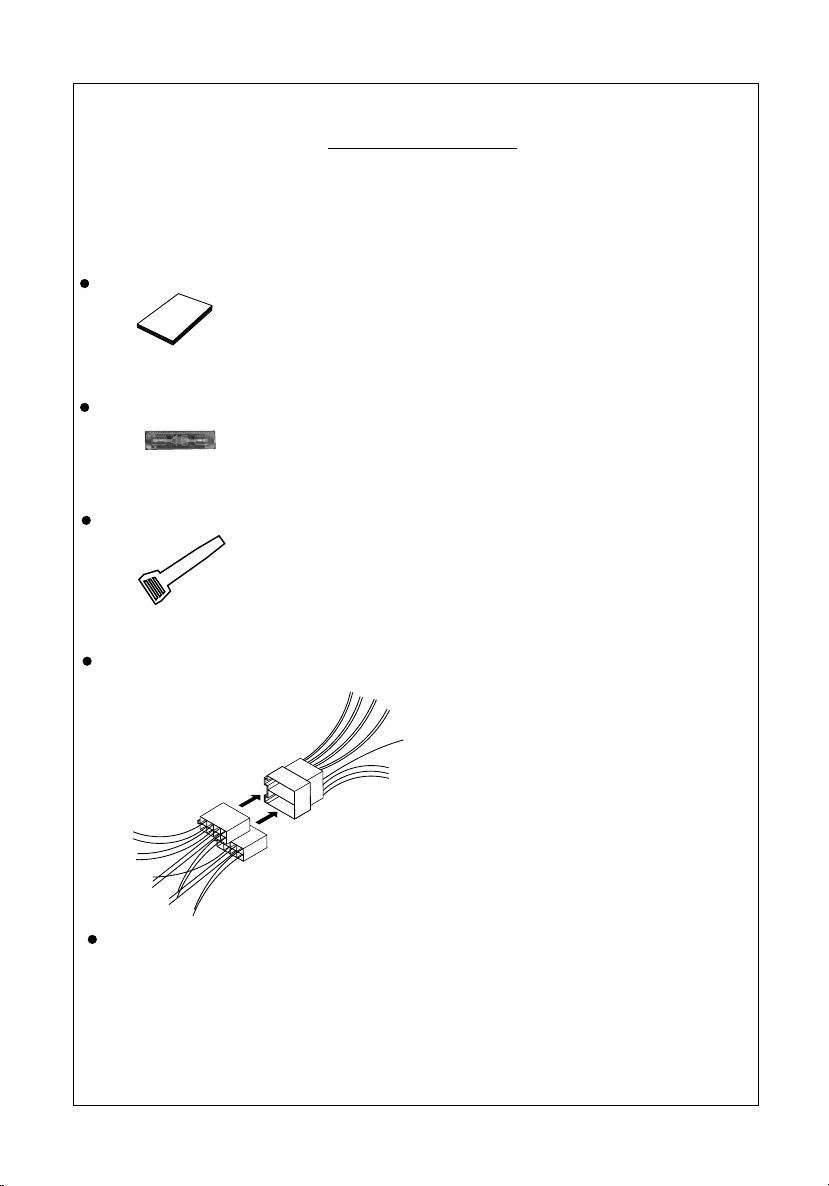
ACCESSORIES
When first unpacking your new in Car Radio CD Player, please check first that the package
contains all of the items below. If something is missing, contact the store where you purchased
the player.
Owner’s Manual
Own
m
e
r
an
’s
ua
l
Spare Fuse
2 x Release key
For use when ISO plugs are not used on your vehicle
Main Unit
ISO Socket
1 X 5mm nut
1 X spring washer
1 12mm self-tapping screw
1 X 5mm screw
1 X support strap
1 X plain washer
CDE VERSION
P. 3
Page 4
INSTALLATION
Before finally installing the unit, carry out a sound check. If high distortion or intermittent sound
is experienced, it is possible that the wiring to the car's electric is poor, or that the battery needs
recharging.
Use only the parts included with the unit to ensure a safe and secure installation.
Consult with your nearest dealer if installation requires the drilling of holes or other
modifications to the vehicle.
Choose a mounting location carefully so that the unit will not interfere with the normal driving
functions of the vehicle.
If installation angle exceeds 30° from horizontal, the unit might not give its optimum
performance.
Avoid installing the unit where it would be subject to high temperature, such as from direct
sunlight, or from hot air, from heater, or where it would be subject to dust dirt or excessive
vibration.
Be sure to remove the front panel before installing the unit.
DIN FRONT/REAR-MOUNT
This unit can be installed either from “Front” (conventional DIN Front-mount) or “Rear”(DIN
Rear-mount installation, utilizing threaded screw holes at the sides of the unit chassis). For details,
refer to the following illustrated installation methods A and B.
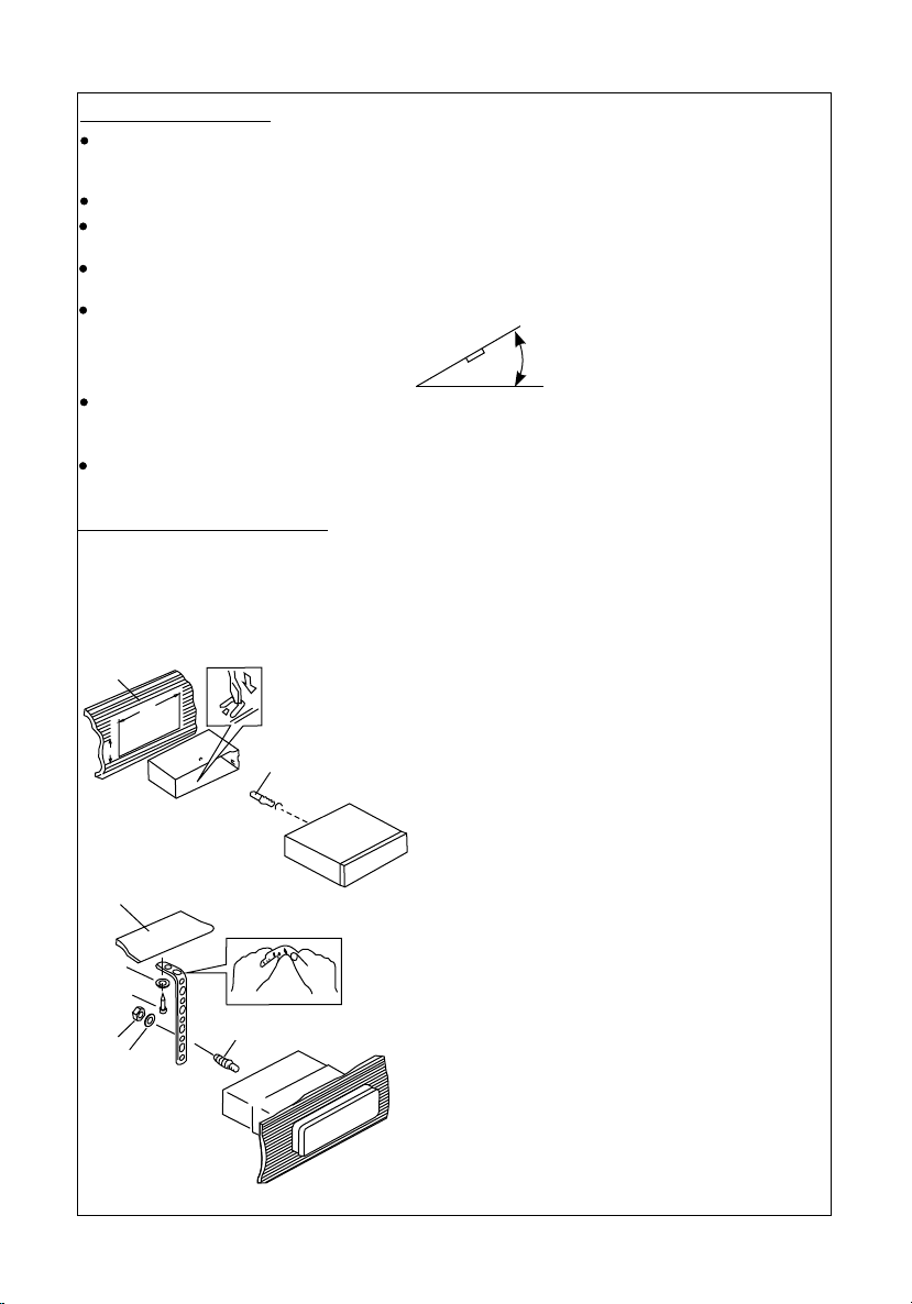
- DIN FRONT-MOUNT (Method A)
1
182
53
2
1. Dashboard
2. Mounting sleeve
3
3. Screw
30°
After inserting the half sleeve into the
dashboard, select the appropriate tab
according to the thickness of the
dashboard material and bend them
inwards to secure the sleeve in place.
1
7
4
2
3
6
5
1. Dashboard
2. Nut (5mm)
3. Spring washer
4. Screw (4x12mm)
5. Screw
6. Support Strap
Be sure to use the support strap to
secure the back of the unit in place. The
strap can be bent by hand to the desired
angle.
7. Plain washer
P. 4
Page 5
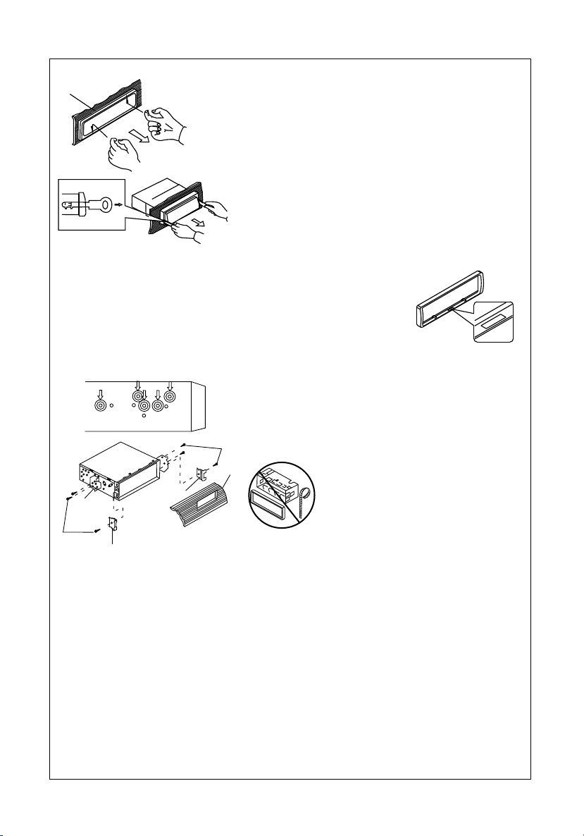
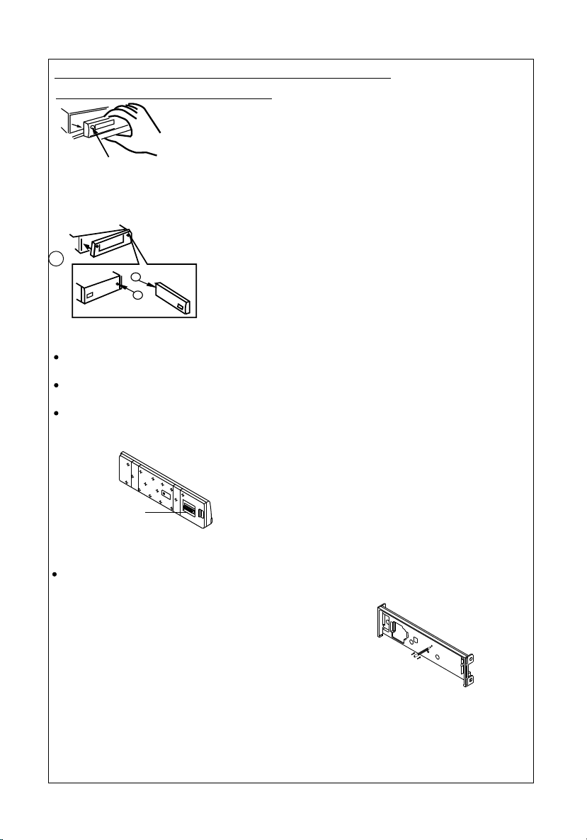
Removing the unit
a
a. Frame
b. Insert fingers into the groove in the
front of frame and pull out to remove
the frame. (When re-attaching the
frame, point the side with a groove
b
c
down wards and attach it.)
c. Insert the levers supplied with the
unit into the grooves at both sides of
the unit as shown in figure until they
click. Pulling the levers makes it
possible to remove the unit from the
dashboard.
- Trim Ring Installation:
Before attaching the trim ring, the side with a "Bottom" Label should be
seen on the lower edge of the ring (as shown on diagram).
Push the trim plate against the main panel until it clicks into place.
- DIN REAR-MOUNT (METHOD B)
Installation using the screw holes on the sides of the unit.
Fastening the unit to the factory radio mounting bracket.
1. Select a position where the screw
holes of the bracket and the screw
holes of the main unit become
aligned (are fitted) and tighten the
screws at 2 places on each side.
2
4
5
3
2. Screw
3. Factory radio mounting bracket.
4. Dashboard or Console
5. Hook (Remove this part)
Note: the mounting box, outer trim ring,
and half-sleeve are not used for method
2
B installation.
5
M
O
T
T
O
B
O
T M
T
O
B
P. 5
Page 6
USING THE DETACHABLE FRONT PANEL
Removing The Detachable Front Panel
1. Turn the power off
2. Press the front panel release button
PANEL RELEASE
BUTTON
Attaching the front panel
3. Remove the front panel
2
A
B
1. Insert the right side of the front panel into
the main unit. .
2. Press the left hand side of the front panel until
a "click" sound is heard
Precautions when handling the Detachable Front Panel
Always insert the front panel in the manner described above. Failure to do so may damage
both the panel and the main unit.
Do not drop the front panel. Always place it the the protective case provided when not in
use.
Do not touch the contacts on the front panel or the main unit. It may result in a poor
electrical connection.
Note:
If the front panel is dirty, wipe off the dirt with
soft, dry cloth only. To clean the contacts on
the front panel, use a cotton swab soaked in
Socket
isopropyl alcohol.
RESETTING THE UNIT:
After releasing the front panel, use a pencil or any non-metalic object to press & hold the
reset button for five seconds to reset the unit.
E
TRSE
P. 6
Page 7
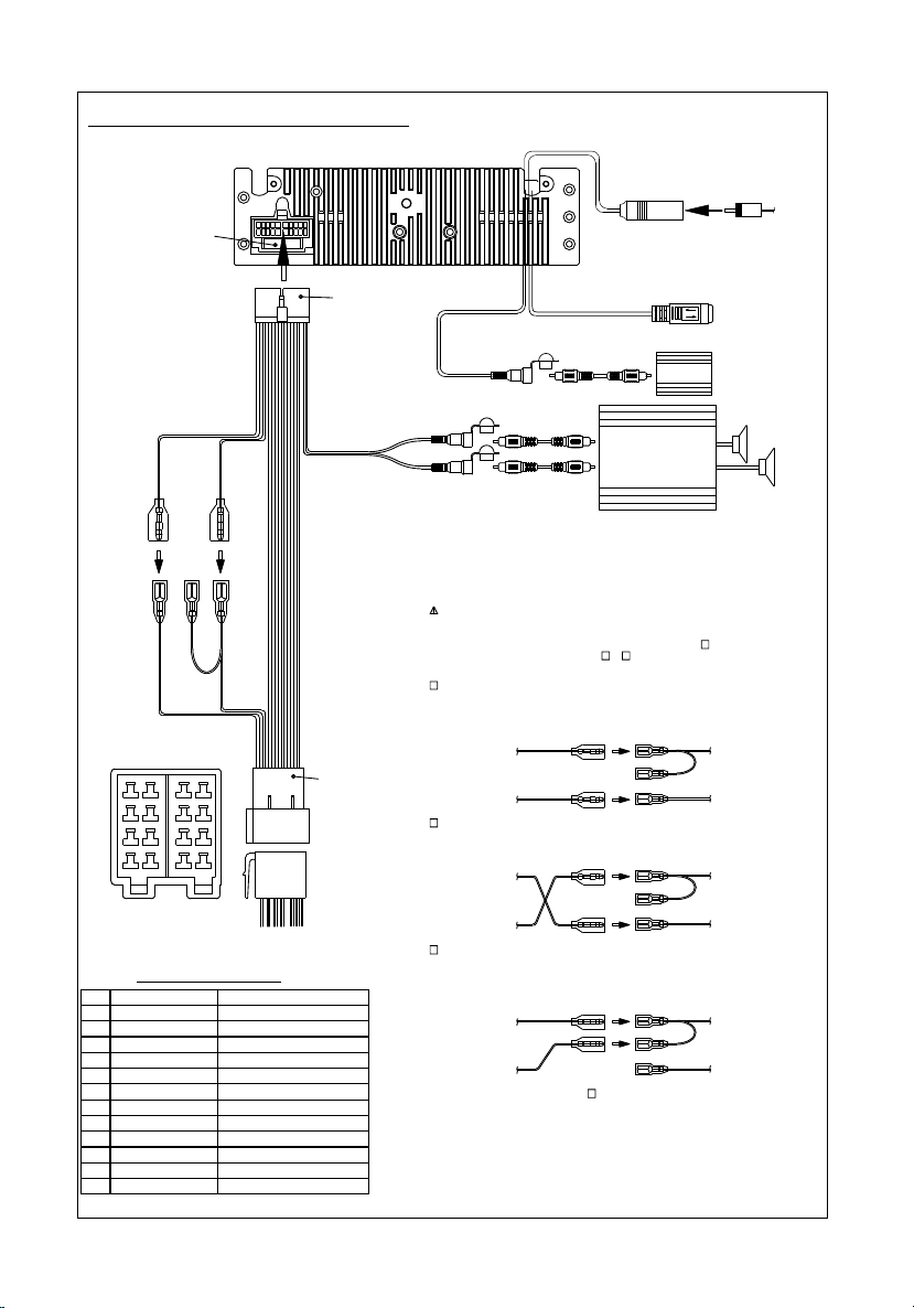
WIRING IDENTIFICATION
CONNECTOR B
8
7 8657
6
5
4
3
2
1
Figure 1
ISO CONNECTOR 4PIN+8PIN
FEMALE WITH MALE TERMINAL
ISO CONNECTOR WIRING CHART
WIRE COLOR
PIN
YELLOW
A4
A5
BLUE
RED
A7
BLACK
A8
VIOLET
B1
VIOLET/BLACK
B2
GREY
B3
GREY/BLACK
B4
WHITE
B5
WHITE/BLACK
B6
GREEN
B7
GREEN/BLACK
B8
FUSE
(YELLOW)
BATTERY WIRE
YELLOW
CONNECTOR A
43
21
FUNCTION/LABEL
BATTERY(+)
POWER ANTENNA
IGNITION(ACC)
GROUND
RIGHT REAR SPEAKER (+)
RIGHT REAR SPEAKER (-)
RIGHT FRONT SPEAKER (+)
RIGHT FRONT SPEAKER (-)
LEFT FRONT SPEAKER (+)
LEFT FRONT SPEAKER (-)
LEFT REAR SPEAKER (+)
LEFT REAR SPEAKER (-)
(RED)
IGNITION WIRE
RED
20-PIN
AUDIO/POWER
HARNESS
(See Figure 1)
GREY
REAR LINE OUT
ISO
CONNECTOR
(See Figure 1)
ANTENNA
SOCKET
BLUE
WHITE
iPod ready cable
WHITE
SUB WOOFER
WHITE
L-CH
RED
R-CH
WARNING Connecting the ISO Connector
The pin arrangement for the ISO connectors depends on the type of vehicle you
drive.Make sure to make the proper connections to prevent damage to the unit.
The default connection for the wiring harness is described in below. If the ISO
connector pins are set as described in or .make the connection as illustrated.
1
(Default setting) The A7 pin (red) of the vehicle's ISO connector is linked with
the ignition,and the A4 pin (yellow) is connected to the constant power supply.
Unit
Ignition wire
(RED)
Battery wire
(YELLOW)
2
The A7 pin (red) of the vehicle's ISO connector is connected to the constant power
supply, and the A4 pin (yellow) is linked to the ignition.
Unit
Ignition wire
(RED)
Battery wire
(YELLOW)
3
The A4 pin (yellow) of the vehicle's ISO connector is not connected to anything,
while the A7 pin (red) is connected to the constant power supply (or both the A7(red)
and A4 (yellow)pins are connected to the constant power supply).
Unit
Ignition wire
(RED)
Battery wire
(YELLOW)
When the connection is made as in above,the unit's power will not be linked to the
ignition key. For that reason,always make sure to turn off the unit's power when the
ignition is turned off.
To link the unit's power to the ignition,connect the ignition cable (ACC...red) to a
power source that can be turned on and off with the ignition key.
RCA-TO-RCA CABLES
RCA-TO-RCA CABLES
(not supplied)
(not supplied)
2
3
AMP
3
SUB
WOOFER
ANTENNA
CABLE
iPod
1
Vehicle
A7 PIN (RED)
A4 PIN(YELLOW)
Vehicle
A7 PIN (RED)
A4 PIN(YELLOW)
Vehicle
A7 PIN (RED)
A4 PIN(YELLOW)
P. 7
Page 8

PANEL OPEN/CLOSE OPERATION
OPEN / CLOSE THE PANEL:
Press the Open / Close button and the front panel will automatically slide down to allow access
to the CD slot. Press again to return the panel to the closed position.
LOADING A CD
When the panel is in the slide down position, the disc slot becomes accessible.
Insert a CD through the disc slot, the CD will be automatically loaded and the panel will also
close automatically & playback will begin.
If no CD is loaded, press the Open/Close button to return the panel to the closed position.
EJECTING A CD
Press Open / Close button to slide down the panel, if a CD is loaded, it will be ejected
automatically. No further key press is needed.
The CD can now be removed from the CD slot. If the CD is left in this position for more than
10 seconds, it will retract back into the CD mechanism and the front panel will return to the
closed position.
CAUTION:
A) Never try to manually slide up/down the fascia panel, as this will damage the mechanism.
Always use the Open/Close button.
B) Please do not try to detach / remove the front panel ( by pressing the detach button ) or
attach the front panel when the panel is in the slide down position. This may cause serious
& permanent damage to the unit & panel. Only attach or detach the front panel when the
panel is in the closed position.
P. 8
Page 9

IDENTIFICATION OF CONTROLS AND FUNCTIONS
18
4
1
3
5
8
2
20
6
OPERATIONS:
KEY
Brief
Press
Pow er
1
2
3
4
5
6
7
8
9
10
11
12
13
14
15
16
17
18
19
20
21
22
Pane l Open & Cl ose
SEL ECT
Mod e
Volume Up / Down
Mut e
Disp lay
SELSEL
ENTERENTER
LO/DXLO/ DX
22
SYSTE M
7
Press
& hold
Sub -W
2 ZON E
ix-Ba ss
Men u
DISPDI SP
MENUMENU
MUTEMUTE
AS/PSAS/PS
11
PAUPAU
12
11
Brief
Press
22
INTIN T
13
TUNER
33
RPTRPT
14
RDMRDM
44
55
66
15
16
CD/MP 3/W MA
Press
& hold
Brief
Press
Ejec t
17
SEARCHSEARCH
BANDBAND
19
AFA F
SUB-WSUB-W
TATA
2 ZONE2 ZONE
Press
& hold
MODEMOD E
PTYPTY
9
10
21
iPo d
Brief
Press
Press
& hold
Pan el Re lea se bu tto n
AF
TA
PTY
PS
Pres et 1
Pres et 2
Pres et 3
Pres et 4
Pres et 5
Pres et 6
Band
See k
Up
See k
Dow n
LO/ DX
AS
Sto re Memo ry 1
Sto re Memo ry 2
Sto re Memo ry 3
Sto re Memo ry 4
Sto re Memo ry 5
Sto re Memo ry 6
Tune
Up
Tune
Dow n
Ente r
ID3
Pau se/P lay
Intr o
Rep eat
Ran dom
Fol der
Dow n
Fol der
UP
Fil e/
Fol der
Sea rch
Trac k /File
Up
Trac k /File
Dow n
Fold er Int ro
Fol der Re peat
Fol der Ra ndom
Fas t
For ward
Fast
Backw ard
Ente r
iPo d
inform ation
Pau se/P lay
Rep eat
Shu ffle
iPod
Sear ch
Fil e Up
Fil e
Dow n
Alb um Repe at
Alb um Shuf fle
Fas t
For ward
Fast
Backw ard
P. 9
Page 10

BASIC OPERATIONS
3) PANEL RELEASE BUTTON (REL)
Press this button to remove the front panel.
1) POWER ON/OFF BUTTON ( )
Press POWER button or any other button on the front of the radio (except Open/Eject)
to turn the unit on. Press POWER button again to turn the unit off.
7) MUTE BUTTON (MUTE)
Press the mute button momentarily to mute the audio volume. "Mute" will flash in the
display. Press the mute button again to restore volume to the previous setting.
8) SUB-WOOFER (SUB-W)
Press & hold the SUB-W button to turn the Sub-woofer function On. “Sub-woofer” will
appear on the LCD display for 3 seconds. press the SUB-W button again to turn off the
Sub-woofer function.
The operation of this function is described fully on page 13.
The Subwoofer Level and Low Pass Filter control will only appear in the Audio Menu
if the Subwoofer function is currently activated 'On”.
10) iX-BASS BUTTON (iX-Bass )
Press & hold the iX-Bass button to turn on the IX-Bass function. “iX-Bass” will appear in the
LCD display for 3 seconds. Press the iX-Bass button again to turn off the IX-Bass function.
The operation of this function is described fully on page 13.
The IX-Bass Boost Level control will only appear in the Audio Menu if
function is currently activated 'On”.
5) MODE BUTTON (MODE)
Press MODE button to select a different mode of operation as indicated on the display
panel. Available modes include are: Tuner, CD, I-Pod.
6) VOLUME UP/ DOWN BUTTON
Use these buttons to adjust the volume up or down. When volume is adjusted, the volume
level will be shown on the display panel as a number ranging from 0 (lowest) to 46
(highest).
18) DISPLAY (DISP)
Briefly Press the DISPLAY/MENU button repeatedly to select the following different
Display options:
Spectrum mode 1 > Spectrum mode 2 > Spectrum mode 3 > Default Display.
the iX-Bass
Default Display
True S pec tru m Ana lyz er mo de 1
True S pec tru m Ana lyz er mo de 2
True S pec tru m Ana lyz er mo de 3
IGNITION OFF CLOCK RECALL
The user can recall the clock time by pressing the DISPLAY button, even when ignition is off.
P. 10
Page 11

MENU OPERATION
18) MENU FUNCTION LIST (MENU)
Press & hold DISPLAY/ MENU to access the menu. Will appear in the display
momentarily. Navigate the menu by pressing DISPLAY/ MENU button to move forward to the next
option. The menu can also be navigated by using the Tuning Up or Tuning Down Button to move
to the next or previous option. Once the desired option appears in the display, adjust that option
by presing the volume up / down button within 5 seconds. The following options are adjusted
through this menu feature.
Contrast
The contrast level of the display is set at "CONTRAST 05" by default. Press the volume up/down
button to adjust the contrast level from 00 to 10.
Dimmer
The dimmer feature of the display is set to "DIMMER High" by default. Press the volume up/down
button to turn the dimmer to the Iow setting.
Clock Format
This option allows selection of a 12 hour or 24 hour clock format. "CLK FORMAT 12H" is the
Default setting. Press the volume up/down button to change to the 24 hour clock format.
Time Set
The time on the clock will be set to 12:00 as the default. Program the current time by pressing the
volume up button to adjust the minutes and pressing the volume down button to adjust the hours.
Local / Distance Select
This feature is used to designate the strength of the signals at which the radio will stop during
automatic tuning. "Distance" is the default, allowing the radio to stop at a broader range of signals. To
set the unit to select only strong local stations during automatic tuning, Press the volume up/down
button until "Local" appears in the display.
AREA (TUNER FREQUENCY SPACING)
This option allows the selection of the frequency spacing appropriate for your area. It is set to
Europe area by default. We do not recommend that you change this setting, as the other
areas available in this feature use different frequency spacings. Therefore your unit may not
tune to radio stations correctly if another area is selected.
If you require any further advice on this feature, please contact our Customer helpline on 0871
230 1777.
Regional On/Off (Region)
This option will check whether an alternative frequency is a real alternative for the current
station. Region Off is displayed by default. This means that the the region identification
code in the PI code is ignored.
If Region On is selected (using the volume buttons) the PI codes must be identical.
For best performance, it is recommended that the region function is turned off.
The Regional function On/Off Setting can only be used when the “AF” function is “on”
Programmable Turn-on Volume (VOL PGM)
This option allows selection of the volume level the radio will automatically assume when
first turned on. "VOL PGM 12 " is the default setting. You can program the unit to turn on at
any desired volume level.
To program a specific volume level for the radio to turn on at, press the volume up/down
button to select the desired volume level. Within 5 seconds.
Beep Tone
The beep tone feature allows the selection of an audible beep tone to be heard each time
a button is pressed. "BEEP TONE On" is the default display. Press the volume up/down
button to select the "BEEP TONE Off" option.
P. 11
Page 12

DUAL ZONE OPERATION
This unit is equipped with the advance feature “Dual Zone”. This function is useful if the
user wants to select different modes of the audio output source for Front and Rear
Speakers. The details of this operation are as follows:
On/Off operation
“Off” is the default setting.
Press & hold the “2-Zone” button on the control panel to switch between
Dual Zone On or Off. The “2-Zone” icon will appear in the LCD when Dual Zone is selected
TO Select Front / Rear Sources
When 2-Zone ON is selected, briefly Press the “SEL” button repeatedly to change
between the F-Zone (Front ) and the R-Zone (Rear) sources.
When Front Zone “F-Zone” is selected, use the volume buttons to navigate through
differe
Tuner> CDP> iPod.
When Rear Zone “R-Zone” is selected, use the volume buttons to navigate through
different modes:
Tuner> CDP> iPod are available for selection for Rear Speakers Audio Output.
If no selection is made, the unit will return to the previous mode after 5 seconds
Function of Front / Rear Sources
The Front Panel control buttons are defaulted to control the FRONT source's function /
operation.
When DUAL ZONE is turned “ON”, the Mode button is used to change between the Front
Source & Rear Source. Press mode button repeatedly to toggle between Front and Rear
Mode.
When Rear source is selected by the Mode button, you can make changes to the volume.
The LCD will return to displaying the front source after a short time, if no further buttons are
pressed.
The Default Setting When Dual Zone “ON”
When DUAL ZONE is turned on, the audio output will be muted for about 1 second.
The default Volume level is “12” for both Front & Rear ZONE audio output. (or the Volume Level
set as VOL PGM
The LCD display is defaulted to display the Front Mode.
When Dual Zone is “ON”, it is not possible to change the Audio settings other than volume.
The Default Setting When Dual Zone “OFF”
When DUAL ZONE is turned OFF, the audio source will revert to whatever the front audio
source is currently set to.
. See page 11 for details on how to set programmable turn on volume.)
.
P. 12
Page 13

AUDIO OPERATION
Audio Menu
Briefly Press the “SEL” button to access the Audio Menu. Use the SEL button to toggle
between the various available menu options and the Volume buttons to change the values of
each setting.
The unit will automatically return to the previous mode 5 seconds after the last button is
pressed.
VOLUME (Volume Level)
Use the volume buttons to adjust the volume Up/Down. The LCD will show the current
volume level as a number between 00 (lowest) and 46 (highest).
SUBWOOFER (Sub-woofer Level)
The Subwoofer level can be adjusted from 00 to 12.
The Subwoofer level control is only effective when the unit is connected to an optional
subwoofer.
The Sub-woofer level control option will only appear in the Audio Menu if the “Sub-woofer”
function is activated by pressing and holding the “Sub-w” button on the control panel.
SUB-W LPF (Sub-woofer Low Pass Filter)
The Subwoofer Low Pass Filter can be adjusted to 80, 120 or 160 Hz.
iX-BASS (iX-Bass Level)
The iX Bass boost can be adjusted to Low, Mid or High setting.
The iX-Bass option will only appear in the Audio Menu if the function is activated by
pressing and holding the “iX-Bass” button on the control panel.
BASS (Bass Level)
The Bass level can be adjusted from -6 to +6.
BASS -CFQ (Bass Center Frequency).
The Bass CFQ (Center Frequency can be adjusted between 60, 80, 100 and 200Hz.
BASS-Q: (Bass Quality Factor)
The Bass-Q (Bass Quality Factor) can be adjusted as shown in Fig 1.
Figure 1 shows the Bass Quality factor (Curve characteristics) of each step.
15.0
12.5
10.0
7.5
1W
2W
5.0
Level
(dB)
2.5
0.0
10.0 100.0 1.0K 10.0K
MIDDLE (Middle Level)
The mid-range setting can be adjusted from -6 to +6.
MID-CFQ (Middle Center Frequency)
The MID-CFQ (Middle Centre Frequency) can be adjusted between 500Hz, 1KHz, 1.5KHz
and 2.5KHz.
1N
2N
Figure 1
Frequency (Hz)
P. 13
Page 14

MIDDLE-Q (Middle Quality Factor)
The Middle-Q (Middle Quality Factor) can be adjusted as shown in Fig 2.
Figure 2 shows the middle Quality factor (Curve characteristics) of each step.
15
10
Level
(dB)
TREBLE (Treble Level)
1.10
1N
2N
3
5
0
10
100
Frequency (Hz)
1.10
1W
2W
4
1.10
5
Figure 2
The Treble level can be adjusted from -6 to +6.
TRE-CFQ (Treble Center Frequency)
The TRE-CFQ (Treble Centre Frequency) can be adjusted between 10KHz, 12.5KHz,
15KHz and 17.5KHz.
BALANCE
The Balance can be adjusted between the right and left channels. R12 is the maximum
bias to the right hand speakers and L12 is the maximum bias to the left hand speakers.
C00 means that the balance is centralized.
FADER
The Fader control allows the sound level to be adjusted between the front and rear
speakers.
The display will show R12 when the sound level is fully adjusted to the rear speakers and
F12 when fully adjusted to the front speakers.
C00 means that the sound level is equally divided between both front and rear speakers.
P. 14
Page 15

TUNER OPERATION
19) BAND BUTTON (BAND/SEARCH)
Press BAND to change between FM band and MW band.
20-21) TUNING UP/DOWN BUTTON ( )
Manual Tuning
Press and hold the tuning buttons to enter manual tuning mode. This allows fine tuning of
the radio, one frequency spacing at a time.
The unit will automatically return to auto tuning mode after a few seconds.
Auto Seek Tuning
Press the Up Tuning or Down Tuning button briefly to move to next station automatically.
12-17) PRESET STATIONS BUTTONS
The six numbered preset buttons store and recall stations for each band.
Store a Station
Select a band (if needed), then tune to a desired station. Press and hold the preset button
that you wish to store the station under. The preset number will appear in the display.
Recall a Station
Select a band (if needed). Press a preset button to select the corresponding stored station.
11) AUTOMATICALLY STORE / PRESET SCAN (AS/PS)
Automatically Store
Press and hold the AS/PS button. The unit will scan and store the first 6 strongest radio
stations in the preset memory. There are 6 preset memory positions for each band.
Preset Scan
Scan stations stored in the current band. Select a band (if needed). Press AS/PS button
briefly. The unit will pause for ten seconds at each preset station. Press AS/PS button again
to stop scanning when the desired station is reached.
STEREO
The unit will automatically pick up a stereo signal, when available. When in stereo mode,
the ST icon appears in the display. When no stereo signal is available, the unit will
automatically revert to mono operation, and no icon will be displayed.
22) LOCAL / DISTANCE SELECTOR
Briefly press LO/DX button to select between Local or Distant mode. This feature is used to
designate the strength of the signals at which the radio will stop during automatic tuning.
"Distance" is the default, allowing the radio to stop at a broader range of signals. To set the
unit to select only strong local stations during automatic tuning,press this button until the
"LOC" icon appears in the display.
P. 15
Page 16

RDS OPERATION
RDS functions
The unit is equipped with the following RDS function:
- AF Alternative Frequencies
- CT Clock Time
- EON Enchanced other Network
- PI Program identifications
- PS Program service name
- PTY Program Type
- REG Regional Change
- TA Traffic Announcement
- TP Traffic program
1. AF Function
Briefly press the AF button to toggle between AF ON and AF OFF mode. When AF mode is
ON, and the current radio station reception is becomming weak
switch to a different frequency on the same network with stronger signal.
Note: Factory Default setting is “AF ON”
2. TA Function
Briefly press the TA button to activate Traffic Announcement mode. TA ON will show in the
display.
When TA mode is selected, the unit will automatically switch to a station broadcasting a
traffic announcement, regardless of the current mode. When a traffic announcement starts,
“TRAFFIC INFO” will show on the LCD, The traffic announcement can be cancelled by
pressing the TA button at any stage.
In TA mode, if the TP signal is lost for more than 60 seconds, an audible "beep" will be heard
and the display will show "Lost TP,TA. The unit will then search for another station with TA.
When the TP icon is not lit up for 60 seconds, TA beep Alarm tone is heard and the LCD will
show “Lost TP, TA”. TA seek will activate and search for another TA station.
3. PTY Function
Briefly press the PTY button to enter PTY select mode. The PTY icon will show in the display.
Use the Volume Up/Down buttons to select the desired programme type.
Once the desired programme type is found, press either SEL or Tun Up/Down to search for
a station of that particular type. PTY SEEK will be shown in the display.
If no station can be found of the type selected, the display will show No match PTY and
return to the previous mode.
6 favourite PTY stations can be stored in memory positions 1-6.
After selecting a PTY station to store, press and hold the desired preset button.
To recall a stored PTY station, enter PTY mode, then briefly press the preset button
corresponding to the stored stations.
Music Group
POP , ROCK
EASY, LIGHT
CLASSICS, OTHER
JAZZ, COUNTRY
NATION, OLDIES
FOLK
Note: PTY preset memory
is defaulted to the following until changed by the user.
Speech Group
NEWS, AFFAIRS, INFO
SPORT, EDUCATE, DRAMA
CULTURE, SCIENCE, VARIED
WEATHER,FINANCE, CHILDREN
SOCIAL, RELIGION, PHONE IN
TRAVEL, LEISURE, DOCUMENT
M1/News, M2/Information, M3/Pop Music, M4/Sports, M5/Classics, M6/Finance.
, the unit will automatically
P. 16
Page 17

CD /MP3/WMA OPERATION
INSERT AND EJECT CD
Open the motorised front panel as described on page 6 of this instruction book.Insert a CD
into the CD clot and the disc will begin to play. Press the Eject button to stop CD play and
eject the CD. The unit does not have to be turned on to eject the CD.
CD-DA OPERATION
12) PAUSE BUTTON
Press the pause button to pause disc play. Press the pause button again to resume disc
Play.
20-21) TRACK SELECT
Press the Up Tuning or Down Tuning button ( ) briefly to advance to the next track
on the CD, The selected track number will appear on the display. Press and hold the Up
Tuning or Down Tuning button ( ) for more than one second to fast
forward or fast reverse through the disc. CD playback will resume when the button is
released.
14) REPEAT BUTTON (RPT)
Press REPEAT BUTTON (RPT) during disc play to continuously repeat the track. Press
REPEAT BUTTON (RPT) to return to normal disc playback.
15) RANDOM BUTTON (RDM)
Press RANDOM BUTTON (RDM) during disc play to play all tracks on a CD in a random
order. Press RANDOM BUTTON (RDM) to resume normal playback.
13) INTRO SCAN BUTTON (INT)
During disc play, press INTRO SCAN BUTTON (INT) to play the first 10 seconds of each
track on the disc. When the desired track is reached, press INTRO SCAN BUTTON (INT)
again to end the scan and play the selected track.
MP3/WMA OPERATION
This unit can play MP3/WMA directly from files contained on a CD-R/RW.
Notes on Disc Play
Depending on the media type and recording method, some CD-R/RW's may be incompatible
with this unit.
using CD-RW, use full format rather than quick format to prevent malfunction.
Notes on MP3/WMA Play
This unit can play MP3 (MPEG1, 2, 2.5 Audio Layer 3). However, the MP3 recording media and
accepted formats are limited. When writing MP3/WMA, pay attention to the following restrictions.
Acceptable Media Formats
The following formats are acceptable for the media used in this unit. The maximum number of
characters used for file name including the delimiter (".") and three-character extension are
indicated in (brackets).
ISO 9660 Level 1 (11 characters)
ISO 9660 Level 2 (31 characters)
Joliet (31 characters)
Romeo (31 characters)
The disc types supported by this unit are CD-ROM, CD-R and CD-RW. When
P. 17
Page 18

Up to 200 characters can be displayed in the long file name format. For a list of available
characters, see the instruction manual of the writing software and the section “Entering File and
Folder Names” below. The media reproducible on this unit has the following limitations:
Maximum number of nested folders: 8
Maximum number of files per disc: 999
Maximum number of files per media device: 2000
Maximum number of folders per disc: 255
MP3/WMA written in formats other than the above may not be successfully played and their file
names or folder names may not be properly displayed.
MP3/WMA Encoder and CD Writer Settings
Use the following settings when compressing audio data in MP3 data with the MP3 encoder.
Transfer bit rate : 32- 320 kbps
Sampling frequency : 32,44.1,48 kHz(WMA) 16,22.05,24,32,44.1, 48kHz (MP3)
When using a CD writer to record MP3/WMA up to the maximum disc capacity, disable
additional writing.
ID3 Tag
This unit supports ID3 tag versions 1.0 and 1.1.
The unit also supports CD-TEXT encoded discs for Album, Track and Artist Title information.
File and Folder Names
Names using the code list characters are the only file names and folder names that can be
entered and displayed. Using any other character will cause the file and folder names to be
displayed incorrectly. The unit recognizes and plays only files with the MP3/WMA extension.
A file name entered with characters not on the code list may not play correctly.
When a disc containing MP3/WMA files is loaded, the unit checks all data. If the disc contains
many folders or non-MP3/WMA files, Play back will be delayed, it may take time for the unit to
move to the next file, and searches may not be performed smoothly. Loading such a disc may
produce loud noise and cause damage to the speakers. Do not attempt to play a disc
containing a non-MP3/WMA file with the MP3/WMA extension or a disc containing non
MP3/WMA files.
Bit Rates
The unit supports bit rates from 32 - 320 kbps.
P. 18
Page 19

Files Playing Order
When playing MP3/WMA files, searching for folders, files etc., the order in which they play is
determined by the order in which they were written to disc by the PC.
An outline of a disc containing MP3/WMA files is shown below. Subfolders are shown within
the the current folder.
1 LEVEL 2 LEVEL 3 LEVEL 4 LEVEL
ROOT
01
001.MP3
002.MP3
003.MP3
004.MP3
04
05
06
07
“NOT DISPLAYED”
X
009.MP3
010.MP3
011.MP3
012.WMA
013.WMA
014.WMA
015.MP3
016.MP3
017.MP3
018.MP3
“NOT DISPLAYED”
08
019.MP3
020.MP3
The equipment assigns folder
numbers. The user can not assign
folder numbers.
X
09
021.WMA
022.WMA
023.WMA
It is not possible to check folders that
do not include MP3/WMA files.
(These folders will be skipped without
displaying the folder number and
name)
“NOT DISPLAYED”
X
02
03
“NOT DISPLAYED”
005.MP3
006.MP3
007.MP3
008.MP3
X
FILE/FOLDER PLAY
There are three different play methods as following:
File/Folder Intro play:
Press and hold INT button to hear the first 10 seconds of all of the files in the current folder.
To resume normal playback, press and hold the INT button.
Briefly press the INT button to hear the first 10 seconds of all files on the currently loaded
disc.
To resume normal playback, briefly press INT button.
P. 19
Page 20

File/Folder Repeat play :
Press and hold the RPT button to repeat all files in the current folder.
To resume normal playback, press and hold the RPT button.
Briefly press the RPT button to repeat the currently playing file.
To resume normal playback, briefly press the RPT button.
File/Folder Random play:
Press and hold the RDM button to hear a random selection of files from the current folder.
To resume normal playback, press and hold the RDM button.
Briefly press the RDM button to hear a random selection of files from the entire disc
currently being played.
To resume normal playback, briefly press the RDM button.
Folder Up / Down Play
Briefly press Folder Down button to access the previous folder.
Briefly press Folder Up button to advance to the next folder.
MP3/WMA File or Folder Search
Folder / Files Navigate Searching
Press the BAND button. The LCD will display "Navigate". Use the Volume Up/Down buttons to
navigate through all the folders & sub-folders on the disc. The folder names will be displayed
on the LCD.
Briefly press the SEL button to select a folder, then press SEL again to begin playback of the
first track in that folder.
Alternatively, press and hold the SEL button on any given folder to begin direct playback.
During navigation search, press the AS/PS button to move back to the last upper level of a
folder.
ID3 INFORMATION DISPLAY
If a disc containing files with ID3 tagging is being played, information such as album title, artist
etc. can be displayed in the LCD and will scroll during playback. Press AS/PS to manually view
the different ID3 tag information.
The following icons are used in the LCD display to show the current ID3
information being viewed:
ICON DESCRIPTION
FOLDER ICON
FILE ICON
TRACK ICON
ARTIST ICON
ALBUM ICON
P. 20
Page 21

IPod OPERATION
This unit allows for I-pod devices to be connected and controlled by the buttons on the front panel.
The I-pod track information can also be viewed on the LCD of this unit.
iPod Compatibility Chart
This unit supports the following I-pod devices:
iPod 1G Not Supported
iPod 2G Not Supported
iPod 3G Firmware Version 2.2
iPod Mini All versions
iPod 4G All versions
iPod Photo All versions
iPod Nano All versions
iPod 5G(Video) All versions
Connecting an iPod to this unit
8 Din iPod Ready Cable
HEAD UNIT
iPod
iPod iPod
photo
NOTE
This unit is NOT ABLE to play video files. Any video files contained in a connected I-pod would be
ignored by this unit.
Turning iPod Power On and Off
IMPORTANT NOTE
Remember to disconnect the I-pod from this unit when not in use. Never leave your I-pod
inside the vehicle when unattended.The iPod power turns on automatically as soon as it is
connected to the 30 Pin Connector and as long as the vehicle's ignition is turned ON. The iPod
power can be turned OFF by removing the iPod from the 30 Pin Connector or if the vehicle's ignition
is turned OFF. Under this condition the iPod will go into pause mode
mode about 2 minutes later.
While the iPod is connected, the power cannot be turned on or off from the iPod itself.
Tips
“ ” to disconnect will be shown in the iPod's display while it is connected to the unit .
OK to disconnect
iPod Battery Charging
While connected to the unit, the iPod will automatically start re-charging as long as the vehicle's
ignition key is turn to ACC or ON.
Switch to iPod Mode
When the Head unit is powered on and the iPod is connected to the 30 pin connector,
press the mode button to change to iPod mode. The unit will display for a
while followed by .
automatically. Use the Mode button to stop playback from the I-pod and switch to CD or Tuner mode.
iPod
mini
nano
iPod Cable
initially and then into sleep
When the files from the I-pod have been read, playback will begin
P. 21
Page 22

iPod information Display
This unit can display the Song, Artist, Album name and Elapsed time on the LCD display. This
information can be manually displayed by pressing the AS/PS button during music file playback.
I-pod search mode
During iPod playback mode, press the BAND button to enter the iPod Searching Mode. Pressing
BAND button repeatedly
1) Playlist
2) Artist
3) Album
4) Song
5) Genre
Press the SEL/ button to select the search category, then use the volume buttons to navigate
through the album, artist, song etc.
Press the SEL button to select the desired album or song. The display will show "Searching"
whilst the unit is accessing the desired song.
Press AS/PS to cancel the current search.
Song Select
Briefly press the Track UP (>>) or Track DOWN (<<) buttons to skip to the next or previous
song. Press and Hold Track UP (>>) or Track DOWN (<<) buttons to fast forward or fast
reverse through the current track. Release the buttons to resume normal playback.
Song Repeat / Repeat All play :
Press and hold the RPT button during I-pod playback to repeat all songs in the current album.
To resume normal playback from the I-pod, press and hold RPT button.
Briefly press the RPT button to repeat the song currently playing. The song will continue to be
repeated until the function is cancelled by pressing the RPT button again.
will allow the following categories to be searched for:
Shuffle Function
Press and hold the RDM button during I-pod playback to activate Shuffle Album function. This
allows random playback of albums contained in the I-pod.
To resume normal playback, press and hold the RDM button.
Press the RDM button briefly to activate the Shuffle Play function. This allows random playback of
all songs contained in the I-pod. To resume normal playback, press the RDM button again.
P. 22
Page 23

NOTE ON DISCS
MOISTURE CONDENSATION
In damp or humid conditions, moisture may condense on the lense inside the unit. Should this
occur, the unit will not operate properly. To restore correct operation, please remove the CD and
allow 1 hour for any moisture to evaporate.
NOTES ON CDs
1.
A dirty or defective disc may cause sound
dropouts while playing. To enjoy optimum
sound, handle the disc as follows.
Handle the disc by its edge. To keep the disc
clean, do not touch the surface (P.1).
NOTES ON DISCS
If you use the discs such as those shown
below, the sticky residue can cause the CD
to stop spi nni ng a nd m ay c aus e
malfunction or ruin your discs.
Do not use second-hand or rental CDs that
have a sticky residue on the surface (for
example, from peeled-off stickers or from
ink, or glue leaking from under the stickers).
P. 1
Do not stick paper or tape on the disc (P.2).
2.
P. 2
Do not expose the discs to direct sunlight or
3.
heat sources such as hot air-ducts, or leave
them in a car parked in direct sunlight where
there can be a considerabl e ri se in
temperature inside the car (P.3).
P. 3
4.
Before playing, clean the discs with an
optional cleaning cloth. Wipe each disc from
the centre out (P.4).
P. 4
Do not use solvents such as benzine,
5.
thinners, commercially available cleaners, or
antistatic spray intended for analog discs.
CDE VERSION
P. 23
****
*******
*******
*******
P. 5
*******
Do not use rental CDs with old labels that
are beginning to peel off.
Stickers that are beginning
to peel away, leaving a
sticky residue (P.6).
P. 6
**************
*******
*******
*******
Do not use your CDs with labels or stickers
attached.
Labels are attached (P.7).
Do Not Use Special Shape CDs
P. 7
*******
*******
*******
*******
*******
Use of special shape CDs may cause the
unit to malfunction.(P.8).
P. 8
Be sure to use CDs with these markings
RECORDABLE
REWRITABLE
TEXT
Only for this unit.
CD-Rs and CD-RWs which have not
undergone finalization process cannot be
played. (For more information on
finalization processing, refer to the manual
for your CD-R/CD-RW writing software or
CD-R/CD-RW recorder.) Additionally,
depending on the recording status, it may
prove impossible to play certain CDs
recorded on CD-R or CD-RW.
Page 24

SPECIFICATIONS
CD PLAYER
System
Usable disc
Sampling frequency
No of quantization bits
Frequency
Number of channels
S/N Ratio
RADIO SECTION
FM
Frequency Range
Intermediate Frequency
Usable Sensitivity
Stereo Separation
S/N Ratio
MW
Frequency Range
Intermediate Frequency
Usable Sensitivity
S/N Ratio
GENERAL
Power Supply
Speaker impedance
Power Output
Chassis Dimensions (in mm)
Weight
Compact disc audio system
Compact disc
44.1KHz
1bit
5-20,000Hz
2 stereo
70dB
87.5-108 Mhz
10.7 MHz
Better than 15dB at S/N 30 dB
25 dB at 1KHz
50 dB
522-1620 Khz
450KHz
Better than 45dB
40 dB
DC 11 -14V, Negative Ground
4 ohms
4 x 40W
178W X 175D X 50H
1.8Kg
NOTE:
Specifications are subject to change without prior notice.
P. 24
Page 25

TROUBLE SHOOTING
Before going through the check list, first refer to the back to the connection and operating procedures.
Most problems that you may encounter with your unit are covered in the list below. Should any problems
persist after you have checked this list, please contact our Customer Helpline on 0871 230 1777 for further
assistance.
Symptom
No power
The car ignition is not on.
Cause
Solution
If the power supply is properly connected
to the car accessory terminal, switch the
ignition key to “ACC”
Disc cannot be loaded
or ejected
No sound
The operation keys do
not work
Sound skips.
The radio does not
work.
The radio station
automatic selection
does not work.
ERROR 1
ERROR 2
If at any time in the future you should need to dispose of this product please note
that Waste electrical products should not be disposed of with household waste.
Please recycle where facilities exist. Check with your Local Authority or retailer
for recycling advice.(Waste Electrical and Electronic Equipment Directive)
The fuse is blown.
Presence of CD disc inside
the player.
Inserting the disc in reverse
direction.
Compact disc is extremely
dirty or defective disc.
Temperature inside the car is
too high.
Condensation.
Volume is set to minimum.
Wiring is not properly
connected.
The built-in microcomputer is
operating incorrectly.
The installation angle is
more than 30 degrees.
The disc is extremely dirty or
defective.
The antenna cable is not
connected.
The signals are too weak.
Mechanism Error
Servo Error
P. 25
Replace the fuse.
Remove the disc in the player, then try
again.
Insert the compact disc with the label
facing upward.
Clean the disc or try to play a new one.
Cool off or until the ambient temperature
returns to normal.
Leave the player to off for an hour or so,
then try again.
Adjust volume to a desired level.
Check wiring connection.
Press the RESET button.
Front panel is not making good contact with
the connections pins on the main unit.
Adjust the installation angle to less 30
degrees.
Clean the compact disc, or try to play a
new one.
Insert the antenna cable firmly.
Select a station manually.
Press the reset button If the error is still
evident after pressing the reset button,
consult our Customer helpline.
Press the reset button If the error is still
evident after pressing the reset button,
consult our Customer helpline.
Page 26

cecustome rservice@albaplc.co.uk
helpline nu mber: 0871 230 1777
P. 26
 Loading...